
A Review on CubeSat Missions for Ionospheric Science

INESC TEC—Institute for Systems and Computer Engineering, Technology and Science, 4200-465 Porto, Portugal
*
Author to whom correspondence should be addressed.
†
These authors contributed equally to this work.
Aerospace 2023, 10(7), 622; https://doi.org/10.3390/aerospace10070622
Submission received: 23 May 2023
/
Revised: 23 June 2023
/
Accepted: 6 July 2023
/
Published: 8 July 2023
(This article belongs to the Section Astronautics & Space Science)
Abstract
:The ionosphere is a fundamental component of the Earth’s atmosphere, impacting human activities such as communication transmissions, navigation systems, satellite functions, power network systems, and natural gas pipelines, even endangering human life or health. As technology moves forward, understanding the impact of the ionosphere on our daily lives becomes increasingly important. CubeSats are a promising way to increase understanding of this important atmospheric layer. This paper reviews the state of the art of CubeSat missions designed for ionospheric studies. Their main instrumentation payload and orbits are also analyzed from the point of view of their importance for the missions. It also focuses on the importance of data and metadata, and makes an approach to the aspects that need to be improved.
1. Introduction
The ionosphere, hypothesized by Carl Friedrich Gauss in 1839, is the ionized part of Earth’s upper atmosphere, i.e., a layer of electrons and ionized atoms and molecules. The ionosphere base is at 70–80 km, extending upwards to space, overlapping with the thermosphere and the upper mesosphere [1]. Ionization is in general due to the interaction of solar radiation of short wavelength (extreme ultraviolet and X-ray radiation) with atmospheric constituents, but at high magnetic latitudes, high-energy particles become dominant sources of ionization.
Auroras are created by energetic particles traveling down the magnetic field lines at the Earth’s poles into the atmosphere and interacting with atmospheric gases [2]. The ionosphere is of the utmost importance for the study of Sun–Earth interactions and it is what allows us to have radio communications. This region is divided into different regions/layers depending on their features. From the lowest to the highest, we have regions D, E, F1, and F2. The first one, the D region, does not have the Sun’s ionizing radiation at night, and the oxygen and nitrogen molecules combine to become neutral. On the contrary, the E region stays charged at night, which allows us to have worldwide radio communications. Last is the F region with the greatest concentration of ions, where layer F1 only appears during daylight, and layer F2 is always present and above F1 [3]. The high-latitude ionosphere is the most non-stationary and inhomogeneous region, with diverse localized structures including phenomena such as poleward-moving auroral forms, polar cap patches, poleward boundary intensifications or auroral arcs, and knowledge on these structures and their variability is critical for the improvement of numerical ionospheric models [4].
The ionospheric variability has two main origins: the solar wind [5] and the variations in the troposphere and stratosphere [6,7]. The variation of the conditions in the space environment resulting from the interaction of the solar activity with Earth’s magnetosphere, ionosphere, and thermosphere, is called space weather [8]. Space weather events can be classified according to their strength and impact on infrastructure [9,10,11].
All the variations (both temporal and spatial) in the ionosphere can disturb different areas of daily life such as communication transmissions [12], navigation systems [13,14], satellite functions [15], power network systems [16,17], natural gas pipelines [18], and even endanger human life or health [19,20]. Therefore, as the impact of space weather events increases in our daily life due to our greater dependence on electrical/electronic and space-based technologies, so does the interest in its study [10,11].
A key way to understand these ionospheric variations and their effects, and even to create a system to prevent the damages associated with them, is to have direct information on the ionosphere. In situ measurements of the ionosphere and long-term observations across different locations allow us to understand the temporal evolution and the spatial structure of the ionosphere and the dominant physical processes involved. Some of the most important in situ measures are plasma density, electron temperature, ion density and temperature, and also atmospheric composition.
This paper is divided into six sections. Section 2 guide us throughout the history of the CubeSats. Section 3 makes an overview of some of the CubeSat missions designed for ionospheric studies, with their main features, scientific goals, payload, and orbit parameters. A summary of the main features of the general instrumentation on the payload is described in Section 4, followed by the characteristics of the most used orbits for this type of mission in Section 5. Section 6 presents an overview on the importance of the data and metadata from the missions. Section 7 addresses ionospheric models.
2. The CubeSat Paradigm
A Cube Satellite (CubeSat) is a downsized type of satellite. A 1U CubeSat is a 10 cm cube, and several of these blocks can be added to create 2U, 3U, 6U, and so on [21]. The concept was developed as student projects at the California Polytechnic State University and Stanford University. Right now they are used not only for educational purposes, but also for scientific, technological, and commercial roles. Several hundreds of them have already been launched so far [22].
As CubeSats are mainly student projects, and according to [23], about of the missions ended up failing. However, when missions are planned and carried out by teams with some background and experience, this rate is considerably lower. The main reason for failure has been a not well performed (or not performed at all) functional testing on the ground at a system integration level.
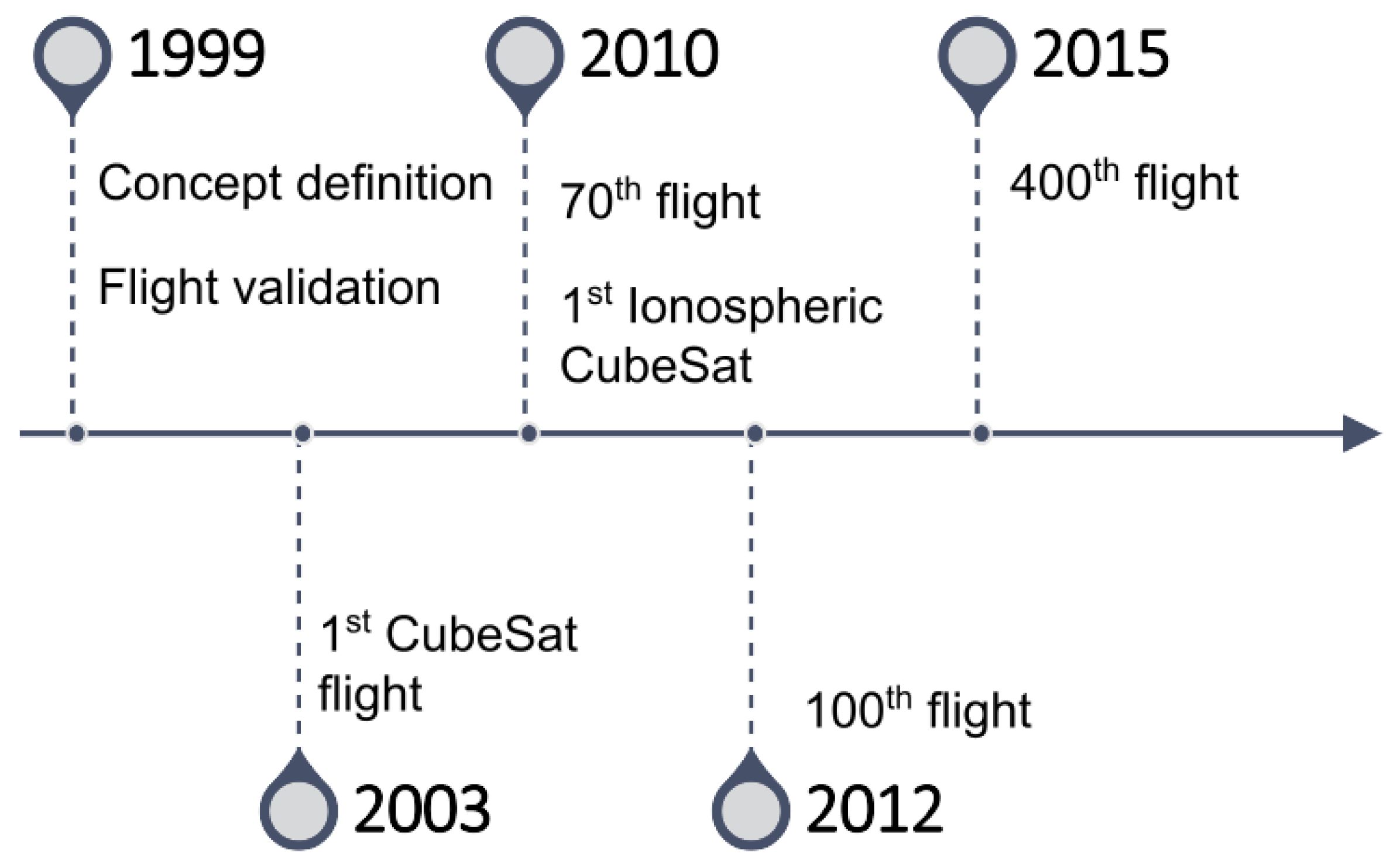
Throughout the history of Cubesats (Figure 1), and according the analysis made by [24], between 2000 and 2015, the majority of CubeSats launched were either from the USA or Europe, and have a form factor of 3U. It was also found that only of the missions launched in that period and reached orbit were successful.
Typically, small satellite missions are categorized by their main goal. For example, if the goal is to measure the plasma processes in the magnetosphere-ionosphere system, the mission goes into the “Solar and Space Physics (Heliophysics)” category, on the other hand, if it aims to carry out in situ investigations of planetary surfaces or atmospheres, it falls in the “Planetary Science” scope [25].
There are some reviews on this type of mission, for example, [26] reviews 39 small satellite missions grouped into five mission types: Astronomy and Astrophysics, Earth Science, Heliophysics, Planetary Science, and Technology demonstrations. Another example is [27], which makes a review on 130 CubeSat missions, grouped depending on their main goal: Astrophysics, Deep Space Exploration, Earth Science, Heliophysics: Space Weather, Spaceborne In Situ Laboratory, and Technology Demonstration. Some examples are missions to perform asteroid mining and a Lunar CubeSat Injector to identify locations of water sources on the Moon with the help of a spectrometer [28], and missions to quantify dust particles in orbit [29].
It is also well-established that space travel can cause a lot of damage to the astronauts’ health and with that came the necessity to better study the space environment to understand those risks and how to mitigate them. As CubeSat missions are developing, they become apt for biomedical studies, replacing the typical biomedical platforms used so far. The advantages of the use of CubeSat missions for these studies are described in [30].
A review of Thermospheric/Exospheric missions and Magnetospheric Missions is given by [31]. For the first ones, it provides the remote sensing method, the mission altitude range, and the in situ method for cold neutrals. For the magnetospheric missions, the key regions studied, the mission orbit, and the ion mass are presented.
The development of miniaturized components made of lighter and stronger materials that can last in space and also the improvement in the efficiency of power generation and power storage systems has contributed to the upgrade of sensor/satellite systems [32,33]. This development means that they ended up taking fewer resources, which translates to a lower cost, facilitating the deployment of a larger number of sensors/satellites in one single launch vehicle [27,34,35].
Over time, CubeSat missions have improved their performance and capacity, enabling new mission types, and their use in constellations allows missions with more complex tasks [21,36]. For example, [37] shows how it is possible to study the auroral acceleration region by utilizing multiple CubeSats in different formations, and [38] is a study on the use of radio signal exchanges to obtain ionospheric information.
However, a limitation of CubeSats is the lack of propulsion [39,40]. The large majority of CubeSats do not have their own means of propulsion, leaving them dependent on atmospheric drag and gravity, which limits their functionality and constellation deployment. Propulsion would enable it to sustain the CubeSat’s orbit while allowing maneuvering for collision avoidance and scheduled deorbiting [41,42].
CubeSats are prone to other problems, mainly, more failed launches when compared with traditional satellites, issues with the deployable mechanisms [43] and their operational lifetime is limited because of their smaller dimensions [44].
For those initiating their way into the CubeSat missions, there is a document with all the basic concepts and processes, the NASA’s “CubeSat 101 Document”, and a document on specifications, the “CubeSat Design Specification”. Both manuals can be found in the CubeSat Standard website (https://www.cubesat.org/cubesatinfo (accessed on 15 June 2023)). There are two more books of great interest, “Cubesat Handbook: From Mission Design to Operations” [45] and “Global Trends in Small Satellites” [46]. NASA’s CubeSat Launch initiative (CSLI) (https://www.nasa.gov/content/about-cubesat-launch-initiative (accessed on 15 June 2023)) allows U.S. formal and informal educational institutions to submit a CubeSat project, and the selected ones will be launched, providing access to space at a comparatively lower cost.
3. CubeSat Missions
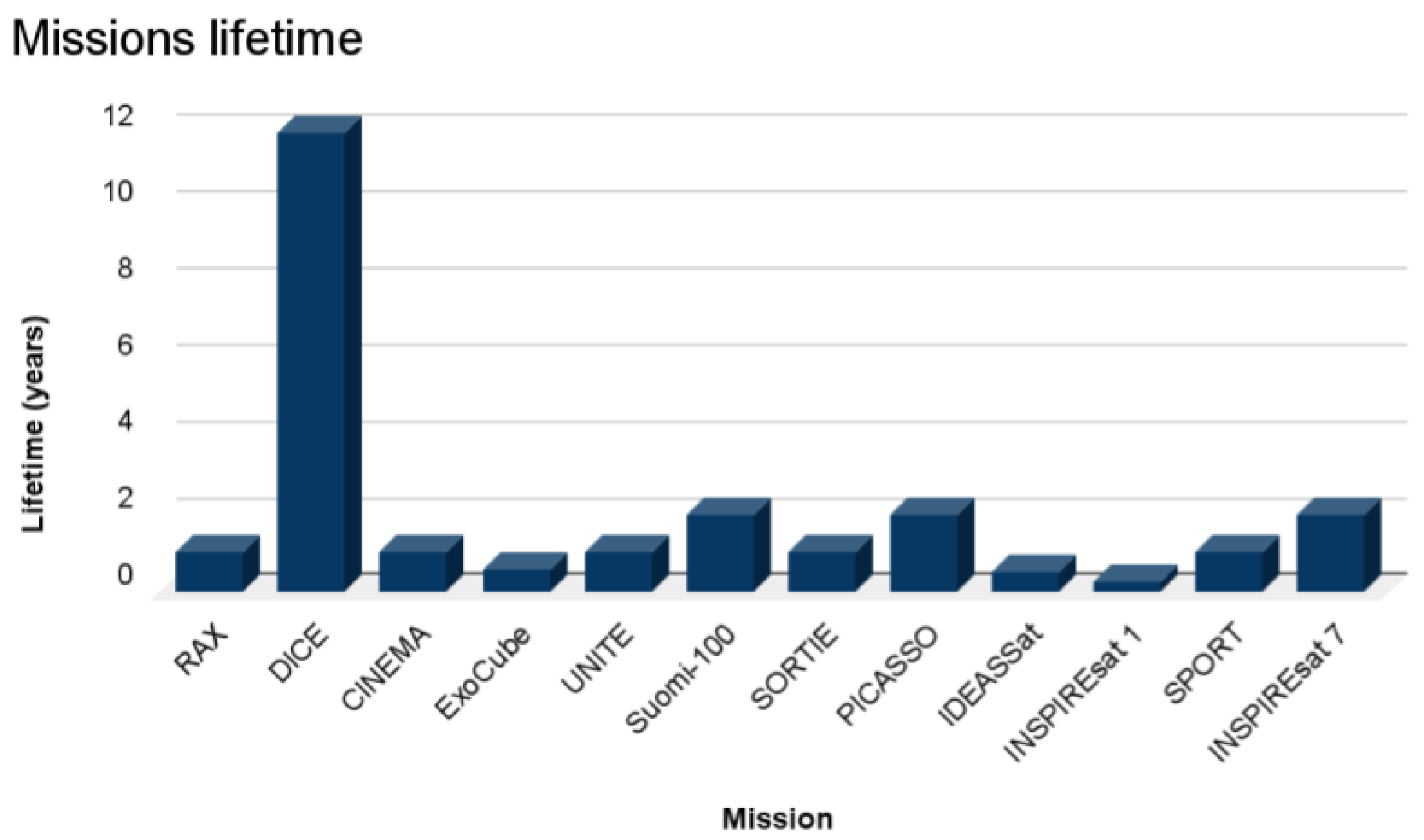
This section reviews CubeSat missions launched to study the ionosphere. The focus is on their scientific goals and the payload and orbit used to achieve them. Table 1 summarizes some key parameters of the missions mentioned in this paper: their size, launch year, mean lifetime expected (also represented in Figure 2), and the orbit they were put in.
More CubeSat missions are being developed and improved, not only for educational purposes at universities, but also by the industry as the exploration technology is spreading and evolving.
Despite the many CubeSat missions already set up for the study of the ionosphere, as detailed in Table 1, the data from these missions is scarce and in general is not accessible.
3.1. RAX (Radio Aurora Explorer)
The RAX mission(https://www.eoportal.org/satellite-missions/rax (accessed on 15 June 2023)) has two satellites, RAX-1 [47] and RAX-2 [48], launched in November 2010 and October 2011, respectively, into a circular orbit (Table 2) [49]. It was the first nanosatellite mission funded by the National Science Foundation (NSF) and it was a collaboration between SRI International and the Michigan Exploration Laboratory (MXL) at the University of Michigan. The designs of both satellites are identical with the exception of the solar panels since those of RAX-1 failed after one month, causing its end [47].
This mission is a based ground-to-space bi-static radar experiment designed to study the field-aligned irregularities (FAI), which translates into studying the plasma instabilities that lead to magnetic field-aligned irregularities of electron density. These irregularities are capable of disrupting communication and navigation signals. These FAI measurements are enabled by its primary payload, a UHF radar receiver [50] designed to operate with five UHF megawatt-class incoherent scatter radars (ISR) on the ground [49,51].
3.2. DICE (Dynamic Ionosphere CubeSat Experiment)
The DICE mission (https://sites.erau.edu/sail/dice/ (accessed on 15 June 2023)) has a two-spacecraft constellation of two 1.5U CubeSat of 10 × 10 × 15 cm each, both spin-stabilized which allows simultaneous measurements of electric field and electron density [34].
DICE is a constellation to observe the Sun-to-Earth system by addressing questions about the Storm Enhanced Density (SED) [52]. This translates into understanding what physical processes are responsible for the formation of the SED bulge in the noon to the post-noon sector during magnetic storms and for the formation of the SED plume at the base of the SED bulge. It also aims to study the transport of the high-density SED plume across the magnetic pole and investigate the relationship between the Prompt Penetration Electric (PPE) fields and the formation and evolution of SED [34].
To accomplish these goals, the satellite’s payload consists of three main instruments as listed in Table 3.
This mission was launched in October 2011, into a nearly Sun-synchronous orbit with the parameters displayed in Table 4.
The DICE mission is a collaborative effort between industry and universities, funded by NSF and NASA Educational Launch of Nanosatellites (ELaNa), implemented by university undergraduate and graduate students. One of the institutions involved, Utah State University/Space Dynamics Laboratory (USU/SDL), maintains a data center (DC) with the data acquisitions being stored in a MySQL database [53].
3.3. TRIO-CINEMA (Triplet Ionospheric Observatory—Cubesat for Ion, Neutral, Electron and MAgnetic Fields)
TRIO-CINEMA (http://sprg.ssl.berkeley.edu/cinema/ (accessed on 15 June 2023)) is a constellation with three CubeSats that aims to perform space weather measurements, namely high sensitivity Electron Neutral Atoms (ENA) mapping and electron and ion measurements in the auroral and ring current precipitation regions [54].
To accomplish these goals, the satellite’s payload consists of two main instruments, as listed in Table 5.
CINEMA-1 was launched in September 2012 and CINEMA-2/3 were launched in November 2013, all into a Sun-synchronous orbit (Table 6) [56].
The first CubeSat of this constellation was developed by the Space Sciences Laboratory at the University of California, Berkeley (UCB/SSL), along with NASA Ames Research Center and the Imperial College London (ICL), funded by the National Science Foundation (NSF). The other two were made by Kyung Hee University (KHU) under its World Class University (WCU) program [54].
3.4. ExoCube
ExoCube is a space weather nanosatellite with the goal of performing in situ measurements of species densities in the Earth’s lower exosphere and upper ionosphere (Table 7) [58].
This satellite is a 3U CubeSat [60] that was launched in January 2015 into a Sun-synchronous orbit (Table 8), and it was predicted to operate for 6 to 12 months, but ended up operating for approximately 7 months [61].
The mission was predicted to operate for 6 to 12 months. However, failure in the deployment of an antenna led to problems in the communication system, and the mission operated only for approximately 7 months. After a redesign of the antenna deployment mechanisms, a second satellite was launched in 2017, named ExoCube 2, to perform the same scientific mission [59].
This mission is a consortium between California Polytechnic State University, NASA’s Goddard Space Flight Center, and the University of Wisconsin.
3.5. UNITE (Undergraduate Nano Ionospheric Temperature Explorer)
The UNITE (Undergraduate Nano Ionospheric Temperature Explorer) mission has the goal of measuring plasma properties in the lower ionosphere (Table 9), measuring the satellite’s internal and skin temperatures, and recording the orbital decay of the satellite. UNITE was launched in December 2018 into a circular orbit (Table 10) [63].
This satellite was developed by an all-undergraduate team at University of Southern Indiana (USI) [63].
3.6. Suomi-100
Suomi-100 (https://www.suomi100satelliitti.fi/index_eng.html (accessed on 15 June 2023)) is a 1U CubeSat, launched in December 2018 into a Sun-synchronous orbit (Table 11) [64].
The scientific goal of this mission is to study the ionosphere and the auroras, using the instruments listed in Table 12, combined with ground-based instruments [64,65].
This mission was built by the Aalto University, Finland, and GOMSpace in order to commemorate the 100th anniversary of Finland in 2017 [66].
3.7. SORTIE (Scintillation Observations and Response of the Ionosphere to Electrodynamics)
SORTIE (https://www.eoportal.org/satellite-missions/sortie (accessed on 15 June 2023)) is a 6U CubeSat of 10 × 20 × 30 cm with the goal to make in situ measurements of plasma density and ion drift in order to understand the spectrum of wave perturbations causing the plasma instabilities, mainly in the F-region of the ionosphere [67].
To accomplish those goals, the satellite’s payload consists of three main instruments as listed in Table 13.
The SORTIE mission is a consortium between industry and universities and it was launched in December 2019 into a near-circular orbit (Table 14), with 1 year of on-orbit lifetime [67].
Results of the first 60 h of IVM on-orbit, which were found to be fitting for characterization of the thermal plasma in the ionosphere, are presented in [67]. The first measurements of a Traveling Ionospheric Disturbance (TID) are presented in [68]. An atmospheric model is applied in [69] to interpret SORTIE measurements.
3.8. PICASSO (Pico-Satellite for Atmospheric and Space Science Observations)
PICASSO (https://directory.eoportal.org/web/eoportal/satellite-missions/p/picasso (accessed on 15 June 2023)) is a 3U CubeSat science mission, launched in September 2020, with two scientific instruments (Table 15) and it aims to determine the ozone distribution in the stratosphere, the temperature profile up to the mesosphere, and the electron density in the ionosphere [70].
Regarding the measurement of the electron density and temperature in the ionosphere, PICASSO uses a Sweeping multi-needle Langmuir Probe, formed by 4 cylindrical Langmuir probes at the edge of solar panels. This Langmuir probe allows the study of the ionosphere–plasmasphere coupling, the aurora structure, ionosphere and magnetospheric features, and the ionospheric dynamics [71,72].
To accomplish those goals, it should be flying through the upper layers of the ionosphere, which translates into a high inclination low-Earth orbit (LEO) (Table 16) with a lifetime of at least 2 years [72].
The PICASSO mission is a project initiated by the Belgian Institute for Space Aeronomy (BISA) and then became under the administration of the European Space Agency (ESA) within the frame of the General Support Technology Programme (GSTP) and of the Technology Research Programme (TRP). This consortium also includes Clyde-Space Ltd. (UK), VTT (Finland), and The Centre Spatial of Liège (Belgium) [72].
3.9. IDEASSat (Ionosphere Dynamics Explorer and Attitude Subsystem Satellite)
IDEASSat (http://www.ss.ncu.edu.tw/~ssoffice/ (accessed on 15 June 2023)) (Ionosphere Dynamics Explorer and Attitude Subsystem Satellite) is a 3U CubeSat mission with the purpose to take in situ measurements of ionospheric variability and irregularities to comprehend their effects on satellite navigation signals and radio communications [73].
To achieve these goals, the science payload of this mission is called a Compact Ionospheric Probe (CIP) and its instruments are listed in Table 17.
The IDEASSat is a mission executed by Taiwan National Central University (NCU) with the collaboration of the International Satellite Program in Research and Education (INSPIRE) consortium [73]. Although it had a one and half month communications blackout due to a critical anomaly 22 days after launch, the flight data recovered will help to improve the designs of future spacecrafts [75].
3.10. INSPIREsat 1 (International Satellites Program in Research and Education Satellite-1)
The INSPIREsat 1 (https://lasp.colorado.edu/inspire/ (accessed on 15 June 2023)) is a 9U CubeSat, launched in February 2022 [76] with two scientific instruments (Table 19): a Dual Aperture X-ray Solar spectrometer (DAXSS) to measure Solar soft X-rays of keV to 20 keV, and a Compact Ionosphere Probe (CIP) which is a 4-in-1 plasma sensor that allows the characterization of the temporal and spatial distributions of small-scale plasma irregularities in the ionosphere [77]. Associated with these two main instruments are two main scientific goals [77]: describe plasma properties and variations within the ionosphere at low and mid-latitudes, and enhance our comprehension of the mechanisms responsible for heating the Sun’s corona through the measurement of the Sun’s soft X-ray spectrum.
This mission was launched into a Sun-synchronous orbit with the parameters displayed in Table 20.
INSPIRESat 1 is a collaboration between students from National Central University (NCU Taiwan) and Taiwan’s National Space Organization (NSPO), also including the Indian Institute of Space Science and Technology (IIST), the University of Colorado’s Laboratory for Atmospheric & Space Physics (LASP), and the Singapore’ Nanyang Technological University.
3.11. SPORT (Scintillation Prediction Observations Research Task)
SPORT (Scintillation Prediction Observations Research Task) is a 6U CubeSat mission, launched in November 2022 into a near-circular orbit (Table 21) [78,79].
This mission aims to further comprehend the formation of plasma bubbles in the ionosphere and how they affect the propagation of electromagnetic waves and signals [80,81]. To accomplish those goals, the satellite’s payload is listed in Table 22.
The SPORT mission is the result of a collaborative effort between NASA, the Brazilian National Institute for Space Research (INPE), and the Technical Aeronautics Institute under the Brazilian Air Force Command Department (DCTA/ITA) [80].
3.12. INSPIREsat 7 (Ionospheric Dynamics Explorer and Attitude Subsystem Satellite 7)
The INSPIREsat 7 mission was launched in April 2023 [82] into a Sun-synchronous orbit at 600 km altitude [83].
Although the main goal of this mission is to measure the Earth’s radiation budget at the top of the atmosphere for climate change studies, it also has the objective to study the ionosphere using the CUIONO1 Payload to [83]:
- Help improve the International Reference (IRI) model;
- Further comprehend the behavior of electromagnetic waves as they propagate through the ionosphere;
- Comprehend the variations in time and space across multiple scales;
- Investigate the interaction between the ionosphere and magnetosphere, and between the ionosphere and lithosphere.
It also uses a new approach by combining a ground-based High-Frequency (HF) transmitter with an HF receiver on board the satellite. Throughout its trajectory, the attenuation of HF waves as they pass through the ionosphere will be quantified whenever it is within range of the ground transmitter. This allows monitoring the state of the ionosphere since the radio wave propagation depends on its electron density [83,84].
INSPIREsat 7 was developed by students from the Université de Versailles Saint-Quentin-en-Yvelines (UVSQ) helped by the International Satellite Program in Research and Education (INSPIRE).
4. Instrumentation
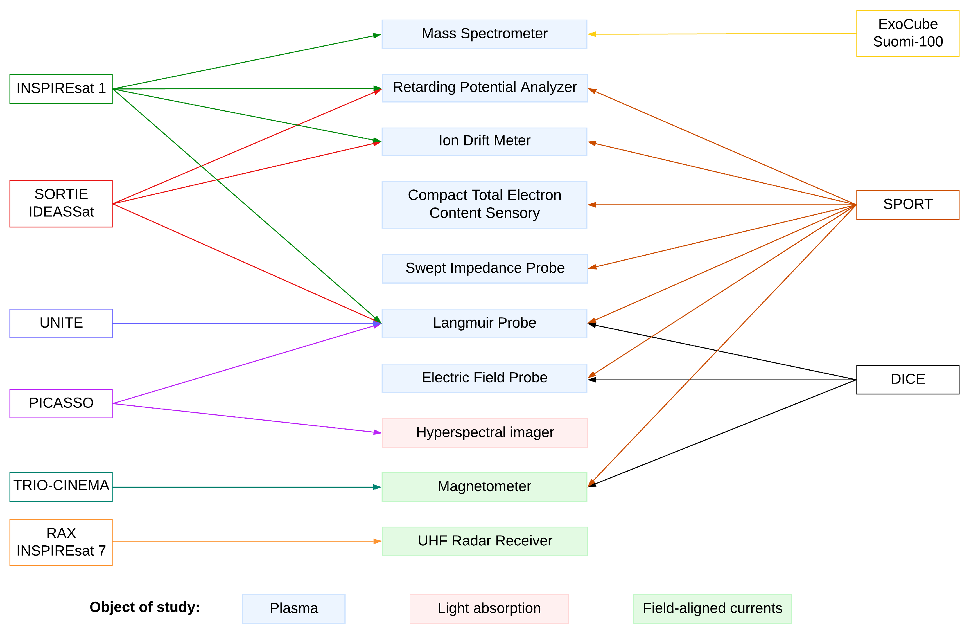
All CubeSats have five common subsystems: Electric Power System (EPS), On-Board Computer (OBC), Communication system (COM), Attitude Determination and Control System (ADCS), and Support Structure [23]. Adding to these subsystems, all CubeSats have a payload that depends on the scientific objectives of their particular mission. Taking the missions analyzed in Section 3, we can group their payload according to the main target measurements, as shown in Figure 3. A review of the main sensors used for plasma diagnostics such as Langmuir probes (LP), retarding potential analyzers (RPA), and ion drift meters, among others, is provided by [85].
The specific instruments used for each mission have been mentioned in Section 3. Here, we give a general overview of some of the most common techniques to study the ionosphere.
4.1. Langmuir Probe
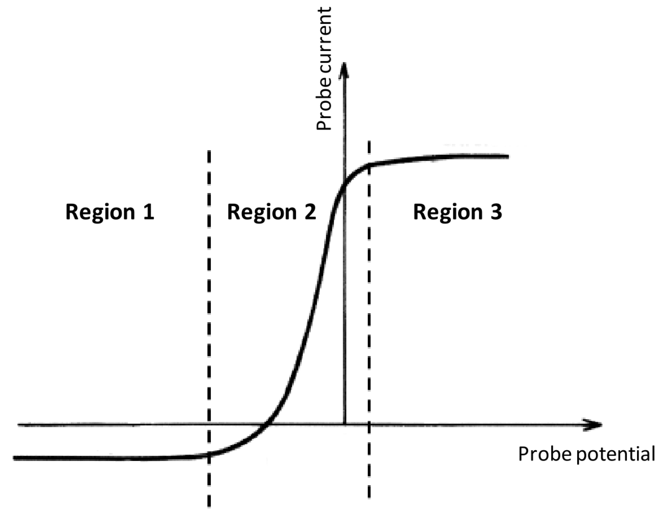
Langmuir probes (LP) working principle is the single probe method (SPM), based on the electrostatic probe theory developed by Irving Langmuir and Mott-Smith [86,87]. This method consists in doing in situ measurements of stationary or slowly time-varying plasmas parameters by immersing in it a conductor with a bias voltage applied to it, assuming ions as single charge cold particles and electrons as having a Maxwellian velocity distribution. By varying the bias voltage, the current measured will be different, and that current-voltage (I-V) relation is characteristic of each LP (Figure 4). The sensor is a single electrode that can be a plane, cylindrical, or spherical [86,88,89].
Regarding the measurements possible with this kind of probe, each region of the I–V curve (Figure 4) has its role [86,89,90]:
- Region 1: ions are collected and electrons repelled, allowing us to determine the ion density and temperature of the plasma.
- Region 2: both ions and electrons are attracted towards the probe and the electron temperature can be determined through the slope of the exponential.
- Region 3: electrons are attracted and ions repelled, allowing us to determine the electron density of the plasma.
Another variation of the classic use of the Langmuir probe is the multi-needle Langmuir probe (m-NLP). This instrument has four individual probes (needles), each one smaller than the Debye length, providing higher resolution for small-scale ionospheric plasma density structures [91,92].
Of all the instrumentation payloads on ionospheric CubeSat missions, the Langmuir probe is the most common due to its ability to measure the main ionospheric plasma parameters, i.e., electron density and temperature.
4.2. Retarding Potential Analyzer
A retarding potential analyzer (RPA) is a type of electrostatic analyzer [93] that works based on the Debye length, i.e., based on the distance that an electrostatic charge can significantly influence a particle. This length depends on the electrons’ temperature and density and defines the spacing between grids. The RPA is then a series of conductive grids (electrodes) parallel to each other and perpendicular to the direction of motion of the satellite [94,95].
After passing the grids, the ions arrive at the detector and strip off electrons, creating a current. In order to be able to use RPAs for ionospheric studies, there are some assumptions that need to be made, namely [94,95]:
- Ions are in thermal equilibrium.
- Grids are infinitesimally thin.
- Potential distribution completely flat across the grid’s surfaces.
- Negligible effects of non-uniform potential surfaces.
- The ions’ thermal velocity is much smaller than the satellite velocity, which means they enter the aperture as a supersonic beam.
- The aperture is smaller than the collector surface, allowing the measurement of particles that arrive at small angles relative to the grid’s normal direction.
In the RPA, one of its internal grids is swept over a range of voltages to work as a retarding grid, and by analyzing the current-voltage characteristic (i.e., total ion flux as a function of retarding voltage) of the instrument, it is possible to measure the ion temperature, plasma density, the component of the ion velocity along the orbit-track, and the ratio of light ions (H+, He+) to heavy ions (O+, NO+, …) [94,95,96].
However, retarding potential analyzers have limitations regarding the characterization of the ions drift vectors, which leads to the use of ion drift meters (Section 4.3).
4.3. Ion Drift Meter
As stated before, the limitation of the retarding potential analyzers on the characterization of the ions drift vectors leads to the need to use an ion drift meter (IDM). Just like a RPA, an ion drift meter (IDM) is a stack of parallel conductive grids; however, it has a diaphragm and a segmented collector electrode. It is a device used to take in situ measurements of the plasma, particularly ion velocity (used to determine the ion drift) and when used along with a Magnetometer (Section 4.4), it allows us to estimate the local electric field [85,96].
The working principle is very similar to the RPA’s: the ions pass through an opening at the front and the currents produced at the collector are measured. The IDM has a grounded grid exposed to the plasma that faces the ram direction. The velocity of the satellite is assumed to be larger than the ions’ thermal velocity. However, the collector of the ion drift meter is segmented into four squares allowing to determine an angle of incidence through the ratio of the ram to cross-track speeds [85,96,97]. This angle is given by
where W is the width of the aperture, D is the distance between the collector plates and the aperture, and and are the currents measured by adjacent collector plate halves [97]. Through this arriving angle, it is possible to determine the transverse velocity [97]:
with:
- : spacecraft velocity;
- : relative velocity of ions with respect to the sensor along the satellite track;
- q: fundamental unit charge;
- : spacecraft potential;
- : ion mass.
4.4. Magnetometer
Magnetometers can be divided into two categories: scalar and vector magnetometers. Scalar magnetometers measure the strength or magnitude of the magnetic field and vector magnetometers provide directional information, which makes them more useful for space missions [98,99].
Within the various options of vector magnetometers, fluxgate magnetometers are the most common for space applications, with the mass and power requirements being the main advantages of it [99,100]. This instrument consists of a ferromagnetic core wrapped with two sets of coils: the drive coil that drives the core into and out of saturation, and the sense coil that senses the induced effect [101,102]. There is an alternating magnetic field in the core, induced by the alternate current applied to the drive coil, driving the core into saturation. When in the presence of an external magnetic field, the saturation of the core deflects in one direction. This deflection causes an asymmetry between the drive and sense currents, proportional to the magnitude of the external magnetic field [100].
Regarding its sensitivity, the maximum is achieved when the magnetic field-magnetic induction (B-H) is square. This means that the induced electromotive force (emf) is the biggest for a given value of the magnetic field [101].
4.5. Radio Occultation
The radio occultation technique (e.g., [103,104,105]) provides an efficient tool for global profiling of the ionosphere. It consists of having transmitters on GPS satellites and GPS receivers on low Earth orbit (LEO) satellites located on the opposite sides of the planetary limb, providing high precision and vertical resolution at long wavelengths that penetrate through the atmosphere in nearly all conditions [106].
The reception of multi-satellite navigation signals, affected by their travel path through the ionosphere, provides key information on the ionospheric state. Satellite missions with a GNSS receiver onboard enable permanent monitoring of the Earth’s co-rotating plasma environment, (e.g., [106]). Dedicated constellations ([107] enable a thorough characterization of the state of the ionosphere.
For the missions considered in this paper, SPORT (Section 3.11) uses the Compact Total Electron Content Sensor (CTECS), which is a GPS occultation sensor to gather electron density profiles at low latitudes and to detect the presence of scintillation [78].
5. Orbits
The orbits of satellite missions for the study of the Earth are divided into five main groups: Geostationary Earth Orbit (GEO), Low Earth Orbit (LEO), Medium height Earth Orbit (MEO), Highly Elliptical Orbit (HEO), and Non-geocentric orbits such as Lagrange points or interplanetary. Each of these orbits has specifications regarding altitude, position relative to Earth, and communication system with the ground, among others. The CubeSat missions described in Section 3 have different orbits, depending on their goals. However, since they all aim to study the ionosphere, all of their orbits are LEO, i.e., with an altitude below 2000 km. Table 1 shows that the most used orbits are circular and Sun-synchronous. Sun-synchronous orbit (SSO) is a polar near-circular Low-Earth Orbit (LEO) [108]. Satellites in this type of orbit are synchronous with the Sun, i.e., they always have the same position relative to the Sun. Although this is a type of orbit frequently used for earth science missions, sometimes it is quite challenging to choose the orbit parameters, and Ref. [109] is a step-by-step guide on how to accomplish it.
Different tools are available today that can model the orbit of a satellite depending on the orbital parameters. Examples include the online platform SPENVIS from the Royal Belgian Institute for Space Aeronomy (https:/www.spenvis.oma.be/ (accessed on 15 June 2023)), the Matlab Aerospace Toolbox (https://www.mathworks.com/products/aerospace-toolbox.html (accessed on 15 June 2023)), the Ansys Systems Tool Kit STK (https://www.ansys.com/products/missions/ansys-stk (accessed on 15 June 2023)) and FreeFlyer (https://ai-solutions.com/freeflyer-astrodynamic-software/ (accessed on 15 June 2023)).
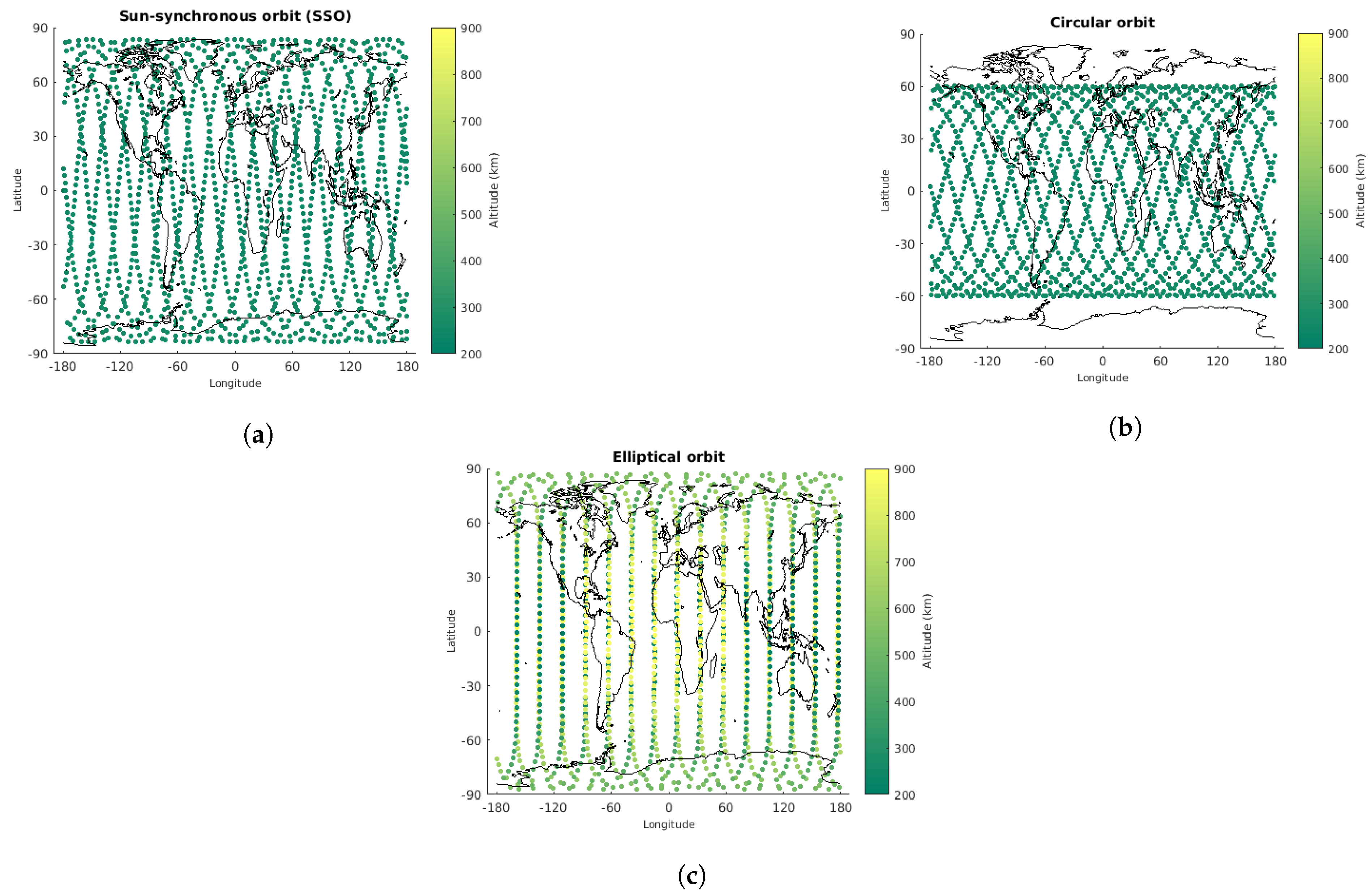
Different types of orbits have different applications, and they should be defined based on mission requirements that are unique to each mission. An example of each type of orbit is shown in Figure 5.
Sun-synchronous orbit (SSO) is a polar near-circular Low-Earth Orbit (LEO) [108]. Satellites in this type of orbit are synchronous with the Sun, i.e., they always have the same position relative to the Sun. Although this is a type of orbit frequently used for Earth science missions, sometimes it is quite challenging to choose the orbit parameters, and Ref. [109] is a step-by-step guide on how to accomplish it.
6. Data and Metadata
Despite the exploratory nature of many CubeSat missions, data acquisition and data management play a critical role. Even if CubeSats are deployed just for testing purposes (e.g., of a new payload or satellite component) the retrieval of data is fundamental to assess the behavior of the assets under consideration and further scientific exploration of CubeSat measurements.
Not only data but metadata—data about data—is fundamental to enhance the usefulness of CubeSat missions. By their nature, most space missions are not limited to the collection of a single data theme, but include several although often interrelated data themes. Each theme can be divided by temporal, geographical, or other criteria, designated as a resource. The metadata characterizing a resource should at least provide information on [110]:
- What it is and what it refers to.
- Why it was built or carried out, to what purpose it was created.
- When it was produced, published, or updated.
- Who created, supported, or developed it.
- How it was collected, produced, it is reliable, how to access it.
- Where it refers to, what area, in what geography, or position.
Metadata improves data management by allowing the information to be cataloged in a standard way so that it is searchable and comparable. Three levels of metadata are typically considered: discovery, exploration and exploitation [111]. Discovery metadata aims to classify or reference, allowing data to be searched and found in the midst of other data sets. Exploration metadata aims to add detailed information about the quality, accuracy, and origin of the data. Exploitation metadata explains how to read, transfer and integrate data into applications. These levels have no rigid borders, and some directives, e.g., Ref. [112], refer to only discovery and interoperability metadata.
The INSPIRE framework for metadata presents a comprehensive and parameterized view. That is evident in the way it proposes how the theme/keywords are chosen and indexed, as well as in the care to fulfill the terms/values for the compliance degree of the resource, through the listing of standards and publications, as themselves, as part of the reference in the metadata.
The ISO core metadata elements for spatial dataset and spatial dataset series, propounds the dataset title, the dataset reference date (publication, revision, or creating), the responsible party (organization name and email contact address), the dataset language, the dataset character set, the dataset topic category, the metadata file identifier (plus name and version), the metadata language and character set. The INSPIRE propounds many other demanding attributes, and a specific directive [113] of the European Parliament and Council on the interoperability of spatial data sets and services.
There are two topics to emphasize. One is, that even these rich standards, do not have a specific attribute to record the answer to why it was built or carried out.
The other is the care to clearly define three degrees of compliance about a resource and to enforce that assessment is based on a document, a standard, a citation, being able to take only these values:
- Conformant—the resource fully complies with the stated specification.
- Not conformant—the resource does not conform to the referenced specification.
- Not evaluated—the compliance has not been assessed.
It is precisely the fact that a resource is compliant that renders it the value to be used by the scientific community [114]. Also, it is still necessary that the resource be accessible, through well-known (public) formats and structured in such a way that the research and information extraction is not hidden by technical or reproducibility difficulties.
The adoption of a data standard might broaden the reach of scientific information, to a larger community, and even to the citizen. Filling some of the core tables of a data model might assist and guide to improve the CubeSat mission objectives definition, in particular by focusing on which variables are intended to be measured, which methods of measurement (and respective instruments will be applied), which people and institutions will be responsible, which actions and the sequence of actions will be adopted before and during in the mission, and what and how the information will be available during and after the mission.
Currently, space agencies have an open data policy, aiming to facilitate the broadest use of its contents. For example, NASA has an open data policy for Earth exploration (https://www.earthdata.nasa.gov/learn/articles/nasa-earth-science-data-yours-use-fully-and-without-restrictions (accessed on 15 June 2023)), and ESA has a policy of free and open access to its contents (https://open.esa.int/ (accessed on 15 June 2023)). However, CubeSat missions typically involve cooperation between diverse educational institutions and often include a heterogeneous mix of universities, companies, and other stakeholders. While for space agencies it is straightforward to clear access to content it fully owns, in the case of a heterogeneous consortium third-party rights have to be cleared and an open data policy might not be a priority. This could partly explain the lack of accessible data from the diverse CubeSat missions considered in this review.
7. Ionospheric Models
The Ionospheric Models parameterize the behavior of both electron and ion densities and temperatures in space and time. They can be used to identify regions of interest according to the scientific goals of the mission, helping to plan its orbiting parameters. On the other hand, all ionospheric missions can help to improve the accuracy of the models with the data they collect. There are several Ionospheric Models, for example:
- The International Reference Ionosphere (IRI) model (https://irimodel.org/ (accessed on 15 June 2023)) [119] is an empirical model primarily based on observational data, synthesizing almost all available and reliable ionospheric data from both ground and space data sources.
- The NeQuick model [120] and its subsequent updated versions, Refs. [121,122] is an analytical model of the electron density of ionosphere above 90 km and up to the peak of the F2 layer. For a given location, time, and solar conditions (solar flux or sunspot number) the model returns the electron concentration, enabling us to evaluate the electron density along any ground-to-satellite ray-path and the corresponding total electron content (TEC) by numerical integration.
- The NRLMSISE-00 Atmospheric Model is an empirical representation of Earth’s atmosphere, spanning from the Earth’s surface to outer space, and it models the temperatures and densities of the atmosphere’s components [123].
The IRI model is the most commonly used. It is possible to simulate multiple model parameters for a given time and location. This model is also used to help plan CubeSat missions. For example, Ref. [124] uses IRI data to study how a Langmuir probe will be affected by the magnetic field orientation. So far, ionospheric models are being used to plan the missions and simulate the behavior of satellites.
Regarding the ionospheric missions listed in Section 3, there are no data available and their contribution to existing ionospheric models are yet to be found. The exception is the DICE mission, as Ref. [35] shows that the measurements of the Langmuir Probes match the predictions from ionospheric models.
8. Conclusions
There are many ionospheric CubeSat missions already in place and many others are currently in their planning stages. CubeSats have a tremendous potential to foster ionospheric studies, improving our understanding of Space Weather and its effects on space and surface infrastructures.
However, there is still a lack of documentation for ionospheric CubeSat missions, especially with regard to the data and metadata. Hopefully, as this is a technology that is still evolving, teams will start to document more and better, allowing those who come later to have a greater basis for comparison and even use the data to improve existing ionospheric models. Adequate data management and ensuring fair data from CubeSat missions should be a priority for ongoing and future Cubesat missions.
Author Contributions
Conceptualization, C.F. and S.B.; investigation, C.F. and R.H.; writing—original draft preparation, C.F. and R.H.; writing—review and editing, C.F., R.H. and S.B.; visualization, C.F.; supervision, S.B. All authors have read and agreed to the published version of the manuscript.
Funding
This research was funded by the Portuguese Foundation for Science and Technology (FCT) LA/P/0063/2020.
Data Availability Statement
No new data were created or analyzed in this study. Data sharing is not applicable to this article.
Acknowledgments
This work is funded by Fundação para a Ciência e Tecnologia LA/P/0063/2020 with support from the NewSat project (Development of a compact integrated sensor and satellite for Earth observation) under the MIT-Portugal program.
Conflicts of Interest
The authors declare no conflict of interest.
References
- North, G.R.; Pyle, J.A.; Zhang, F. Encyclopedia of Atmospheric Sciences. 2014. Available online: https://www.sciencedirect.com/referencework/9780123822253/encyclopedia-of-atmospheric-sciences (accessed on 14 June 2023).
- Liu, J.; Wang, W.; Qian, L.; Lotko, W.; Burns, A.G.; Pham, K.; Lu, G.; Solomon, S.C.; Liu, L.; Wan, W.; et al. Solar flare effects in the Earth’s magnetosphere. Nat. Phys. 2021, 17, 807–812. [Google Scholar] [CrossRef]
- Kelley, M.C. The Earth’s Ionosphere: Plasma Physics and Electrodynamics; Academic Press: Cambridge, MA, USA, 2009. [Google Scholar] [CrossRef]
- Nishimura, Y.; Deng, Y.; Lyons, L.R.; McGranaghan, R.M.; Zettergren, M.D. Multiscale dynamics in the high-latitude ionosphere. In Ionosphere Dynamics and Applications; Wiley Online Library: Hoboken, NJ, USA, 2021; pp. 49–65. [Google Scholar] [CrossRef]
- Lyon, J.G. The solar wind-magnetosphere-ionosphere system. Science 2000, 288, 1987–1991. [Google Scholar] [CrossRef] [PubMed]
- Immel, T.J.; England, S.; Mende, S.; Heelis, R.; Englert, C.; Edelstein, J.; Frey, H.; Korpela, E.; Taylor, E.; Craig, W.; et al. The ionospheric connection explorer mission: Mission goals and design. Space Sci. Rev. 2018, 214, 1–36. [Google Scholar] [CrossRef] [PubMed]
- Heelis, R.; Maute, A. Challenges to understanding the Earth’s ionosphere and thermosphere. J. Geophys. Res. Space Phys. 2020, 125, e2019JA027497. [Google Scholar] [CrossRef]
- Singh, A.; Siingh, D.; Singh, R. Space weather: Physics, effects and predictability. Surv. Geophys. 2010, 31, 581–638. [Google Scholar] [CrossRef] [Green Version]
- Schwenn, R. Space weather: The solar perspective. Living Rev. Sol. Phys. 2006, 3, 1–72. [Google Scholar] [CrossRef]
- Schrijver, C.J.; Kauristie, K.; Aylward, A.D.; Denardini, C.M.; Gibson, S.E.; Glover, A.; Gopalswamy, N.; Grande, M.; Hapgood, M.; Heynderickx, D.; et al. Understanding space weather to shield society: A global road map for 2015–2025 commissioned by COSPAR and ILWS. Adv. Space Res. 2015, 55, 2745–2807. [Google Scholar] [CrossRef]
- Berdermann, J.; Kriegel, M.; Banyś, D.; Heymann, F.; Hoque, M.; Wilken, V.; Borries, C.; Heßelbarth, A.; Jakowski, N. Ionospheric response to the X9.3 flare on 6 September 2017 and its implication for navigation services over Europe. Space Weather 2018, 16, 1604–1615. [Google Scholar] [CrossRef] [Green Version]
- Goodman, J.M. Operational communication systems and relationships to the ionosphere and space weather. Adv. Space Res. 2005, 36, 2241–2252. [Google Scholar] [CrossRef]
- Basu, S.; Basu, S.; Makela, J.; MacKenzie, E.; Doherty, P.; Wright, J.; Rich, F.; Keskinen, M.; Sheehan, R.; Coster, A. Large magnetic storm-induced nighttime ionospheric flows at midlatitudes and their impacts on GPS-based navigation systems. J. Geophys. Res. Space Phys. 2008, 113, A3. [Google Scholar] [CrossRef] [Green Version]
- Astafyeva, E.; Yasyukevich, Y.; Maksikov, A.; Zhivetiev, I. Geomagnetic storms, super-storms, and their impacts on GPS-based navigation systems. Space Weather 2014, 12, 508–525. [Google Scholar] [CrossRef]
- Xiang, Y.; Gao, Y. An enhanced mapping function with ionospheric varying height. Remote Sens. 2019, 11, 1497. [Google Scholar] [CrossRef] [Green Version]
- Pirjola, R. Space weather effects on power grids. In Space Weather—Physics and Effects; Springer: Berlin/Heidelberg, Germany, 2007; pp. 269–288. [Google Scholar] [CrossRef]
- Marshall, R.; Dalzell, M.; Waters, C.; Goldthorpe, P.; Smith, E. Geomagnetically induced currents in the New Zealand power network. Space Weather 2012, 10. [Google Scholar] [CrossRef]
- Pirjola, R.; Pulkkinen, A.; Viljanen, A. Studies of space weather effects on the Finnish natural gas pipeline and on the Finnish high-voltage power system. Adv. Space Res. 2003, 31, 795–805. [Google Scholar] [CrossRef]
- Breus, T.; Ozheredov, V.; Syutkina, E.; Rogoza, A. Some aspects of the biological effects of space weather. J. Atmos. Sol.-Terr. Phys. 2008, 70, 436–441. [Google Scholar] [CrossRef]
- Mavromichalaki, H.; Papailiou, M.; Dimitrova, S.; Babayev, E.; Loucas, P. Space weather hazards and their impact on human cardio-health state parameters on Earth. Nat. Hazards 2012, 64, 1447–1459. [Google Scholar] [CrossRef]
- Wu, S.; Chen, W.; Cao, C.; Zhang, C.; Mu, Z. A multiple-CubeSat constellation for integrated earth observation and marine/air traffic monitoring. Adv. Space Res. 2021, 67, 3712–3724. [Google Scholar] [CrossRef]
- Kulu, E. Nanosatellite Launch Forecasts-Track Record and Latest Prediction. 2022. Available online: www.nanosats.eu (accessed on 21 June 2023).
- Lukkari, J. Automated Functional System Integration Testing of Suomi 100 Satellite. Master’s Thesis, Aalto University, Espoo, Finland, 2018. Available online: https://space.aalto.fi/pdf/Lukkari_s100_thesis_20180522.pdf (accessed on 15 June 2023).
- Swartwout, M. CubeSats and Mission Success: 2017 Update. In Proceedings of the Electronic Technology Workshop, NASA Electronic Parts and Packaging Program (NEPP), NASA Goddard Space Flight Center; Greenbelt, MD, USA, 27 June 2017, Volume 27. Available online: https://nepp.nasa.gov/workshops/etw2017/talks/28-JUN-WED/0900%20-%20swartwout%20etw%202017.pdf (accessed on 15 June 2023).
- Alkalai, L.; Norton, C.; Freeman, A. CubeSats and Small Satellites as a Vehicle for Space Innovation and Exploration of Space Beyond Earth Orbit. In Proceedings of the 4th IAA Conference on University Satellite Missions and CubeSat Workshop, Roma, Italy, 4–7 December 2018; Available online: https://www.gaussteam.com/wordpress/wp-content/uploads/2018/02/20171204_Leon-Alkalai-1.pdf (accessed on 14 June 2023).
- Bandyopadhyay, S.; Subramanian, G.P.; Foust, R.; Morgan, D.; Chung, S.J.; Hadaegh, F. A review of impending small satellite formation flying missions. In Proceedings of the 53rd AIAA Aerospace Sciences Meeting, Kissimmee, FL, USA, 5–9 January 2015; p. 1623. [Google Scholar] [CrossRef] [Green Version]
- Poghosyan, A.; Golkar, A. CubeSat evolution: Analyzing CubeSat capabilities for conducting science missions. Prog. Aerosp. Sci. 2017, 88, 59–83. [Google Scholar] [CrossRef]
- Rastinasab, V.; Hu, W.; Tahmasebi, M.K. Water Recognition on the Moon by Using THz Heterodyne-Spectrometer for Identifying the Appropriate Locations to Extract Water for Providing Oxygen for Breathing and Fuel for Spaceships’ Propulsion on the Moon with CubeSat. Aerospace 2021, 8, 186. [Google Scholar] [CrossRef]
- Maj, R.; Cairns, I.H. Dust detection via voltage power spectroscopy on a CubeSat in Earth’s ionosphere. J. Geophys. Res. Space Phys. 2018, 123, 7871–7888. [Google Scholar] [CrossRef]
- Robson, D.J.; Cappelletti, C. Biomedical payloads: A maturing application for CubeSats. Acta Astronaut. 2022, 191, 394–403. [Google Scholar] [CrossRef]
- Dandouras, I.; Blanc, M.; Fossati, L.; Gerasimov, M.; Guenther, E.W.; Kislyakova, K.G.; Lammer, H.; Lin, Y.; Marty, B.; Mazelle, C.; et al. Future Missions related to the determination of the elemental and isotopic composition of Earth, Moon and the terrestrial planets. Space Sci. Rev. 2020, 216, 1–49. [Google Scholar] [CrossRef]
- Grover, S.; Bradford, K.; Anderson, M.; Stromberg, E.; Sharp, B.; Burr, S. Miniature Wire Boom System for Nano Satellites. In Proceedings of the 24th Annual AIAA/USU Conference on Small Satellites, Logan, UT, USA, 9–12 August 2010; Available online: https://digitalcommons.usu.edu/cgi/viewcontent.cgi?article=1257&context=smallsat (accessed on 14 June 2023).
- Arneodo, F.; Di Giovanni, A.; Marpu, P. A Review of Requirements for Gamma Radiation Detection in Space Using CubeSats. Appl. Sci. 2021, 11, 2659. [Google Scholar] [CrossRef]
- Burr, S.R. The Design and Implementation of the Dynamic IONOSPHERE Cubesat Experiment (DICE) Science Instruments; Utah State University: Logan, UT, USA, 2013. [Google Scholar] [CrossRef]
- Fish, C.; Swenson, C.; Crowley, G.; Barjatya, A.; Neilsen, T.; Gunther, J.; Azeem, I.; Pilinski, M.; Wilder, R.; Allen, D.; et al. Design, development, implementation, and on-orbit performance of the dynamic ionosphere CubeSat experiment mission. Space Sci. Rev. 2014, 181, 61–120. [Google Scholar] [CrossRef] [Green Version]
- Zurbuchen, T.H.; Lal, B. Achieving science with CubeSats: Thinking inside the box. Space Stud. Board 2016. [Google Scholar] [CrossRef]
- Sadeghi, S.; Emami, M. Multi-spacecraft studies of the auroral acceleration region: From cluster to nanosatellites. Adv. Space Res. 2017, 59, 1173–1188. [Google Scholar] [CrossRef]
- Chernyshov, A.A.; Chugunin, D.V.; Mogilevsky, M.; Petrukovich, A. Studies of the ionosphere using radiophysical methods on ultra-small spacecrafts. Acta Astronaut. 2020, 167, 455–459. [Google Scholar] [CrossRef]
- Krejci, D.; Lozano, P. Space propulsion technology for small spacecraft. Proc. IEEE 2018, 106, 362–378. [Google Scholar] [CrossRef] [Green Version]
- Levchenko, I.; Bazaka, K.; Ding, Y.; Raitses, Y.; Mazouffre, S.; Henning, T.; Klar, P.J.; Shinohara, S.; Schein, J.; Garrigues, L.; et al. Space micropropulsion systems for Cubesats and small satellites: From proximate targets to furthermost frontiers. Appl. Phys. Rev. 2018, 5, 011104. [Google Scholar] [CrossRef]
- Iakubivskyi, I.; Janhunen, P.; Praks, J.; Allik, V.; Bussov, K.; Clayhills, B.; Dalbins, J.; Eenmäe, T.; Ehrpais, H.; Envall, J.; et al. Coulomb drag propulsion experiments of ESTCube-2 and FORESAIL-1. Acta Astronaut. 2020, 177, 771–783. [Google Scholar] [CrossRef]
- Holste, K.; Dietz, P.; Scharmann, S.; Keil, K.; Henning, T.; Zschätzsch, D.; Reitemeyer, M.; Nauschütt, B.; Kiefer, F.; Kunze, F.; et al. Ion thrusters for electric propulsion: Scientific issues developing a niche technology into a game changer. Rev. Sci. Instruments 2020, 91, 061101. [Google Scholar] [CrossRef]
- Solís-Santomé, A.; Urriolagoitia-Sosa, G.; Romero-Ángeles, B.; Torres-San Miguel, C.R.; Hernández-Gómez, J.J.; Medina-Sánchez, I.; Couder-Castañeda, C.; Grageda-Arellano, J.I.; Urriolagoitia-Calderón, G. Conceptual design and finite element method validation of a new type of self-locking hinge for deployable CubeSat solar panels. Adv. Mech. Eng. 2019, 11. [Google Scholar] [CrossRef] [Green Version]
- Saing, M.; Austin, A. Progress and Challenges with Interplanetary Small Satellite Missions. In Proceedings of the NASA Cost and Schedule Symposium 2021, Virtual Event, 31 March 2021. [Google Scholar]
- Cappelletti, C.; Battistini, S.; Malphrus, B. CubeSat Handbook: From Mission Design to Operations; Academic Press: Cambridge, MA, USA, 2020. [Google Scholar] [CrossRef]
- Lal, B.; de la Rosa Blanco, E.; Behrens, J.R.; Corbin, B.A.; Green, E.; Picard, A.J.; Balakrishnan, A. Global Trends in Small Satellites. 2017. Available online: https://www.researchgate.net/publication/335429689_Global_Trends_in_Small_Satellites (accessed on 14 June 2023).
- Cutler, J.; Springmann, J.; Spangelo, S.; Bahcivan, H. Initial flight assessment of the radio aurora explorer. In Proceedings of the 25th Annual AIAA/USU Small Satellite Conference, Logan, UT, USA, 8–11 August 2011; Available online: https://digitalcommons.usu.edu/cgi/viewcontent.cgi?article=1137&context=smallsat (accessed on 14 June 2023).
- Bahcivan, H.; Cutler, J.; Springmann, J.; Doe, R.; Nicolls, M. Magnetic aspect sensitivity of high-latitude E region irregularities measured by the RAX-2 CubeSat. J. Geophys. Res. Space Phys. 2014, 119, 1233–1249. [Google Scholar] [CrossRef] [Green Version]
- Cutler, J.W.; Bahcivan, H. Radio aurora explorer: A mission overview. J. Spacecr. Rocket. 2014, 51, 39–47. [Google Scholar] [CrossRef] [Green Version]
- Bahcivan, H.; Kelley, M.C.; Cutler, J.W. Radar and rocket comparison of UHF radar scattering from auroral electrojet irregularities: Implications for a nanosatellite radar. J. Geophys. Res. Space Phys. 2009, 114. [Google Scholar] [CrossRef] [Green Version]
- Bahcivan, H.; Cutler, J.W. Radio Aurora Explorer: Mission science and radar system. Radio Sci. 2012, 47, 1–12. [Google Scholar] [CrossRef]
- Kelley, M.C.; Vlasov, M.N.; Foster, J.C.; Coster, A.J. A quantitative explanation for the phenomenon known as storm-enhanced density. Geophys. Res. Lett. 2004, 31. [Google Scholar] [CrossRef]
- Fish, C.; Swenson, C.; Neilsen, T.; Bingham, B.; Gunther, J.; Stromberg, E.; Burr, S.; Burt, R.; Whitely, M.; Crowley, G.; et al. Dice Mission Design, Development, and Implementation: Success and Challenges. In Proceedings of the 26th Annual AIAA/USU Conference on Small Satellites, Logan, UT, USA, 13–16 August 2012; Available online: https://digitalcommons.usu.edu/cgi/viewcontent.cgi?article=1087&context=smallsat (accessed on 14 June 2023).
- Vega, K.; Auslander, D.; Pankow, D. Design and modeling of an active attitude control system for CubeSat class satellites. In Proceedings of the AIAA Modeling and Simulation Technologies Conference, Chicago, IL, USA, 10–13 August 2009; p. 5812. [Google Scholar] [CrossRef]
- Brown, P.; Beek, T.; Carr, C.; O’Brien, H.; Cupido, E.; Oddy, T.; Horbury, T. Magnetoresistive magnetometer for space science applications. Meas. Sci. Technol. 2012, 23, 025902. [Google Scholar] [CrossRef]
- Yoo, J.G.; Jin, H.; Seon, J.H.; Jeong, Y.H.; Glaser, D.; Lee, D.H.; Lin, R.P. Thermal analysis of TRIO-CINEMA mission. J. Astron. Space Sci. 2012, 29, 23–31. [Google Scholar] [CrossRef] [Green Version]
- Archer, M.; Horbury, T.; Brown, P.; Eastwood, J.; Oddy, T.; Whiteside, B.; Sample, J. The MAGIC of CINEMA: First in-flight science results from a miniaturised anisotropic magnetoresistive magnetometer. Ann. Geophys. 2015, 33, 725–735. [Google Scholar] [CrossRef] [Green Version]
- Schaire, S.H. NASA/Goddard Space Flight Center (GSFC) Wallops Flight Facility (WFF) [Organization Profiles]. IEEE Geosci. Remote. Sens. Mag. 2013, 1, 76–78. [Google Scholar] [CrossRef]
- Nossal, S. Collaborative Research: RAPID: Exocube 2-A Cubesat to Measure In-Situ the Global Distribution of Light Species Densities in the Exosphere. In Global S T Development Trend Analysis Platform of Resources and Environment; University of Wisconsin-Madison, WI, USA. 2017. Available online: http://119.78.100.173/C666/handle/2XK7JSWQ/70702 (accessed on 14 June 2023).
- Paschalidis, N.P. Mass Spectrometers for Cubesats. In Proceedings of the 2nd Planetary CubeSat Science Symposium, Greenbelt, MD, USA, 26 September 2017; Available online: https://ssed.gsfc.nasa.gov/pcsi/docs/2017/presentations/015-PlanetaryCubesats_nickP_Sep26_2017.pdf (accessed on 14 June 2023).
- Rodriguez, M.; Paschalidis, N.; Jones, S.; Sittler, E.; Chornay, D.; Uribe, P.; Cameron, T. Miniaturized ion and neutral mass spectrometer for CubeSat atmospheric measurements. In Proceedings of the Small Satellite Conference, Logan, UT, USA, 6–11 August 2016; number GSFC-E-DAA-TN34416. Available online: https://digitalcommons.usu.edu/cgi/viewcontent.cgi?article=3524&context=smallsat (accessed on 14 June 2023).
- Weaver, J. ExoCube and a Gravity Gradient ADCS. In Proceedings of the Small Satellite Conference, Logan, UT, USA, 12–15 August 2013; Available online: https://digitalcommons.usu.edu/cgi/viewcontent.cgi?filename=0&article=2878&context=smallsat&type=additional (accessed on 14 June 2023).
- Kissel, G.; Loehrlein, R.; Kalsch, N.; Helms, W.; Snyder, Z.; Kaphle, S. UNITE CubeSat: From Inception to Early Orbital Operations. In Proceedings of the Small Satellite Conference, Logan, UT, USA, 3–8 August 2019; Available online: https://digitalcommons.usu.edu/cgi/viewcontent.cgi?article=4349&context=smallsat (accessed on 15 June 2023).
- Kallio, E.; Kero, A.; Harri, A.M.; Kestilä, A.; Aikio, A.; Fontell, M.; Jarvinen, R.; Kauristie, K.; Knuuttila, O.; Koskimaa, P.; et al. First Radar–CubeSat Transionospheric HF Propagation Observations: Suomi 100 Satellite and EISCAT HF Facility. arXiv 2022, arXiv:2206.01917. [Google Scholar] [CrossRef]
- Kallio, E.; Harri, A.M.; Knuuttila, O.; Jarvinen, R.; Kauristie, K.; Kestilä, A.; Kivekäs, J.; Koskimaa, P.; Lukkari, J.M.; Partamies, N.; et al. Auroral imaging with combined Suomi 100 nanosatellite and ground-based observations: A case study. arXiv 2022, arXiv:2206.01915. [Google Scholar] [CrossRef]
- Krebs, G.D. Suomi-100. 2023. Available online: https://space.skyrocket.de/doc_sdat/suomi-100.htm (accessed on 19 June 2023).
- Stromberg, E.; Crowley, G.; Azeem, I.; Fish, C.; Frazier, C.; Reynolds, A.; Swenson, A.; Tash, T.; Gleason, R.; Blay, R.; et al. Scintillation Observations and Response of The Ionosphere to Electrodynamics (SORTIE) Mission First Light. In Proceedings of the 34th Annual Small Satellite Conference, Logan, UT, USA, 1–6 August 2020; Available online: https://digitalcommons.usu.edu/cgi/viewcontent.cgi?article=4650&context=smallsat (accessed on 14 June 2023).
- Azeem, I.; Crowely, G.; Wu, W.; Randall, C.E.; Harvey, V.L.; Sharon, S.L.; Alexander, M.J.; Venkatarmani, K.; Stoneback, R.A.; Perdue, M.; et al. Travelling Ionospheric Disturbances Detected by the Scintillation Observations and Response of The Ionosphere to Electrodynamics (SORTIE) CubeSat at 420 km Altitude. Authorea Preprints. 2022. Available online: https://www.authorea.com/doi/full/10.1002/essoar.10511395.1 (accessed on 14 June 2023).
- Gasperini, F.; Azeem, I.; Crowley, G.; Perdue, M.; Depew, M.; Immel, T.; Stromberg, E.; Fish, C.; Frazier, C.; Reynolds, A.; et al. Dynamical Coupling Between the Low-Latitude Lower Thermosphere and Ionosphere via the Nonmigrating Diurnal Tide as Revealed by Concurrent Satellite Observations and Numerical Modeling. Geophys. Res. Lett. 2021, 48, e2021GL093277. [Google Scholar] [CrossRef]
- Fussen, D.; Anciaux, M.; Bonnewijn, S.; Cardoen, P.; Dekemper, E.; De Keyser, J.; Demoulin, P.; Pieroux, D.; Ranvier, S.; Vanhellemont, F. PICASSO—PICo-satellite for Atmospheric and Space Science Observations: A scientific CubeSat mission. 2015. Available online: https://www.eoportal.org/satellite-missions/picasso#references (accessed on 14 June 2023).
- Fussen, D.; De Keyser, J.; De Mazière, M.; Pieroux, D.; Lamy, H.; Ranvier, S.; Dekemper, E.; Merlaud, A.; Neefs, E.; Karatekin, O.; et al. The PICASSO mission. In Proceedings of the 4S SYMPOSIUM, Portorož, Slovenia, 4–8 June 2012; Available online: https://orfeo.belnet.be/bitstream/handle/internal/7036/Fussen(2012b).pdf?sequence=1 (accessed on 14 June 2023).
- Mero, B.; Quillien, K.A.; McRobb, M.; Chesi, S.; Marshall, R.; Gow, A.; Clark, C.; Anciaux, M.; Cardoen, P.; De Keyser, J.; et al. PICASSO: A state of the art CubeSat. In Proceedings of the 29th Annual AIAA/USU Conference on Small Satellites, Santa Clara, CA, USA, 8–13 August 2015; Available online: https://digitalcommons.usu.edu/cgi/viewcontent.cgi?article=3179&context=smallsat (accessed on 14 June 2023).
- Duann, Y.; Chang, L.C.; Chao, C.K.; Chiu, Y.C.; Tsai-Lin, R.; Tai, T.Y.; Luo, W.H.; Liao, C.T.; Liu, H.T.; Chung, C.J.; et al. IDEASSat: A 3U CubeSat mission for ionospheric science. Adv. Space Res. 2020, 66, 116–134. [Google Scholar] [CrossRef]
- Chang, L.C.; Chao, C.K.; Chiu, Y.C.; Tai, T.Y.; Cheng, K.L.; Liu, H.T.; Tsai-Lin, R.; Chiu, G.P.; Hou, K.J.; Lin, P.A.; et al. Integration, Launch, and First Results from IDEASSat/INSPIRESat-2–A 3U CubeSat for Ionospheric Physics and Multi-National Capacity Building. In Proceedings of the Small Satellite Conference, Virtual Event, 7–12 August 2021; Available online: https://digitalcommons.usu.edu/cgi/viewcontent.cgi?article=5122&context=smallsat (accessed on 14 June 2023).
- Chiu, Y.C.; Chang, L.C.; Chao, C.K.; Tai, T.Y.; Cheng, K.L.; Liu, H.T.; Tsai-Lin, R.; Liao, C.T.; Luo, W.H.; Chiu, G.P.; et al. Lessons Learned from IDEASSat: Design, Testing, on Orbit Operations, and Anomaly Analysis of a First University CubeSat Intended for Ionospheric Science. Aerospace 2022, 9, 110. [Google Scholar] [CrossRef]
- Krebs, G.D. INSPIREsat 1. 2023. Available online: https://space.skyrocket.de/doc_sdat/inspiresat-1.htm (accessed on 19 June 2023).
- Chandran, A.; Fang, T.W.; Chang, L.; Hari, P.; Woods, T.N.; Chao, C.K.; Kohnert, R.; Verma, A.; Boyajian, S.; Duann, Y.; et al. The INSPIRESat-1: Mission, science, and engineering. Adv. Space Res. 2021, 68, 2616–2630. [Google Scholar] [CrossRef]
- eoPortal. SPORT (Scintillation Prediction Observations Research Task). 2017. Available online: https://www.eoportal.org/satellite-missions/sport (accessed on 20 June 2023).
- Krebs, G.D. SPORT (Scintillation Prediction Observations Research Task). 2023. Available online: https://space.skyrocket.de/doc_sdat/sport.htm (accessed on 20 June 2023).
- Spann, J.; Swenson, C.; Durao, O.; Loures, L.; Heelis, R.; Bishop, R.; Le, G.; Abdu, M.; Krause, L.; Fry, C.; et al. The Scintillation Prediction Observations Research Task (SPORT): An International Science Mission Using a Cubesat. 2017. Available online: https://digitalcommons.usu.edu/smallsat/2017/all2017/164/ (accessed on 20 June 2023).
- Schuch, A.P.L.; de Jesus Pereira Borher Jardim, J.P.; Ridenti, M.A. A New Routine to Simulate Plasma Density Measurements from Satellites: Application to the SPORT Project. In Proceedings of the 2022 United States National Committee of URSI National Radio Science Meeting (USNC-URSI NRSM), Boulder, CO, USA, 4–8 January 2022; IEEE: Piscataway Township, NJ, USA, 2022; pp. 305–306. [Google Scholar] [CrossRef]
- Krebs, G.D. INSPIREsat 7. 2023. Available online: https://space.skyrocket.de/doc_sdat/inspiresat-7.htm (accessed on 19 June 2023).
- Meftah, M.; Boust, F.; Keckhut, P.; Sarkissian, A.; Boutéraon, T.; Bekki, S.; Damé, L.; Galopeau, P.; Hauchecorne, A.; Dufour, C.; et al. INSPIRE-SAT 7, a Second CubeSat to Measure the Earth’s Energy Budget and to Probe the Ionosphere. Remote Sens. 2022, 14, 186. [Google Scholar] [CrossRef]
- Galopeau, P.; Meftah, M.; Keckhut, P.; Grossel, K.; Boust, F.; Boudjada, M.; Eichelberger, H. Observation of the Earth’s Ionosphere Variability by IONO/INSPIRE-SAT 7 Experiment. Technical Report. In Proceedings of the EGU23 General Assembly, Vienna, Austria and Online, 23–28 April 2023. [Google Scholar] [CrossRef]
- Velásquez-García, L.F.; Izquierdo-Reyes, J.; Kim, H. Review of in-space plasma diagnostics for studying the Earth’s ionosphere. J. Phys. Appl. Phys. 2022, 55, 263001. [Google Scholar] [CrossRef]
- Qayyum, A.; Ahmad, N.; Ahmad, S.; Deeba, F.; Ali, R.; Hussain, S. Time-resolved measurement of plasma parameters by means of triple probe. Rev. Sci. Instruments 2013, 84, 123502. [Google Scholar] [CrossRef]
- Albarran, R.M.; Barjatya, A. Plasma density analysis of cubesat wakes in the earth’s ionosphere. J. Spacecr. Rocket. 2016, 53, 393–400. [Google Scholar] [CrossRef]
- Giles, E.J.; Klotz, A.H. Time-Dependent Theory of an Electrostatic Probe. Proc. R. Soc. London. Ser. A Math. Phys. Sci. 1970, 314, 341–361. [Google Scholar]
- Lebreton, J.P.; Stverak, S.; Travnicek, P.; Maksimovic, M.; Klinge, D.; Merikallio, S.; Lagoutte, D.; Poirier, B.; Blelly, P.L.; Kozacek, Z.; et al. The ISL Langmuir probe experiment processing onboard DEMETER: Scientific objectives, description and first results. Planet. Space Sci. 2006, 54, 472–486. [Google Scholar] [CrossRef]
- Bhattarai, S.; Mishra, L.N. Theoretical study of spherical langmuir probe in maxwellian plasma. Int. J. Phys. 2017, 5, 73–81. [Google Scholar] [CrossRef] [Green Version]
- Hoang, H.; Clausen, L.B.N.; Røed, K.; Bekkeng, T.A.; Trondsen, E.; Lybekk, B.; Strøm, H.; Bang-Hauge, D.M.; Pedersen, A.; Spicher, A.; et al. The multi-needle Langmuir probe system on board NorSat-1. Space Sci. Rev. 2018, 214, 1–16. [Google Scholar] [CrossRef] [Green Version]
- Sinevich, A.; Chernyshov, A.; Chugunin, D.; Oinats, A.; Clausen, L.; Miloch, W.; Nishitani, N.; Mogilevsky, M. Small-Scale Irregularities Within Polarization Jet/SAID During Geomagnetic Activity. Geophys. Res. Lett. 2022, 49, e2021GL097107. [Google Scholar] [CrossRef]
- Lai, S.T.; Miller, C. Retarding potential analyzer: Principles, designs, and space applications. AIP Adv. 2020, 10, 095324. [Google Scholar] [CrossRef]
- Fanelli, L.; Noel, S.; Earle, G.; Fish, C.; Davidson, R.; Robertson, R.; Marquis, P.; Garg, V.; Somasundaram, N.; Kordella, L.; et al. A versatile retarding potential analyzer for nano-satellite platforms. Rev. Sci. Instruments 2015, 86, 124501. [Google Scholar] [CrossRef] [PubMed]
- Böhm, C.; Perrin, J. Retarding-field analyzer for measurements of ion energy distributions and secondary electron emission coefficients in low-pressure radio frequency discharges. Rev. Sci. Instruments 1993, 64, 31–44. [Google Scholar] [CrossRef]
- Davidson, R.L.; Oborn, B.; Robertson, E.; Noel, S.; Earle, G.; Green, J.; Kramer, J. The gridded retarding ion drift sensor for the petitSat cubeSat mission. Rev. Sci. Instruments 2020, 91, 064502. [Google Scholar] [CrossRef]
- Stoneback, R.; Davidson, R.; Heelis, R. Ion drift meter calibration and photoemission correction for the C/NOFS satellite. J. Geophys. Res. Space Phys. 2012, 117. [Google Scholar] [CrossRef] [Green Version]
- Jankowski, J.; Sucksdorff, C. Guide for magnetic measurements and observatory practice. In Proceedings of the IAGA Scientific Assemblies Warsaw, Birmingham, UK, 14–21 July 1996; p. 55. [Google Scholar]
- Acuna, M.H. Space-based magnetometers. Rev. Sci. Instruments 2002, 73, 3717–3736. [Google Scholar] [CrossRef]
- Bennett, J.S.; Vyhnalek, B.E.; Greenall, H.; Bridge, E.M.; Gotardo, F.; Forstner, S.; Harris, G.I.; Miranda, F.A.; Bowen, W.P. Precision magnetometers for aerospace applications: A review. Sensors 2021, 21, 5568. [Google Scholar] [CrossRef] [PubMed]
- Lenz, J.; Edelstein, S. Magnetic sensors and their applications. IEEE Sens. J. 2006, 6, 631–649. [Google Scholar] [CrossRef]
- Cochrane, C.J.; Blacksberg, J.; Anders, M.A.; Lenahan, P.M. Vectorized magnetometer for space applications using electrical readout of atomic scale defects in silicon carbide. Sci. Rep. 2016, 6, 1–13. [Google Scholar] [CrossRef] [Green Version]
- Ware, R.; Exner, M.; Feng, D.; Gorbunov, M.; Hardy, K.; Herman, B.; Kuo, Y.; Meehan, T.; Melbourne, W.; Rocken, C.; et al. GPS sounding of the atmosphere from low Earth orbit: Preliminary results. Bull. Am. Meteorol. Soc. 1996, 77, 19–40. [Google Scholar] [CrossRef]
- Hajj, G.; Lee, L.; Pi, X.; Romans, L.; Schreiner, W.; Straus, P.; Wang, C. COSMIC GPS Ionospheric Sensing and Space Weather. 2000. Available online: https://hdl.handle.net/2014/14162 (accessed on 15 June 2023).
- Jakowski, N.; Leitinger, R.; Angling, M. Radio Occultation Techniques for Probing the Ionosphere. Ann. Geophys. 2004, 47. Available online: http://hdl.handle.net/2122/812 (accessed on 15 June 2023). [CrossRef]
- Liu, J.Y.; Lin, C.H.; Rajesh, P.K.; Lin, C.Y.; Chang, F.Y.; Lee, I.T.; Fang, T.W.; Fuller-Rowell, D.; Chen, S.P. Advances in ionospheric space weather by using FORMOSAT-7/COSMIC-2 GNSS radio occultations. Atmosphere 2022, 13, 858. [Google Scholar] [CrossRef]
- Angling, M.J.; Nogués-Correig, O.; Nguyen, V.; Vetra-Carvalho, S.; Bocquet, F.X.; Nordstrom, K.; Melville, S.E.; Savastano, G.; Mohanty, S.; Masters, D. Sensing the ionosphere with the Spire radio occultation constellation. J. Space Weather. Space Clim. 2021, 11, 56. [Google Scholar] [CrossRef]
- Macdonald, M.; McKay, R.; Vasile, M.; Frescheville, F.B.d. Extension of the sun-synchronous orbit. J. Guid. Control. Dyn. 2010, 33, 1935–1940. [Google Scholar] [CrossRef] [Green Version]
- Boain, R.J. AB-Cs of sun-synchronous orbit mission design. In Proceedings of the 14th AAS/AIAA Space Flight Mechanics Meeting, Maui, HI, USA, 8–12 February 2004; Available online: https://www.yumpu.com/en/document/read/6595482/a-b-cs-of-sun-synchronous-orbit-mission-design-nasa-jet- (accessed on 15 June 2023).
- Innerebner, M.; Costa, A.; Chuprikova, E.; Monsorno, R.; Ventura, B. Organizing earth observation data inside a spatial data infrastructure. Earth Sci Inform. 2016, 10, 55–68. [Google Scholar] [CrossRef] [Green Version]
- Wilson, M. Metadata. In SDI Cookbook; Global Spatial Data Infrastructure Association: Gilbertville, IA, USA, 2008. [Google Scholar]
- Commision, E. INSPIRE Metadata Implementing Rules: Technical Guidelines Based on EN ISO 19155 and 19119. 2013. Available online: https://inspire.ec.europa.eu/file/1557/download?token=UaQBcRvQ (accessed on 15 June 2023).
- Commision Regulation. Implementing Directive 2007/7/EC of the European Parliament and of the Council as Regards Metadata; Technical Report; European Parliament: Strasbourg, France, 2008. [Google Scholar]
- Carrasquero, J.; Welsch, F.; Oropeza, A.; Flueier, T.; Callaos, N. Doing justice to data standards: The Global Justice XML Data Model. In Proceedings of the International Conference on Politics and Information Systems: Technologies and Applications, Proceedings, Las Vegas, NV, USA, 11–14 December 2005; Volume 1, pp. 284–289. [Google Scholar]
- Huba, J.; Krall, J. Modeling the plasmasphere with SAMI3. Geophys. Res. Lett. 2013, 40, 6–10. [Google Scholar] [CrossRef]
- Huba, J.; Maute, A.; Crowley, G. SAMI3_ICON: Model of the ionosphere/plasmasphere system. Space Sci. Rev. 2017, 212, 731–742. [Google Scholar] [CrossRef] [PubMed]
- Roble, R.; Ridley, E.C.; Richmond, A.; Dickinson, R. A coupled thermosphere/ionosphere general circulation model. Geophys. Res. Lett. 1988, 15, 1325–1328. [Google Scholar] [CrossRef]
- Maute, A. Thermosphere-ionosphere-electrodynamics general circulation model for the ionospheric connection explorer: TIEGCM-ICON. Space Sci. Rev. 2017, 212, 523–551. [Google Scholar] [CrossRef] [PubMed]
- Bilitza, D. IRI the International Standard for the Ionosphere. Adv. Radio Sci. 2018, 16, 1–11. [Google Scholar] [CrossRef] [Green Version]
- Radicella, S.; Leitinger, R. The evolution of the DGR approach to model electron density profiles. Adv. Space Res. 2001, 27, 35–40. [Google Scholar] [CrossRef]
- Nava, B.; Coisson, P.; Radicella, S. A new version of the NeQuick ionosphere electron density model. J. Atmos. Sol.-Terr. Phys. 2008, 70, 1856–1862. [Google Scholar] [CrossRef]
- Pezzopane, M.; Pignalberi, A. The ESA Swarm mission to help ionospheric modeling: A new NeQuick topside formulation for mid-latitude regions. Sci. Rep. 2019, 9, 12253. [Google Scholar] [CrossRef] [PubMed] [Green Version]
- Picone, J.; Hedin, A.; Drob, D.P.; Aikin, A. NRLMSISE-00 empirical model of the atmosphere: Statistical comparisons and scientific issues. J. Geophys. Res. Space Phys. 2002, 107, SIA 15-1–SIA 15-16. [Google Scholar] [CrossRef]
- Imtiaz, N.; Marchand, R.; Rizvi, H. Effect of magnetic connectivity on CubeSat needle probe measurement. Astrophys. Space Sci. 2022, 367, 1–7. [Google Scholar] [CrossRef]
Figure 1.
CubeSat history timeline according to [24].
Figure 1.
CubeSat history timeline according to [24].

Figure 2.
Lifetime expected for the CubeSat missions in Table 1.
Figure 2.
Lifetime expected for the CubeSat missions in Table 1.

Figure 3.
Missions (on the left and right) with their corresponding payload (in the middle) according to their principal object of study (on the bottom and color-coded).
Figure 3.
Missions (on the left and right) with their corresponding payload (in the middle) according to their principal object of study (on the bottom and color-coded).

Figure 4.
Typical I-V curve for a Langmuir probe, where Region 1 is the ion saturation region, Region 2 is the electron retarding potential region, and Region 3 is the electron saturation region.
Figure 4.
Typical I-V curve for a Langmuir probe, where Region 1 is the ion saturation region, Region 2 is the electron retarding potential region, and Region 3 is the electron saturation region.

Figure 5.
Illustration of different types of orbits simulated with SPENVIS: (a) a circular Sun-synchronous orbit with an altitude of 250 km; (b) is a circular orbit with an altitude of 250 km and 60° of inclination; and (c) is an elliptical orbit with a perigee of 200 km, an apogee of 900 km and 87° of inclination.


Table 1.
Summary of the missions characteristics.
| Mission | Satellite | Size | Launch Year | Lifetime | Orbit Type | Object of Study |
|---|---|---|---|---|---|---|
| RAX | RAX-1 | 3U | 2010 | 1 year | circular | Field-aligned currents |
| RAX-2 | 2011 | |||||
| DICE | DICE-1 | 1.5U | 2011 | 12 year | Sun-synchronous | Plasma & Field-aligned currents |
| DICE-2 | 2012 | |||||
| TRIO-CINEMA | CINEMA-1 | 3U | 2012 | 1 year | Sun-synchronous | Field-aligned currents |
| CINEMA-2 | 2013 | |||||
| CINEMA-3 | 2013 | |||||
| ExoCube | 3U | 2015 | 7 months | Sun-synchronous | Plasma | |
| UNITE | 3U | 2018 | 1 year | circular | Plasma | |
| Suomi-100 | 1U | 2018 | 2 year | Sun-synchronous | Plasma | |
| SORTIE | 6U | 2019 | 1 year | near circular | Plasma | |
| PICASSO | 3U | 2020 | 2 years | circular | Plasma & Light absorption | |
| IDEASSat | 3U | 2021 | 6 months | Sun-synchronous | Plasma | |
| INSPIREsat 1 | 9U | 2022 | 3 months | Sun-synchronous | Plasma | |
| SPORT | 6U | 2022 | 1 year | near circular | Plasma & Field-aligned currents | |
| INSPIREsat 7 | 2U | 2023 | 2 years | Sun-synchronous | Field-aligned currents | |
Table 2.
Orbit information for the RAX mission from [49].
Table 2.
Orbit information for the RAX mission from [49].
| Parameters | Value |
|---|---|
| Altitude (km) | 650 |
| Inclination (°) | 72 |
| Period (min) | 97.7 |
Table 3.
Instrument information for the DICE mission [34].
Table 3.
Instrument information for the DICE mission [34].
| Instrument | Measurement |
|---|---|
| Fixed-bias DC Langmuir Probe (DCP) | Ionospheric plasma densities |
| Electric Field Probe (EFP) | DC and AC electric fields |
| Three Axis Magnetometer (TAM) | Field-aligned currents |
Table 4.
Orbit information for the DICE mission from [53].
Table 4.
Orbit information for the DICE mission from [53].
| Apogee | Perigee | Inclination | Period | |
|---|---|---|---|---|
| (km) | (km) | (°) | (min) | |
| DICE-1 | 808 | 456 | 101.72 | 97.35 |
| DICE-2 | 807 | 97.34 |
| Instrument | Measurement |
|---|---|
| SupraThermal Electron, Ion, Neutral (STEIN) | Neutral atoms and supra-thermal ions and electrons |
| MAGnetometer Imperial College (MAGIC) | Field-aligned currents at the auroral region |
Table 6.
Orbit information for the TRIO-CINEMA mission from [57].
Table 6.
Orbit information for the TRIO-CINEMA mission from [57].
| Apogee | Perigee | Inclination | Period | |
|---|---|---|---|---|
| (km) | (km) | (°) | (min) | |
| CINEMA-1 | 768 | 478 | 64.68 | 97.35 |
| CINEMA-2 | 495 | 495 | 64.67 | 97.18 |
| CINEMA-3 |
Table 7.
Instrument information for the ExoCube mission [59].
Table 7.
Instrument information for the ExoCube mission [59].
| Instrument | Measurement |
|---|---|
| Mass Spectrometer | [O], [H], [He], [O+], [H+], and [He+] densities |
Table 8.
Orbit information for the ExoCube mission from [62].
Table 8.
Orbit information for the ExoCube mission from [62].
| Parameters | Value |
|---|---|
| Altitude (km) | 670 |
| Inclination (°) | 98 |
| Period (min) | 98.5 |
Table 9.
Instrument information for the UNITE mission [63].
Table 9.
Instrument information for the UNITE mission [63].
| Instrument | Measurement |
|---|---|
| Langmuir Plasma Probe | Electron density and temperature |
| Ion density |
Table 10.
Orbit information for the UNITE mission from [63].
Table 10.
Orbit information for the UNITE mission from [63].
| Parameters | Value |
|---|---|
| Apogee (km) | 403.5 |
| Perigee (km) | 399.1 |
| Inclination (°) | 51.64 |
Table 11.
Orbit information for the Suomi-100 mission from [64].
Table 11.
Orbit information for the Suomi-100 mission from [64].
| Parameters | Value |
|---|---|
| Altitude (km) | 600 |
| Inclination (°) | 98 |
Table 12.
Instrument information for the Suomi-100 mission [64].
Table 12.
Instrument information for the Suomi-100 mission [64].
| Instrument | Measurement |
|---|---|
| High frEquency rAdio spectRomEteR (HEARER) | Radio waves in the HF range |
| Wide-angle White-light Camera | Photograph auroras |
Table 13.
Instrument information for the SORTIE mission, with the RPA and IDM being part of the Ion Velocity Meter (IVM) [67].
Table 13.
Instrument information for the SORTIE mission, with the RPA and IDM being part of the Ion Velocity Meter (IVM) [67].
| Instrument | Measurement |
|---|---|
| Langmuir Probe (LP) | Plasma density |
| Retarding Potential Analyzer (RPA) | Energy distribution of the thermal plasma |
| Ion Drift Meter (IDM) | Arrival angle of the thermal plasma |
Table 14.
Orbit information for the SORTIE mission from [68].
Table 14.
Orbit information for the SORTIE mission from [68].
| Parameters | Value |
|---|---|
| Altitude (km) | 420 |
| Inclination (°) | 51.6 |
| Period (min) | 93.9 |
Table 15.
Instrument information for the PICASSO mission [70].
Table 15.
Instrument information for the PICASSO mission [70].
| Instrument | Measurement |
|---|---|
| Sweeping Langmuir Probe (SLP) | Electron density |
| Hyper-Spectral Imager (HSI) | Light absorption in the Chappuis band |
| Parameters | Value |
|---|---|
| Altitude (km) | 500 |
| Inclination (°) | 98 |
| Period (min) | 94 |
Table 17.
Instrument information for the IDEASSat mission [73].
Table 17.
Instrument information for the IDEASSat mission [73].
| Instrument | Measurement |
|---|---|
| Planar Langmuir Probe (PLP) | Electron temperature |
| Ion Trap (IT) | Ion density |
| Retarding Potential Analyzer (RPA) | Light/heavy ion mass ratio, temperature, and velocity magnitude |
| Ion Drift Meter (IDM) | Ion arriving angle |
Table 18.
Orbit information for the IDEASSat mission from [73].
Table 18.
Orbit information for the IDEASSat mission from [73].
| Parameters | Value |
|---|---|
| Altitude (km) | 500 |
| Inclination (°) | 97.41 |
Table 19.
Instrument information for the INSPIRESat 1 mission [77].
Table 19.
Instrument information for the INSPIRESat 1 mission [77].
| Instrument | Measurement |
|---|---|
| Planar Langmuir Probe | Electron temperature |
| Ion Drift Meter (IDM) | Arrival angles of ion velocity |
| Ion Trap (IT) | Ion density |
| Retarding Potential Analyzer (RPA) | Ion temperature, composition, density and ram velocity |
| Dual Aperture X-ray Solar spectrometer (DAXSS) | Solar soft X-rays |
Table 20.
Orbit information for the INSPIREsat 1 mission from [77].
Table 20.
Orbit information for the INSPIREsat 1 mission from [77].
| Parameters | Value |
|---|---|
| Altitude (km) | 525 ± 25 |
| Inclination (°) | 97.7 |
| Period (min) | 95 |
Table 21.
Orbit information for the SPORT mission from [78].
Table 21.
Orbit information for the SPORT mission from [78].
| Parameters | Value |
|---|---|
| Altitude (km) | 400 |
| Inclination (°) | 51.6 |
Table 22.
Instrument information for the SPORT mission, with RPA and IDM being part of the Ion Velocity Meter (IVM) [78,80].
| Instrument | Measurement |
|---|---|
| Retarding Potential Analyzer (RPA) | Energy distribution of the thermal plasma |
| Ion Drift Meter (IDM) | Arrival angle of the thermal plasma |
| Compact Total Electron Content Sensory (CTECS) | electron density |
| Electric Field Probe (EFP) | electric fields |
| Langmuir Probe | plasma density and temperature |
| Swept Impedance Probe (SIP) | absolute electron density |
| Fluxgate magnetometer | magnetic field |
Disclaimer/Publisher’s Note: The statements, opinions and data contained in all publications are solely those of the individual author(s) and contributor(s) and not of MDPI and/or the editor(s). MDPI and/or the editor(s) disclaim responsibility for any injury to people or property resulting from any ideas, methods, instructions or products referred to in the content. |
© 2023 by the authors. Licensee MDPI, Basel, Switzerland. This article is an open access article distributed under the terms and conditions of the Creative Commons Attribution (CC BY) license (https://creativecommons.org/licenses/by/4.0/).
Share and Cite
MDPI and ACS Style
Francisco, C.; Henriques, R.; Barbosa, S. A Review on CubeSat Missions for Ionospheric Science. Aerospace 2023, 10, 622. https://doi.org/10.3390/aerospace10070622
AMA Style
Francisco C, Henriques R, Barbosa S. A Review on CubeSat Missions for Ionospheric Science. Aerospace. 2023; 10(7):622. https://doi.org/10.3390/aerospace10070622
Chicago/Turabian StyleFrancisco, Cristiana, Ricardo Henriques, and Susana Barbosa. 2023. "A Review on CubeSat Missions for Ionospheric Science" Aerospace 10, no. 7: 622. https://doi.org/10.3390/aerospace10070622
Note that from the first issue of 2016, this journal uses article numbers instead of page numbers. See further details here.