Design and analysis of a dual-band THz metamaterial sensor with high refractive index sensitivity
 Xuejing Lu
 Hongyi Ge
 Yuying Jiang2,3
 - 1PLA Strategic Support Force Information Engineering University, Zhengzhou, China
- 2Key Laboratory of Grain Information Processing and Control, Ministry of Education, Henan University of Technology, Zhengzhou, China
- 3College of Information Science and Engineering, Henan University of Technology, Zhengzhou, China
A terahertz metamaterial comprised of an array of cross rectangular split-ring resonators (CRSRR) was proposed and analyzed for sensing applications, and it exhibited two resonances in the frequency range of 0.2–3 THz. The resonant frequencies of different resonant modes were explained using equivalent circuit models. Furthermore, the influence on equivalent capacitance and inductance of the circuit with respect to different geometrical dimensions of the CRSRR structure were analyzed, and the results indicated that the resonant frequencies of the proposed metamaterial can be designed as the desired value by adjusting the CRSRR unit geometry. In addition, the sensing performances of the metamaterial were calculated based on the optimized structure, showing that it had high refractive index sensitivity of 309 and 730 GHz/RIU at two resonant frequencies, respectively. Meanwhile, such ability to operate at two frequency bands enabled the designed sensor could characterize the identical samples at different frequencies, thereby increasing the sensing sensitivity and decreasing the impact of environmental disturbance. Our study opens up new prospects in the design of terahertz metamaterial sensors with high sensitivity in a multi-band range, which is essential to meet increasing needs in terahertz sensing.
1 Introduction
Terahertz (THz) radiation (0.3–10 THz) falls in between infrared radiation and microwave radiation of the electromagnetic spectrum. Unlike X-rays, THz waves are non-ionizing and do not damage biological tissues [1, 2]. Moreover, THz waves are sensitive to weak resonances such as hydrogen bonds, van der Waals forces, and non-bonding (hydrophobic) interactions [3], thereby offering the capability for macromolecule identification that cannot be achieved by mid-infrared (MIR) spectroscopy. Furthermore, THz waves can penetrate materials composed of non-polar molecules such as paper, plastic, and textiles, enabling easier security checks and safer inspection without direct contact between the operator and the measured substance [4]. Finally, the THz time-domain detection system provides both magnitude and phase information, allowing for a direct evaluation of the refractive index and the absorption coefficient of the analytes [5]. These characteristics have thus been proved to be suitable for substance detection to supplement the deficiencies of other spectral detection methods, such as infrared spectroscopy.
Nevertheless, the application of THz waves is still limited due to the interaction between some of the measured substances and the THz wave being too weak to induce a pronounced electromagnetic response, especially if the amount of analyte is very small [6, 7]. Such as pesticide residue detection in agricultural products, it is difficult to obtain the spectral characteristics of pesticides because the pesticides themselves exist only in trace amounts, resulting in a fewer substance that can interact with terahertz waves. In this situation, metamaterial (MM) has been involved to design ultra-sensitive sensors that can operate in the THz region [8, 9]. MM is a kind of artificial periodic unit structure that produces a significantly enhanced electromagnetic field in localized areas under the external excitation [10], which enhances the interaction between the THz wave and the analyte, thereby making high sensitivity for the detection of substance. The small change in the refractive index (RI) of the analyte covered on the MM surface causes the change in the ambient permittivity, which leads to the frequency shift of MM’s resonance. Therefore, the detection of spectral characteristics of the analytes can transform into the detection of frequency shift induced by the analytes by using the THz MM sensor, allowing one to transcend the inherent detection limitation of traditional THz-TDS systems to realize trace substances detection based on the tiny changes in ambient permittivity induced by a small number of analytes.
The sensing technique that utilizes the resonant frequency shift of MM to identify the covered substances has evolved into one of the most sensitive and promising methods, and RI sensitivity is usually used to evaluate the performance of such MM sensors. Saadeldin et al. [11] reported a split-ring resonator-based THz BioMed sensor with a sensitivity of 300 GHz/RIU. Zhang et al. [12] proposed a THz MM biosensor consisting of cut wires and split ring resonators for the molecular classification of glioma cells, and the theoretical RI sensitivity was evaluated up to 496.01 GHz/RIU. Furthermore, Li et al. [13] designed a dual-band MM sensor used in the frequency range 0.2-1 THz with the RI sensitivity of 29 GHz/RIU at 0.286 THz and 74 GHz/RIU at 0.850 THz to identify the early-stage cervical cancer tissue. It would be intriguing to design high-sensitivity THz MM sensors for detecting trace substances.
In this paper, a THz MM consisting of CRSRR arrays arranged on the substrate of polytetrafluoroethylene (PTFE) is proposed and it has two resonances within 0.2–3 THz. The resonant mechanisms have been studied by analyzing the surface electric fields and current distributions. Our study aims to design a dual-band high-sensitivity THz MM sensor according to the frequency location of the characteristic absorption peak of the trace analytes. It is highly crucial to make an optimum design of the MM geometry structure to improve the sensitivity for sensing analytes [14]. Thus the resonant frequencies of two resonant modes are investigated using equivalent circuit models, and the influence of the CRSRR geometry on the frequencies and modulation depths of the resonances has been elucidated by changing several geometrical dimensions, namely the short edge length, width, and gap distance of the rectangular ring. Finally, an optimized MM structure with resonant frequencies at 1.04 and 2.95 THz is proposed. The frequency shifts (Δƒ) of resonances, caused by the changes in refractive indices of the analytes, are numerically simulated, and the RI sensitivity, FOM (figure of merit), and Q-factor of the THz MM sensor are calculated. Our research could improve the resonance performance of the high-sensitivity THz MM sensor, allowing the device to operate at specific frequencies that correspond to the characteristic absorption peaks of trace analytes.
2 Structure design and simulation
Figure 1A displays a schematic diagram of the THz MM structure that is designed based on the classic structure of a split-ring resonator (SSR). The metamaterial is composed of a 200-nm-thick gold layer with the electrical conductivity δ = 4.56 × 10⁷ S/m, deposited onto a 30-μm-thick substrate of PTFE (with the relative electric permittivity ɛr = 2.1), and the geometric parameters of the gold unit cell are given in Table 1. Two rectangular rings of the same size vertically overlap at the center point, with a gap on the right of the top ring. During resonant excitation, the gap accumulates a large number of charges to form enhanced electromagnetic fields, which makes SRR and its analogs very suitable for sensing applications [15–17].
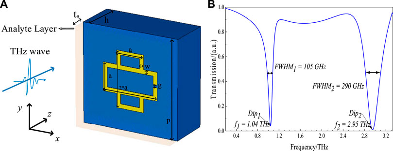
FIGURE 1. (A) Schematic diagram of the proposed THz MM sensor; (B) simulated transmission spectrum of the proposed THz MM.
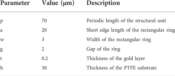
TABLE 1. Geometrical dimensions of the CRSRR structure.
The electromagnetic responses of the designed THz MM structure are evaluated via the finite integration technique (FIT) method using CST Studio Suite 2020 commercial software [18]. The boundary conditions for X/Y and Z directions are set to unit cell and open boundary, respectively. The terahertz transverse electromagnetic (TE) waves vertically incident on the surface of the metamaterial from the metal side, propagating in Z direction with a horizontally polarized E-field (Ex) and a vertically polarized H-field (Hy). Finally, the frequency-domain solver is used to analyze the simulation results and obtain the terahertz transmission spectrum of the metamaterial. Meanwhile, the field monitors need to be activated to collect E-field, H-field, and surface currents at different resonant frequencies.
The physical mechanisms of the resonant modes, the resonance characteristic of the terahertz transmission spectra with different geometrical dimensions of CRSRR, and the sensing performances of the optimized THz MM sensor are discussed in the following section.
3 Results and discussion
3.1 Resonant mechanism of the metamaterial
Figure 1B shows the simulated transmission spectrum of the proposed dual-band THz MM structure. It has two separate transmission dips, which correspond to two resonances, namely low-frequency resonant mode at 1.04 THz (f1) and high-frequency resonant mode at 2.95 THz (f2).
To elucidate the physical mechanisms of both resonant modes, the surface electric fields of the MM structure are collected at both frequencies of the resonant dips. Figures 2A,B depict the electric field distributions of the CRSRR at f1 and f2, respectively. In the resonant mode of f1, the enhanced electric field is located at the gap edge, behaving as a capacitance in an inductance-capacitance (LC) resonant circuit. Such resonance is related to the circular transient current induced by the incident THz field and it can be explained by the LC model [19, 20]. In the other resonance mode of f2, the induced charges are concentrated at the gap on the horizontal rectangular ring and the two vertices on the left of the vertical rectangular ring, forming strong electric fields. It shows that the dipole is excited on the surface of the CRSRR, and this kind of resonance is caused by the dipoles [21]. As a result, the two resonant modes can be recognized as corresponding to LC resonance and dipole resonance, respectively.
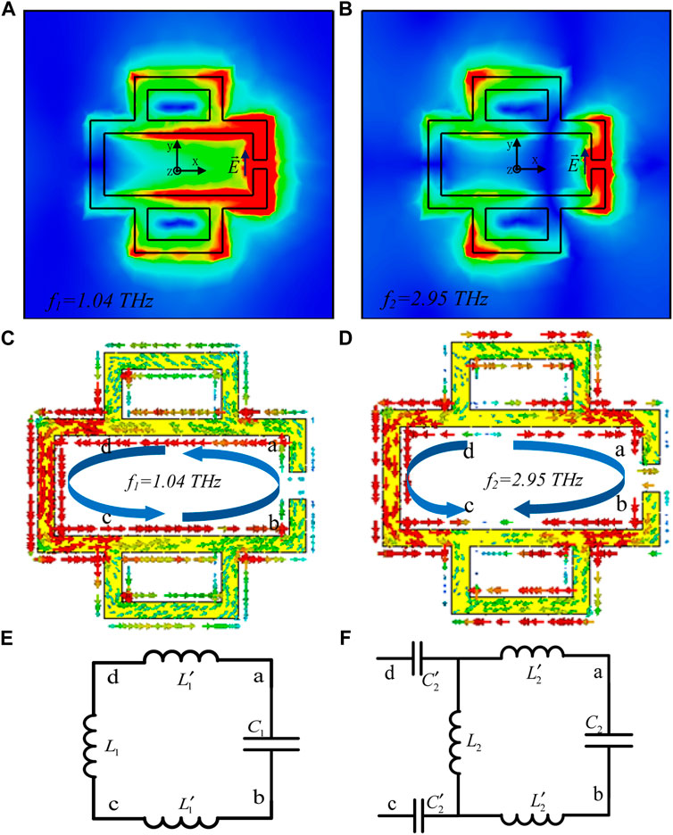
FIGURE 2. E-field distributions of the designed CRSRR at (A) f1 = 1.04 THz, (B) f2 = 2.95 THz; Surface current distributions of the designed CRSRR at (C) f1 = 1.04 THz and (D) f2 = 2.95 THz; Equivalent circuit models at (E) f1 = 1.04 THz and (F) f2 = 2.95 THz.
To further explain the underlying physical mechanisms, the surface currents corresponding to the resonant modes are also studied. Figure 2C exhibits the surface current distribution of the CRSRR at f1, the current directions are consistent in the whole structure, forming a current loop, which indicates that it is an LC resonance. Thus the equivalent circuit can be described as shown in Figure 2E. By neglecting the resistance generated by the inductance, the equivalent impedance of the circuit can be approximately expressed as follows:
Figure 2D exhibits the surface current distribution throughout the CRSRR at the high-frequency resonant mode f2. Unlike the current loop in LC resonance, the direction of current on the left side of the structure is symmetrical to that on the right, which means the charges flow from any direction of point d to point c. Both surface currents parallel to the exciting electric field, which is similar to the electric dipole resonance [22]. The equivalent circuit based on this current distribution is depicted in Figure 2F, in which the impedance can be approximately expressed as follows [13]:
where, ω present angular frequency. The resonance occurs when the imaginary part of the impedance is zero. Hence, both resonant frequencies f1 and f2 of the CRSRR can be calculated according to the resonance formula as
3.2 Influence of geometrical parameters on resonance characteristic
In order to obtain further insight into the resonances characteristic of the proposed MM, several geometrical parameters of the CRSRR structure are altered. By increasing the short edge length a of the rectangular ring from 16 to 24 µm without changing the other geometric parameters (w = 3 μm, g = 2 µm), the resonant frequencies f1 and f2 have varied as shown in Figure 3A. The increase in the value of a makes the equivalent inductance L larger [25]. Considering the influence of L, both resonant frequencies in two modes exhibited the red-shift with the increase of a. Figure 3B shows the transmittance for different a, and the color bar shows the magnitude of transmission intensity. The positions of the resonant frequencies are indicated with the black trace, showing that the distance of the two resonances is decreased due to the a increment. The resonant frequencies and modulation depths under different a are displayed in Figure 3C. The frequency f1 shifts from 1.36 to 0.85 THz while f2 shifts from 3.29 to 2.50 THz when a raises from 16 to 24 µm. Meanwhile, the modulation depths of the dip in the low-frequency resonant mode increased to 97.9 % from 91.2 %, while it increased from 98.6 % to 99.2 % in the high-frequency resonant mode.
FIGURE 3. (A) The transmission spectra of the proposed MM with varying a of CRSRR from 16 to 24 μm (the changing step is 2 μm); (B) Contour plot of numerically simulated transmittance for different a; (C) The relations between resonant frequencies (modulation depths) and the value of a.
On the other side, the width of the proposed CRSRR structure has also been discussed. Figure 4A depicts the transmission spectra with different values of w. The width is inversely proportional to the equivalent inductance L, which meant that the inductance decreased with increasing width w [26]. Therefore, the resonant frequencies f1 and f2 were proportional to the ring width. As the value of w increases from 1 to 4 µm (at keeping a = 20 μm, g = 2 µm), the resonant frequencies increases, that is, the positions of the dips have blue-shifts, which agrees well with the results depicted in Figure 4B. Figure 4C shows the relations between resonance characteristics and the value of w. The frequency f1 moves from 0.95 to 1.09 THz while f2 moves from 2.77 to 3.03 THz with an increasing value of w. Meanwhile, the modulation depth of resonance dips also increased, increasing from 90.7 % to 96.5 % and from 95.7 % to 99.4 % in lower and higher frequency resonant modes, respectively.
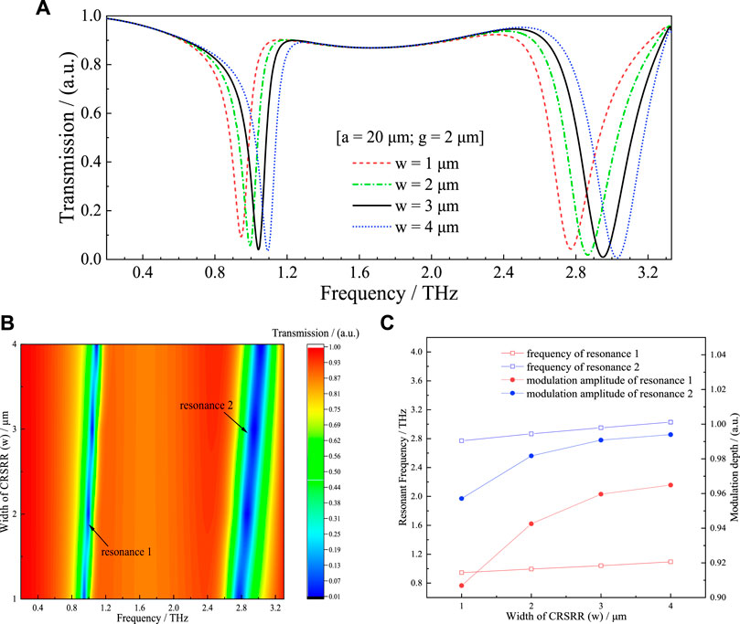
FIGURE 4. (A) The transmission spectra of the proposed MM with varying w from 1 to 4 μm (the changing step is 1 μm); (B) Contour plot of numerically simulated transmittance for different w; (C) The relations between resonant frequencies (modulation depths) and the value of w.
To further investigate the variation trend of the resonant characteristics of the designed CRSRR, the gap distance g is set at values from 1 to 5 µm while keeping the other geometric parameters unchanged (a = 20 μm, w = 3 µm). Figure 5A displays the transmission spectra with the variation of g. For the split-ring structure, the equivalent capacitance almost entirely comes from the charge accumulation at the gap. The larger the gap, the smaller the capacitance, and the resonant frequencies would be higher. Figure 5B shows the blue shifts in both frequencies as predicted. Unlike the effect of parameters a and w, the offsets induced by increasing g are minor. As shown in Figure 5C, the resonance frequency changes from 1.02 to 1.09 THz for f1 and from 2.89 to 3.04 THz for f2 with the variation of g. Also, the modulation depth of the transmission increases from 95.2 % to 96.7 % in the low-frequency resonant mode but reduces from 99.1 % to 98.9 % in the high-frequency resonant mode.
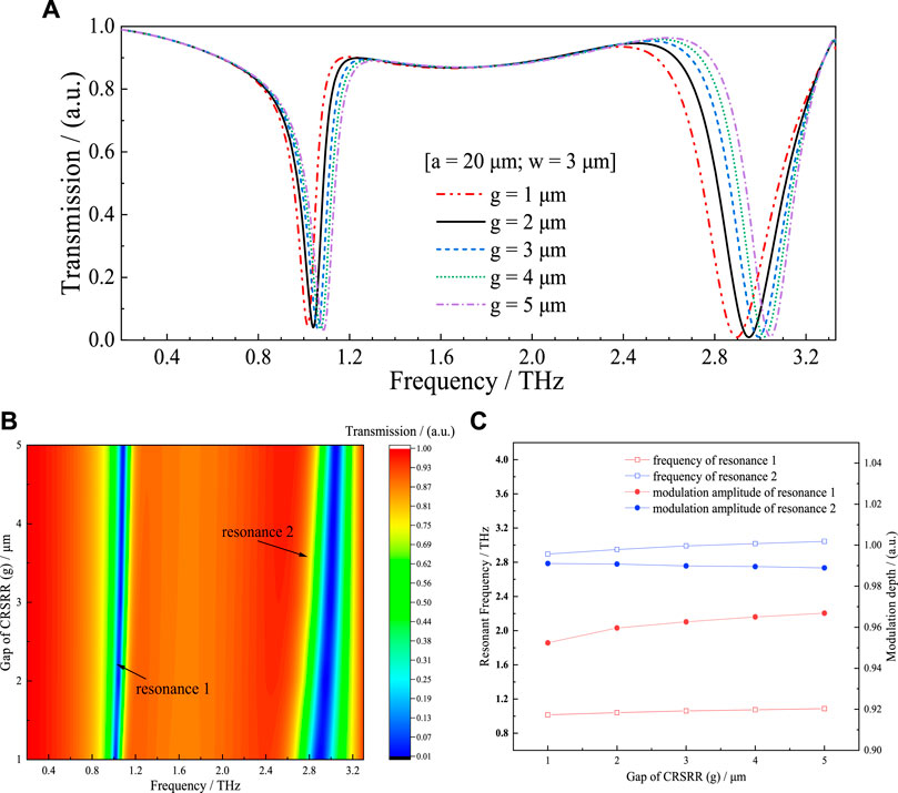
FIGURE 5. (A) The transmission spectra of the proposed MM with varying g from 1 to 5 μm (the changing step is 1 μm); (B) Contour plot of numerically simulated transmittance for different g; (C) The relations between resonant frequencies (modulation depths) and the value of g.
In summary, the metal layout and the gap distance affect the resonance characteristics of the proposed MM. Therefore, the THz MM sensor can be designed with desired resonant frequencies by simply designing the geometric parameters of the CRSRR structure. We proposed a dual-band sensor with initial resonant frequencies at 1.04 and 2.95 THz, in which the geometrical dimensions are of a = 20 μm, w = 3 µm and g = 2 µm. It can be used for detecting trace substance which has characteristic absorption peaks in the range of 0.2–3 THz.
3.3 Sensing performance of the terahertz dual-band sensor
The sensing principle of the THz MM is that, the changes in the surrounding permittivity caused by the analytes with different refractive indices will induce the variation of resonant frequencies in the relevant transmission spectrum [27]. Usually, refractive index sensitivity (S), figure of merit (FOM), and Q-factor are the three critical parameters for assessing the sensing performance of a sensor [28, 29]. Here, the RI sensitivity is defined as:
where Δf is the frequency shift induced by the addition of the analyte layer and Δn is the change of RI. In order to compare the sensing characteristics in different frequency regions, the parameter FOM can be introduced as follows:
where FWHM is the full width at a half-maximum of the resonant. In turn, the Q-factor represents the sharpness of the resonant, and the higher the Q-factor, the better the sensing performance. Here, the Q-factor can be calculated based on the formula below [29]:
In practice, the influence of the analytes on the permittivity of the surrounding environment needs to be considered. In this case, the equivalent capacitance of the designed dual-band metamaterial sensor is approximately equal to the sum of the capacitance of the metamaterial (Cres) and the capacitance caused by in addition of the analyte layer (Canalyte) [30]. The Canalyte increases with the ambient permittivity, which in turn rises with the refractive index of the analyte increment. Therefore, the resonant frequency of the sensor would decrease due to the increasing permittivity, which can be described as follows:
Since the permittivity ɛ is proportional to the refractive index (n) as ɛ = n2 [31], the sensing performance of the proposed THz MM sensor is investigated by changing n of the analyte layer from 1.0 to 1.3 with a changing step of 0.05. The analyte thickness should be in the range where the THz waves and MM can react strongly. Therefore, An analyte layer with a fixed thickness of ta = 10 μm is placed on top of the MM sensor for numerical analysis.
Figure 6A shows the transmission spectra for analytes with different refractive indices. Both resonances are red-shifted with increasing RI. Moreover, the distance of the red-shift in the high-frequency resonant mode is more obvious than that in the low-frequency resonant mode. Figure 6B depicts the offset of the resonant frequency as a function of RI for both resonant modes. With the increase of RI, the positions of resonant dips shift in an approximately linear manner. In turn, the slopes of the fitting curves represented the RI sensitivity of the sensor at the current resonant frequency, which are 309 GHz/RIU for the f1 and 730 GHz/RIU for f2, respectively.
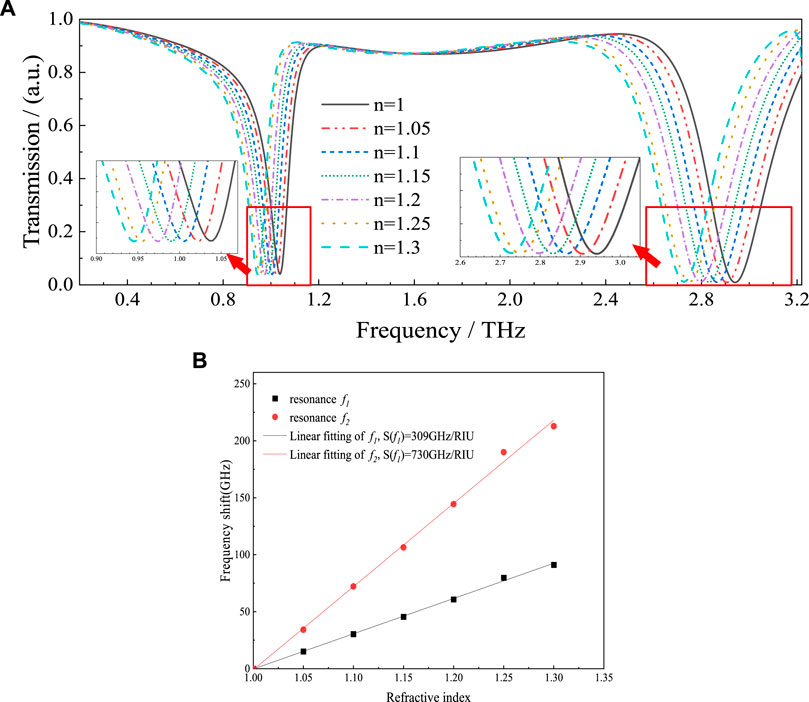
FIGURE 6. (A) The transmission spectra of the proposed sensor with the changes of the RI of analytes; (B) Resonant frequency shift of the sensor as a function of refractive index and the linear fitting results.
To demonstrate the great sensing potential of the proposed dual-band THz MM sensor, the effect of tiny changes of RI on the resonant frequency is afterward numerically evaluated by increasing n of the analyte layer in a range [1.16, 1.2] with a changing step of 0.01. As shown in Figure 7, the spectral dips are red-shifted 13.3 GHz in resonant mode 1 and 21 GHz in resonant mode 2 when the value of n increased by 0.04, which means both resonances are still exhibiting visible frequency changes with the tiny increase of RI. It allows one to distinguish substances in the case of slight differences detected, that is, small changes in the dielectric constant caused by the presence of trace substances can be measured. Therefore, the proposed sensor based on the CRSRR structure meets the high-sensitivity requirements for sensing applications.
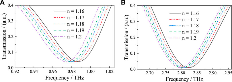
FIGURE 7. The frequency shift of the transmission spectra with RI changed from 1.16 to 1.2 (the changing step is 0.01) in the resonant mode (A) f1 and (B) f2.
In order to obtain a quantitative description of the sensing performance, the RI sensitivity, FOM, and Q-factor of the designed sensor are calculated according to Eqs. 3–5. It is found that S(f1) = 309 GHz/RIU, FOM(f1) = 2.97 (RIU−1), and Q-factor(f1) = 9.96 for the low-frequency resonant mode, while S(f2) = 730 GHz/RIU, FOM(f2) = 2.52 (RIU−1), and Q-factor(f2) = 10.17 for the high-frequency resonant mode. Comparing these results with those most recently reported in the literature [13, 23, 24, 26, 27, 32, 33] (see Table 2), it could be concluded that the proposed dual-band THz MM sensor provides the highest sensitivity among the other analogous appliances. In addition, it enabled one to characterize identical samples at multi frequencies due to its two resonance modes, thereby increasing the selectivity and sensitivity of detection.
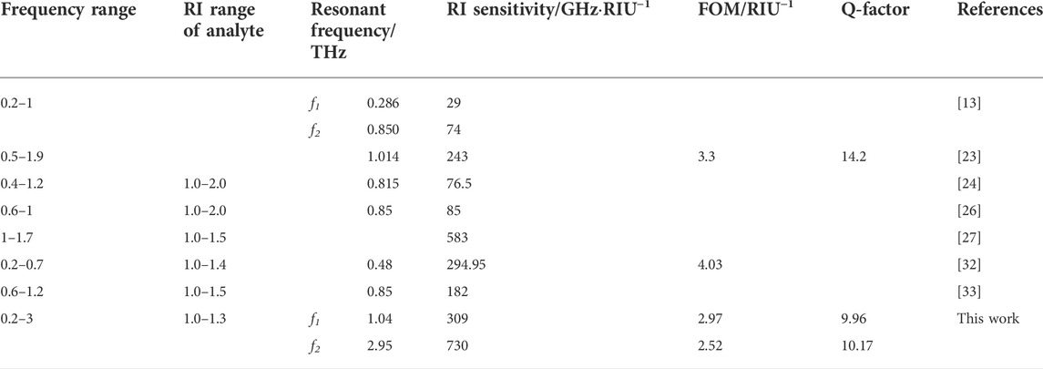
TABLE 2. Comparison of the sensing performance of the proposed sensor with previously reported analogues.
4 Conclusion
In this paper, we propose a THz MM with CRSRR structure and investigate the tuning behavior of unit geometry on resonance characteristics. It is able to design a multi-band sensor with customized resonant frequencies and the interval of resonances by different geometrical parameters of the CRSRR unit. The proposed sensor exhibits a perfect modulation depth of 95.89% at 1.04 THz and 99.06% at 2.95 THz. The sensing performance shows that it has promising prospects for sensing applications, with the theoretical RI sensitivity of 309 GHz/RIU and Q-factor of 9.96 in the low-frequency resonant mode; and the RI sensitivity of 730 GHz/RIU and Q-factor of 10.17 in the high-frequency resonant mode. Meanwhile, as compared to the most traditional sensors with a single resonance, the proposed sensor enables one to realize the multi-channel detection of the analytes, showing more accurate identification results. This work contributes to designing a multi-band THz MM sensor for high sensitivity sensing, which is of great significance for the development of state-of-the-art trace substance detection in future.
Data availability statement
The raw data supporting the conclusions of this article will be made available by the authors, without undue reservation.
Author contributions
Conceptualization, XL; methodology, XL; validation, XL and HG; formal analysis, XL; investigation, XL; writing—original draft preparation, XL; writing—review and editing, HG and YJ; supervision, YZ; funding acquisition, HG and YJ All authors have read and agreed to the published version of the manuscript.
Funding
This research was funded by the National Natural Science Foundation of China (61975053,61705061); Natural Science Foundation of Henan (222300420040, 202300410111); Program for Science & Technology Innovation Talents in Universities of Henan Province (22HASTIT017); Open Fund Project of Key Laboratory of Grain Information Processing & Control, Ministry of Education, Henan University of Technology (KFJJ2020103); Major public welfare projects of Henan Province (201300210100); Innovative Funds Plan of Henan University of Technology (2021ZKCJ04); Cultivation Programme for Young Backbone Teachers in Henan University of Technology; Key Science and Technology Program of Henan Province of China (222102110246); major science and technology project of Henan Province (211110110500).
Conflict of interest
The authors declare that the research was conducted in the absence of any commercial or financial relationships that could be construed as a potential conflict of interest.
Publisher’s note
All claims expressed in this article are solely those of the authors and do not necessarily represent those of their affiliated organizations, or those of the publisher, the editors and the reviewers. Any product that may be evaluated in this article, or claim that may be made by its manufacturer, is not guaranteed or endorsed by the publisher.
References
1. Pickwell E, Wallace VP. Biomedical applications of terahertz technology. J Phys D Appl Phys (2006) 39(17):R301–10. doi:10.1088/0022-3727/39/17/r01
2. Wang K, Sun DW, Pu H. Emerging non-destructive terahertz spectroscopic imaging technique: Principle and applications in the agri-food industry. Trends Food Sci Techn (2017) 67:93–105. doi:10.1016/j.tifs.2017.06.001
3. Yang X, Yang K, Luo Y, Fu W. Terahertz spectroscopy for bacterial detection: Opportunities and challenges. Appl Microbiol Biotechnol (2016) 100(12):5289–99. doi:10.1007/s00253-016-7569-6
4. Tao YH, Fitzgerald AJ, Wallace VP. Non-contact, non-destructive testing in various industrial sectors with terahertz technology. Sensors (2020) 20(3):712. doi:10.3390/s20030712
5. Bernier M, Garet F, Kato E, Blampey B, Coutaz JL. Comparative study of material parameter extraction using terahertz time-domain spectroscopy in transmission and in reflection. J Infrared Millim Terahertz Waves (2018) 39(4):349–66. doi:10.1007/s10762-018-0463-9
6. Beruete M, Jáuregui‐López I. Terahertz sensing based on metasurfaces. Adv Opt Mater (2020) 8(3):1900721. doi:10.1002/adom.201900721
7. Fu X, Liu Y, Chen Q, Fu Y, Cui TJ. Applications of terahertz spectroscopy in the detection and recognition of substances[J]. Front Phys (2022) 427.
8. Jin B, Tan W, Zhang C, Wu J, Chen J, Zhang S, et al. Terahertz sensing: High-performance terahertz sensing at exceptional points in a bilayer structure (adv. Theory simul. 9/2018). Adv Theor Simul (2018) 1(9):1870024. doi:10.1002/adts.201870024
9. Karmakar S, Kumar D, Varshney RK, Chowdhury DR. Strong terahertz matter interaction induced ultrasensitive sensing in Fano cavity based stacked metamaterials. J Phys D Appl Phys (2020) 53(41):415101. doi:10.1088/1361-6463/ab94e3
10. Yen TJ, Padilla WJ, Fang N, Vier DC, Smith DR, Pendry JB, et al. Terahertz magnetic response from artificial materials. Science (2004) 303(5663):1494–6. doi:10.1126/science.1094025
11. Saadeldin AS, Hameed MFO, Elkaramany EMA, Obayya SSA. Highly sensitive terahertz metamaterial sensor. IEEE Sens J (2019) 19(18):7993–9. doi:10.1109/jsen.2019.2918214
12. Zhang J, Mu N, Liu L, Xie J, Feng H, Yao J, et al. Highly sensitive detection of malignant glioma cells using metamaterial-inspired THz biosensor based on electromagnetically induced transparency. Biosens Bioelectron (2021) 185:113241. doi:10.1016/j.bios.2021.113241
13. Li D, Hu F, Zhang H, Chen Z, Huang G, Tang F, et al. Identification of early-stage cervical cancer tissue using metamaterial terahertz biosensor with two resonant absorption frequencies. IEEE J Sel Top Quan Electron (2021) 27(4):1–7. doi:10.1109/jstqe.2021.3058163
14. Islam M, Rao S, Kumar G, Pal BP, Roy Chowdhury D. Role of resonance modes on terahertz metamaterials based thin film sensors. Sci Rep (2017) 7(1):7355–8. doi:10.1038/s41598-017-07720-9
15. O’Hara JF, Singh R, Brener I, Smirnova E, Han J, Taylor AJ, et al. Thin-film sensing with planar terahertz metamaterials: Sensitivity and limitations. Opt Express (2008) 16(3):1786–95. doi:10.1364/oe.16.001786
16. Weis P, Garcia-Pomar JL, Beigang R, Rahm M. Hybridization Induced Transparency in composites of metamaterials and atomic media. Opt Express (2011) 19(23):23573–80. doi:10.1364/oe.19.023573
17. Yu Y, Lin YS. Multi-functional terahertz metamaterial using symmetrical and asymmetrical electric split-ring resonator. Results Phys (2019) 13:102321. doi:10.1016/j.rinp.2019.102321
18. Veeraselvam A, Mohammed GNA, Savarimuthu K, Sankararajan R. A novel multi-band biomedical sensor for THz regime[J]. Opt Quan Electron (2021) 53(7):1–20.
19. Tan C, Liu J, Tian X, Zhu J, Zhang K. Multifunctional and dynamically tunable terahertz metamaterials based on TiNi shape memory alloy films with a simple design. Results Phys (2021) 24:104165. doi:10.1016/j.rinp.2021.104165
20. Pang HZ, Wang X, Wang JL, Wang ZL, Liu SY, Tian HQ. Sensing characteristics of dual band terahertz metamaterial absorber sensor[J]. ACTA PHYSICA SINICA (2021) 70(16).
21. He X, Yang X, Li S, Shi S, Wu F, Jiang J. Electrically active manipulation of electromagnetic induced transparency in hybrid terahertz metamaterial. Opt Mater Express (2016) 6(10):3075–85. doi:10.1364/ome.6.003075
22. Wilbert DS, Hokmabadi MP, Kung P, Kim SM. Equivalent-circuit interpretation of the polarization insensitive performance of THz metamaterial absorbers. IEEE Trans Terahertz Sci Technol (2013) 3(6):846–50. doi:10.1109/tthz.2013.2285311
23. Wang Z, Geng Z, Fang W. Exploring performance of THz metamaterial biosensor based on flexible thin-film. Opt Express (2020) 28(18):26370–84. doi:10.1364/oe.402222
24. Lin S, Xu X, Hu F, Chen Z, Wang Y, Zhang L, et al. Using antibody modified terahertz metamaterial biosensor to detect concentration of carcinoembryonic antigen. IEEE J Sel Top Quan Electron (2020) 27(4):1–7. doi:10.1109/jstqe.2020.3038308
25. Abramovich A, Azoulay Y, Rotshild D. Real-time metasurface sensor for monitoring micropoisons in aqueous solutions based on gold nanoparticles and terahertz spectroscopy. Sensors (2022) 22(3):1279. doi:10.3390/s22031279
26. Li Y, Chen X, Hu F, Li D, Teng H, Rong Q, et al. Four resonators based high sensitive terahertz metamaterial biosensor used for measuring concentration of protein. J Phys D Appl Phys (2019) 52(9):095105. doi:10.1088/1361-6463/aaf7e9
27. Forouzeshfard MR, Ghafari S, Vafapour Z. Solute concentration sensing in two aqueous solution using an optical metamaterial sensor. J Lumin (2021) 230:117734. doi:10.1016/j.jlumin.2020.117734
28. Zhang Y, Li T, Zeng B, Zhang H, Lv H, Huang X, et al. A graphene based tunable terahertz sensor with double Fano resonances. Nanoscale (2015) 7(29):12682–8. doi:10.1039/c5nr03044g
29. Yan F, Li L, Wang R, Tian H, Liu J, Liu J, et al. Ultrasensitive tunable terahertz sensor with graphene plasmonic grating. J Lightwave Technol (2019) 37(4):1103–12. doi:10.1109/jlt.2018.2886412
30. Nickpay MR, Danaie M, Shahzadi A. Highly sensitive THz refractive index sensor based on folded split-ring metamaterial graphene resonators[J]. Plasmonics (2021) 1–12.
31. Khani S, Danaie M, Rezaei P. Plasmonic all-optical metal–insulator–metal switches based on silver nano-rods, comprehensive theoretical analysis and design guidelines. J Comput Electron (2021) 20(1):442–57. doi:10.1007/s10825-020-01638-8
32. Wang G, Zhu F, Lang T, Liu J, Hong Z, Qin J. All-metal terahertz metamaterial biosensor for protein detection. Nanoscale Res Lett (2021) 16(1):109–10. doi:10.1186/s11671-021-03566-3
Keywords: terahertz, metamaterial, dual-band sensor, high RI sensitivity, sensors
Citation: Lu X, Ge H, Jiang Y and Zhang Y (2022) Design and analysis of a dual-band THz metamaterial sensor with high refractive index sensitivity. Front. Phys. 10:973033. doi: 10.3389/fphy.2022.973033
Received: 19 June 2022; Accepted: 02 August 2022;
Published: 30 August 2022.
Edited by:
Yue Wang, Xi’an University of Technology, ChinaReviewed by:
Dibakar Roy Chowdhury, Mahindra École Centrale College of Engineering, IndiaQingli Zhou, Capital Normal University, China
Copyright © 2022 Lu, Ge, Jiang and Zhang. This is an open-access article distributed under the terms of the Creative Commons Attribution License (CC BY). The use, distribution or reproduction in other forums is permitted, provided the original author(s) and the copyright owner(s) are credited and that the original publication in this journal is cited, in accordance with accepted academic practice. No use, distribution or reproduction is permitted which does not comply with these terms.
*Correspondence: Yuan Zhang, zy_haut@163.com