
Thermochemical Conversion of Biomass for Syngas Production: Current Status and Future Trends


 ,
,  ,
,
Abstract
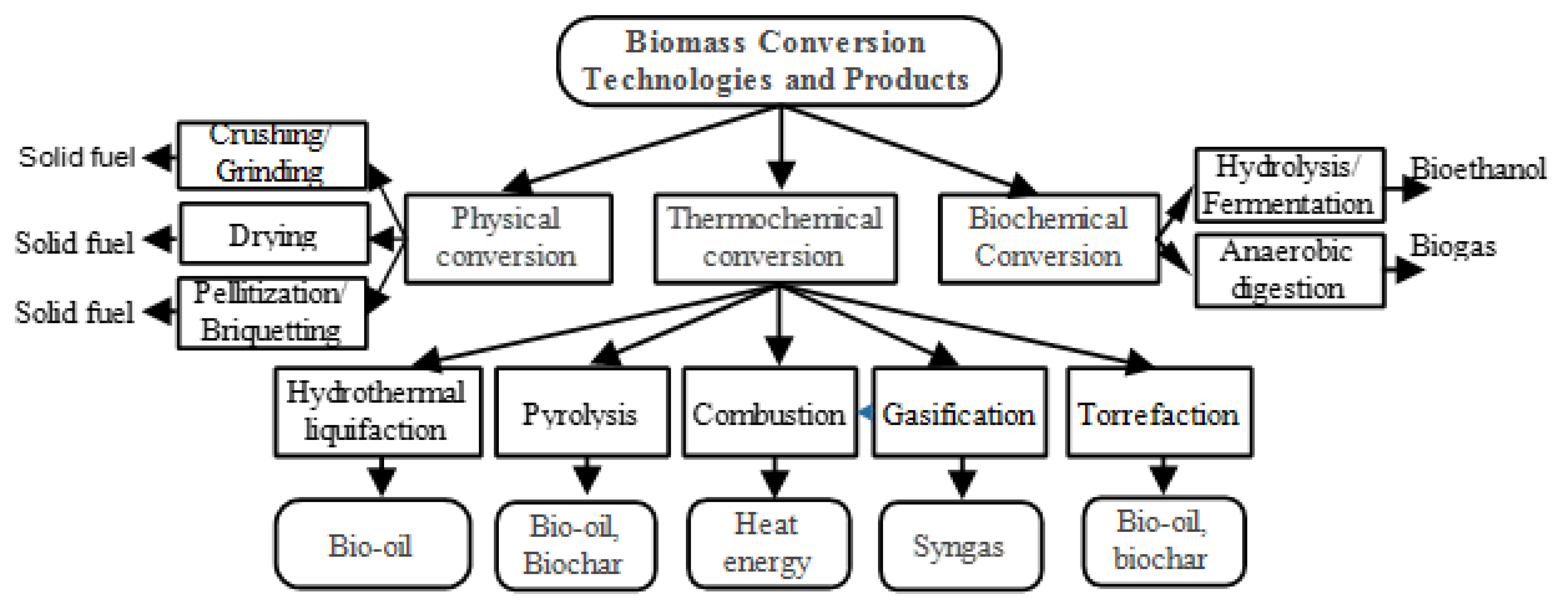
:1. Introduction
1.1. Gasification History and Reactions
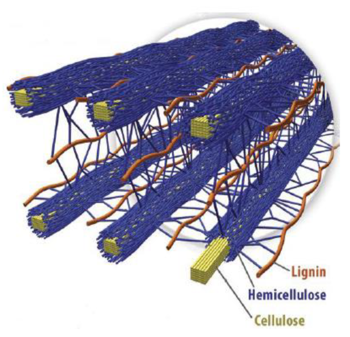
1.2. Characteristics of Lignocellulosic Biomass
2. Effect of Feed Composition on Gasification
2.1. Composition of Feedstock
2.2. Proximate and Ultimate Analysis

| Biomass | Proximate Analysis (%) | Ultimate Analysis (%) | |||||||
|---|---|---|---|---|---|---|---|---|---|
| Moisture | VM | FC | Ash | C | H | S | N | O | |
| SD | 11.98 | 61.36 | 14.36 | 12.30 | 47.33 | 5.41 | 0.32 | 0.79 | 46.15 |
| RH | 7.10 | 65.39 | 8.96 | 18.55 | 34.33 | 5.36 | 0.59 | 0.29 | 59.43 |
| SB | 5.97 | 77.19 | 12.30 | 4.54 | 41.73 | 5.82 | 0.30 | 0.10 | 52.05 |
| CS | 5.58 | 69.98 | 16.31 | 8.13 | 44.10 | 5.96 | 0.19 | 0.36 | 49.39 |
3. Gasification Agents
3.1. Gasifying Agent (Steam)
3.2. Gasifying Agent (Air)
3.3. Gasifying Agent (Oxygen)
4. Catalyst Selection
4.1. Heterogeneous Catalysts
4.2. Homogeneous Catalysts
| Biomass | Conditions | Catalyst | H2 Yields | Methods | Ref |
|---|---|---|---|---|---|
| Wood sawdust | T1 ¼ 535 °C, T2 ¼ 800oC | NiZnAlOx | 48 vol% | Co-precipitation | [72] |
| Wood sawdust | NiO loading: 7.2 wt%; 850 °C | NiO/MgO | 51 vol% | Commercial | [73] |
| Corn stalk | Ni:Mg:Al ¼ 1:1:1; T1 ¼ 400 °C, T2 ¼ 800 °C; S/C ¼ 3.54; 30 min | Ni–Mg–Al | 56% | Co-impregnation | [74] |
| Corncob | Ni loading: 18.0%; 1 h; 650 °C; 1 g biomass; Steam: 30 kPa | Ni/Resin | 61 mmol/g | Ion exchange | [75] |
| Corncob | Ni loading: 17.32%; 1 h; Steam: 30 kPa; 650 °C; 1 g biomass | Ni/lignite | 60 mmol/g | Char Ion exchange | [76] |
| Corncob | Ni loading: 6%; Ar atmosphere; 650 °C; 1 g biomass | Ni/dolomite | 22 mmol/g | Ion exchange | [77] |
| Maize stalk | Ni, Ce loading: 14.9%, 2.0%; 900 °C, S/C ¼ 6; WHSV ¼ 12 h−1 | Ni–Ce/Al2O3 | 71% | Co-impregnation | [78] |
| Pine sawdust | T ¼ 650 °C; GHSV ¼ 13000 h−1; S/C ¼ 7.6; Mg/Al ¼ 0.26; Co/Ni ¼ 0.10 | Ni/Co–Al–Mg | - | Co-precipitation | [79] |
| Pine sawdust | Ni loading: 9.92%; 700 °C; S/C ¼ 12 | Ni/La2O3-αAl2O3 | 96% | Impregnation | [80] |
| Pine wood | S/C ¼ 5.58; 650 °C; Ni loading: 28% | Ni/Al catalysts | 77% | Co-precipitation | [81] |
| Pig manure | Ni loading: 19 ± 1 wt%; 650oC; Ar | Ni/lignite | 69 mmol/g | Char ion exchange | [82] |
| Sawdust | S/C ¼ 5.0; WHSV ¼ 1.5 h−1; 800 °C | Ni/dolomite | 73% | Impregnation | [83] |
| Rice hull | Ni loading: 12%, Ce loading: 7.5%; W/B ¼ 4.9, 800 °C | Ni/CeO2–ZrO2 | 70% | Impregnation | [84] |
| Wood sawdust | Ni loading: 40 wt%, 0.25 g; 800oC; water: 5.0 mL/h | Ni/MCM-41 | 51 vol% | Impregnation | [85] |
| Sawdust | S/CH4 ¼ 2; 800 °C; Catalyst: 15.0 g; GHSV ¼ 3600 h−1 | Ni/MgO | 81% | Commercial | [86] |
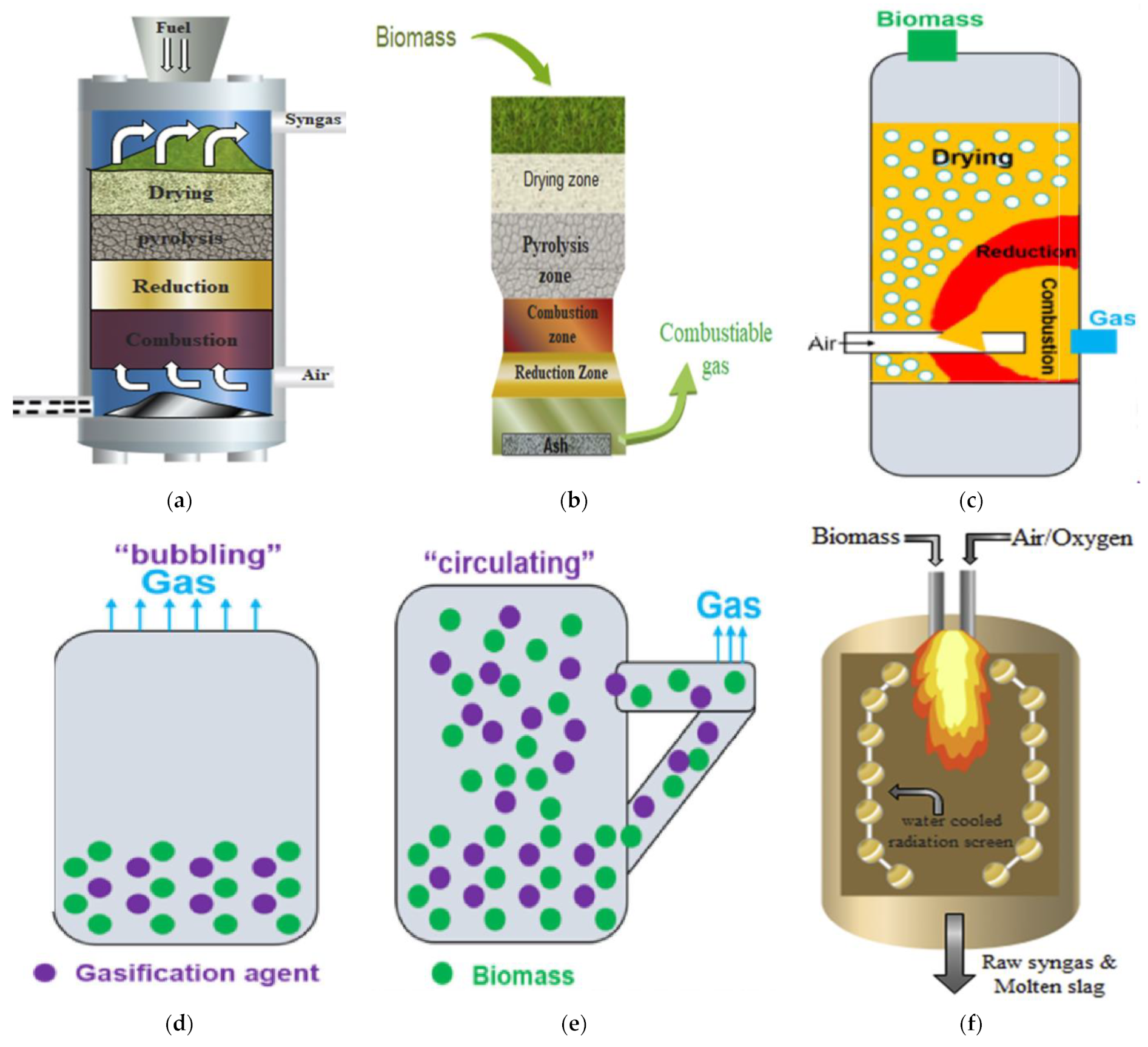
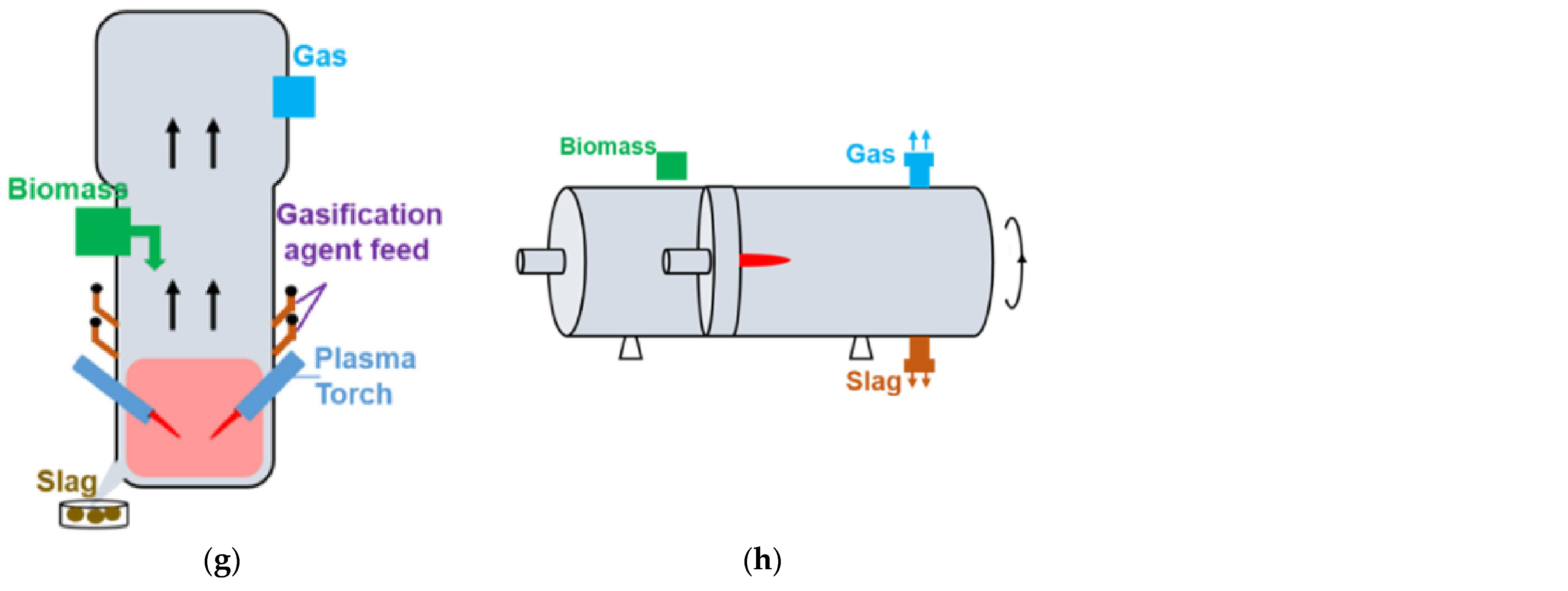
5. Types of Gasifiers
5.1. Fixed-Bed Gasifiers
5.1.1. Updraft Gasifier
5.1.2. Downdraft Gasifier
5.1.3. Cross Draft Gasifier
5.2. Fluidized Bed Gasifiers
5.2.1. Circulating and Bubbling Fluidized Bed Gasifiers
5.2.2. Entrained Flow Reactor
5.2.3. Plasma Reactor
5.2.4. Rotary Kiln
6. Performance of a Gasifier
7. Effect of Operating Parameters on Syngas Composition
7.1. Effect of Temperature
7.2. Effect of Pressure
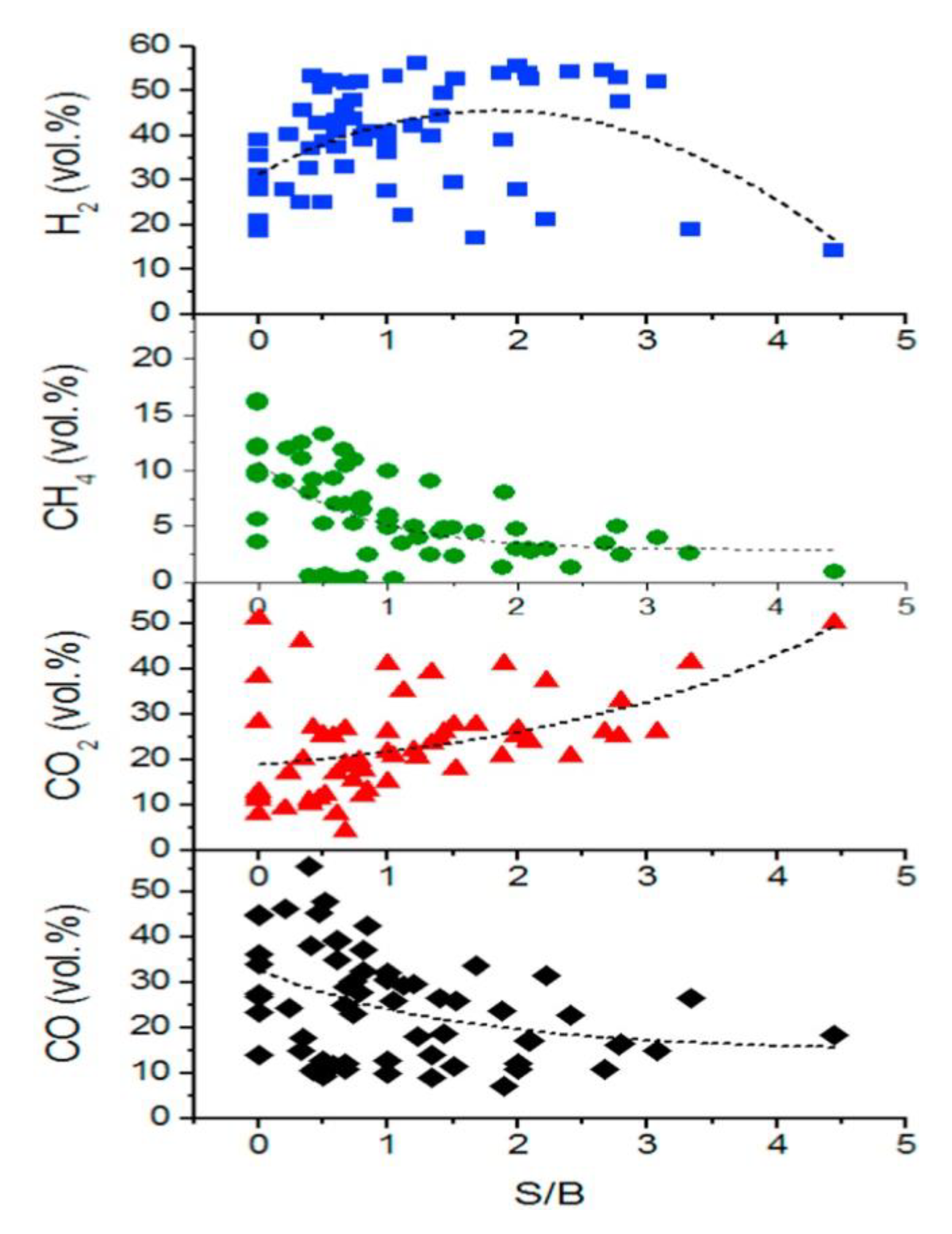
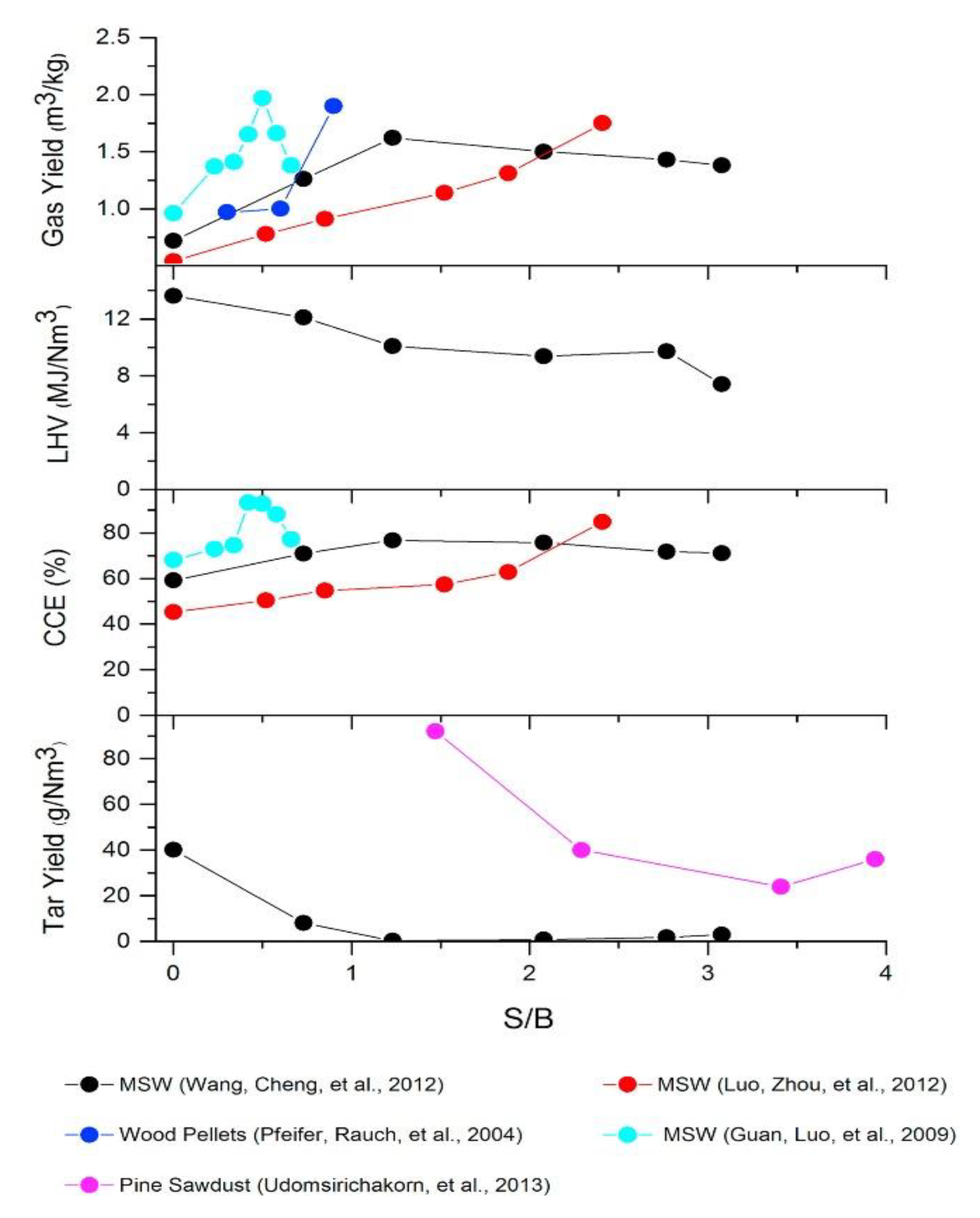
7.3. Effect S/B Ratio
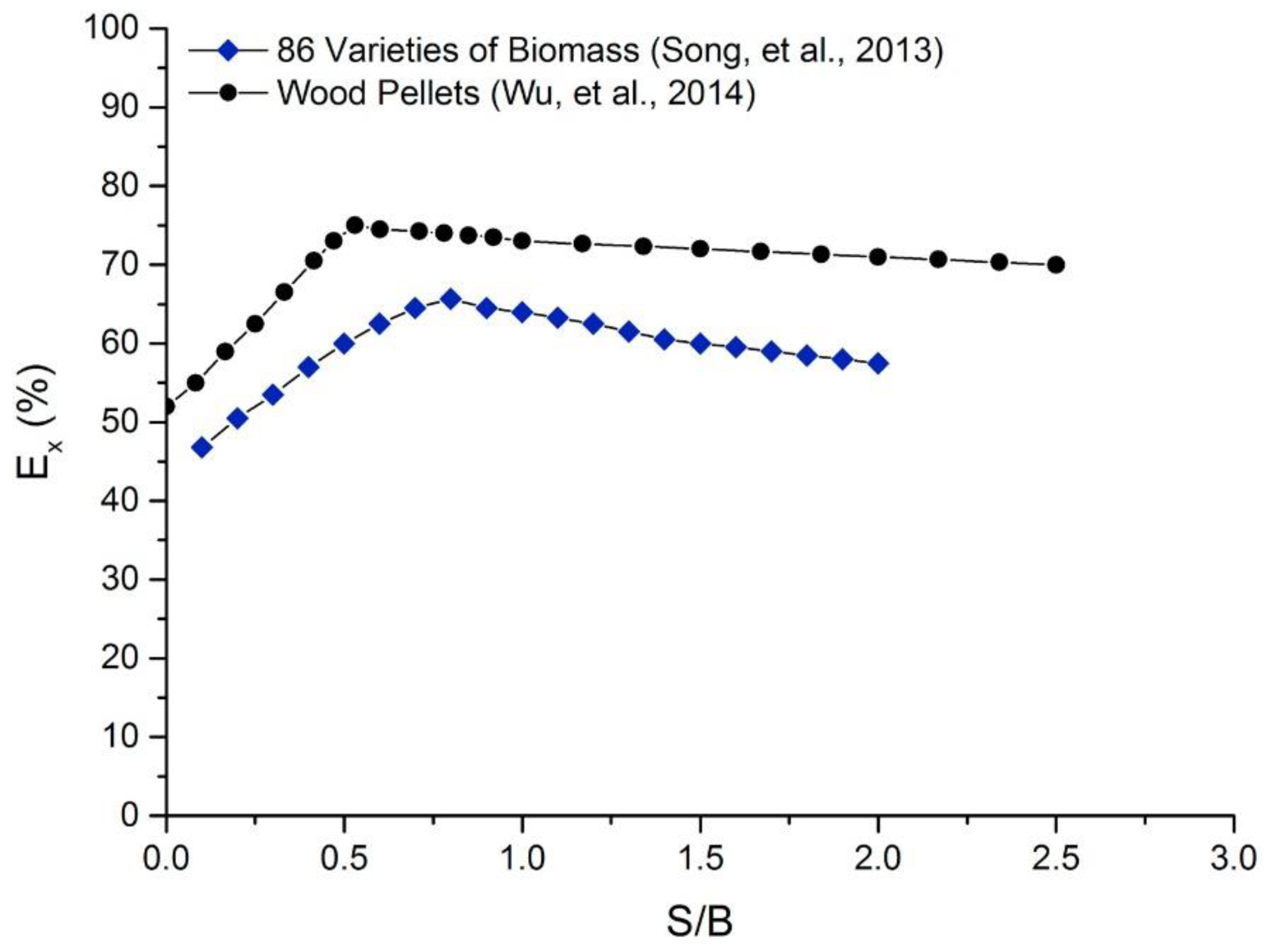
7.4. Energy and Exergy Efficiency
7.5. Formation of Tar and Removal Techniques
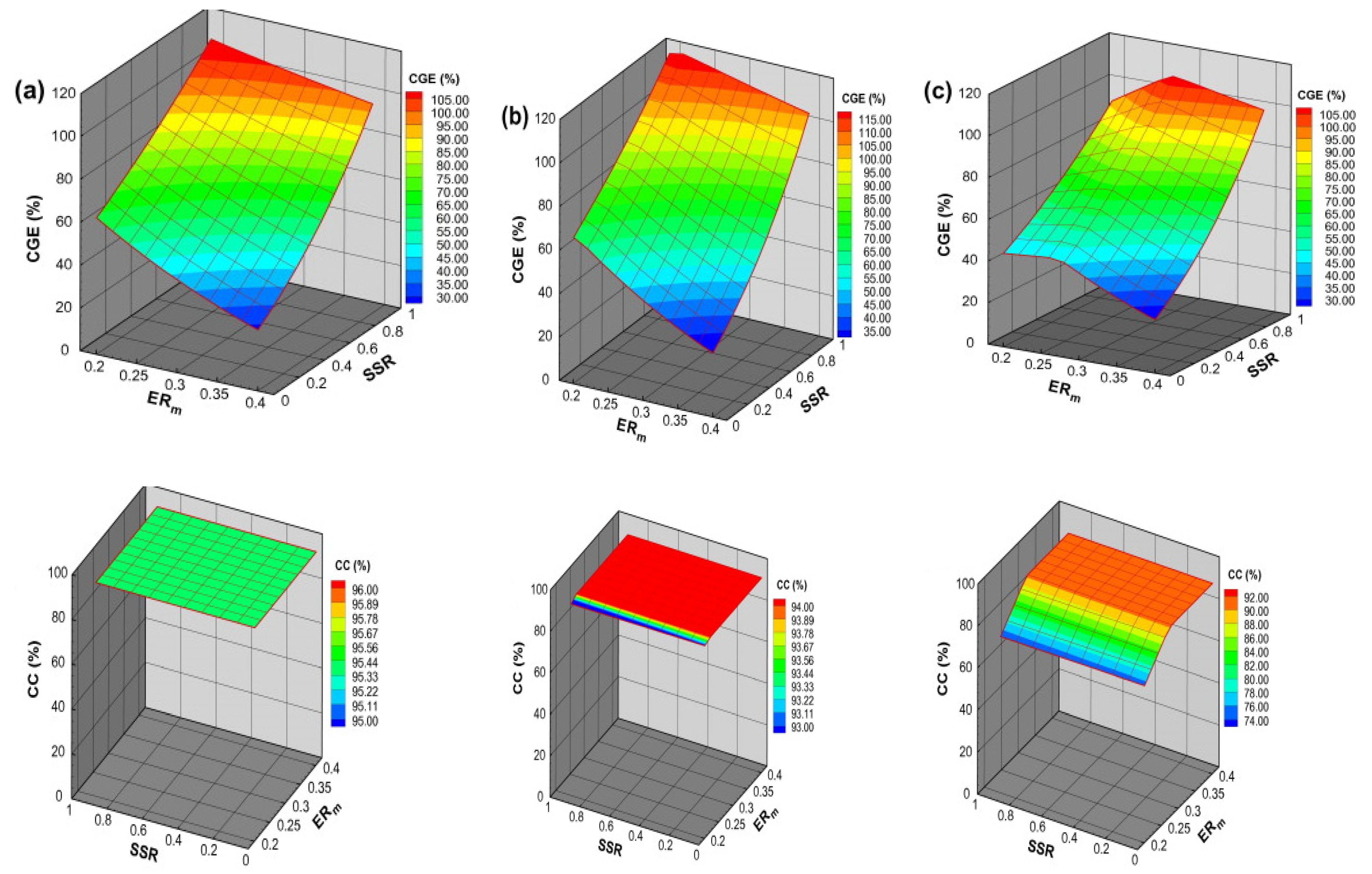
7.6. Carbon Conversion and Cold Gas Efficiency
8. Conclusions
- It is established that an appropriate mixture of pure oxygen with steam has advantages over other options for biomass gasification in terms of technical and economical perspectives;
- The chemical composition of the biomass, reactor design, gasifier temperature, and catalyst work together to selectively separate H2 and improve gasification efficiency;
- The commercial application of biomass gasification is presently restricted to municipal solid waste and agricultural waste;
- The main problems facing the commercial prospects of bio-waste gasification include large amounts of tar in the gas produced, difficulty in separating individual gaseous compounds, and the deactivation of gasification catalysts due to compounds containing nitrogen and sulfur;
- There are several challenges related to plasma gasification, and attention should be paid to the success and future commercialization of plasma gasification;
- The catalytic gasification of biomass is a key technology for environmental and chemical production.
- Develop and demonstrate advanced technologies to transform biomass into fuels and energy;
- Pursue and develop techniques to further incorporate the use of biomass where it is technically viable;
- Develop and optimize sustainable and cost-effective biomass supply;
- Design market-based solutions to foster investments in biomass.
Supplementary Materials
Author Contributions
Funding
Institutional Review Board Statement
Informed Consent Statement
Data Availability Statement
Acknowledgments
Conflicts of Interest
Abbreviations
| H2 | Hydrogen | MW | Megawatt |
| CO | Carbon monoxide | TB | Torrefied bamboo |
| LHV | Lower heating value | SSR | Steam supply ratio |
| oC | Centigrade | S/B | Steam biomass ratio |
| CO2 | Carbon dioxide | ER | Equivalence ratio |
| CH4 | Methane | GE | Gasification efficiency |
| % | Percent | CCE | Carbon conversion efficiency |
| EFG | Entrained flow gasifier | Vol% | Volume percent |
| FBG | Fluidized bed gasifier | HC | Heterogenous catalyst |
| PG | Producer gas | Ni | Nickle |
| MJ/kg | Megajoule per kilogram | NiO | Nickle oxide |
| MJ/L | Megajoule per liter | MgO | Magnesium oxide |
| MJ/m3 | Megajoule per cubic meter | Al2O3 | Aluminum oxide |
| US$/kg | United states dollar per kilogram | CaO | Calcium oxide |
| MSW | Municipal solid waste | NaOH | Sodium hydroxide |
| wt% | Weight percent | KOH | Potassium hydroxide |
| HHV | Higher heating value | SiO2 | Silicon oxide |
| NOx | Nitrogen oxide | BFBG | Bubbling fluidized bed gasifier |
| SOx | Sulfur oxide | CGE | Cold gas efficiency |
| N2 | Nitrogen | SS | Sewage sludge |
| H2S | Hydrogen sulfide | MPa | Megapascal |
| MJ/kmol | Megajoule per kilomole | SOFC | Solid oxide fuel cell |
| WGSR | Water gas shift reaction | CFBG | Circulating fluidized bed gasifier |
| DD | Downdraft | UD | Updraft |
References
- Furlan, F.F.; Filho, R.T.; Pinto, F.H.P.B.; Costa, C.B.B.; Cruz, A.J.G.; Giordano, R.L.C.; Giordano, R.C. Bioelectricity versus bioethanol from sugarcane bagasse: Is it worth being flexible? Biotechnol. Biofuels 2013, 6, 142. [Google Scholar] [CrossRef] [PubMed] [Green Version]
- Dantas, G.A.; Legey, L.F.L.; Mazzone, A. Energy from sugarcane bagasse in Brazil: An assessment of the productivity and cost of different technological routes. Renew. Sustain. Energy Rev. 2013, 21, 356–364. [Google Scholar] [CrossRef]
- Seabra, J.E.A.; Macedo, I.C. Comparative analysis for power generation and ethanol production from sugarcane residual biomass in Brazil. Energy Policy 2011, 39, 421–428. [Google Scholar] [CrossRef]
- Akay, G.; Jordan, C.A. Gasification of Fuel Cane Bagasse in a Downdraft Gasifier: Influence of Lignocellulosic Composition and Fuel Particle Size on Syngas Composition and Yield. Energy Fuels 2011, 25, 2274–2283. [Google Scholar] [CrossRef]
- Ahmed, I.I.; Gupta, A.K. Sugarcane bagasse gasification: Global reaction mechanism of syngas evolution. Appl. Energy 2012, 91, 75–81. [Google Scholar] [CrossRef]
- IRENA; International Renewable Energy Agency. Renewable Energy Target Setting; International Renewable Energy Agency: Abu Dhabi, United Arab Emirates, 2015. [Google Scholar]
- Demirbas, A. Emission Characteristics of Gasohol and Diesohol. Energy Sources Part A Recovery Util. Environ. Eff. 2009, 31, 1099–1104. [Google Scholar] [CrossRef]
- Foust, T.D.; Aden, A.; Dutta, A.; Phillips, S. An economic and environmental comparison of a biochemical and a thermochemical lignocellulosic ethanol conversion processes. Cellulose 2009, 16, 547–565. [Google Scholar] [CrossRef]
- Demirbas, A. Biofuels sources, biofuel policy, biofuel economy and global biofuel projections. Energy Convers. Manag. 2008, 49, 2106–2116. [Google Scholar] [CrossRef]
- De Filippis, P.; Borgianni, C.; Paolucci, M.; Pochetti, F. Gasification process of Cuban bagasse in a two-stage reactor. Biomass Bioenergy 2004, 27, 247–252. [Google Scholar] [CrossRef]
- Demirbas, A. (Ed.) Thermochemical Conversion Processes. In Biofuels: Securing the Planet’s Future Energy Needs; Springer London: London, UK, 2009; pp. 261–304. [Google Scholar]
- Pinto, F.; André, R.N.; Carolino, C.; Miranda, M. Hot treatment and upgrading of syngas obtained by co-gasification of coal and wastes. Fuel Process. Technol. 2014, 126, 19–29. [Google Scholar] [CrossRef] [Green Version]
- Anukam, A.; Mamphweli, S.; Reddy, P.; Meyer, E.; Okoh, O. Pre-processing of sugarcane bagasse for gasification in a downdraft biomass gasifier system: A comprehensive review. Renew. Sustain. Energy Rev. 2016, 66, 775–801. [Google Scholar] [CrossRef] [Green Version]
- Mohanty, P.; Pant, K.K.; Naik, S.N.; Parikh, J.; Hornung, A.; Sahu, J.N. Synthesis of green fuels from biogenic waste through thermochemical route—The role of heterogeneous catalyst: A review. Renew. Sustain. Energy Rev. 2014, 38, 131–153. [Google Scholar] [CrossRef]
- Samiran, N.A.; Jaafar, M.N.M.; Ng, J.-H.; Lam, S.S.; Chong, C.T. Progress in biomass gasification technique—With focus on Malaysian palm biomass for syngas production. Renew. Sustain. Energy Rev. 2016, 62, 1047–1062. [Google Scholar] [CrossRef]
- Bocci, E.; Sisinni, M.; Moneti, M.; Vecchione, L.; Di Carlo, A.; Villarini, M. State of Art of Small Scale Biomass Gasification Power Systems: A Review of the Different Typologies. Energy Procedia 2014, 45, 247–256. [Google Scholar] [CrossRef] [Green Version]
- Sansaniwal, S.K.; Pal, K.; Rosen, M.A.; Tyagi, S.K. Recent advances in the development of biomass gasification technology: A comprehensive review. Renew. Sustain. Energy Rev. 2017, 72, 363–384. [Google Scholar] [CrossRef]
- Ahrenfeldt, J.; Thomsen, T.P.; Henriksen, U.; Clausen, L.R. Biomass gasification cogeneration—A review of state of the art technology and near future perspectives. Appl. Therm. Eng. 2013, 50, 1407–1417. [Google Scholar] [CrossRef] [Green Version]
- Puig-Arnavat, M.; Bruno, J.C.; Coronas, A. Modeling of trigeneration configurations based on biomass gasification and comparison of performance. Appl. Energy 2014, 114, 845–856. [Google Scholar] [CrossRef]
- Puig-Arnavat, M.; Bruno, J.C.; Coronas, A. Review and analysis of biomass gasification models. Renew. Sustain. Energy Rev. 2010, 14, 2841–2851. [Google Scholar] [CrossRef]
- Demirbaş, A. Biomass resource facilities and biomass conversion processing for fuels and chemicals. Energy Convers. Manag. 2001, 42, 1357–1378. [Google Scholar] [CrossRef]
- Kirkels, A.F.; Verbong, G.P.J. Biomass gasification: Still promising? A 30-year global overview. Renew. Sustain. Energy Rev. 2011, 15, 471–481. [Google Scholar] [CrossRef]
- Motta, I.L.; Miranda, N.T.; Maciel Filho, R.; Maciel, M.R.W. Biomass gasification in fluidized beds: A review of biomass moisture content and operating pressure effects. Renew. Sustain. Energy Rev. 2018, 94, 998–1023. [Google Scholar] [CrossRef]
- Ruiz, J.A.; Juárez, M.C.; Morales, M.P.; Muñoz, P.; Mendívil, M.A. Biomass gasification for electricity generation: Review of current technology barriers. Renew. Sustain. Energy Rev. 2013, 18, 174–183. [Google Scholar] [CrossRef]
- Phitsuwan, P.; Sakka, K.; Ratanakhanokchai, K. Improvement of lignocellulosic biomass in planta: A review of feedstocks, biomass recalcitrance, and strategic manipulation of ideal plants designed for ethanol production and processability. Biomass Bioenergy 2013, 58, 390–405. [Google Scholar] [CrossRef]
- Palma, C.F. Modelling of tar formation and evolution for biomass gasification: A review. Appl. Energy 2013, 111, 129–141. [Google Scholar] [CrossRef]
- Devendra, L.P.; Kiran Kumar, M.; Pandey, A. Evaluation of hydrotropic pretreatment on lignocellulosic biomass. Bioresour. Technol. 2016, 213, 350–358. [Google Scholar] [CrossRef] [PubMed]
- Sun, S.; Sun, S.; Cao, X.; Sun, R. The role of pretreatment in improving the enzymatic hydrolysis of lignocellulosic materials. Bioresour. Technol. 2016, 199, 49–58. [Google Scholar] [CrossRef] [PubMed]
- Kalinci, Y.; Hepbasli, A.; Dincer, I. Comparative exergetic performance analysis of hydrogen production from oil palm wastes and some other biomasses. Int. J. Hydrog. Energy 2011, 36, 11399–11407. [Google Scholar] [CrossRef]
- Faba, L.; Díaz, E.; Ordóñez, S. Recent developments on the catalytic technologies for the transformation of biomass into biofuels: A patent survey. Renew. Sustain. Energy Rev. 2015, 51, 273–287. [Google Scholar] [CrossRef]
- He, M.; Xiao, B.; Liu, S.; Guo, X.; Luo, S.; Xu, Z.; Feng, Y.; Hu, Z. Hydrogen-rich gas from catalytic steam gasification of municipal solid waste (MSW): Influence of steam to MSW ratios and weight hourly space velocity on gas production and composition. Int. J. Hydrog. Energy 2009, 34, 2174–2183. [Google Scholar] [CrossRef]
- Wang, J.; Cheng, G.; You, Y.; Xiao, B.; Liu, S.; He, P.; Guo, D.; Guo, X.; Zhang, G. Hydrogen-rich gas production by steam gasification of municipal solid waste (MSW) using NiO supported on modified dolomite. Int. J. Hydrog. Energy 2012, 37, 6503–6510. [Google Scholar] [CrossRef]
- Zhang, Q.; Dor, L.; Zhang, L.; Yang, W.; Blasiak, W. Performance analysis of municipal solid waste gasification with steam in a Plasma Gasification Melting reactor. Appl. Energy 2012, 98, 219–229. [Google Scholar] [CrossRef]
- Roche, E.; de Andrés, J.M.; Narros, A.; Rodríguez, M.E. Air and air-steam gasification of sewage sludge. The influence of dolomite and throughput in tar production and composition. Fuel 2014, 115, 54–61. [Google Scholar] [CrossRef]
- De Andrés, J.M.; Narros, A.; Rodríguez, M.E. Air-steam gasification of sewage sludge in a bubbling bed reactor: Effect of alumina as a primary catalyst. Fuel Process. Technol. 2011, 92, 433–440. [Google Scholar] [CrossRef] [Green Version]
- Gai, C.; Guo, Y.; Liu, T.; Peng, N.; Liu, Z. Hydrogen-Rich gas production by steam gasification of hydrochar derived from sewage sludge. Int. J. Hydrog. Energy 2016, 41, 3363–3372. [Google Scholar] [CrossRef]
- Xiao, X.; Le, D.D.; Li, L.; Meng, X.; Cao, J.; Morishita, K.; Takarada, T. Catalytic steam gasification of biomass in fluidized bed at low temperature: Conversion from livestock manure compost to hydrogen-rich syngas. Biomass Bioenergy 2010, 34, 1505–1512. [Google Scholar] [CrossRef]
- Yong, T.L.-K.; Matsumura, Y. Catalytic Gasification of Poultry Manure and Eucalyptus Wood Mixture in Supercritical Water. Ind. Eng. Chem. Res. 2012, 51, 5685–5690. [Google Scholar] [CrossRef]
- Ro, K.S.; Cantrell, K.; Elliott, D.; Hunt, P.G. Catalytic Wet Gasification of Municipal and Animal Wastes. Ind. Eng. Chem. Res. 2007, 46, 8839–8845. [Google Scholar] [CrossRef]
- Tushar, M.S.H.K.; Dutta, A.; Xu, C. Catalytic supercritical gasification of biocrude from hydrothermal liquefaction of cattle manure. Appl. Catal. B Environ. 2016, 189, 119–132. [Google Scholar] [CrossRef]
- Seif, S.; Tavakoli, O.; Fatemi, S.; Bahmanyar, H. Subcritical water gasification of beet-based distillery wastewater for hydrogen production. J. Supercrit. Fluids 2015, 104, 212–220. [Google Scholar] [CrossRef]
- Cao, C.; Guo, L.; Chen, Y.; Guo, S.; Lu, Y. Hydrogen production from supercritical water gasification of alkaline wheat straw pulping black liquor in continuous flow system. Int. J. Hydrog. Energy 2011, 36, 13528–13535. [Google Scholar] [CrossRef]
- Luo, S.; Xiao, B.; Hu, Z.; Liu, S.; Guo, X.; He, M. Hydrogen-rich gas from catalytic steam gasification of biomass in a fixed bed reactor: Influence of temperature and steam on gasification performance. Int. J. Hydrog. Energy 2009, 34, 2191–2194. [Google Scholar] [CrossRef]
- Wu, W.; Kawamoto, K.; Kuramochi, H. Hydrogen-rich synthesis gas production from waste wood via gasification and reforming technology for fuel cell application. J. Mater Cycles Waste Manag. 2006, 8, 70–77. [Google Scholar] [CrossRef]
- Ge, H.; Guo, W.; Shen, L.; Song, T.; Xiao, J. Experimental investigation on biomass gasification using chemical looping in a batch reactor and a continuous dual reactor. Chem. Eng. J. 2016, 286, 689–700. [Google Scholar] [CrossRef]
- Jin, H.; Lu, Y.; Guo, L.; Zhang, X.; Pei, A. Hydrogen Production by Supercritical Water Gasification of Biomass with Homogeneous and Heterogeneous Catalyst. Adv. Condens. Matter Phys. 2014, 2014, 160565. [Google Scholar] [CrossRef] [Green Version]
- Acelas, N.Y.; López, D.P.; Brilman, D.W.F.; Kersten, S.R.A.; Kootstra, A.M.J. Supercritical water gasification of sewage sludge: Gas production and phosphorus recovery. Bioresour. Technol. 2014, 174, 167–175. [Google Scholar] [CrossRef]
- Sawai, O.; Nunoura, T.; Yamamoto, K. Supercritical water gasification of sewage sludge using bench-scale batch reactor: Advantages and drawbacks. J. Mater Cycles Waste Manag. 2014, 16, 82–92. [Google Scholar] [CrossRef]
- Basu, P. (Ed.) Production of Synthetic Fuels and Chemicals from Biomass. In Biomass Gasification and Pyrolysis; Academic Press: Boston, MA, USA, 2010; Chapter 9; pp. 301–323. [Google Scholar]
- Higman, C.; van der Burgt, M. (Eds.) The Thermodynamics of Gasification. In Gasification; Gulf Professional Publishing: Burlington, VT, USA, 2003; Chapter 2; pp. 9–28. [Google Scholar]
- Maitlo, G.; Unar, I.N.; Mahar, R.B.; Brohi, K.M. Numerical simulation of lignocellulosic biomass gasification in concentric tube entrained flow gasifier through computational fluid dynamics. Energy Exploar. Exploit. 2019, 37, 1073–1097. [Google Scholar] [CrossRef] [Green Version]
- Maitlo, G.; Unar, I.N.; Shah, S.A.K. Thermogravimetric analysis of Pakistani biomasses using nitrogen and oxygen as a carrier gas. Chem. Pap. 2019, 73, 601–609. [Google Scholar] [CrossRef]
- Niu, M.; Huang, Y.; Jin, B.; Wang, X. Oxygen Gasification of Municipal Solid Waste in a Fixed-bed Gasifier. Chin. J. Chem. Eng. 2014, 22, 1021–1026. [Google Scholar] [CrossRef]
- Gil, J.; Corella, J.; Aznar, M.A.P.; Caballero, M.A. Biomass gasification in atmospheric and bubbling fluidized bed: Effect of the type of gasifying agent on the product distribution. Biomass Bioenergy 1999, 17, 389–403. [Google Scholar] [CrossRef]
- García, L.; Salvador, M.L.; Arauzo, J.; Bilbao, R. Catalytic Steam Gasification of Pine Sawdust. Effect of Catalyst Weight/Biomass Flow Rate and Steam/Biomass Ratios on Gas Production and Composition. Energy Fuels 1999, 13, 851–859. [Google Scholar] [CrossRef]
- Hernández, J.J.; Aranda, G.; Barba, J.; Mendoza, J.M. Effect of steam content in the air–steam flow on biomass entrained flow gasification. Fuel Process. Technol. 2012, 99, 43–55. [Google Scholar] [CrossRef]
- Rapagnà, S.; Jand, N.; Kiennemann, A.; Foscolo, P.U. Steam-Gasification of biomass in a fluidised-bed of olivine particles. Biomass Bioenergy 2000, 19, 187–197. [Google Scholar] [CrossRef]
- Li, X.; Li, C.-Z. Volatilisation and catalytic effects of alkali and alkaline earth metallic species during the pyrolysis and gasification of Victorian brown coal. Part VIII. Catalysis and changes in char structure during gasification in steam. Fuel 2006, 85, 1518–1525. [Google Scholar] [CrossRef]
- Lucas, C.; Szewczyk, D.; Blasiak, W.; Mochida, S. High-Temperature air and steam gasification of densified biofuels. Biomass Bioenergy 2004, 27, 563–575. [Google Scholar] [CrossRef]
- Navarro, R.M.; Peña, M.A.; Fierro, J.L.G. Hydrogen Production Reactions from Carbon Feedstocks: Fossil Fuels and Biomass. Chem. Rev. 2007, 107, 3952–3991. [Google Scholar] [CrossRef] [PubMed]
- Hamelinck, C.N.; Faaij, A.P. Future prospects for production of methanol and hydrogen from biomass. J. Power Sources 2002, 111, 1–22. [Google Scholar] [CrossRef]
- Mohammed, M.A.A.; Salmiaton, A.; Wan Azlina, W.A.K.G.; Mohammad Amran, M.S.; Fakhru’l-Razi, A. Air gasification of empty fruit bunch for hydrogen-rich gas production in a fluidized-bed reactor. Energy Convers. Manag. 2011, 52, 1555–1561. [Google Scholar] [CrossRef]
- Xiao, R.; Jin, B.; Zhou, H.; Zhong, Z.; Zhang, M. Air gasification of polypropylene plastic waste in fluidized bed gasifier. Energy Convers. Manag. 2007, 48, 778–786. [Google Scholar] [CrossRef]
- Hamad, M.A.; Radwan, A.M.; Heggo, D.A.; Moustafa, T. Hydrogen rich gas production from catalytic gasification of biomass. Renew. Energy 2016, 85, 1290–1300. [Google Scholar] [CrossRef]
- Gao, N.; Li, A.; Quan, C.; Qu, Y.; Mao, L. Characteristics of hydrogen-rich gas production of biomass gasification with porous ceramic reforming. Int. J. Hydrog. Energy 2012, 37, 9610–9618. [Google Scholar] [CrossRef]
- Zhao, Y.; Sun, S.; Zhou, H.; Sun, R.; Tian, H.; Luan, J.; Qian, J. Experimental study on sawdust air gasification in an entrained-flow reactor. Fuel Process. Technol. 2010, 91, 910–914. [Google Scholar] [CrossRef]
- Manyà, J.J.; Sánchez, J.L.; Ábrego, J.; Gonzalo, A.; Arauzo, J. Influence of gas residence time and air ratio on the air gasification of dried sewage sludge in a bubbling fluidised bed. Fuel 2006, 85, 2027–2033. [Google Scholar] [CrossRef]
- Mansaray, K.G.; Ghaly, A.E.; Al-Taweel, A.M.; Hamdullahpur, F.; Ugursal, V.I. Air gasification of rice husk in a dual distributor type fluidized bed gasifier. Biomass Bioenergy 1999, 17, 315–332. [Google Scholar] [CrossRef]
- Islam, M.W. A review of dolomite catalyst for biomass gasification tar removal. Fuel 2020, 267, 117095. [Google Scholar] [CrossRef]
- Guan, Y.; Luo, S.; Liu, S.; Xiao, B.; Cai, L. Steam catalytic gasification of municipal solid waste for producing tar-free fuel gas. Int. J. Hydrog. Energy 2009, 34, 9341–9346. [Google Scholar] [CrossRef]
- Hu, M.; Guo, D.; Ma, C.; Hu, Z.; Zhang, B.; Xiao, B.; Luo, S.; Wang, J. Hydrogen-rich gas production by the gasification of wet MSW (municipal solid waste) coupled with carbon dioxide capture. Energy 2015, 90, 857–863. [Google Scholar] [CrossRef]
- Dong, L.; Wu, C.; Ling, H.; Shi, J.; Williams, P.T.; Huang, J. Promoting hydrogen production and minimizing catalyst deactivation from the pyrolysis-catalytic steam reforming of biomass on nanosized NiZnAlOx catalysts. Fuel 2017, 188, 610–620. [Google Scholar] [CrossRef]
- Ma, Z.; Zhang, S.-P.; Xie, D.-Y.; Yan, Y.-J. A novel integrated process for hydrogen production from biomass. Int. J. Hydrog. Energy 2014, 39, 1274–1279. [Google Scholar] [CrossRef]
- Yao, D.; Wu, C.; Yang, H.; Hu, Q.; Nahil, M.A.; Chen, H.; Williams, P.T. Hydrogen production from catalytic reforming of the aqueous fraction of pyrolysis bio-oil with modified Ni–Al catalysts. Int. J. Hydrog. Energy 2014, 39, 14642–14652. [Google Scholar] [CrossRef] [Green Version]
- Cao, J.-P.; Liu, T.-L.; Ren, J.; Zhao, X.-Y.; Wu, Y.; Wang, J.-X.; Ren, X.-Y.; Wei, X.-Y. Preparation and characterization of nickel loaded on resin char as tar reforming catalyst for biomass gasification. J. Anal. Appl. Pyrolysis 2017, 127, 82–90. [Google Scholar] [CrossRef]
- Ren, J.; Cao, J.-P.; Zhao, X.-Y.; Wei, F.; Liu, T.-L.; Fan, X.; Zhao, Y.-P.; Wei, X.-Y. Preparation of high-dispersion Ni/C catalyst using modified lignite as carbon precursor for catalytic reforming of biomass volatiles. Fuel 2017, 202, 345–351. [Google Scholar] [CrossRef]
- Zhao, X.-Y.; Ren, J.; Cao, J.-P.; Wei, F.; Zhu, C.; Fan, X.; Zhao, Y.-P.; Wei, X.-Y. Catalytic Reforming of Volatiles from Biomass Pyrolysis for Hydrogen-Rich Gas Production over Limonite Ore. Energy Fuels 2017, 31, 4054–4060. [Google Scholar] [CrossRef]
- Fu, P.; Yi, W.; Li, Z.; Bai, X.; Zhang, A.; Li, Y.; Li, Z. Investigation on hydrogen production by catalytic steam reforming of maize stalk fast pyrolysis bio-oil. Int. J. Hydrog. Energy 2014, 39, 13962–13971. [Google Scholar] [CrossRef]
- Remón, J.; Broust, F.; Valette, J.; Chhiti, Y.; Alava, I.; Fernandez-Akarregi, A.R.; Arauzo, J.; Garcia, L. Production of a hydrogen-rich gas from fast pyrolysis bio-oils: Comparison between homogeneous and catalytic steam reforming routes. Int. J. Hydrog. Energy 2014, 39, 171–182. [Google Scholar] [CrossRef]
- Remiro, A.; Valle, B.; Aguayo, A.T.; Bilbao, J.; Gayubo, A.G. Operating conditions for attenuating Ni/La2O3–αAl2O3 catalyst deactivation in the steam reforming of bio-oil aqueous fraction. Fuel Process. Technol. 2013, 115, 222–232. [Google Scholar] [CrossRef]
- Bimbela, F.; Oliva, M.; Ruiz, J.; García, L.; Arauzo, J. Hydrogen production via catalytic steam reforming of the aqueous fraction of bio-oil using nickel-based coprecipitated catalysts. Int. J. Hydrog. Energy 2013, 38, 14476–14487. [Google Scholar] [CrossRef]
- Li, W.; Ren, J.; Zhao, X.-Y.; Takarada, T. H and Syngas Production From Catalytic Cracking of Pig Manure and Compost Pyrolysis Vapor Over Ni-Based Catalysts. Pol. J. Chem. Technol. 2018, 20, 8–14. [Google Scholar] [CrossRef] [Green Version]
- Li, H.; Xu, Q.; Xue, H.; Yan, Y. Catalytic reforming of the aqueous phase derived from fast-pyrolysis of biomass. Renew. Energy 2009, 34, 2872–2877. [Google Scholar] [CrossRef]
- Yan, C.-F.; Cheng, F.-F.; Hu, R.-R. Hydrogen production from catalytic steam reforming of bio-oil aqueous fraction over Ni/CeO2–ZrO2 catalysts. Int. J. Hydrog. Energy 2010, 35, 11693–11699. [Google Scholar] [CrossRef]
- Wu, C.; Wang, L.; Williams, P.T.; Shi, J.; Huang, J. Hydrogen production from biomass gasification with Ni/MCM-41 catalysts: Influence of Ni content. Appl. Catal. B Environ. 2011, 108, 6–13. [Google Scholar] [CrossRef]
- Wu, C.; Huang, Q.; Sui, M.; Yan, Y.; Wang, F. Hydrogen production via catalytic steam reforming of fast pyrolysis bio-oil in a two-stage fixed bed reactor system. Fuel Process. Technol. 2008, 89, 1306–1316. [Google Scholar] [CrossRef]
- Warnecke, R. Gasification of biomass: Comparison of fixed bed and fluidized bed gasifier. Biomass Bioenergy 2000, 18, 489–497. [Google Scholar] [CrossRef]
- Mandal, S.; Daggupati, S.; Majhi, S.; Thakur, S.; Bandyopadhyay, R.; Das, A.K. Catalytic Gasification of Biomass in Dual-Bed Gasifier for Producing Tar-Free Syngas. Energy Fuels 2019, 33, 2453–2466. [Google Scholar] [CrossRef]
- Chen, W.-H.; Chen, C.-J.; Hung, C.-I.; Shen, C.-H.; Hsu, H.-W. A comparison of gasification phenomena among raw biomass, torrefied biomass and coal in an entrained-flow reactor. Appl. Energy 2013, 112, 421–430. [Google Scholar] [CrossRef]
- Janajreh, I.; Raza, S.S.; Valmundsson, A.S. Plasma gasification process: Modeling, simulation and comparison with conventional air gasification. Energy Convers. Manag. 2013, 65, 801–809. [Google Scholar] [CrossRef]
- Salam, M.A.; Ahmed, K.; Akter, N.; Hossain, T.; Abdullah, B. A review of hydrogen production via biomass gasification and its prospect in Bangladesh. Int. J. Hydrog. Energy 2018, 43, 14944–14973. [Google Scholar] [CrossRef]
- Ren, J.; Cao, J.-P.; Zhao, X.-Y.; Yang, F.-L.; Wei, X.-Y. Recent advances in syngas production from biomass catalytic gasification: A critical review on reactors, catalysts, catalytic mechanisms and mathematical models. Renew. Sustain. Energy Rev. 2019, 116, 109426. [Google Scholar] [CrossRef]
- Buragohain, B.; Mahanta, P.; Moholkar, V.S. Biomass gasification for decentralized power generation: The Indian perspective. Renew. Sustain. Energy Rev. 2010, 14, 73–92. [Google Scholar] [CrossRef]
- Ismail, T.M.; El-Salam, M.A. Parametric studies on biomass gasification process on updraft gasifier high temperature air gasification. Appl. Therm. Eng. 2017, 112, 1460–1473. [Google Scholar] [CrossRef]
- Kihedu, J.H.; Yoshiie, R.; Naruse, I. Performance indicators for air and air–steam auto-thermal updraft gasification of biomass in packed bed reactor. Fuel Process. Technol. 2016, 141, 93–98. [Google Scholar] [CrossRef]
- Susastriawan, A.A.P.; Saptoadi, H. Purnomo, Small-scale downdraft gasifiers for biomass gasification: A review. Renew. Sustain. Energy Rev. 2017, 76, 989–1003. [Google Scholar] [CrossRef]
- Kuo, P.-C.; Wu, W.; Chen, W.-H. Gasification performances of raw and torrefied biomass in a downdraft fixed bed gasifier using thermodynamic analysis. Fuel 2014, 117, 1231–1241. [Google Scholar] [CrossRef]
- Nwakaire, J.; Ugwuishiwu, B. Development of a Natural Cross Draft Gasifier Stove for Application in Rural Communities in Sub-Saharan Africa. J. Appl. Sci. 2015, 15, 1149–1157. [Google Scholar] [CrossRef] [Green Version]
- Udomsirichakorn, J.; Basu, P.; Salam, P.A.; Acharya, B. Effect of CaO on tar reforming to hydrogen-enriched gas with in-process CO2 capture in a bubbling fluidized bed biomass steam gasifier. Int. J. Hydrog. Energy 2013, 38, 14495–14504. [Google Scholar] [CrossRef]
- Kirnbauer, F.; Wilk, V.; Kitzler, H.; Kern, S.; Hofbauer, H. The positive effects of bed material coating on tar reduction in a dual fluidized bed gasifier. Fuel 2012, 95, 553–562. [Google Scholar] [CrossRef]
- Corella, J.; Toledo, J.M.; Molina, G. A Review on Dual Fluidized-Bed Biomass Gasifiers. Ind. Eng. Chem. Res. 2007, 46, 6831–6839. [Google Scholar] [CrossRef]
- Couhert, C.; Salvador, S.; Commandré, J.M. Impact of torrefaction on syngas production from wood. Fuel 2009, 88, 2286–2290. [Google Scholar] [CrossRef] [Green Version]
- Chhiti, Y.; Peyrot, M.; Salvador, S. Soot formation and oxidation during bio-oil gasification: Experiments and modeling. J. Energy Chem. 2013, 22, 701–709. [Google Scholar] [CrossRef] [Green Version]
- Zhang, Q.; Dor, L.; Fenigshtein, D.; Yang, W.; Blasiak, W. Gasification of municipal solid waste in the Plasma Gasification Melting process. Appl. Energy 2012, 90, 106–112. [Google Scholar] [CrossRef]
- Seo, Y.-C.; Alam, M.T.; Yang, W.-S. Gasification of municipal solid waste. In Gasification Low-Grade Feedstock; InTech Open: London, UK, 2018. [Google Scholar]
- Mountouris, A.; Voutsas, E.; Tassios, D. Solid waste plasma gasification: Equilibrium model development and exergy analysis. Energy Convers. Manag. 2006, 47, 1723–1737. [Google Scholar] [CrossRef]
- Chen, G.; Yao, J.; Yang, H.; Yan, B.; Chen, H. Steam gasification of acid-hydrolysis biomass CAHR for clean syngas production. Bioresour. Technol. 2015, 179, 323–330. [Google Scholar] [CrossRef] [PubMed]
- Udomsirichakorn, J.; Salam, P.A. Review of hydrogen-enriched gas production from steam gasification of biomass: The prospect of CaO-based chemical looping gasification. Renew. Sustain. Energy Rev. 2014, 30, 565–579. [Google Scholar] [CrossRef]
- Nipattummakul, N.; Ahmed, I.I.; Kerdsuwan, S.; Gupta, A.K. Hydrogen and syngas production from sewage sludge via steam gasification. Int. J. Hydrog. Energy 2010, 35, 11738–11745. [Google Scholar] [CrossRef]
- Hu, M.; Gao, L.; Chen, Z.; Ma, C.; Zhou, Y.; Chen, J.; Ma, S.; Laghari, M.; Xiao, B.; Zhang, B.; et al. Syngas production by catalytic in-situ steam co-gasification of wet sewage sludge and pine sawdust. Energy Convers. Manag. 2016, 111, 409–416. [Google Scholar] [CrossRef]
- Wei, L.; Xu, S.; Zhang, L.; Liu, C.; Zhu, H.; Liu, S. Steam gasification of biomass for hydrogen-rich gas in a free-fall reactor. Int. J. Hydrog. Energy 2007, 32, 24–31. [Google Scholar] [CrossRef]
- Wu, C.; Wang, Z.; Dupont, V.; Huang, J.; Williams, P.T. Nickel-catalysed pyrolysis/gasification of biomass components. J. Anal. Appl. Pyrolysis 2013, 99, 143–148. [Google Scholar] [CrossRef]
- Veraa, M.J.; Bell, A.T. Effect of alkali metal catalysts on gasification of coal char. Fuel 1978, 57, 194–200. [Google Scholar] [CrossRef]
- Li, J.; Liao, S.; Dan, W.; Jia, K.; Zhou, X. Experimental study on catalytic steam gasification of municipal solid waste for bioenergy production in a combined fixed bed reactor. Biomass Bioenergy 2012, 46, 174–180. [Google Scholar] [CrossRef]
- Abuadala, A.; Dincer, I. Investigation of a multi-generation system using a hybrid steam biomass gasification for hydrogen, power and heat. Int. J. Hydrog. Energy 2010, 35, 13146–13157. [Google Scholar] [CrossRef]
- Tursun, Y.; Xu, S.; Wang, C.; Xiao, Y.; Wang, G. Steam co-gasification of biomass and coal in decoupled reactors. Fuel Process. Technol. 2016, 141, 61–67. [Google Scholar] [CrossRef]
- Kuo, P.-C.; Wu, W. Design, Optimization and Energetic Efficiency of Producing Hydrogen-Rich Gas from Biomass Steam Gasification. Energies 2015, 8, 94–110. [Google Scholar] [CrossRef]
- Pfeifer, C.; Hofbauer, H. Development of catalytic tar decomposition downstream from a dual fluidized bed biomass steam gasifier. Powder Technol. 2008, 180, 9–16. [Google Scholar] [CrossRef]
- Yan, F.; Luo, S.-Y.; Hu, Z.-Q.; Xiao, B.; Cheng, G. Hydrogen-rich gas production by steam gasification of char from biomass fast pyrolysis in a fixed-bed reactor: Influence of temperature and steam on hydrogen yield and syngas composition. Bioresour. Technol. 2010, 101, 5633–5637. [Google Scholar] [CrossRef]
- Milne, T.A.; Evans, R.J.; Abatzaglou, N. Biomass Gasifier “Tars”: Their Nature, Formation, and Conversion; National Renewable Energy Laboratory: Golden, CO, USA, 1998. [Google Scholar]
- Fuentes-Cano, D.; Gómez-Barea, A.; Nilsson, S.; Ollero, P. The influence of temperature and steam on the yields of tar and light hydrocarbon compounds during devolatilization of dried sewage sludge in a fluidized bed. Fuel 2013, 108, 341–350. [Google Scholar] [CrossRef]
- Zhang, Y.; Kajitani, S.; Ashizawa, M.; Oki, Y. Tar destruction and coke formation during rapid pyrolysis and gasification of biomass in a drop-tube furnace. Fuel 2010, 89, 302–309. [Google Scholar] [CrossRef]
- Jess, A. Mechanisms and kinetics of thermal reactions of aromatic hydrocarbons from pyrolysis of solid fuels. Fuel 1996, 75, 1441–1448. [Google Scholar] [CrossRef]
- Watson, J.; Zhang, Y.; Si, B.; Chen, W.-T.; de Souza, R. Gasification of biowaste: A critical review and outlooks. Renew. Sustain. Energy Rev. 2018, 83, 1–17. [Google Scholar] [CrossRef]
- Hosseini, M.; Dincer, I.; Rosen, M.A. Steam and air fed biomass gasification: Comparisons based on energy and exergy. Int. J. Hydrog. Energy 2012, 37, 16446–16452. [Google Scholar] [CrossRef]
- Wu, Y.; Yang, W.; Blasiak, W. Energy and Exergy Analysis of High Temperature Agent Gasification of Biomass. Energies 2014, 7, 2107–2122. [Google Scholar] [CrossRef]
- Song, G.; Chen, L.; Xiao, J.; Shen, L. Exergy evaluation of biomass steam gasification via interconnected fluidized beds. Int. J. Energy Res. 2013, 37, 1743–1751. [Google Scholar] [CrossRef]
- Heidenreich, S.; Foscolo, P.U. New concepts in biomass gasification. Prog. Energy Combust. Sci. 2015, 46, 72–95. [Google Scholar] [CrossRef]
- Dudyński, M.; van Dyk, J.C.; Kwiatkowski, K.; Sosnowska, M. Biomass gasification: Influence of torrefaction on syngas production and tar formation. Fuel Process. Technol. 2015, 131, 203–212. [Google Scholar] [CrossRef]
- Valderrama Rios, M.L.; González, A.M.; Lora, E.E.S.; del Olmo, O.A.A. Reduction of tar generated during biomass gasification: A review. Biomass Bioenergy 2018, 108, 345–370. [Google Scholar] [CrossRef]
- Ren, J.; Liu, Y.-L.; Zhao, X.-Y.; Cao, J.-P. Biomass thermochemical conversion: A review on tar elimination from biomass catalytic gasification. J. Energy Inst. 2020, 93, 1083–1098. [Google Scholar] [CrossRef]
- De Caprariis, B.; Bassano, C.; Deiana, P.; Palma, V.; Petrullo, A.; Scarsella, M.; De Filippis, P. Carbon dioxide reforming of tar during biomass gasification. Chem. Eng. Trans. 2014, 37, 97–102. [Google Scholar]
- Dahlquist, E. Technologies for Converting Biomass to Useful Energy: Combustion, Gasification, Pyrolysis, Torrefaction and Fermentation; CRC Press: Boca Raton, FL, USA, 2013. [Google Scholar]
- Pio, D.T.; Tarelho, L.A.C.; Pinto, R.G.; Matos, M.A.A.; Frade, J.R.; Yaremchenko, A.; Mishra, G.S.; Pinto, P.C.R. Low-cost catalysts for in-situ improvement of producer gas quality during direct gasification of biomass. Energy 2018, 165, 442–454. [Google Scholar] [CrossRef]
- Devi, L.; Ptasinski, K.J.; Janssen, F.J.J.G. A review of the primary measures for tar elimination in biomass gasification processes. Biomass Bioenergy 2003, 24, 125–140. [Google Scholar] [CrossRef]
- Boerrigter, H.; Van Paasen, S.; Bergman, P.; Könemann, J.; Emmen, R.; Wijnands, A. OLGA tar Removal Technology; ECN-C--05–009; Energy Research Centre of The Netherlands: Petten, The Netherlands, 2005. [Google Scholar]
- Basu, P. Biomass Gasification and Pyrolysis: Practical Design and Theory; Academic Press: Cambridge, MA, USA, 2010. [Google Scholar]
- Göransson, K.; Söderlind, U.; He, J.; Zhang, W. Review of syngas production via biomass DFBGs. Renew. Sustain. Energy Rev. 2011, 15, 482–492. [Google Scholar] [CrossRef]
- Pfeifer, C.; Koppatz, S.; Hofbauer, H. Steam gasification of various feedstocks at a dual fluidised bed gasifier: Impacts of operation conditions and bed materials. Biomass Convers. Biorefin. 2011, 1, 39–53. [Google Scholar] [CrossRef]
- Mednikov, A.S. A Review of Technologies for Multistage Wood Biomass Gasification. Therm. Eng. 2018, 65, 531–546. [Google Scholar] [CrossRef]
- Fabry, F.; Rehmet, C.; Rohani, V.; Fulcheri, L. Waste Gasification by Thermal Plasma: A Review. Waste Biomass Valoriz. 2013, 4, 421–439. [Google Scholar] [CrossRef] [Green Version]
- Asadullah, M. Barriers of commercial power generation using biomass gasification gas: A review. Renew. Sustain. Energy Rev. 2014, 29, 201–215. [Google Scholar] [CrossRef]
- Asadullah, M. Biomass gasification gas cleaning for downstream applications: A comparative critical review. Renew. Sustain. Energy Rev. 2014, 40, 118–132. [Google Scholar] [CrossRef]
- Raman, P.; Ram, N.K.; Gupta, R. A dual fired downdraft gasifier system to produce cleaner gas for power generation: Design, development and performance analysis. Energy 2013, 54, 302–314. [Google Scholar] [CrossRef]
- Couto, N.; Rouboa, A.; Silva, V.; Monteiro, E.; Bouziane, K. Influence of the Biomass Gasification Processes on the Final Composition of Syngas. Energy Procedia 2013, 36, 596–606. [Google Scholar] [CrossRef] [Green Version]
- Siedlecki, M.; De Jong, W.; Verkooijen, A.H.M. Fluidized Bed Gasification as a Mature And Reliable Technology for the Production of Bio-Syngas and Applied in the Production of Liquid Transportation Fuels—A Review. Energies 2011, 4, 389–434. [Google Scholar] [CrossRef] [Green Version]
- Mondal, P.; Dang, G.S.; Garg, M.O. Syngas production through gasification and cleanup for downstream applications—Recent developments. Fuel Process. Technol. 2011, 92, 1395–1410. [Google Scholar] [CrossRef]
- Centeno, F.; Mahkamov, K.; Silva Lora, E.E.; Andrade, R.V. Theoretical and experimental investigations of a downdraft biomass gasifier-spark ignition engine power system. Renew. Energy 2012, 37, 97–108. [Google Scholar] [CrossRef]
- Siedlecki, M.; De Jong, W. Biomass gasification as the first hot step in clean syngas production process—Gas quality optimization and primary tar reduction measures in a 100 kW thermal input steam–oxygen blown CFB gasifier. Biomass Bioenergy 2011, 35, S40–S62. [Google Scholar] [CrossRef]
- Qin, K.; Jensen, P.A.; Lin, W.; Jensen, A.D. Biomass Gasification Behavior in an Entrained Flow Reactor: Gas Product Distribution and Soot Formation. Energy Fuels 2012, 26, 5992–6002. [Google Scholar] [CrossRef] [Green Version]
- Donaj, P.; Amovic, M.; Moner, B.; Engvall, K. Flexibility and robustness of WoodRoll system—Tests results from a 500 kW plant. In Proceedings of the 1st International Conference on Renewable EnergyGas Technology (REGATEC 2014), Malmö, Sweden, 22–23 May 2014. [Google Scholar]
- Barisano, D. Biomass Gasification for Power Production: Country Report-Italy; Italian National Agency for New Technologies, Energy and Sustainable Economic Development: Rome, Italy, 2017. [Google Scholar]
- Brynda, J.; Skoblia, S.; Beňo, Z.; Pohořelý, M.; Moško, J. Application of staged biomass gasification for combined heat and power production. In Proceedings of the 1st International Conference on Environmental Technology and Innovations, Ho Chi Minh City, Vietnam, 23–25 November 2016; CRC Press: Boca Raton, FL, USA, 2016; p. 143. [Google Scholar]
- Skoblia, S.; Beňo, Z.; Brynda, J.; Moško, J.; Pohořely, M. Experience with Operation of Multi-Stage (Two-Stage) Fixed-Bed Gasifiers in the Czech and Slovak Republic. In Proceedings of the 8th International Fieburg Conference on IGCC and XtL Technologies, Köln, Germany, 12–16 June 2016. [Google Scholar]
- Henriksen, U.; Ahrenfeldt, J.; Jensen, T.K.; Gøbel, B.; Bentzen, J.D.; Hindsgaul, C.; Sørensen, L.H. The design, construction and operation of a 75 kW two-stage gasifier. Energy 2006, 31, 1542–1553. [Google Scholar] [CrossRef] [Green Version]
- Bentzen, J.D.; Hummelshøj, R.; Henriksen, U.; Gøbel, B.; Ahrenfelt, J.; Elmegaard, B. Upscale of the two-stage gasification process. In Proceedings of the 2nd World Conference on Biomass, Rome, Italy, 10–14 May 2004; pp. 1004–1007. [Google Scholar]
- Bolhar-Nordenkampf, M.; Rauch, R.; Bosch, K.; Aichernig, C.; Hofbauer, H. Biomass CHP plant Güssing—Using gasification for power generation. In Proceedings of the 2nd Regional Conference on Energy Technology towards a Clean Environment, Phuket, Thailand, 12–14 February 2003. [Google Scholar]
- Gadsbøll, R.Ø.; Sárossy, Z.; Jørgensen, L.; Ahrenfeldt, J.; Henriksen, U.B. Oxygen-blown operation of the TwoStage Viking gasifier. Energy 2018, 158, 495–503. [Google Scholar] [CrossRef]
- Teh, J.S.; Teoh, Y.H.; How, H.G.; Le, T.D.; Jason, Y.J.J.; Nguyen, H.T.; Loo, D.L. The Potential of Sustainable Biomass Producer Gas as a Waste-to-Energy Alternative in Malaysia. Sustainability 2021, 13, 3877. [Google Scholar] [CrossRef]
- Hoque, M.; Rashid, F.; Aziz, M. Gasification and power generation characteristics of rice husk, sawdust, and coconut shell using a fixed-bed downdraft gasifier. Sustainability 2021, 13, 2027. [Google Scholar] [CrossRef]
- Konda, R.E.; Sulaiman, S.A.; Ariwahjoedi, B. Design and development of laboratory scale updraft gasifier for gasification of oil palm fronds. Asian J. Sci. Res. 2014, 7, 341. [Google Scholar] [CrossRef] [Green Version]
- Ahmed, I.I.; Gupta, A.K. Pyrolysis and gasification of food waste: Syngas characteristics and char gasification kinetics. Appl. Energy 2010, 87, 101–108. [Google Scholar] [CrossRef]
- Seo, D.K.; Lee, S.K.; Kang, M.W.; Hwang, J.; Yu, T.-U. Gasification reactivity of biomass chars with CO2. Biomass and Bioenergy 2010, 34, 1946–1953. [Google Scholar] [CrossRef]
- Umeki, K.; Roh, S.A.; Min, T.J.; Namioka, T.; Yoshikawa, K. A simple expression for the apparent reaction rate of large wood char gasification with steam. Bioresour. Technol. 2010, 101, 4187–4192. [Google Scholar] [CrossRef]
- Matsumoto, K.; Takeno, K.; Ichinose, T.; Ogi, T.; Nakanishi, M. Gasification reaction kinetics on biomass char obtained as a by-product of gasification in an entrained-flow gasifier with steam and oxygen at 900–1000°C. Fuel 2009, 88, 519–527. [Google Scholar] [CrossRef]
- Okumura, Y.; Hanaoka, T.; Sakanishi, K. Effect of pyrolysis conditions on gasification reactivity of woody biomass-derived char. Proceedings of the Combustion Institute 2009, 32, 2013–2020. [Google Scholar] [CrossRef]
- Jiménez, S.; Remacha, P.; Ballesteros, J.C.; Giménez, A.; Ballester, J. Kinetics of devolatilization and oxidation of a pulverized biomass in an entrained flow reactor under realistic combustion conditions. Combustion and Flame 2008, 152, 588–603. [Google Scholar] [CrossRef] [Green Version]
- Fermoso, J.; Arias, B.; Pevida, C.; Plaza, M.; Rubiera, F.; Pis, J. Kinetic models comparison for steam gasification of different nature fuel chars. J. Therm. Anal. Calorim. 2008, 91, 779–786. [Google Scholar] [CrossRef] [Green Version]
- Guizani, C.; Escudero Sanz, F.J.; Salvador, S. The gasification reactivity of high-heating-rate chars in single and mixed atmospheres of H2O and CO2. Fuel 2013, 108, 812–823. [Google Scholar] [CrossRef] [Green Version]
- Lin, L.; Strand, M. Investigation of the intrinsic CO2 gasification kinetics of biomass char at medium to high temperatures. Appl. Energy 2013, 109, 220–228. [Google Scholar] [CrossRef]
- Kirtania, K.; Joshua, J.; Kassim, M.A.; Bhattacharya, S. Comparison of CO2 and steam gasification reactivity of algal and woody biomass chars. Fuel Processing Technol. 2014, 117, 44–52. [Google Scholar] [CrossRef]
- Bryan Woodruff, R.; Weimer, A.W. A novel technique for measuring the kinetics of high-temperature gasification of biomass char with steam. Fuel 2013, 103, 749–757. [Google Scholar] [CrossRef]
- Hanaoka, T.; Sakanishi, K.; Okumura, Y. The effect of N2/CO2/O2 content and pressure on characteristics and CO2 gasification behavior of biomass-derived char. Fuel Processing Technology 2012, 104, 287–294. [Google Scholar] [CrossRef]
- Irfan, M.F.; Arami-Niya, A.; Chakrabarti, M.H.; Wan Daud, W.M.A.; Usman, M.R. Kinetics of gasification of coal, biomass and their blends in air (N2/O2) and different oxy-fuel (O2/CO2) atmospheres. Energy 2012, 37, 665–672. [Google Scholar] [CrossRef]
- Mohammed, M.A.; Salmiaton, A.; Wan Azlina, W.A.; Mohamad Amran, M.S. Gasification of oil palm empty fruit bunches: A characterization and kinetic study. Bioresource technology 2012, 110, 628–636. [Google Scholar] [CrossRef]
- Konttinen, J.T.; Moilanen, A.; DeMartini, N.; Hupa, M. Carbon conversion predictor for fluidized bed gasification of biomass fuels—from TGA measurements to char gasification particle model. Biomass Conversion and Biorefinery 2012, 2, 265–274. [Google Scholar] [CrossRef]
- Nowicki, L.; Antecka, A.; Bedyk, T.; Stolarek, P.; Ledakowicz, S. The kinetics of gasification of char derived from sewage sludge. Journal of Thermal Analysis and Calorimetry 2011, 104, 693–700. [Google Scholar] [CrossRef] [Green Version]
- Ahmed, I.I.; Gupta, A.K. Kinetics of woodchips char gasification with steam and carbon dioxide. Applied Energy 2011, 88, 1613–1619. [Google Scholar] [CrossRef]
- Sakaguchi, M.; Watkinson, A.P.; Ellis, N. Steam gasification reactivity of char from rapid pyrolysis of bio-oil/char slurry. Fuel 2010, 89, 3078–3084. [Google Scholar] [CrossRef]
- Piatkowski, N.; Steinfeld, A. Reaction kinetics of the combined pyrolysis and steam-gasification of carbonaceous waste materials. Fuel 2010, 89, 1133–1140. [Google Scholar] [CrossRef]


| Feedstock | Lower Heating Value | LHV (MJ/Kg) | Estimated Price (USD/MJ) | Price | Price USD/kg |
|---|---|---|---|---|---|
| Naphtha | 44.9 MJ/kg | 44.9 | 0.012 | 0.52 USD/kg | 0.52 |
| Coal (wet basis) | 22.7 MJ/kg | 22.7 | 0.003 | 0.06 USD/kg | 0.06 |
| Diesel | 35.9 MJ/L | 42.9 a | 0.031 | 1.34 USD/L | 1.58 |
| Syngas from biomass as FT uses | 10.0 MJ/m3 | 10.5 b | 0.010 | 0.10 USD/m3 | 0.11 |
| Main Reactions: | ||||
| (1) | ||||
| Oxidation | ||||
| 1 | (2) | −111 MJ/kmol | Carbon partial oxidation | |
| 2 | (3) | −283 MJ/kmol | Carbon monoxide oxidation | |
| 3 | (4) | −394 MJ/kmol | Carbon oxidation | |
| 4 | (5) | −242 MJ/kmol | H2 oxidation | |
| 5 | −36 MJ/kmol | CH4 partial oxidation | ||
| 6 | (6) | 803 MJ/kmol | Oxidation | |
| Gasification reactions involving steam: | ||||
| 7 | (7) | 206 MJ/kmol | Steam methane reforming | |
| 8 | −41 MJ/kmol | Water–gas shift reaction | ||
| 9 | 131 MJ/kmol | Water–gas reaction | ||
| 10 | (8) | Endothermic | Steam reforming | |
| Gasification reactions involving H2: | ||||
| 11 | (9) | −75 MJ/kmol | Hydrogasification | |
| 12 | (10) | −227 MJ/kmol | Methanation | |
| 13 | (11) | 247 MJ/kmol | Methanation | |
| 14 | 165 MJ/kmol | Methanation | ||
| Gasification reactions involving carbon dioxide: | ||||
| 15 | (12) | 172 MJ/kmol | Boudouard reaction | |
| 16 | (14) | Endothermic | Dry reforming | |
| Decomposition reactions of tars and hydrocarbons: | ||||
| 17 | (15) | Endothermic | Dehydrogenation | |
| 18 | (16) | Endothermic | Carbonization | |
| Biomass | Lignin (%) | Hemicellulose (%) | Cellulose (%) | Others (%) |
|---|---|---|---|---|
| Larch plant | 35 | 27 | 26 | 12 |
| Willow plant | 25 | 19 | 50 | 6 |
| Coniferous plant | 30 | 26 | 42 | 2 |
| Deciduous plant | 22 | 25 | 41 | 12 |
| Almond shell | 27 | 27 | 25 | n.d. |
| Coconut shell | 35 | 25 | 24 | n.d. |
| Sunflower seed hull | 27 | 18 | 27 | n.d. |
| Spruce wood | 28 | 21 | 41 | n.d. |
| Birchwood | 19 | 25 | 35 | n.d. |
| Wood | 25 | 18 | 42 | n.d. |
| Oakwood | 28 | 19 | 35 | n.d. |
| Bagasse | 20 | 39 | 38 | 3 |
| Rice straw | 12 | 25 | 30 | 33 |
| Wheat straw | 17 | 28 | 40 | 15 |
| Hardwood | 20 | 35 | 38 | 7 |
| Softwood | 28 | 24 | 41 | 7 |
| Characteristic | Air | Oxygen | Steam |
|---|---|---|---|
| Feedstock | MSW | MSW | MSW |
| Temperature (°C) | 777 | 800 | 900 |
| ER | 0.4 | 0.2 | - |
| Moisture Content (%) | 7.59 | 8.31 | - |
| Catalyst | No Cat | No Cat | No Cat |
| S/B | - | - | 0.8 |
| Char Yield (wt. %) | - | 15.5 | 7.9 |
| Tar Yield (wt. %) | 11.4 (g/m3) | 43.5 | 0.2 |
| LHV (MJ/Nm3) | 2.4 | 8.5 | 15 |
| CO2 (vol%) | 15 | 35.5 | 17.5 |
| H2 (vol%) | 5 | 11.8 | 28 |
| CO (vol%) | 19 | 30.3 | 16.5 |
| CH4 (vol%) | 5 | 10.3 | 21 |
| Carbon Conversion Efficiency (%) | 61 | - | 44.1 |
| Dry Gas Yield (m3/kg) | 1.4 | - | 0.5 |
| Performance Criterion | Units | DFBG (Air) | FFBG (Air) | Plasma | DD Fixed Bed (Air) | UD Fixed Bed (Air) | BFBG (Air) | CFBG (Air) | EFG (Air, Steam) | Stratified Twin-fired Updraft Fixed Bed (Air) | Stratified Downdraft Fixed Bed (Air) | Two-Stage Fixed bed (Air) |
|---|---|---|---|---|---|---|---|---|---|---|---|---|
| Gas quality—Tar | mg/m3 | 20,000–40,000 | <50 | 0 | 15–300 | 10,000–150,000 | 3000–40,000 | 4000–20,000 | 30 | <50 | 20–200 | <5 |
| Technical complexity | Degree | High | High | High | Simple | Simple | Medium | Medium | High | Medium | Medium | Medium |
| Catalyst/bed system | Type | Recirculating supported | Char | None | Char | Char | Fluidized bed | Fluidized bed | char | Char | Char | Char |
| Scale including modularity | MW | 10–100 | 0 | 2–3 | <10 | <20 | 10–100 | 10–100 | 3–10 | 0–2 | 1–10 | 1–5 |
| Exit gas temperature | °C | 830–850 | 800 | 570–880 | 700–800 | 400–650 | 800–1000 | 750–900 | 800 | 650 | <750 | 750–800 |
| Gasification temperature | °C | 850–870 | 850 | >3000 | 900–1050 | 1150–1300 | 800–1000 | 750–900 | 1100 | 1300 | 1000–1150 | 1100–1200 |
| Fuel flexibility—moisture | % | <25 | 34 | <30 | <20 | <60 | <55 | <55 | 40–60 | 10–15 | <10 | <50 |
| Fuel flexibility—size | mm | <15 | 30–50 | 1–5 | 10–300 | 2–50 | <5 | <15 | <50 | <50 | 1–5 | 35–45 |
| Carbon conversion efficiency—CCE | % | 95 | 90 | >95 | <85 | 40–85 | 70–90 | 80–90 | 84–94 | 95 | 90–95 | 99 |
| Cold gas efficiency—CGE | % | 90–93 | 75–80 | 0 | 65–90 | 20–60 | 70–90 | 50–70 | 65–80 | 80–90 | 80–90 | 80–90 |
| Gas composition—N2 | vol% | <5 | 45 | 0–1 | 46 | 58 | 48 | 46 | 0 | 49 | 40 | 30 |
| Gas composition—CH4 | vol% | 10–13 | 2 | 0 | 1–5 | 2–3 | 2–7 | 4–6 | 0–2 | 1 | 1–2 | 1–2 |
| Gas composition—CO2 | vol% | 15–25 | 15 | 5–15 | 11–13 | 8–10 | 11–25 | 16–18 | 12–16 | 11 | 8–10 | 15–20 |
| Gas composition—CO | vol% | 25–35 | 20 | 36–52 | 10–22 | 15–20 | 15–22 | 15–18 | 25–31 | 22 | 25–27 | 16–20 |
| Gas composition—H2 | vol% | 25–40 | 18 | 45–55 | 15–21 | 10–14 | 12–26 | 15–17 | 55–58 | 17 | 22–23 | 30–32 |
| Gas quality—LHV | MJ/m3 | 13–20 | 5–6 | 10–25 | 4–6 | 5–6 | 4–7 | 4–6 | 10–12 | 5 | 5–6 | 6–7 |
| References | [128,137,138,139] | [140] | [141] | [128,137,140,142,143,144,145,146,147] | [128,137,140,142,143,144,145,146,147] | [128,137,142,143,148] | [143,149] | [137,150,151] | [152] | [128,153,154] | [128,155,156,157,158] |
Publisher’s Note: MDPI stays neutral with regard to jurisdictional claims in published maps and institutional affiliations. |
© 2022 by the authors. Licensee MDPI, Basel, Switzerland. This article is an open access article distributed under the terms and conditions of the Creative Commons Attribution (CC BY) license (https://creativecommons.org/licenses/by/4.0/).
Share and Cite
Maitlo, G.; Ali, I.; Mangi, K.H.; Ali, S.; Maitlo, H.A.; Unar, I.N.; Pirzada, A.M. Thermochemical Conversion of Biomass for Syngas Production: Current Status and Future Trends. Sustainability 2022, 14, 2596. https://doi.org/10.3390/su14052596
Maitlo G, Ali I, Mangi KH, Ali S, Maitlo HA, Unar IN, Pirzada AM. Thermochemical Conversion of Biomass for Syngas Production: Current Status and Future Trends. Sustainability. 2022; 14(5):2596. https://doi.org/10.3390/su14052596
Chicago/Turabian StyleMaitlo, Ghulamullah, Imran Ali, Kashif Hussain Mangi, Safdar Ali, Hubdar Ali Maitlo, Imran Nazir Unar, and Abdul Majeed Pirzada. 2022. "Thermochemical Conversion of Biomass for Syngas Production: Current Status and Future Trends" Sustainability 14, no. 5: 2596. https://doi.org/10.3390/su14052596