Article

Research on Multilevel Filtering Algorithm Used for Denoising Strong and Weak Beams of Daytime Photon Cloud Data with High Background Noise

1
College of Geomatics and Geoinformation, Guilin University of Technology, No. 12 Jiangan Street, Guilin 541006, China
2
Hechi Meteorological Bureau, No. 298 Jincheng Middle Road, Hechi 547099, China
3
The School of Hydraulic Engineering, Guangxi Vocational College of Water Resources and Electric Power, No. 99 Chang’gu Road, Nanning 530023, China
*
Author to whom correspondence should be addressed.
Remote Sens. 2023, 15(17), 4260; https://doi.org/10.3390/rs15174260
Submission received: 20 July 2023 / Revised: 20 August 2023 / Accepted: 28 August 2023 / Published: 30 August 2023

Abstract

:
The Ice, Cloud, and Land Elevation Satellite-2 (ICESat-2) is equipped with the Advanced Topographic Laser Altimeter System (ATLAS), which can achieve high-precision ground detection. However, due to its low pulse energy and high sensitivity, it is also affected by noise when obtaining data. Therefore, data denoising is critical to the subsequent processing and application. In this study, a multilevel filtering algorithm is proposed to denoise the daytime photon cloud data with high background noise. Firstly, the Random Sample Consensus (RANSAC) algorithm is used to roughly denoise the daytime photon cloud data with high background noise, and a signal point cloud buffer is established to remove most of the noise points. Subsequently, the horizontal continuity parameter is calculated based on the photon cloud data following the rough denoising process. Based on this parameter, the shape and size of the search domain of the results of the subsequent fine denoising algorithm are adaptively improved. Finally, three filtering directions (a horizontal direction, an intra-group unified direction, and an adaptive direction for each photon) are proposed, and a hybrid algorithm combining the Ordering Points to Identify the Clustering Structure (OPTICS) density clustering algorithm and the Relative Neighboring Relationship K-nearest neighbors-based noise removal (RNR−KNNB) algorithm is employed to accurately denoise the photon cloud data in the three filtering directions. Furthermore, the RANSAC algorithm based on a sliding overlap window is used to remove outliers for the weak beam fine denoising photon cloud data. The results indicate that, for the strong beams, the denoising accuracy of the multilevel filtering algorithm in the three filtering directions is comparable (Rs ≥ 0.96, F ≥ 0.67), and they are all better than that of the ATL08 algorithm (Rs/Rn/p/F = 0.85/0.67/0.52/0.65). For weak beams, the denoising accuracy of the multilevel filtering algorithm in the horizontal direction and the intra-group unified direction is similar (Rs = 0.92, F = 0.69), and it is superior to the denoising results in the adaptive direction of each photon and the ATL08 algorithm (Rs/Rn/p/F = 0.94/0.84/0.51/0.65, 0.88/0.87/0.55/0.67, respectively). For strong and weak beams, the p-value and F-value of the denoising results of multilevel filtering algorithms in three different filtering directions increase with the increase of SNR value. It is demonstrated that SNR is an important factor affecting the denoising results of algorithms. The multilevel filtering algorithm proposed in the study can effectively achieve precise denoising of daytime photon cloud data with high background noise, and the three different filtering directions have different effects on the denoising results of strong and weak beam photon cloud data. This can provide technical and methodological guidance for subsequent photon cloud data filtering processing.

Graphical Abstract

1. Introduction

Light detection and ranging (LiDAR) is an active remote sensing detection technology that is capable of quickly and accurately obtaining three-dimensional surface data by calculating the round-trip time of laser pulses between the sensor and the target [1,2]. Based on different platforms, it can be divided into ground-based LiDAR, airborne LiDAR, and spaceborne LiDAR. Among them, spaceborne LiDAR has the advantages of a high orbit, a wide observation range, and free access, making it an ideal platform for obtaining large-area surface 3D data [3,4]. At present, the Ice, Cloud, and Land Elevation Satellite-2 (ICESat-2), as the only photon-based laser altimeter satellite, is equipped with an Advanced Topographic Laser Altimeter System (ATLAS), which uses micro-pulse multibeam photon LiDAR to obtain photon point cloud data with smaller light spots and higher density [5]. The laser pulses emitted by ICESat-2 LiDAR are weak signals, which are relatively affected by noise. However, the system cannot distinguish them at the hardware level, so it can only generate point cloud data from the photon events recorded together with the noise signals, resulting in a large number of noise points included in the photon counting point cloud [6,7]. Therefore, how to effectively distinguish between noise and signals is the key to the subsequent application of photon LiDAR data.
At present, the research on the denoising of ICESat-2 photon data includes two main aspects: rough denoising and fine denoising. The methods employed for rough denoising mainly include auxiliary data method [8], extreme value method [9,10], grid method [11,12], etc. The majority of these methods rely on photon density and spatial distribution characteristics to find the approximate location of the signal points and to set a threshold for eliminating obvious noise points, thereby reducing the computational workload of the filtering process and improving processing efficiency [13]. While the fine denoising refers to the precise filtering of data, which mainly involves the following four types of methods: (1) utilizing point cloud rasterization and image processing algorithm for filtering; (2) utilizing density clustering algorithm for filtering; (3) utilizing local parameter statistical algorithm for filtering; and (4) using machine learning algorithms to directly classify signal photons and noise photons from photon cloud data. Among them, although the point cloud rasterization method can remove noise signals, the photon point cloud leads to signal loss during the rasterization process [14]. Using machine learning algorithms, such as neural networks, can effectively classify signal photons and noise photons, but such algorithms require a large number of input samples. For ICESat-2 data, there is currently no unified standard for determining photo samples, making it difficult to select a sample set with high accuracy and sufficient data. Therefore, the lack of high-precision input samples results in machine learning algorithms not being widely applied in the denoising research of ICESat-2 photon data. While the density clustering and local parameter statistical algorithms are based on the spatial distribution characteristics of signals and noise for denoising process. They not only retain the information of hungry signals well, but also achieve good denoising effects. Therefore, these algorithms have been widely applied in the research of photon cloud data denoising. For example, Zhang [15] used the wavelet clustering algorithm to denoise ICESat-2 photon data. The results showed that at a large regional scale, the correlation coefficients between the signal points extracted from high-density and low-density photon data and the digital elevation model were 0.90 and 0.95, respectively. Huang et al. [16] proposed a density clustering algorithm based on particle swarm optimization, which improves the self-adaptability and denoising accuracy of the Density-based Spatial Clustering of Applications with Noise (DBSCAN) algorithm by optimizing the input parameters. Li et al. [17] proposed the Relative Neighboring Relationship (RNR) to improve the local distance statistics algorithm. The K-nearest neighbors-based noise removal (KNNB) was weighted and calculated based on the RNR value, enhancing the identifying recognition of noise photons around signal photons and reducing the sensitivity of the algorithm to input parameters. The above research results indicate that although the single-level filtering algorithm can achieve noise removal, the denoising ability is still limited. Therefore, the multilevel filtering algorithms that combine multiple single-level filtering algorithms gradually developed, in order to integrate the advantages of each single-level filtering algorithm and achieve better denoising effects. For example, Popescu et al. [8] first used auxiliary elevation data and grid-based methods to filter out random noise from ICESat-2 data and reduce the possible areas of signal photons. Then, cluster analysis was used to delete noise data around ground points and canopy surfaces. Finally, a 95% confidence interval was used to remove most noise data that significantly affects the performance of classification algorithms. Zhu et al. [18] first denoised the photon cloud data by establishing an elevation frequency histogram, and then used an ellipse search domain to obtain the point cloud density in the adaptive direction for each photon points, thereby establishing a local photon density distribution histogram. By setting a photon density threshold for denoising, the algorithm achieved good denoising accuracy for day/night photon cloud data in mountainous areas. Huang et al. [19] combined the DBSACN clustering algorithm in the elliptical search domain with the local distance statistical algorithm to denoise the ICESat-2 daytime photon cloud data with high background noise. The results showed that the combination of multilevel filtering algorithms can effectively achieve daytime data denoising. Huang [20] proposed an adaptive filter based on spatial clustering and biomedical instruction, which can adapt to different signal-to-noise ratio scenarios. To sum up, the multilevel filtering algorithms can achieve accurate denoising of photon point cloud data. The principle and performance of the rough denoising algorithms used in this case are similar, as long as they can reduce noise while retaining useful signals. Therefore, the performance of the multilevel filtering algorithm is primarily reflected in the fine denoising. However, the majority of the multilevel filtering algorithms based on the combination of density clustering algorithm and local parameter statistics algorithm, and the results are mostly affected by the selection of parameters and the complexity of the environment in the study area. Therefore, the improvement of the algorithm is primarily focused on the following two aspects: (1) Reducing the sensitivity of the algorithm to input parameters to improve the applicability of the algorithm; (2) Improving the shape, size, and direction of the search domain to increase the accuracy of the algorithm in complex terrain areas. However, previously conducted studies have mostly focused on improving one aspect, and rarely considered both aspects for joint improvement. Meanwhile, due to the fact that ICESat-2 photon cloud data contains both strong and weak beam data, and the intensity of strong/weak beam lasers is different. For the strong beam data, due to its strong intensity, can still better depict surface information even under high background noise during the day. The distribution characteristics of signal and noise photons are significantly different, making it easier to remove noise based on photon distribution characteristics and can be used for precise inversion of various parameters, such as forest structure. However, weak beam data, due to their weak intensity, result in less significant differences in the distribution characteristics of signal and noise photons, making denoising more difficult. If high-precision denoising can be achieved for weak beam data, it can effectively fill the blank coverage area of strong beam data. By combining strong/weak beam data, the spatial continuity and inversion accuracy of forest parameter inversion can be improved. If the filtering algorithm cannot effectively detect signal photons in weak beam data, it will result in half of the ICESAT-2 data being wasted. Therefore, effective filtering for weak beam data is also particularly important. However, previous studies have mostly focused on the unified processing of strong and weak photon cloud data, without separately denoising the strong/weak photon cloud data, and without conducting separate statistics on the denoising results to verify the differences in the denoising results of the filtering algorithm for strong/weak photons. Therefore, the denoising algorithm should be improved based on the respective characteristics of strong/weak beam data to further improve the data denoising results. Due to the fact that nighttime data are relatively less susceptible to noise, it is usually possible to achieve higher noise removal accuracy by using a single-level filter in this case. On the contrary, the daytime data are more difficult to denoise due to the strong solar noise. Therefore, in this study, only the daytime strong and weak beam photon cloud data that are affected by noise are subjected to noise removal.
Accordingly, this study proposed a multilevel filtering algorithm to denoise the daytime high background noise photon cloud data. First, the RANSAC algorithm was employed as a means to denoise the daytime photon cloud data. Subsequently, the horizontal continuity parameter was calculated based on the rough denoised photon cloud data, and the shape and size parameters of the search domain of the subsequent fine denoising algorithm were adaptively improved based on the horizontal continuity parameters, enabling the algorithm to exhibit high adaptability when dealing with different point cloud feature data. Finally, the multilevel filtering algorithm combining the OPTICS density clustering and the RNR−KNNB algorithms was employed in the three filtering directions in order to fine denoise the photon cloud data. And the RANSAC algorithm based on the sliding overlap window was used in order to remove the outliers for the weak beam fine denoising photon cloud data. We expect to improve the denoising accuracy of the daytime strong and weak beam cloud data, as well as provide technical and methodological guidance for subsequent photon cloud data filtering, processing, and application.

2. Materials and Methods
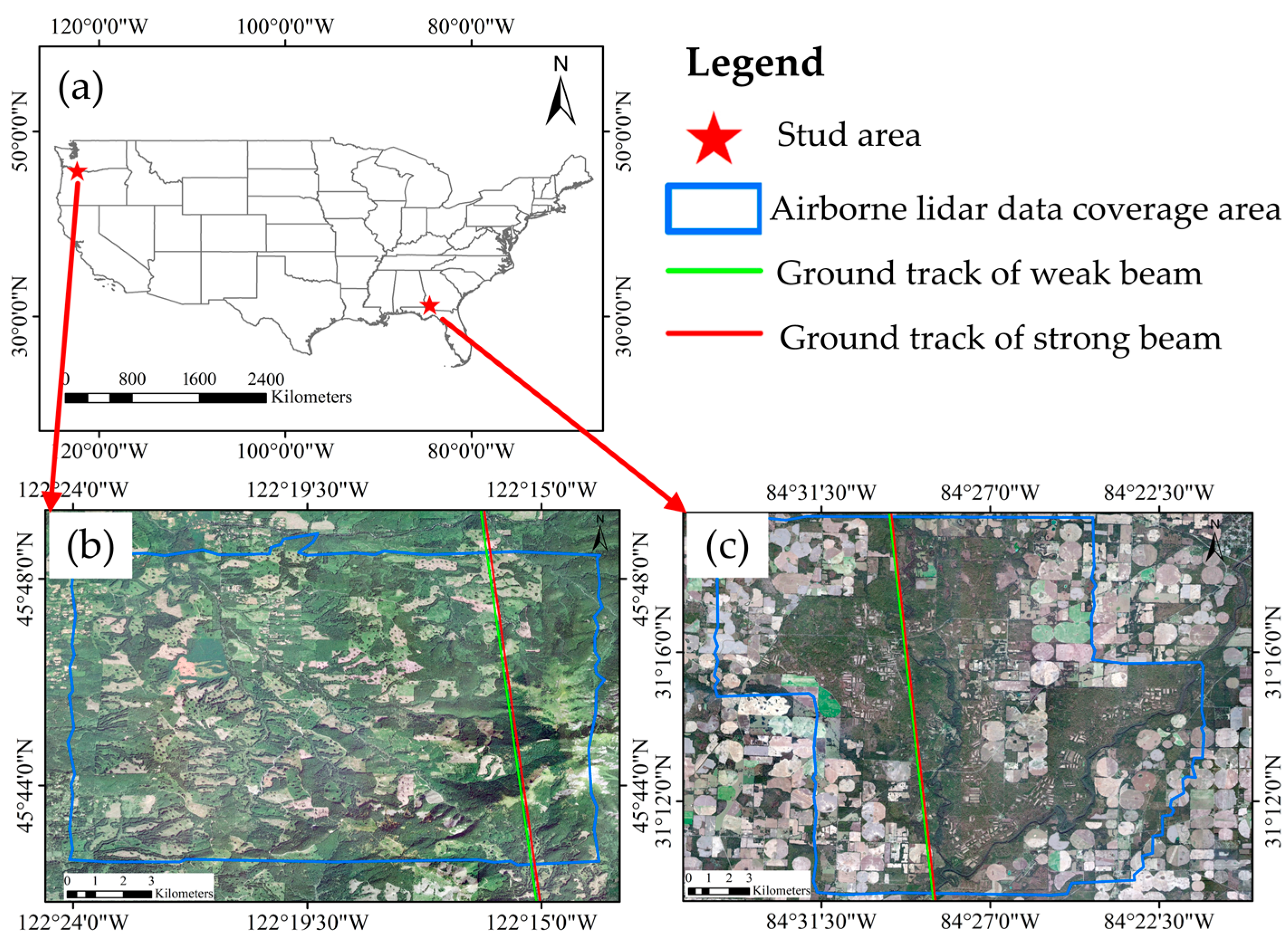
2.1. Study Area

In this study, two study areas are selected, and the specific locations are shown in Figure 1. Among them, study area 1 is located in the southwest of Washington State and it is characterized by a subtropical humid climate. The average annual precipitation in study area 1 is 2450 mm, the average annual temperature is 10 °C, and the altitude range is between 365–708 m. There are three main vegetation cover types in the area: evergreen forests, grassland, and shrubs, with an average canopy height of 34 m. Study area 2 is located in the southwest of Georgia, with a subtropical humid climate. The precipitation is evenly distributed throughout the year, with an average annual precipitation of 1308 mm, an average annual temperature of 19.2 °C, and an altitude range of 47–55 m. The main vegetation cover types are cultivated crops, deciduous forests, evergreen forests, and mixed forests, with an average canopy height of 27 m.

2.2. Data

2.2.1. ICESat-2/ATLAS Data

The emission frequency of an ICESat-2/ATLAS laser pulse is 10 kHz, and a single laser beam can be subdivided into three groups of six-beam laser beams through diffractive optical elements. The inter-track spacing between each group and the inter-track spacing of the group are approximately 3.3 km and 90 m, respectively. Each group of laser beams contains strong and weak beams. The energy ratio of a strong beam to a weak beam is 4:1. It is capable of obtaining the overlapping light spots with an orbital spacing of approximately 0.7 m and a diameter of approximately 17 m, and the plane positioning accuracy is greater than 6.5 m [21,22]. The global geo-located photon data (ATL03) and the land vegetation elevation data (ATL08) of the two study areas were obtained for the purpose of this study and downloaded from the Earth Science Data Systems (ESDS) Program website (https://search.earthdata.nasa.gov/, accessed on 1 May 2022). Among them, ATL03 data provide information on the time, longitude, latitude, and elevation of each photon. ATL08 data are based on ATL03 data and utilize the difference, regression, and Gaussian adaptive nearest neighbor algorithms in order to denoise the photons. It then uses the official NASA classification algorithm to classify the denoised photons, which are divided into noise photons, ground photons, canopy photons, and canopy top photons [23]. The detailed information for ICESat-2/ATLAS data is shown in Table 1.

2.2.2. Airborne LiDAR Data
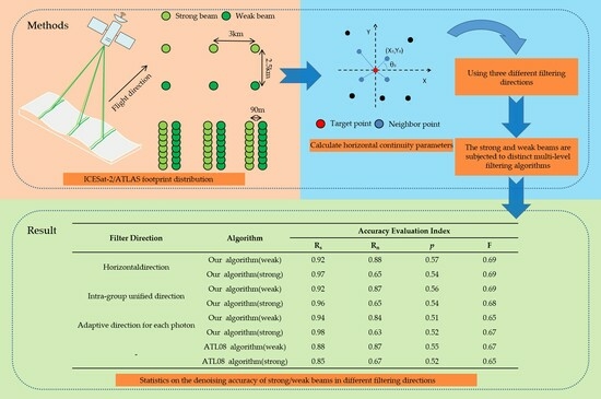
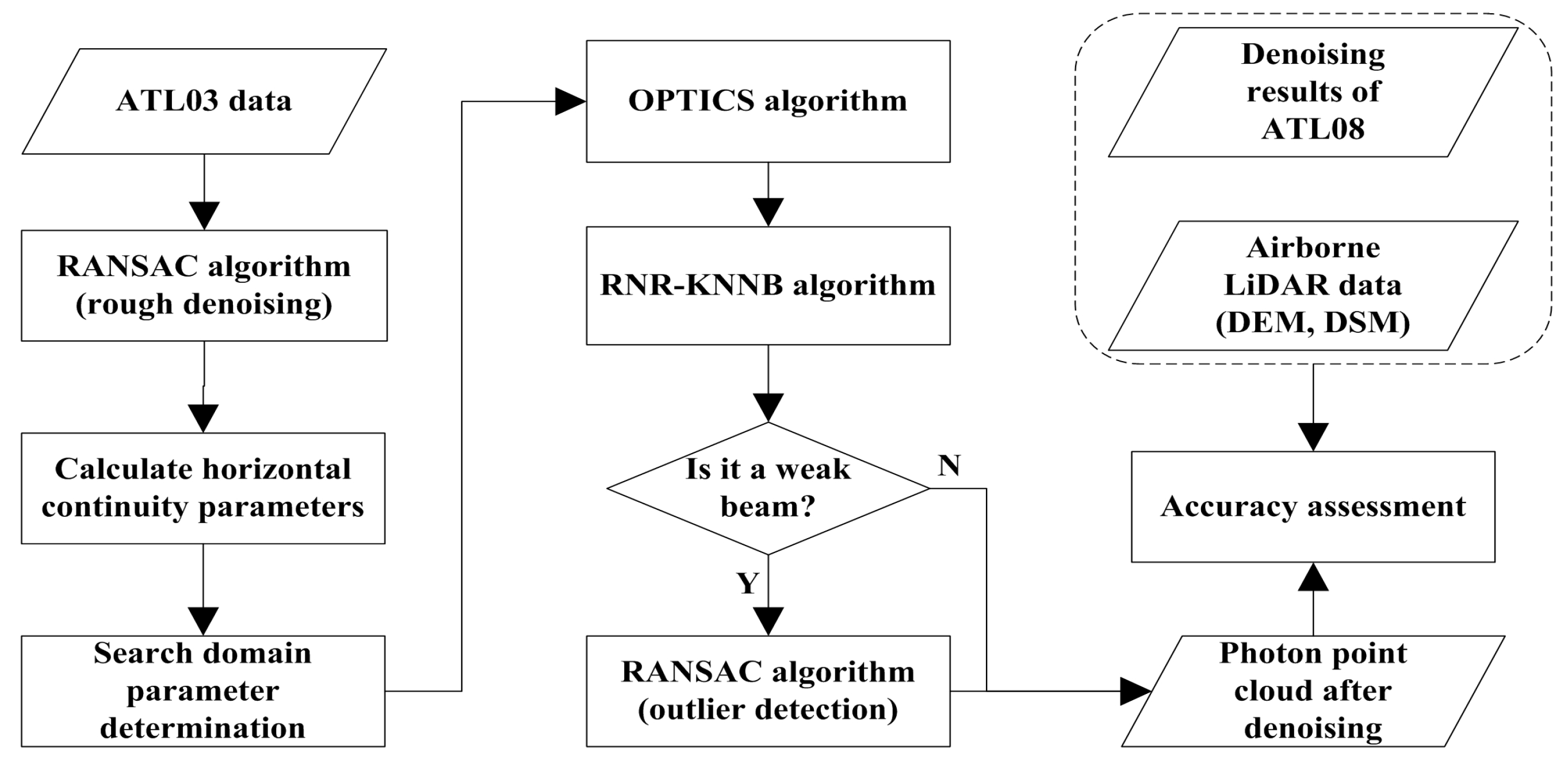
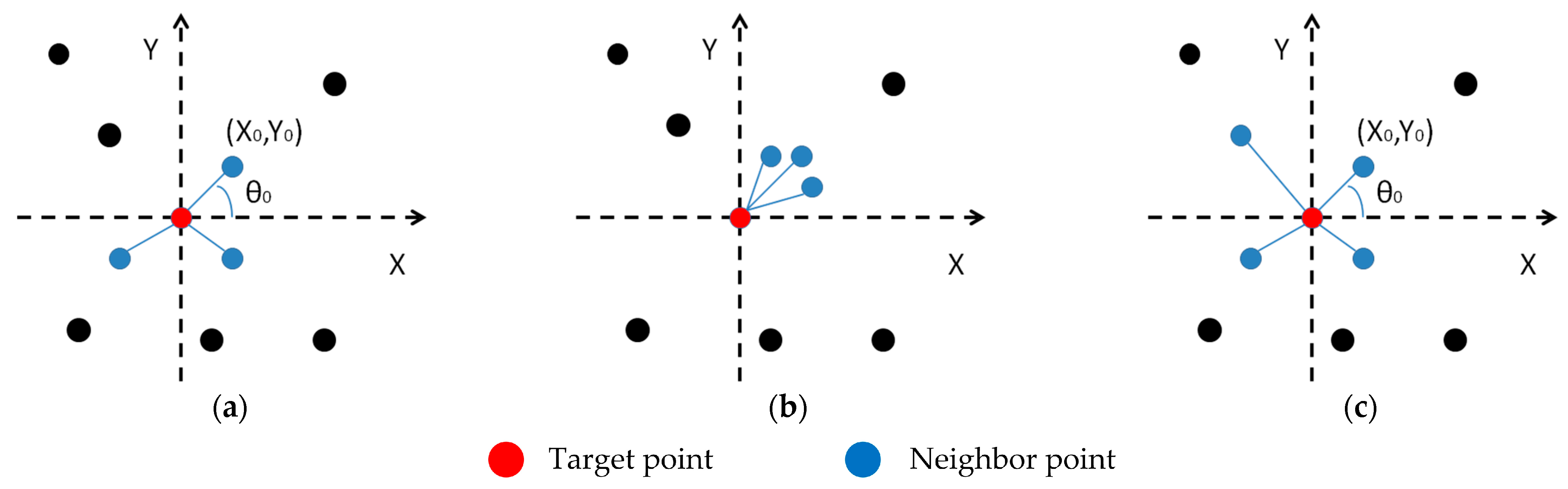
As a means to evaluate the accuracy of the denoising results of the ICESat-2/ATLAS data, airborne LiDAR data were employed in order to derive Digital Terrain Model (DTM) and Digital Surface Model (DSM) products (with a spatial resolution of 1 m) in the study, and they were downloaded from the NEON website (https://data.neonscience.org/data-products/explore, accessed on 1 May 2022). These data are collected by an ALTM Gemini LiDAR sensor with a wavelength of 1064 nm and a pulse frequency of 100 kHz. The horizontal and vertical positioning accuracy are greater than 0.4 m and 0.36 m, respectively [24]. The detailed information for airborne LiDAR data is shown in Table 2.

2.3. Methods

In order to precisely denoise the daytime cloud data of strong and weak beam photons, a multilevel filtering algorithm is proposed. Firstly, the signal photon distribution trend is fitted with the RANSAC algorithm in order to eliminate a major portion of the noise signals. Subsequently, the horizontal continuity parameter is calculated based on the rough denoised photon cloud data, and the shape and size parameters of the search domain of the subsequent fine denoising algorithm are adaptively improved based on the horizontal continuity parameter. Finally, the multilevel filtering algorithm combining the OPTICS density clustering and RNR−KNNB algorithms is used in the three filtering directions to fine denoise the photon cloud data. In addition, the RANSAC algorithm is also utilized in order to remove the outliers after obtaining the weak beam fine denoised point cloud data. The algorithm flowchart is shown in Figure 2.

2.3.1. Rough Denoising

In this study, the RANSAC algorithm is utilized as a means to rough denoise the data by fitting the distribution trend of signal photons. It is based on the principle of iteratively estimating the parameters of the mathematical model from a group of observed data containing outliers. Assuming that the data contain correct data (signal photons) and abnormal data (noise photons), the correct data are recorded as the inner point, and the abnormal data are recorded as the outer point. Regarding the daytime photon cloud data with high background noise, the algorithm is capable of accurately fitting the signal photon distribution trend and removing most noise interference. The following is an overview of the algorithm’s operation:
(1)
The data are divided into windows using the method of equal along-track distance. The photon cloud data are converted into the form of “along-track distance—elevation” and are divided according to the orbital distance interval of 100 m.
(2)
The initialization model is determined, which in this study is a three-parameter curve fitting model, whose equation is shown in Formula (1). Then, three non-repeating points are randomly selected from each window as a subset, and the subsets are used to fit the model in order to obtain the required parameters of the model.
y = A × e B x + C
where x and y represent the along-track distance and elevation values of a photon point and A, B, and C are model fitting parameters.
(3)
The inner point and outer point are divided. The obtained model is then employed in order to check all points. The checking method involves calculating the distance between all points and the vertical direction of the model. When the distance is less than the set threshold, it is marked as an inner point and its number is recorded; otherwise, it is marked as an outer point.
(4)
Updates are made to the optimal model parameters and the corresponding number of the interior points.
(5)
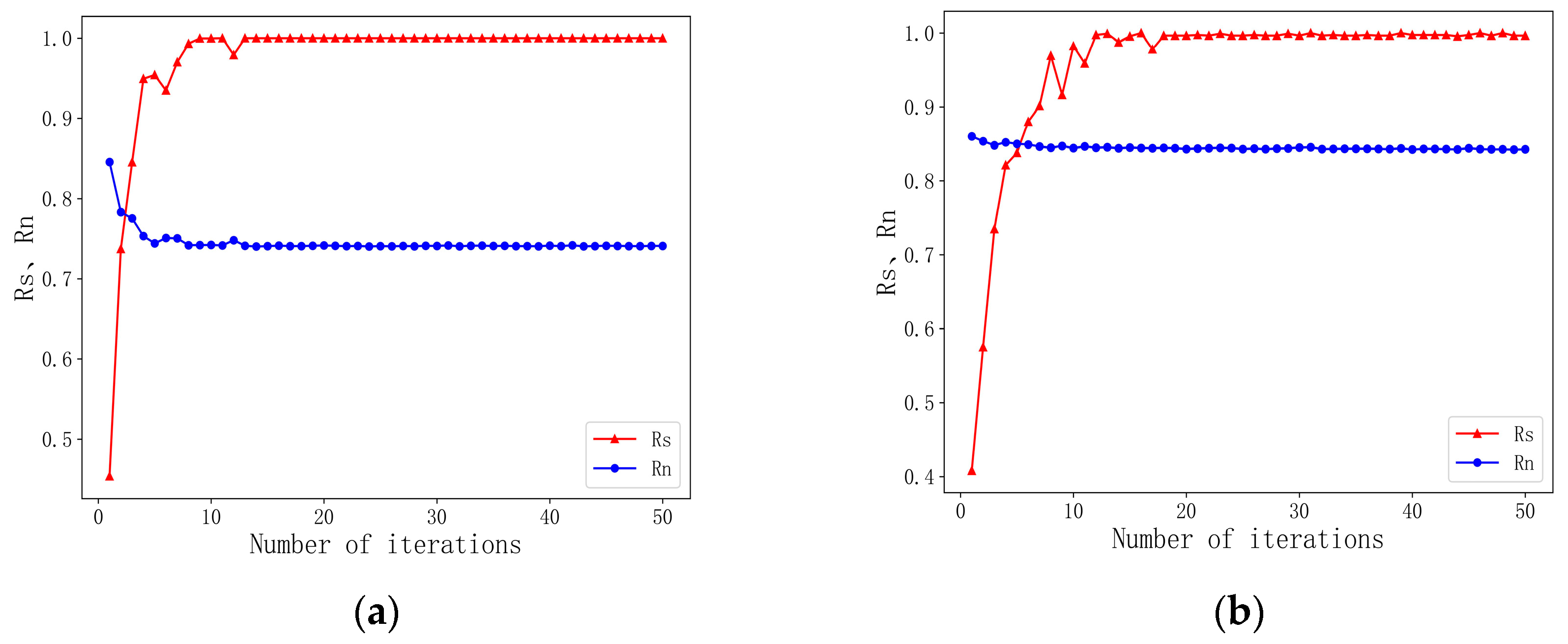
The optimal model is determined. Steps (1) to (4) are then repeated until the maximum number of iterations has been reached. The number of interior points obtained by each model is counted, and the model with the largest number of interior points is recorded as the optimal model and output.

2.3.2. Fine Denoising

After rough denoising, only the range of signal photons is determined, and the noise surrounding the signal cannot be eliminated. In order to obtain high-precision surface structure parameters, further denoising must be applied to the photon data. In this study, the OPTICS density clustering algorithm, the RNR−KNNB algorithm, and the RANSAC algorithm are employed for multilevel processing of rough denoised data. The specific steps are as follows:
(1) Data segmentation. This follows the window division process of the data in the rough denoising step; however, in the fine denoising process, the density clustering and the local distance statistics are adopted for denoising. Considering the influence of the boundary effect, each group of data processed through fine denoising adds 50 m of data on the left and right sides as buffer data, thus obtaining a group of 0–200 m range photon cloud data, but only the processed 50–150 m range data are retained in the end.
(2) Horizontal continuity parameter calculation. Due to the unique data acquisition mode of photon counting LiDAR, the point cloud generally presents stronger continuity in the horizontal direction. However, due to the influence of factors such as diurnal change, vegetation type, and seasonal change, the horizontal continuity of point cloud data also exhibit different characteristics. Accordingly, the horizontal continuity parameter is incorporated in order to evaluate these characteristics [25]. The initial definition of horizontal continuity is to find the three nearest neighbor points to the target point, which are considered to be the most relevant to the target point. The continuity in the horizontal direction was determined by the angle between the line connecting the three nearest neighbor points and the target point and the horizontal direction, as shown in Figure 3a. However, in cases where the direction of the closest points is the same as that of the target point, the difference between the three directional angles calculated from the target point and the nearest neighbor point will be small, making it difficult to evaluate its horizontal continuity, as shown in Figure 3b. Therefore, in this study, we have improved the definition of horizontal continuity. Specifically, taking the target point as the coordinate origin, with the horizontal axis of the target point as the X axis and the vertical axis as the Y axis, the data are divided into four quadrants, and the nearest neighbor points to the target point are found within each quadrant. The continuity in the horizontal direction was determined by the angle between the line connecting the four nearest neighbor points and the target point and the horizontal direction, as shown in Figure 3c. In Figure 3, the red point is the target point, and the blue points are the nearest points to the target point. The direction angle between the nearest point and the target point can be calculated, as shown in Formula (2).
θ = arctan y x
where θ is the direction angle between the target point and the adjacent point and x and y are the horizontal and vertical coordinates of the nearest point, respectively.
The four directions of each target point are then summarized and calculated. The direction angle of 0 or 180 degrees indicates the same elevation as the target point, and the direction angle of 90 degrees indicates the same orbital distance as the target point. The photon-counting radar detector has the characteristic of receiving large echo energies when detecting targets with high reflectivity, resulting in multiple photon attributes being recorded for the same target. As a result, it will appear that the statistical direction angle is always 90 degrees, which accounts for the largest proportion. Accordingly, it is necessary to remove the vertical direction. After removing and normalizing the vertical direction, the direction parameter is defined as the result of a direction angle that is greater than 45 degrees and its weight, minus the result of the direction angle that is less than 45 degrees and its weight, as shown in Formula (3):
t = θ = 0 45 90 θ 90 r θ + θ = 135 180 θ 90 90 r θ θ = 45 90 θ 90 r θ θ = 90 135 180 θ 90 r θ
where t is the direction parameter, θ is the direction angle, and r(θ) represents the proportion of the continuous direction angle θ.
The search domain parameters of the algorithm are determined. This study aims to improve the search domain of the ellipse algorithm, and its search domain parameters include the long axis, the short axis, and the rotation angle of the search domain. The shape parameters of the search field are optimized according to the direction parameters obtained from each window. The larger the t value, the stronger the horizontal continuity of the data, and the weaker the data are. Therefore, it is necessary to set the shape parameters of the search field according to the different beam data and the direction parameters of different windows, as shown in Formula (4):
a = int 10 × 1 t b = int 2 × t
where t is the direction parameter and a and b are divided into long and short axes of the ellipse search domain (the long axis of the weak beam is set to 2a, b ≥ 1).
Three different methods are proposed for determining the filtering direction of the photon points and applied to the daytime strong and weak data denoising results, respectively. (1) The first method only involves the filtering of the data in the horizontal direction. (2) The second method involves filtering the data in adaptive directions for each photon, establishing a search domain based on the target point, traversing 0–180 degrees by an interval of 10 degrees, calculating the photon point cloud density in each direction within the search domain, and finally taking the maximum photon density direction as the filtering direction of the target point, as shown in Formula (5). (3) The third method involves the filtering of the data in the intra-group unified direction. This method relies on the second kind of adaptive direction filtering for each photon in order to carry out statistical analysis. In cases where there is a single peak and the peak direction is within the range of 0–40 and 140–180, the peak direction is employed for processing the data within the group. In cases where there is a double peak or the peak direction is within the range of 40–140, it indicates that there may be a large difference in the direction within the group or the characteristics of the horizontal direction of the data in the group are considered unclear, and thus, the horizontal direction is employed for filtering.
x q = x q x p cos α + y q y p sin α y q = y q y p cos α x q x p sin α d p q = x q a 2 + y q b 2
where α is the filtering direction, x is the distance along the rail, y is the elevation, (xq′, yq′) represents the new coordinates of point q relative to point p under the new coordinate system, d q p is the distance between the two points in the new coordinate system, and in cases where the square of d q p is less than 1, it indicates that the point q is within the search domain of point p.
(3) In this step, the OPTICS density clustering and the RNR−KNNB algorithms are employed. The three filtering directions are processed through the density clustering and the local distance statistical algorithms, respectively. The OPTICS density clustering algorithm includes two parameters, namely the domain radius (ε) and domain minimum points (Minpts). The core distance and reachable distance of each photon point are calculated by setting parameter values; see Formulas (6) and (7) for details. Since there may be multiple reachable distances for photon points, the minimum reachable distance of each point is set as the optimal reachable distance for that point. In previous studies, Wang [25] conducted a sensitivity analysis of the parameter changes in the improved OPTICS-based denoising algorithm. The results have shown that for the OPTICS algorithm, setting different initial parameter values may affect the optimal reachable distance of each photon points, but it does not change the ranking of the optimal reachable distance of all photon points. Therefore, adjusting the initial parameters will not have any impact on the final clustering results. The results indicate that the OPTICS algorithm is insensitive to the setting of initial parameter values. In this study, based on the range of parameter values given in the former similar studies, the ε is set to its maximum value, and the MinPts is set to 10.
C D q = U N D E F I N E D , i f N q < M i n p t s d p q * , i f N q M i n p t s
R D q = U N D E F I N E D , i f N q < M i n p t s max { C D q , d p q } , i f N q M i n p t s
where q* represents the outermost point in the case where the minimum number of points in the domain is reached and N(q) represents the number of photons of the target point q in the point p search domain.
The RNR−KNNB algorithm incorporates the relative neighboring relationship, calculates the relative domain relationship of each photon point and the distance between each photon point and its neighboring points according to the new coordinate system in the filtering direction, and finally obtains the local weighted mean distance of the target point through the local distance weighting calculation method, as shown in Formulas (8)–(10):
γ p q = N q p q , q K
η q = 1 , γ p q < = 0 d p q d p q q , γ p q > 0
S p = 1 K q = 1 K η q d p q
where γ p q is the RNR value between point p and its qth neighbor, K is the number of photon neighboring points counted by local distance, d p q q is the distance between point p (i.e., the qth nearest neighbor of point p) and its pth neighboring point, and ηq is the weight of the distance between the photon point p and its qth neighboring point q. In cases where γ p q is less than or equal to 0, it is taken as 1, and when it is greater than 0, it is taken as the ratio of d p q to d p q q; Sp is the mean value of the local distance-weighted statistical value of point p.
Finally, according to the frequency distribution histogram developed based on the ranking results of the reachable distance obtained by the OPTICS density clustering algorithm and the statistical mean of the local distance of each photon obtained through the RNR−KNNB algorithm, the maximum inter-class variance method is utilized for threshold segmentation. In cases where the reachable distance and local statistical mean are less than the threshold, they are taken as signal photons, and in cases where they are greater than the threshold, they are taken as noise photons.
(4) Abnormal data removal. Since the data have been processed through multistage filtering, the noise impact is small and the signal is more obvious. In order to retain the signal to a large extent and remove the abnormal data, it is necessary to reduce the window size and use the sliding overlapping window in order to process the data (the size was 50 m along the track and advanced forward at a distance of 40 m). By taking the maximum tree height as a reference, the algorithm threshold is reduced (set to 25 m, i.e., in order to retain the data with a width of 50 m) in order to complete the removal of abnormal data.

2.4. Accuracy Evaluation

In this study, a qualitative method and a quantitative evaluation method are employed in order to evaluate the denoising results at all the levels of the multilevel filtering algorithm. The purpose of the qualitative evaluation method is to evaluate the overall quality of the denoising algorithm results through visual judgment. The purpose of the quantitative evaluation method is to employ the DTM and DSM results of airborne LiDAR data as the evaluation criteria for the noise removal accuracy of the photon cloud. The “DTM − 0.5 m” and “DSM + 0.5 m” are employed as the ground boundary and the top boundary of the canopy, respectively. The points within the boundary of both sides are signal photons, and the points outside the boundary are noise photons [26]. The evaluation indicators used in this study primarily include recall (R), precision (P), and comprehensive evaluation index value (F). Furthermore, the recall rate is divided into a signal photon recall rate (Rs) and a noise photon recall rate (Rn). The specific calculation formulas are shown in Formulas (11)–(14):
R s = T P T P + F N
R n = T N T N + F P
P = T P T P + F P
F = 2 R S P R S + P
where TP represents the number of signal photons correctly identified, TN represents the number of noise photons that were correctly identified, FP represents the number of photons divided into signal photons, and FN represents the number of photons that were mistakenly divided into noise photons.

3. Results

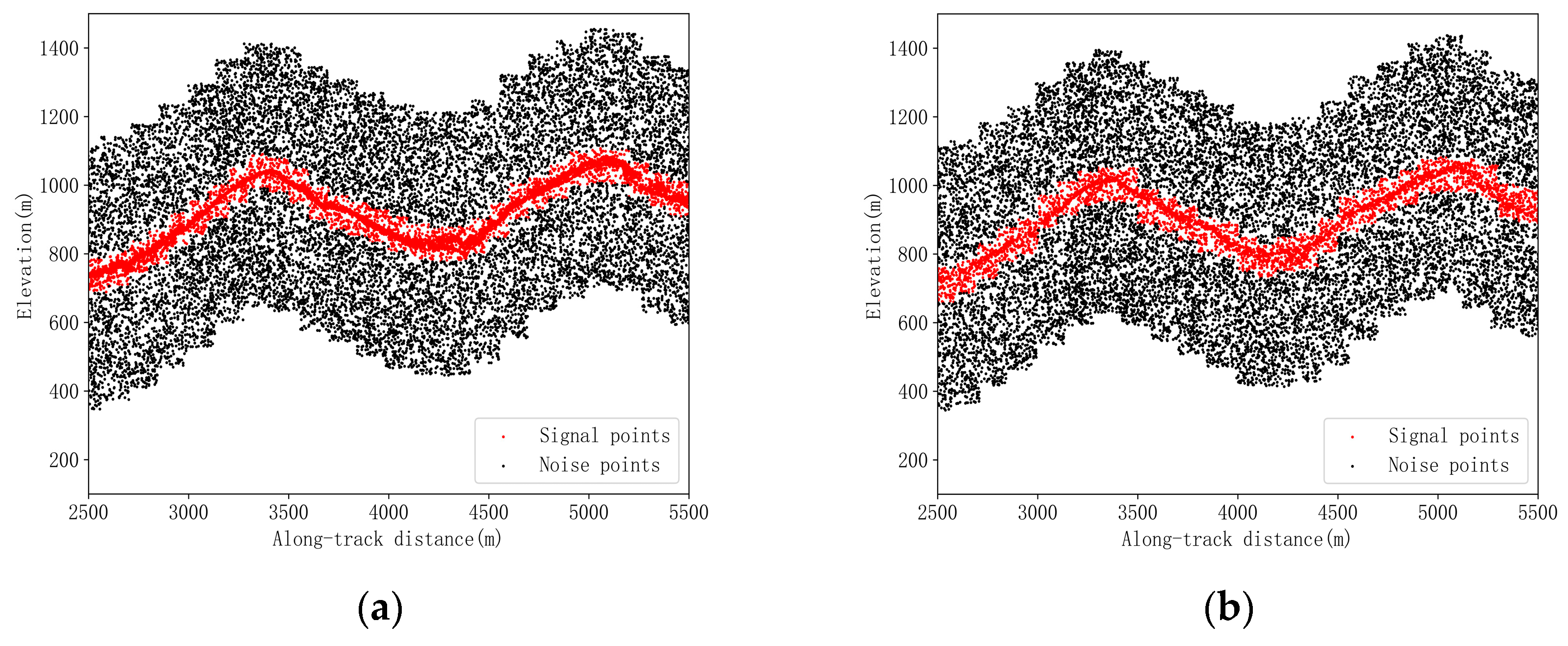
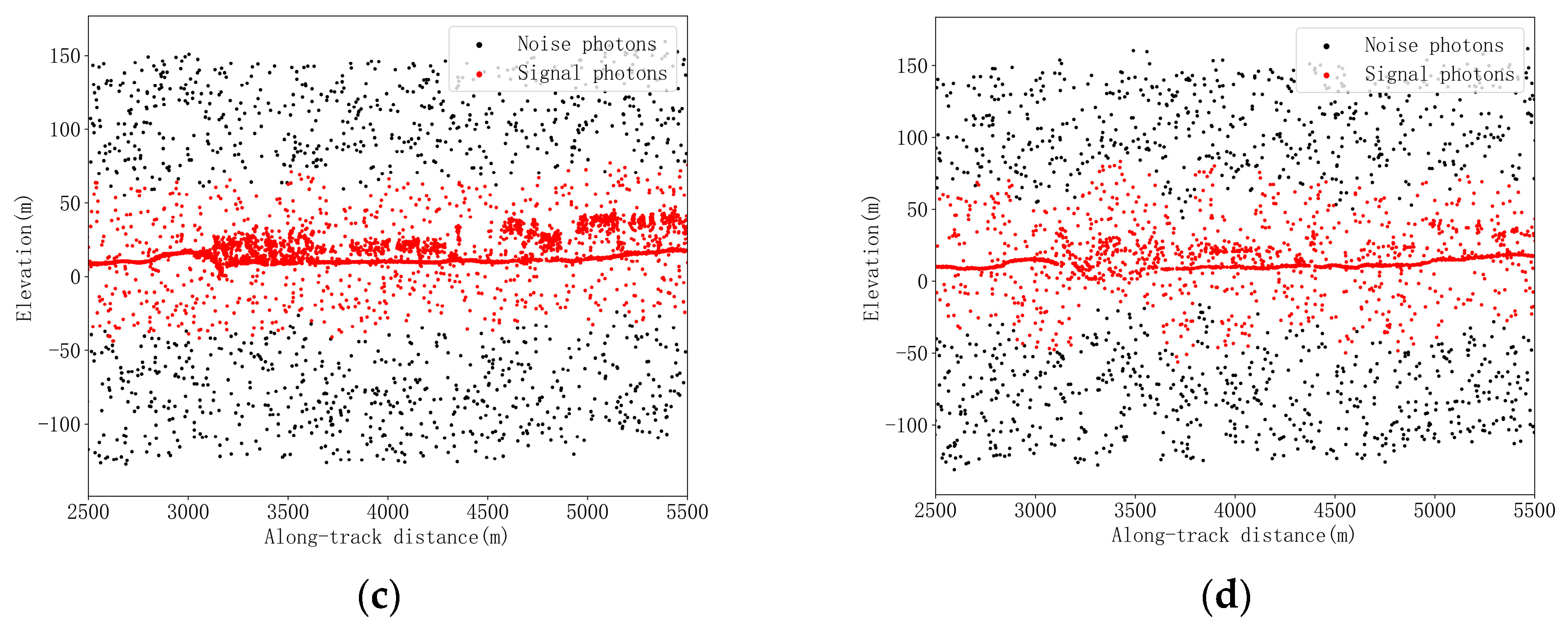
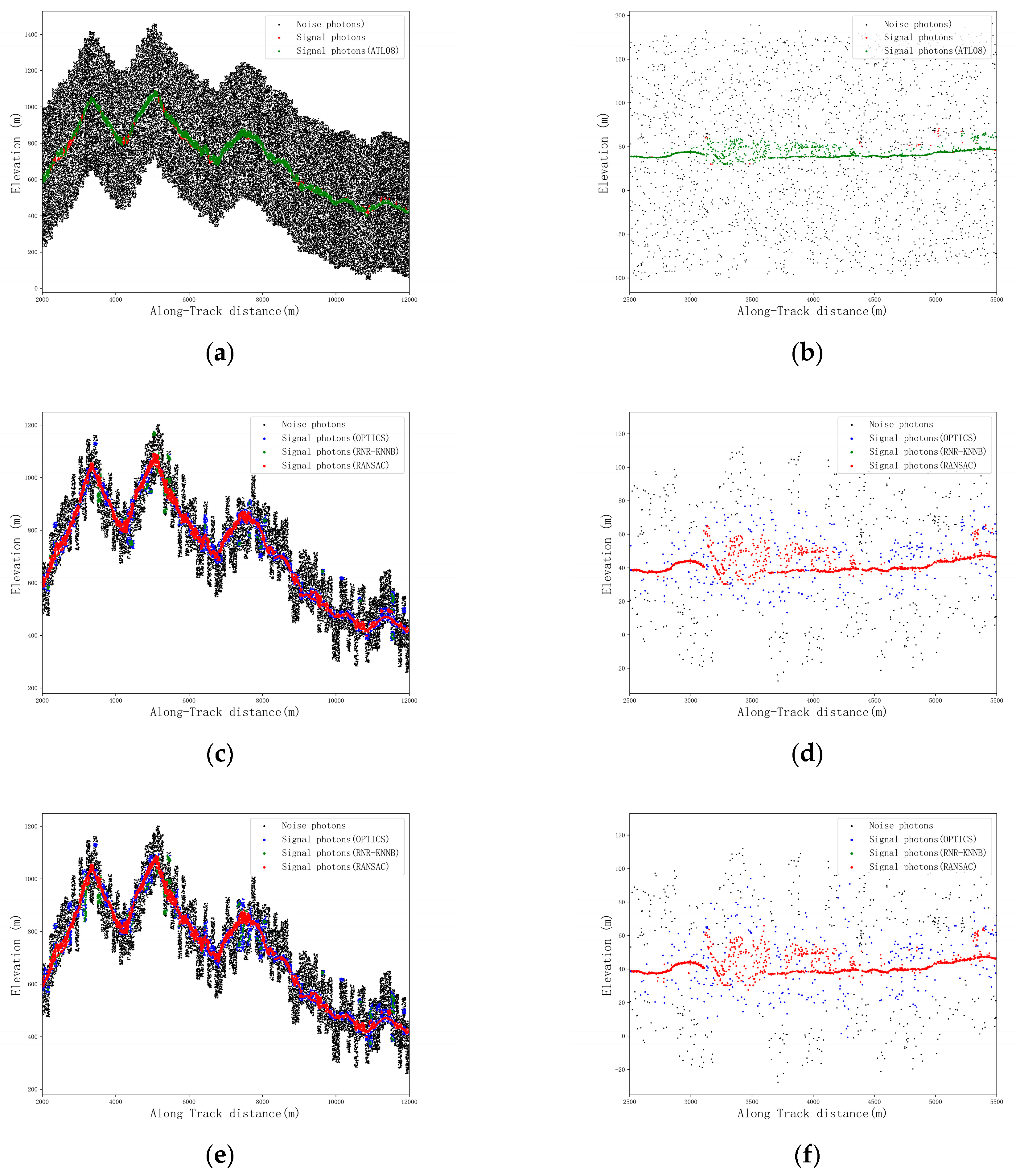
3.1. Rough Denoising Results of the Daytime Strong and Weak Beam Photon Cloud Data

In order to select a reasonable number of iterations, the results of the RANSAC algorithm under different iterations were shown in Figure 4.
According to the results shown Figure 4, it can be seen that for strong and weak beams, the denoising results of the RANSAC algorithm tend to be stable when the number of iterations is greater than 20, that is, the Rs and Rn values of the denoising results no longer changed or changed slightly.
The rough denoising results of strong and weak beam photon cloud data under daytime conditions based on the optimal iteration number of the RANSAC algorithm are shown in Figure 5.
According to the results shown in Figure 5, it is evident that the RANSAC algorithm is capable of effectively removing the majority of the obvious noise points; however, there are still many noise points that need to be further fine denoised. Since rough denoising only establishes a buffer for signal photons and obtains a rough signal photon range, only Rs and Rn are utilized in the quantitative evaluation. The results are shown in Table 3.
According to Table 3, it is evident that the Rs of both strong and weak beam data are 1, and the Rn are greater than 0.29, indicating that the RANSAC algorithm is capable of accurately fitting the signal distribution trend without causing signal photon loss, and can also remove most of the noise. By comparing the Rs and Rn (0.61/0.70 and 0.29/0.52, respectively) of the strong and weak beam in study area 1 and study area 2, it can be seen that the Rn of the weak beam is greater than that of the strong beam, mainly because the energy of the strong beam is higher, and thus, the impact of the noise is greater. Accordingly, in cases where the RANSAC algorithm is employed for rough denoising in order to preserve the equidistant signal range, the noise density of the strong beam is higher, making its noise recall lower than that of the weak beam.

3.2. Fine Denoising Results of the Daytime Strong and Weak Beam Photon Cloud Data

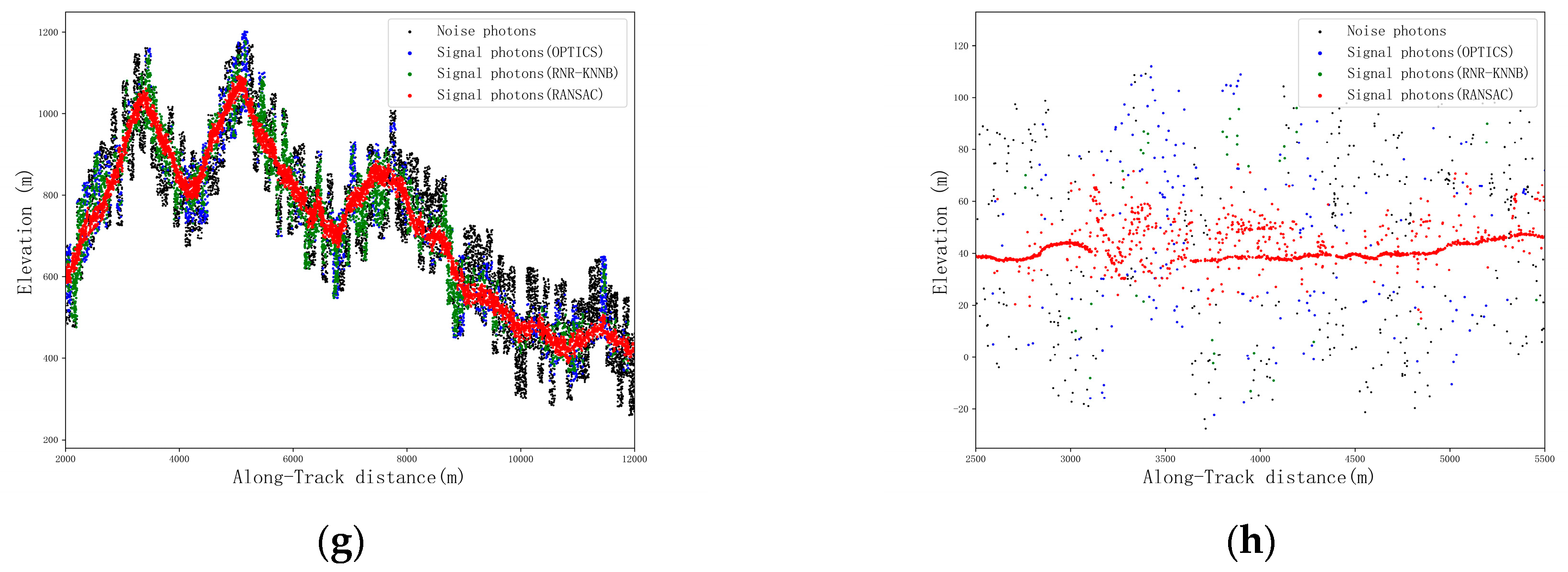
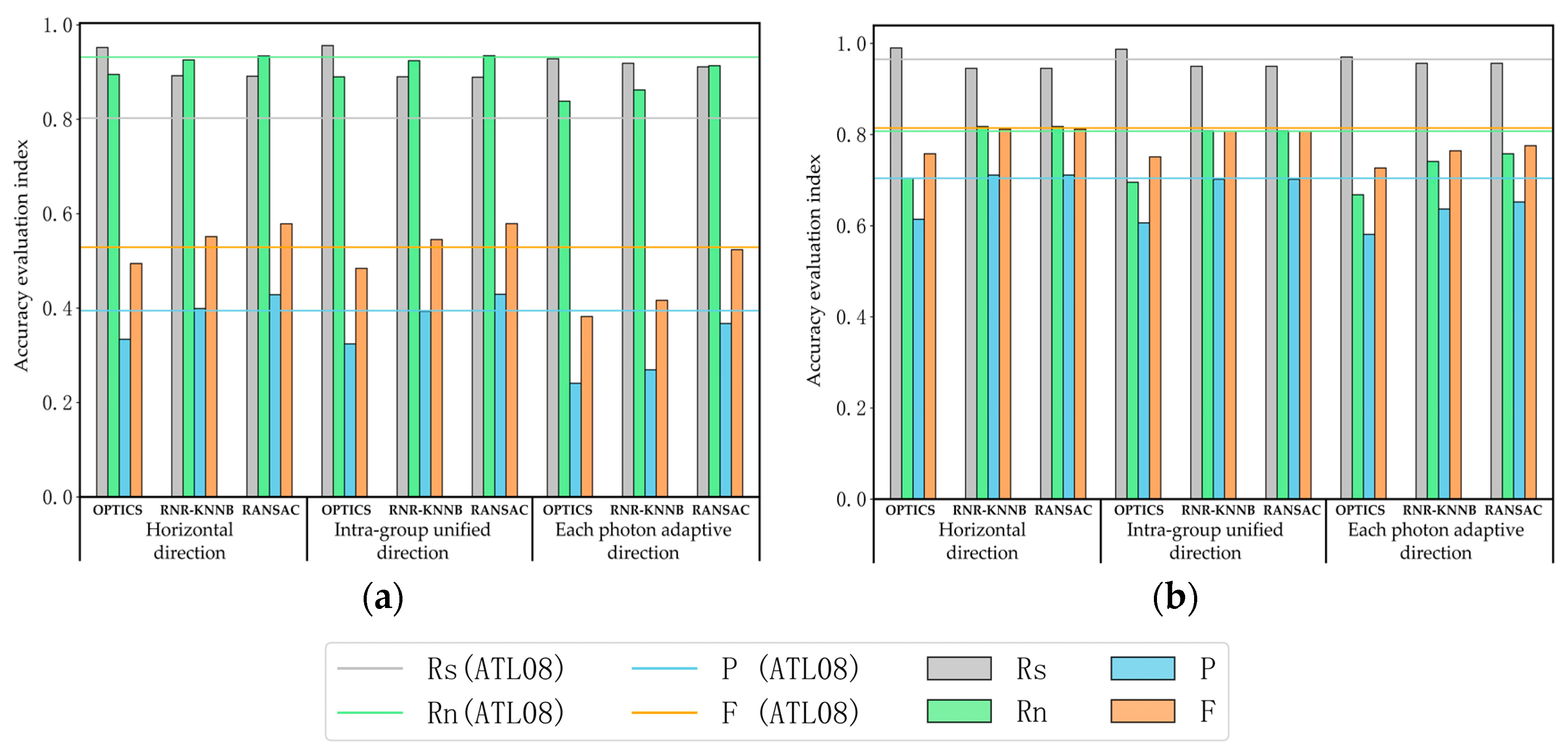
3.2.1. Fine Denoising Results of Strong Beam Photon Cloud Data

Based on the above analysis, it is evident that most of the obvious noises have been filtered out through rough denoising. However, the results still need to be further processed in order to complete the fine denoising of the data. In the case of fine denoising of the strong beam data, a multilevel filtering algorithm combining the OPTICS density clustering and the RNR−KNNB algorithms in the three filtering directions is employed. The results of signal photon extraction based on DTM and DSM data of airborne LiDAR for strong beam data in study area 1 and study area 2, as well as the denoising results of strong beam data obtained using the ATL08 algorithm and the fine denoising results of strong beam data in three different directions using multilevel filtering algorithm, are shown in Figure 6.
According to the results shown in Figure 6, it is evident that most of the noise photons in the strong beam data can be removed after being processed by the OPTICS density clustering algorithm in three search domain directions. The denoising results in the horizontal direction and the uniform direction in the group are similar, and the filtered signal photon band width is smaller than the result of the case with adaptive directions for each photon. However, there are still outlier photon clusters, and the residual noise of the adaptive direction of each photon is mostly distributed around the signal. Additionally, compared to the other two directions, there are more scattered points in the denoised results of the adaptive direction for each photon. After the RNR−KNNB algorithm denoising process, the denoising results obtained in the horizontal direction and the uniform direction within the group are capable of removing the residual outlier noise photon clusters of the upper filter and the noise photons around the signal photon, and the adaptive direction filtering of each photon can also remove the noise signal around the signal photon. According to the results shown in Figure 6a,b, it is evident that in the area with complex terrain and steep slopes, the ATL08 denoising algorithm is not capable of accurately identifying the signal photons, resulting in a large number of signal losses. On the contrary, the multilevel filtering algorithm proposed in this study is capable of effectively identifying the signal photons regardless of the filtering direction.
In this study, the denoising results of the strong beam obtained through the multilevel filtering algorithm and the ATL08 denoising algorithm in two study areas are compared in order to quantitatively analyze the denoising accuracy of the filtering results at all levels of the multilevel filtering algorithm, as shown in Figure 7.
According to the results shown in Figure 7, it can be concluded that after implementing the single-level OPTICS algorithm in horizontal direction, intra-group unified direction, and adaptive directions for each photon, the denoising accuracy in study area 1 exhibits higher Rs and F-values compared to the ATL08 algorithm. In study area 2, the denoising accuracy also demonstrates higher Rs values compared to the ATL08 algorithm. The results indicate that, in comparison to the ATL08 algorithm, the single-level OPTICS density clustering algorithm is capable of retaining signal photons to a greater extent and can achieve a higher denoising accuracy. As compared to the accuracy evaluation index of the OPTICS filtering results, the RNR−KNNB filtering algorithm in all directions is capable of obtaining higher Rn, p-, and F-values on the basis of the previous filtering algorithm, whereas Rs exhibits a small decline and is still higher than the ATL08 denoising algorithm. The results indicate that after implementing the two-level RNR−KNNB filtering, the signal photons can be retained to a large extent, the recognition of noise signals can be strengthened, and a greater degree of denoising accuracy can be achieved.
The average denoising accuracy of the strong beam obtained through the multilevel filtering algorithm at all levels and the ATL08 algorithm in the two study areas is shown in Table 4.
According to Table 4, it is evident that the denoising accuracy (Rs/Rn/p/F) of the single-level filtering process with the OPTICS density clustering algorithm in the horizontal direction, intra-group unified direction, and adaptive directions for each photon are 0.99/0.60/0.51/0.67, 0.99/0.61/0.51/0.67, and 0.99/0.60/0.50/0.65, respectively, and the denoising accuracy of the RNR−KNNB algorithm is 0.97/0.65/0.54/0.69, 0.96/0.65/0.54/0.68, and 0.98/0.63/0.52/0.67, respectively. Among them, the denoising accuracy of each level in the multilevel filtering using the horizontal direction and the intra-group unified direction is similar. Moreover, the Rs of the RNR−KNNB filtering results are slightly lower than those of the former OPTICS filtering results, although the Rn, p-, and F-values are improved. As compared to the former OPTICS filtering results, the RNR−KNNB filtering results in adaptive directions for each photon also produced similar Rn, p-, and F-values, while the Rs remained unchanged. Accordingly, it is evident that the RNR−KNNB algorithm in adaptive directions for each photon is capable of retaining the signal photon to a greater extent and can accurately identify noise signals in the case where the daytime strong beam data were processed. As compared to the denoising accuracy of the ATL08 algorithm, it can be concluded that the Rs and F-values of the OPTICS density clustering algorithm in the three directions obtained after implementing single-level filtering are more accurate than the results of the ATL08 algorithm. Furthermore, the Rs, p-, and F-values obtained through the RNR−KNNB algorithm are also higher than those of the ATL08 algorithm.

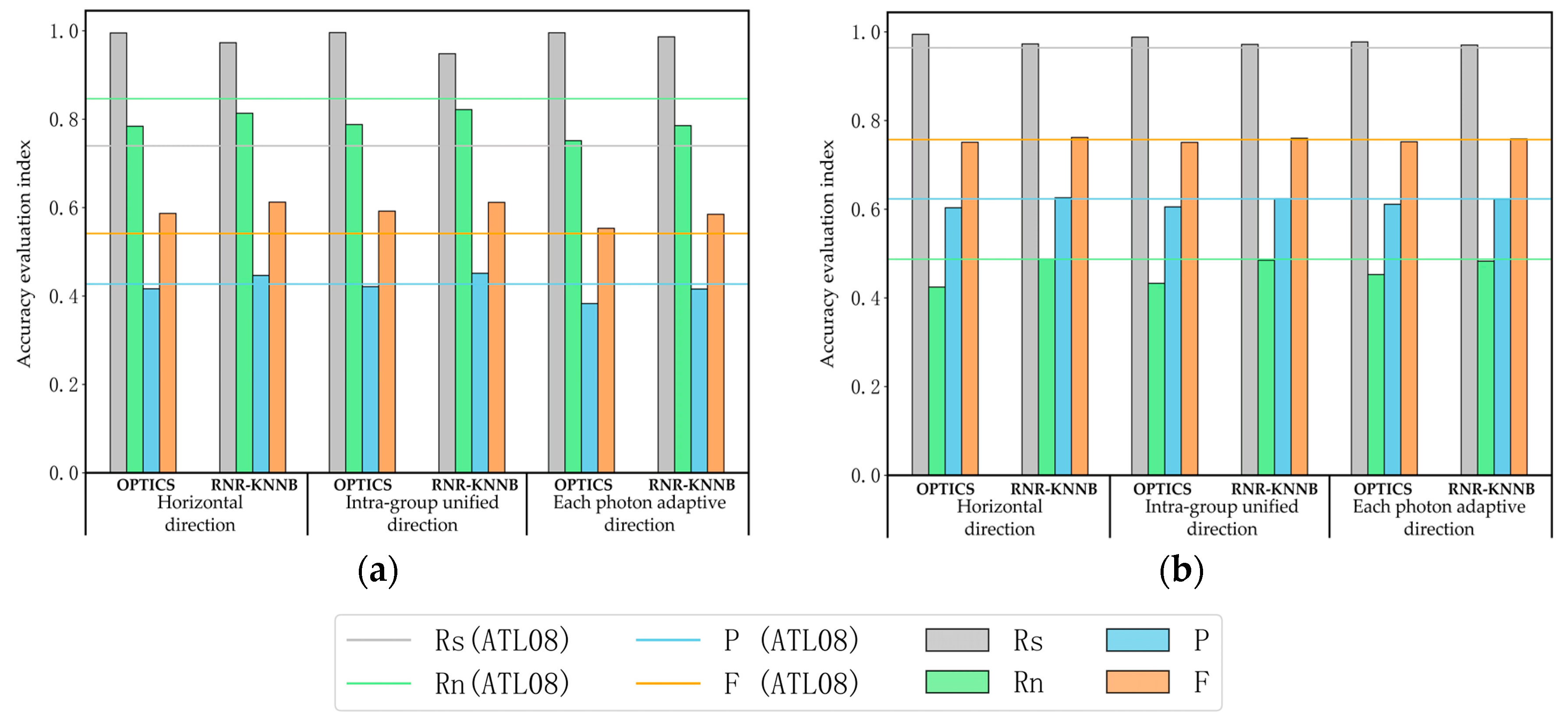
3.2.2. Fine Denoising Results of Weak Beam Photon Cloud Data

An additional single-level outlier detection algorithm was added to the weak beam photon cloud data filtered through the OPTICS algorithm and the RNR−KNNB algorithm in the three filtering directions, which is different from the fine denoising of the strong beam photon cloud data, i.e., the RANSAC algorithm is implemented in order to detect the outliers of the fine denoised data. The results of signal photon extraction based on DTM and DSM data of airborne LiDAR for weak beam data in study area 1 and study area 2, as well as the denoising results of weak beam obtained using the ATL08 algorithm and the fine denoising results of weak beam in three different directions using the multilevel filtering algorithm, are shown in Figure 8.
The results shown in Figure 8 demonstrate that it is possible to remove the majority of the noise through the OPTICS density clustering algorithm in the horizontal direction and the intra-group unified direction. However, in the case of adaptive directions for each photon, there are still many noise signals that cannot be removed. The residual noise surrounding the signal photons and outlier noise can be removed to a certain extent by employing the RNR−KNNB algorithm in horizontal and intra-group unified directions, but some obvious outlier noise photons still remain in the results. In the case of the RNR−KNNB algorithm with adaptive directions for each photon, numerous noise photons are retained in the final results. The results indicate that the filtering results of the three directions still require further denoising. Therefore, the RANSAC algorithm is employed as a means to remove abnormal data from the filtering results in three directions. Based on Figure 8, it is evident that the RANSAC algorithm exhibits an efficient removal effect on outlier abnormal data. As shown in Figure 8a,b, the ATL08 denoising algorithm is not capable of effectively identifying signal photons, resulting in signal loss, which is consistent with the situation in the same range along the track of the previous strong beam. In addition, the ATL08 denoising algorithm is also unable to correctly identify signal photons in complex terrain areas, regardless of whether it is a strong beam or a weak beam. On the other hand, the algorithm proposed in this study is fully capable of effectively preserving the signal photons in this process.
The denoising results of the weak beam data with the multilevel filtering algorithm and the ATL08 denoising algorithm in the two study areas are compared and shown in Figure 9.
According to the results shown in Figure 9, it can be concluded that after implementing the single-level OPTICS density clustering algorithm in the horizontal direction, intra-group unified direction, and adaptive directions for each photon, the denoising accuracy in the two study areas exhibit a higher Rs than that of the ATL08 denoising results, even though the other accuracy indicators are lower than that of the ATL08 denoising results. The results demonstrate that although it is possible to retain more signal photons after filtering them through the single-level OPTICS clustering algorithm, the recognition accuracy of the noise photons is low, and the overall denoising accuracy is weaker than that of the ATL08 denoising algorithm. In study area 1, as compared to the denoising results of the ATL08 algorithm, the denoising results of the RNR−KNNB algorithm in the horizontal direction and the intra-group unified direction produce higher Rs and F-values and similar Rn and p-values, while the denoising results of the RNR−KNNB algorithm in adaptive directions for each photon produce higher Rs, but the other indicators are lower than the ATL08 algorithm. In study area 2, the denoising results of the RNR−KNNB algorithm in the horizontal direction and the intra-group unified direction are similar to those of the ATL08 algorithm, while the denoising results of the RNR−KNNB algorithm in the adaptive directions for each photon are lower than those of the ATL08 algorithm. In comparison to the results of the superior filtering algorithm, there is a slight decrease in the Rs of the RNR−KNNB algorithm in the horizontal direction and the intra-group unified direction. However, the other indicators were improved, and compared to the ATL08 algorithm, it is capable of achieving similar or even a higher degree of denoising accuracy. The denoising accuracy of the RNR−KNNB algorithm in the adaptive directions for each photon exhibits a certain degree of improvement as compared to the previous filtering algorithm, but it is still weaker than that of the ATL08 algorithm. In study area 1, as compared to the denoising results of the superior filtering algorithm, the RANSAC algorithm was utilized in order to remove abnormal data, and thus, the results were significantly improved, except that the Rs remained unchanged. Compared with the results of the ATL08 algorithm, the denoising accuracy of the horizontal direction and the intra-group unified direction is higher, while the denoising accuracy of the adaptive directions for each photon produce higher Rs and similar F-values, and the other indicators are lower than that of the ATL08 algorithm. In study area 2, the denoising accuracy of the horizontal direction and the intra-group unified direction is similar to that of the ATL08 algorithm, while the accuracy evaluation indexes of the adaptive directions for each photon are lower than that of the ATL08 algorithm. The results demonstrate that the RANSAC algorithm is capable of effectively retaining the signal photons as well as eliminating the abnormal noise data retained by the RNR−KNNB algorithm.
The average denoising accuracy of the weak beam with the multilevel filtering algorithm at all levels and that of the ATL08 algorithm in the two study areas are shown in Table 5.
According to Table 5, it is evident that the denoising accuracy (Rs/Rn/p/F) of the single-level filtering process with the OPTICS density clustering algorithm in the horizontal direction, intra-group unified direction, and adaptive directions for each photon are 0.97/0.80/0.47/0.63, 0.97/0.79/0.46/0.62, and 0.95/0.75/0.41/0.55, respectively, and the denoising accuracy of the RNR−KNNB algorithm is 0.92/0.87/0.55/0.68, 0.92/0.87/0.55/0.68, and 0.94/0.80/0.45/0.59, respectively. The accuracy after removing the abnormal data through the RANSAC algorithm is 0.92/0.88/0.57/0.69, 0.92/0.87/0.56/0.69, and 0.94/0.84/0.51/0.65, respectively. As compared to the denoising accuracy of the ATL08 algorithm, it can be concluded that only the Rs value of the OPTICS density clustering algorithm in the three directions after performing the single-level filtering is superior to the results of the ATL08 algorithm. Higher Rn, p-, and F-values were obtained through the RNR−KNNB algorithm, among which the denoising results in the horizontal direction and the intra-group unified direction are more accurate than those of the AT08 algorithm, and only the Rs value in the denoising results of the adaptive directions for each photon is higher than those of the above two filtering directions. The Rn, p-, and F-values in the filtering results of the RNR−KNNB algorithm are lower than those of the ATL08 algorithm, indicating an inferior degree of denoising accuracy. After implementing the RANSAC algorithm as a means to eliminate abnormal data, the filtering results of the horizontal direction and the intra-group unified direction are superior to the denoising results of the ATL08 algorithm, while the denoising results of the adaptive direction for each photon are improved, except that the Rs value remains unchanged, but it is still lower than the denoising results of the ATL08 algorithm. Based on the qualitative analysis, it can be concluded that the denoising results of the RNR−KNNB algorithm in the adaptive directions for each photon still exhibit a large number of noise photons that have not been removed. Therefore, after the removal of abnormal data through the RANSAC algorithm, as compared to the horizontal direction and the intra-group unified direction, the denoising results obtained through the adaptive directions for each photon exhibit more residual noise signals around the signal photons, and thus, they show a worse denoising result.

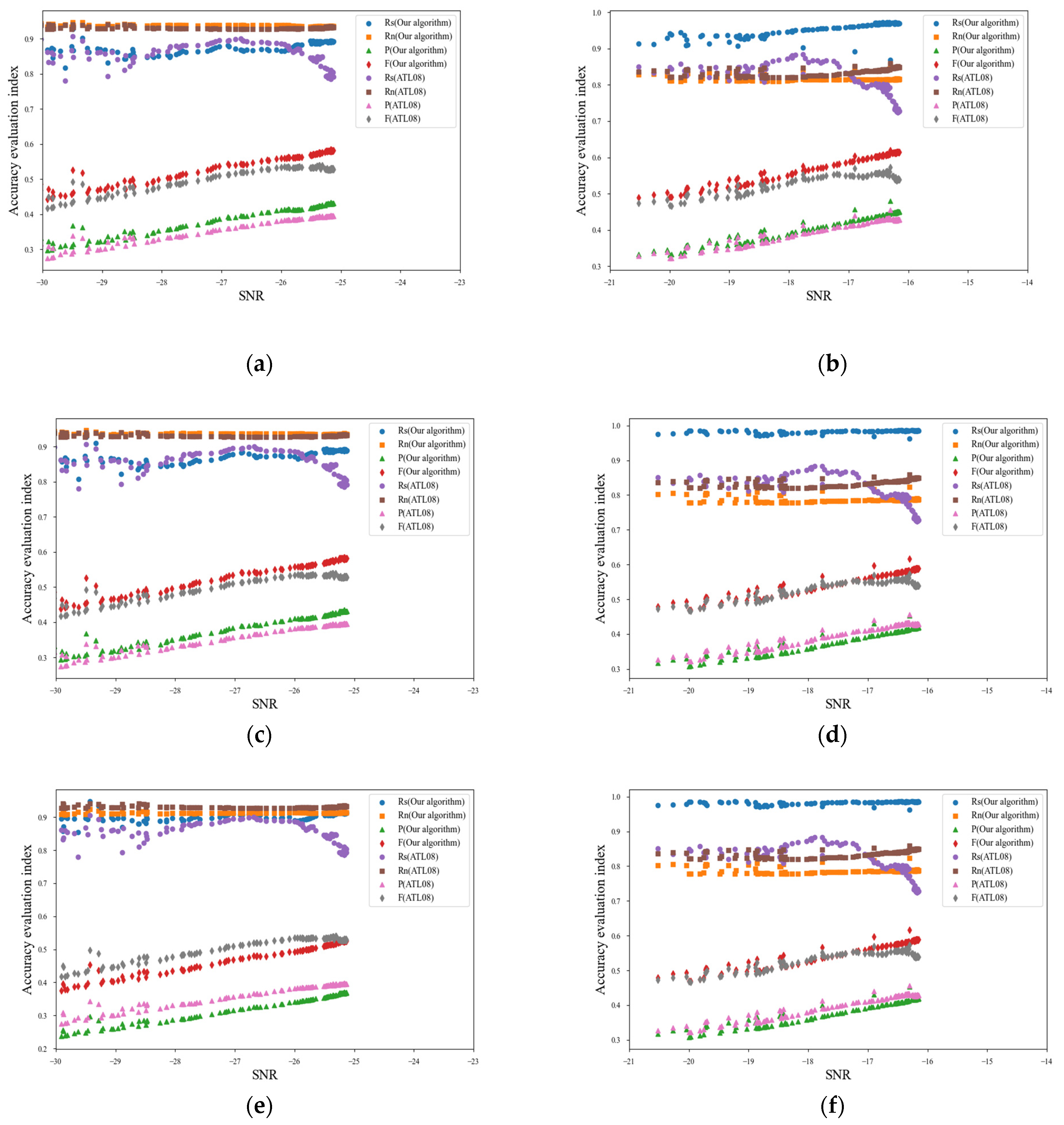
3.3. Denoising Results of Strong and Weak Beam Photon Cloud Data in Different Directions and SNRs

To verify the denoising results of strong and weak beam photon cloud data in different directions and SNRs, the ICESat-2 strong and weak beam photon cloud data were divided into segments every 100 m along the orbit. In total, 100 data segments were selected and the SNR of each segment in different filtering directions was calculated. The calculation formula is shown in Equation (15) [27], and the SNR is ranked in ascending order to establish the correlation between SNR and denoising accuracy. The results are shown in Figure 10.
S N R = 20 × lg N photon N noise
where Nphoton is the number of signal photons and Nnoise is the number of noise photons.
According to the results shown in Figure 10, the SNR of strong beams is greater than that of weak beams, indicating that strong beam data have higher quality. As the SNR increases, the p- and F-values of the denoising results also increase. The multilevel filtering algorithm proposed in the study can obtain high and stable Rs and Rn values, while the Rs obtained with the ATL08 algorithm changes significant. For example, for weak beams, analyzing the denoising results in the horizontal direction and the intra-group unified direction shows that as the SNR increases, the p- and F-values of the multilevel filtering algorithm gradually increase, and both are higher than the p- and F-values of the ATL08 algorithm. Under different SNRs, the Rs and Rn values of the multilevel filtering algorithm tend to stabilize, and both are better than the results of the ATL08 algorithm. The results show that the multilevel filtering algorithm can retain more signal photons while possessing stronger noise recognition ability. However, by analyzing the results in the adaptive direction for each photon, the Rs and Rn of the multilevel filtering algorithm still maintain a high and stable state with the increase of SNR, but they are lower than the Rn value of the ATL08 algorithm, and the Rs of the ATL08 algorithm show a relatively low and unstable state. The p- and F-values of the two algorithms also increase with the increase of SNR, but the p- and F-values of the multilevel filtering algorithm are lower than those of the ATL08 algorithm. For strong beams, analyzing the denoising results in the horizontal and the intra-group unified direction shows that the Rs value of the multilevel filtering algorithm is significantly better than that of the ATL08 algorithm, and increases with the increase of SNR. However, the Rn value is lower than that of the ATL08 algorithm, but the difference in results is not significant. The results indicate that for strong beams, the multilevel filtering algorithm can retain signal photons to a greater extent and has noise recognition ability similar to the ATL08 algorithm. Moreover, the p- and F-values of the two algorithms gradually increase with the increase of SNR, and the p- and F-values of the multilevel filtering algorithm are higher than those of the ATL08 algorithm. By analyzing the results in the adaptive direction for each photon, the Rs of the multilevel filtering algorithm is higher than that of the ATL08 algorithm, but the Rn is lower than that of the ATL08 algorithm. This is mainly because using adaptive directions for each photon to denoise photon data will enable all photons to obtain their maximum density direction. Although it will improve the ability to retain signal photons, it will also reduce the recognition ability of noise. By analyzing the p- and F-values, it can be seen that the p- and F-values of both algorithms increase with the increase of SNR. Among them, the p-value of the multilevel filtering algorithm is similar to that of the ATL08 algorithm, but the F-value is better than that of the ATL08 algorithm. Especially when the SNR is greater than 17, the F-value of the ATL08 algorithm shows a trend of no increase but rather a decrease, while the F-value of the multilevel filtering algorithm maintains a stable upward trend.
Consequently, the SNR is an important factor affecting the denoising results of algorithms. Specifically, the higher the SNR, the better the data quality, and denoising algorithms can also achieve better denoising results. For weak beams, regardless of the SNR, the denoising accuracy of the multilevel filtering algorithm is better than that of the ATL08 algorithm when using the horizontal direction and the intra-group unified direction. Although more signal photons can be retained when using adaptive directions for each photon, the denoising accuracy of the multilevel filtering algorithm is lower than that of the ATL08 algorithm under different SNR. For strong beams, under different SNRs, multilevel filtering algorithms can achieve higher Rs and similar or even higher F-values than the ATL08 algorithm in all three filtering directions.

4. Discussion

4.1. Analysis of Denoising Results in Different Beam Intensities

Due to the differences between strong and weak beams, the distribution and characteristics of photon counts are not identical. However, previous studies on photon cloud denoising have mostly focused on unified denoising of strong/weak photon clouds, without distinguishing them. For example, Wang et al. [28] used the denoising method based on statistical characteristics to remove noise photons caused by specular reflection from the photon cloud data. The results show that this method can effectively remove the noise photons caused by specular reflection echo from the photon cloud data. Popescu et al. [8] used a multilevel noise filtering algorithm to denoise photon cloud data and utilized an overlapping moving window and cubic spline interpolation method to classify photon cloud data. The results show that the multilevel filtering algorithm can effectively identify background noise photons and preserve signal photons. Qin et al. [29] proposed an improved denoising algorithm, which first analyzes the internal characteristics of photon clouds and adaptively selects the optimal parameters for coarse denoising, and then performs two fine denoising operations. The algorithm successfully removed noise photons from the photon cloud data, and the denoising accuracy is effectively improved with the number of denoising times. The denoising results retain the maximum number of recognizable signal photons. Lao et al. [30] proposed an adaptive method for extracting signal photons. Firstly, based on KNN search and covariance matrix, the first denoising is completed through photon curvature features. Then, the first denoising result is processed using RANSAC and an elevation frequency histogram to obtain the local photon filtering direction and threshold to eliminate locally dense noise photons that cannot be recognized for the first time. The results indicate that the newly proposed algorithm can accurately identify signal photons of different surface types and morphologies, and has good adaptability and robustness. Li et al. [31] proposed a photon denoising method that considers the influence of the density difference between canopy photons and ground photons. The results showed that the average overall accuracy and standard deviation were 0.99 and 0.01, respectively, which is superior to existing filtering algorithms. Moreover, this method can almost completely eliminate the influence of the density difference between canopy photons and ground photons on the filtering results of photon data. Although different algorithms have been employed for denoising photon cloud data and have achieved good results, the aforementioned studies have not conducted differential processing on strong/weak photon cloud data, nor have they studied the impact of differences in intensity of strong/weak photon cloud data on denoising results. On the basis of previous research, this study utilizes a multilevel filtering algorithm to separately denoise photon cloud data of strong and weak beams, in order to study the differences in denoising results between strong and weak photon cloud data. The results demonstrate that the multilevel filtering algorithm can effectively remove noise photons under both strong and weak beam data. However, due to the more distinct photon density characteristics of strong beam data, the algorithm exhibits higher denoising accuracy, while the denoising accuracy of a weak light beam is slightly lower. Additionally, by analyzing the p-value and F-value of the denoising results, it was found that for strong beam photon cloud data, the p-value and F-value are relatively large, indicating that strong beams provide a higher signal-to-noise ratio, making the denoising algorithm easier to distinguish between signals and noise, and achieving higher accuracy and recall. On the contrary, for weak beam photon cloud data, the p-value and F-value are relatively small, indicating that the difference between signal and noise is not significant under weak beams, resulting in relatively low accuracy and recall rates. The results indicate that denoising results for strong beam photon cloud data are more precise than those for weak beam photon cloud data under daytime conditions. It was found that for strong beam data, the density characteristics of signal photons are more prominent, which enables denoising algorithms to better identify and retain signal photons, while reducing false detections and improving the accuracy of denoising. For weak beam data, the characteristics of signal and noise photons are not obvious, the beam intensity is insufficient to effectively distinguish between signal photons and noise photons, or the distribution of noise photons is more random and complex, making it more challenging to distinguish them from signal photons. Therefore, future research should focus on enhancing denoising algorithms for weak beam photon cloud data to further improve denoising results of strong/weak beam photon cloud data, providing high-precision basic data for subsequent photon cloud data classification studies.
To achieve better denoising of strong and weak photon cloud data under daytime conditions, this study proposes a multilevel filtering algorithm. Firstly, the RANSAC algorithm is applied to roughly denoise the daytime photon cloud data with high background noise, and the signal point cloud buffer is established to remove the majority of noise points. Subsequently, the horizontal continuity parameter is calculated according to the photon cloud data following the rough denoising process. Based on this parameter, the shape and size of the search domain of the results of the subsequent fine denoising algorithm are adaptively improved. Finally, a hybrid algorithm combining OPTICS density clustering algorithm and RNR−KNNB algorithm is employed as a means to accurately denoise the photon cloud data in the three filtering directions. Furthermore, the RANSAC algorithm based on a sliding overlap window is utilized in order to remove outliers from the weak beam photon cloud data after the fine denoising process. The results demonstrate that the proposed multilevel filtering algorithm can effectively achieve precise denoising of high-background noise photon cloud data during the daytime, and the results are superior to previous similar photon cloud denoising research results. For example, Zhang et al. [32] proposed a density clustering method based on horizontal ellipse searching, which exhibits good filtering effects in flat areas but struggles to adapt to areas with complex terrains, and the filtering results heavily depend on input parameters. S.C. Popescu et al. [8] proposed an adaptive clustering algorithm that can remove noise photons in most environments, but it faces difficulties in eliminating noise photons near signal photons, exhibits significant dependence on terrain, and has lower filtering efficiency. However, the multilevel filtering algorithm used in this study can adapt to the changes of slope and perform well in areas with complex terrains. Additionally, the separate denoising of weak beam photon cloud data using the RANSAC algorithm based on sliding overlapping windows allows for effective outlier removal, resulting in satisfactory denoising performance under weak beams. Although the proposed multilevel filtering algorithm achieves accurate denoising of daytime high-background-noise photon cloud data, there are still some limitations in denoising weak beam data. Compared to denoising algorithms based on the difference in photon distribution characteristics between signal photon and noise photons, machine learning algorithms have strong learning ability. By training and learning the input point data, they can effectively solve the problems of point cloud data disorder, permutation invariance, and rotation invariance, achieving accurate classification of point cloud data. For example, Meng et al. [33] proposed a back propagation neural network denoising algorithm suitable for ICESat-2 photon data of shallow island and reef areas, and the results showed that the denoising algorithm has good denoising results in shallow island and reef areas. Li et al. [34] used the support vector machine algorithm to classify signal photons and noise photons based on extracting elliptical distance parameters from ICESat-2 photon data in forest areas. The results showed that this method can effectively remove noise photons without relying on any statistical assumptions or thresholds, and the accuracy is higher than 0.98, which is superior to existing algorithms. The above research results indicate that machine learning algorithms can achieve precise classification of signal photon and noise photons by learning the features of each photon point, which is expected to make up for the shortcomings of weak beam photon denoising results. Therefore, in the future, machine learning algorithms can be used for weak beam signal/noise photon classification to improve the denoising results of photon cloud data.

4.2. Analysis of Denoising Results in Different Filtering Directions

In addition to the filtering algorithm and the differences between strong and weak photon cloud data, the filtering direction is also a key factor influencing the denoising results of photon cloud data. For instance, Wang et al. [10] performed directionally adaptive density clustering for fine denoising of point clouds after rough denoising. The results showed that in areas with high slope, when denoising algorithm with a fixed filtering direction was used, some signal points would be lost at the edges. Zhu et al. [18] used ellipse searching to calculate photon density to generate ellipses relative to surface slope, achieving better density statistics and reducing the influence of photon directionality, thereby effectively removing noise photons while preserving signal photons. Although the filtering direction can affect the denoising results of photon cloud data, most previous studies only considered a single filtering direction without considering the impact of different filtering directions on denoising results of photon cloud data. Based on previous research, this study proposed three filtering directions, namely horizontal direction, intra-group unified direction, and adaptive direction for individual photons. For strong beams under daytime conditions, the denoising accuracy of the multilevel filtering algorithm with three directions proposed in this study is superior to that of the ATL08 algorithm in the case where the daytime strong beam was processed. Based on the qualitative and quantitative analyses, it can be concluded that the denoising results of the multilevel filtering algorithm with the horizontal direction and the intra-group unified direction are similar, and the multilevel filtering algorithm with adaptive directions for each photon is capable of retaining more noise around the signal photon; however, there is no obvious outlier noise. There is a possibility that this is due to the stronger ability of the strong beam to describe the surface. Employing the horizontal direction and the intra-group unified direction for filtering may lead to a small amount of noise to produce the filtering direction with the largest photon density. However, the filtering direction of the signal photon is not the best direction, primarily because it reduces the statistical difference between signal and noise photons, thus leading to the existence of a small part of outlier noise. We adopted a method similar to that described in the literature [35], i.e., utilizing adaptive directions for each photon in order to seek out the maximum density direction for filtering. Consequently, both signal and noise photons can obtain their best filtering direction (i.e., the maximum density direction). However, in the case of the photon cloud data in the forest area, the signal points near the canopy top also exhibit a certain degree of continuity in the elevation direction, and utilizing adaptive directions for each photon may lead to incorrectly classifying the noise near the canopy as a signal [10]. After being processed by the secondary filter of the RNR−KNNB algorithm in the fine denoising process, it is possible to effectively remove the outlier noise as well as the noise around the signal photon, regardless of the filtering direction. This is because the RNR definition is introduced in order to describe the relative domain relationship between photons. When calculating the local distance, the distance between two photons is weighted according to the RNR value, which expands the statistical difference between signal photons and noise photons. As a result, noise and signal photons can be effectively distinguished.
For weak beams, both the horizontal direction and the intra-group unified direction produce denoising results that are similar and superior to those of the ATL08 algorithm. However, there are still numerous noise signals that remain after performing the former two levels of the denoising when the adaptive directions for each photon were used. The quantitative analysis demonstrates that only the Rs value in the final denoising results of the adaptive directions for each photon is higher than that of the ATL08 algorithm, and the other accuracy evaluation indicators exhibit values that are lower than those of the ATL08 algorithm and the filtering algorithms in the horizontal direction and intra-group unified direction. The above results are explained by the relatively low laser intensity of the weak beam in comparison to the strong beam, and by the fact that the density difference between the signal photon and the noise photon is not noticeable during the daytime during periods of high background noise. Accordingly, in cases where the daytime weak beam data are processed using the filtering algorithms in the adaptive directions for each photon, the noise around the signal photon may not only lead to misjudgment [10], but may also increase the probability of misjudging the noise photon cloud data in the entire range. In addition, the noise photons of the sunlight in the daytime become distributed over the whole study area and under the ground. The density of photon cloud data in the orbital direction is very different from that in the vertical direction [36]. On the whole, photon cloud data exhibit a higher density and greater continuity of point cloud in the orbital direction. Consequently, the filtering algorithms in the horizontal direction and the intra-group unified direction are capable of achieving superior results, while the filtering algorithms in the adaptive directions for each photon lead to smaller statistical differences between signal photons and noise photons, which also leads to poor denoising results. Thus, it is evident that the filtering algorithm in the adaptive directions for each photon is not suitable for daytime weak beam data denoising.

5. Conclusions

In this study, a new multilevel filtering algorithm is proposed in order to achieve the precise denoising of the ICESat-2/ATLAS daytime photon cloud data for strong and weak beams, respectively. Based on the findings of this study, the following conclusions can be drawn:
(1)
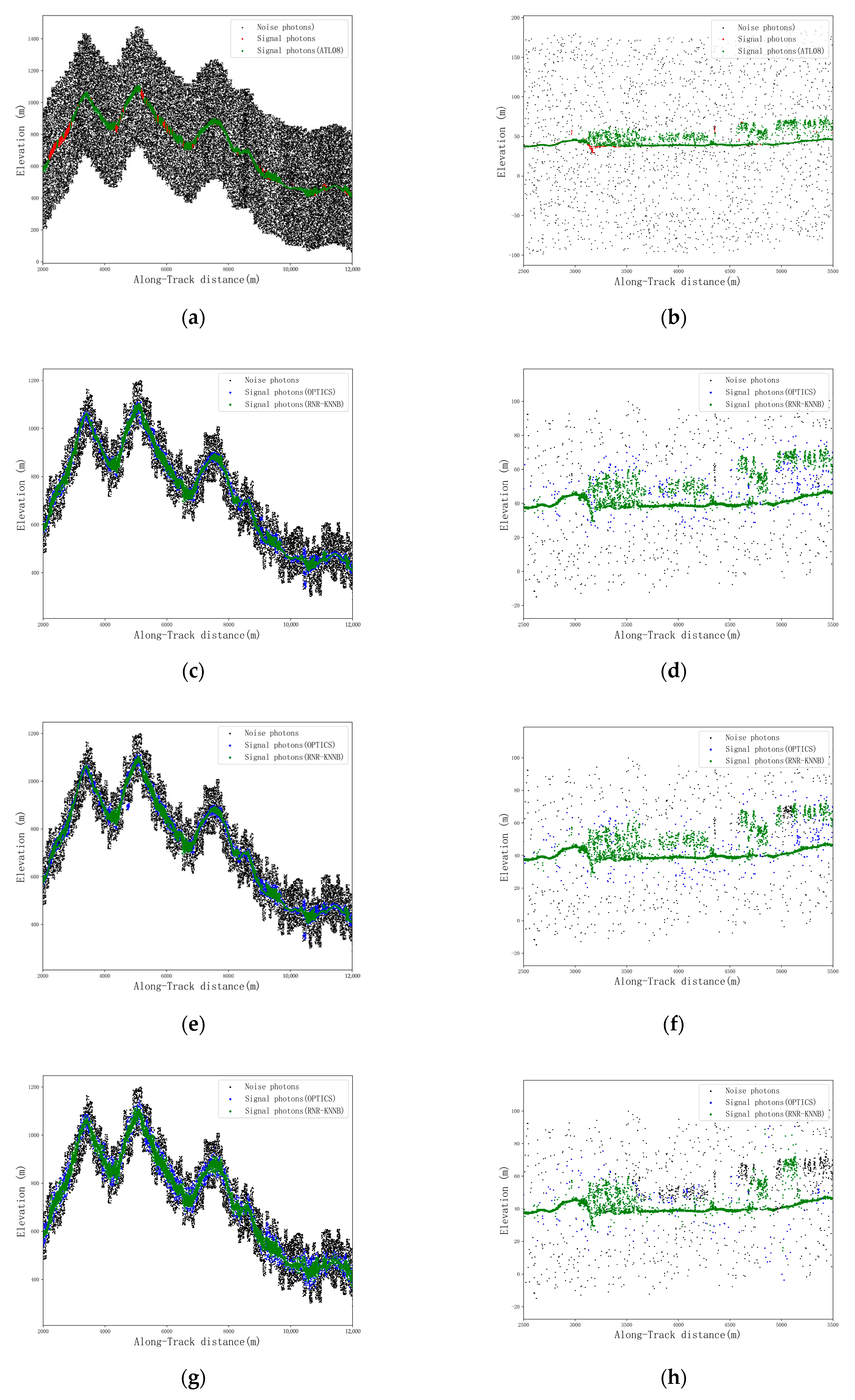
The multilevel filtering algorithm proposed in this study is capable of achieving the precise denoising of the ICESat-2/ATLAS daytime photon cloud data, and its overall accuracy and adaptability are also superior to those of the ATL08 algorithm.
(2)
In the case of the daytime strong beam, the multilevel filtering algorithm in the three filtering directions proposed in this study is capable of achieving more accurate denoising results, and the denoising accuracy is much higher than that of the ATL08 algorithm. Furthermore, the filtering direction does not exhibit any obvious impact on the denoising results of the multilevel filtering algorithm.
(3)
In the case of the daytime weak beam, the accuracy of the denoising results obtained through the multilevel filtering algorithm in the horizontal direction and the intra-group unified direction is similar and superior to the denoising results of the multilevel filtering algorithm in adaptive directions for each photon as well as the ATL08 algorithm. Therefore, in future relevant research, it is not recommended to use the multilevel filtering algorithm with adaptive directions for each photon in order to denoise the ICESat-2/ATLAS daytime weak beam photon cloud data.
(4)
SNR is an important factor affecting the denoising results of algorithms. The higher the SNR, the better the data quality, and denoising algorithms can also achieve better denoising results. For strong and weak beams, the p-value and F-value of the denoising results of multilevel filtering algorithms in three different filtering directions increase with the increase of SNR value.
Although the multilevel filtering algorithm proposed in this study is capable of effectively achieving the precise denoising of daytime photon cloud data with high background noise, the three different filtering directions affect the denoising results of strong and weak beam photon cloud data in different ways. The results of this study can provide reliable technical and methodological guidance for the denoising of ICESat-2/ATLAS photon cloud data in most cases. However, due to the continuous increase of forest canopy density and the complexity of the terrain in the study area, the denoising accuracy of the algorithm may decline to a certain extent. Accordingly, in the future, optical stereo images, such as GF-7 stereo images, and 3D terrain data should be used together in order to produce a denoising algorithm with higher precision and stronger applicability for further improving the denoising accuracy of ICESat-2/ATLAS photon cloud data under complex terrain conditions.

Author Contributions

Conceptualization: H.Y. and X.S.; data curation: Y.L., P.L. and J.C.; formal analysis: Y.L. and Z.Q.; methodology: H.Y. and Z.Q.; supervision: H.Y. and X.S.; validation: P.L. and Z.Q.; writing—original draft: H.Y., Y.L. and Z.Q.; writing—review and editing: J.C. and X.S. All authors have read and agreed to the published version of the manuscript.

Funding

This study was supported by grants from the National Natural Science Foundation of China (42261063, 41901370), Guangxi Science and Technology Base and Talent Project (GuikeAD19110064), Guangxi Natural Science Foundation (2018GXNSFBA28107), and the BaGuiScholars program of the provincial government of Guangxi (Hongchang He).

Data Availability Statement

Not applicable.

Acknowledgments

We acknowledge NEON and ESDS for providing airborne LiDAR data and ICESat-2/ATLAS data, publicly available at the NEON data portal (https://data.neonscience.org/data-products/explore, accessed on 1 May 2022), and NASA for providing the ICESat-2 data, publicly accessible at ESDS (https://search.earthdata.nasa.gov/, accessed on 1 May 2022).

Conflicts of Interest

The authors declare no conflict of interest.

References

  1. Zhu, X.; Nie, S.; Wang, C.; Xi, X.; Wang, J.; Li, D.; Zhou, H. A noise removal algorithm based on OPTICS for photon-counting LiDAR data. IEEE Geosci. Remote Sens. Lett. 2020, 18, 1471–1475. [Google Scholar] [CrossRef]
  2. Ranson, K.J.; Sun, G.; Kovacs, K.; Kharuk, V.I. Landcover attributes from ICESat GLAS data in central Siberia. In Proceedings of the 2004 IEEE International Geoscience and Remote Sensing Symposium, Anchorage, AK, USA, 20–24 September 2004; pp. 753–756. [Google Scholar]
  3. Wang, Y.; Ni, W.; Sun, G.; Chi, H.; Zhang, Z.; Guo, Z. Slope-adaptive waveform metrics of large footprint lidar for estimation of forest aboveground biomass. Remote Sens. Environ. 2019, 224, 386–400. [Google Scholar] [CrossRef]
  4. Pitkänen, T.P.; Raumonen, P.; Kangas, A. Measuring stem diameters with TLS in boreal forests by complementary fitting procedure. ISPRS J. Photogramm. Remote Sens. 2019, 147, 294–306. [Google Scholar] [CrossRef]
  5. Vernimmen, R.; Hooijer, A.; Pronk, M. New ICESat-2 satellite LiDAR data allow first global lowland DTM suitable for accurate coastal flood risk assessment. Remote Sens. 2020, 12, 2827. [Google Scholar] [CrossRef]
  6. Xia, S.; Wang, C.; Xi, X.; Luo, S.; Zeng, H. Point cloud filtering and tree height estimation using airborne experiment data of ICESat-2. J. Remote Sens 2014, 18, 1199–1207. [Google Scholar]
  7. Bincai, C.; Yong, F.; Zhenzhi, J.; Li, G.; Haiyan, H. Implementation and accuracy evaluation of ICESat-2 ATL08 denoising algorithms. Bull. Surv. Mapp. 2020, 25, 25. [Google Scholar]
  8. Popescu, S.; Zhou, T.; Nelson, R.; Neuenschwander, A.; Sheridan, R.; Narine, L.; Walsh, K. Photon counting LiDAR: An adaptive ground and canopy height retrieval algorithm for ICESat-2 data. Remote Sens. Environ. 2018, 208, 154–170. [Google Scholar] [CrossRef]
  9. Herzfeld, U.C.; McDonald, B.W.; Wallin, B.F.; Neumann, T.A.; Markus, T.; Brenner, A.; Field, C. Algorithm for detection of ground and canopy cover in micropulse photon-counting lidar altimeter data in preparation for the ICESat-2 mission. IEEE Trans. Geosci. Remote Sens. 2013, 52, 2109–2125. [Google Scholar] [CrossRef]
  10. Wang, Y.; Li, S.; Tian, X.; Zhang, Z.; Zhang, W. An adaptive directional model for estimating vegetation canopy height using space-borne photon counting laser altimetry data. J. Infrared Millim. Waves 2020, 39, 363–371. [Google Scholar]
  11. Milstein, A.B.; Jiang, L.A.; Luu, J.X.; Hines, E.L.; Schultz, K.I. Acquisition algorithm for direct-detection ladars with Geiger-mode avalanche photodiodes. Appl. Opt. 2008, 47, 296–311. [Google Scholar] [CrossRef]
  12. Lu, D.; Li, D.; Zhu, X.; Nie, S.; Zhou, G.; Zhang, X.; Yang, C. Denoising and Classification of ICESat-2 Photon Point Cloud based on Convolutional Neural Network. J. Geol. Inf. Sci. 2021, 23, 2086–2095. [Google Scholar]
  13. Zhu, X. Forest Height Retrieval of China with a Resolution of 30 m Using ICESat-2 and GEDI Data; University of the Chinese Academy of Sciences: Beijing, China, 2021. [Google Scholar]
  14. Magruder, L.A.; Wharton, M.E., III; Stout, K.D.; Neuenschwander, A.L. Noise Filtering Techniques for Photon-Counting Ladar Data. In Laser Radar Technology and Applications XVII; SPIE: Bellingham, WA, USA, 2012; pp. 237–245. [Google Scholar]
  15. Zhang, X.; Wang, L.; Li, J.; Han, W.; Fan, R.; Wang, S. Satellite-derived sediment distribution mapping using ICESat-2 and SuperDove. ISPRS J. Photogramm. Remote Sens. 2023, 202, 545–564. [Google Scholar] [CrossRef]
  16. Huang, J.; Xing, Y.; You, H.; Qin, L.; Tian, J.; Ma, J. Particle swarm optimization-based noise filtering algorithm for photon cloud data in forest area. Remote Sens. 2019, 11, 980. [Google Scholar] [CrossRef]
  17. Li, Y.; Fu, H.; Zhu, J.; Wang, C. A filtering method for ICESat-2 photon point cloud data based on relative neighboring relationship and local weighted distance statistics. IEEE Geosci. Remote Sens. Lett. 2020, 18, 1891–1895. [Google Scholar] [CrossRef]
  18. Zhu, X.; Nie, S.; Wang, C.; Xi, X.; Hu, Z. A ground elevation and vegetation height retrieval algorithm using micro-pulse photon-counting lidar data. Remote Sens. 2018, 10, 1962. [Google Scholar] [CrossRef]
  19. Huang, J. Study on canopy height estimation based on ICESat-2/ATLAS photon-counting LiDAR data. J. Northeast For. Univ. 2021, 73, 271–276. [Google Scholar]
  20. Huang, X.; Cheng, F.; Wang, J.; Duan, P.; Wang, J. Forest Canopy Height Extraction Method Based on ICESat-2/ATLAS Data. IEEE Trans. Geosci. Remote Sens. 2023, 61, 1–14. [Google Scholar] [CrossRef]
  21. Neuenschwander, A.L.; Magruder, L.A. Canopy and terrain height retrievals with ICESat-2: A first look. Remote Sens. 2019, 11, 1721. [Google Scholar] [CrossRef]
  22. Yanqiu, X.; Lei, Q. Accuracy of photon cloud noise filtering algorithm in forest area under weak beam conditions. Trans. Chin. Soc. Agric. Mach. 2020, 51, 164–172. [Google Scholar]
  23. Neuenschwander, A.; Pitts, K.; Jelley, B.; Robbins, J.; Markel, J.; Popescu, S.; Nelson, R.; Harding, D.; Pederson, D.; Klotz, B. Ice, Cloud, and Land Elevation Satellite 2 (ICESat-2) Algorithm Theoretical Basis Document (ATBD) for Land-Vegetation Along-Track Products (ATL08); NASA: Washington, DC, USA, 2019.
  24. Carrasco, L.; Giam, X.; Papeş, M.; Sheldon, K.S. Metrics of lidar-derived 3D vegetation structure reveal contrasting effects of horizontal and vertical forest heterogeneity on bird species richness. Remote Sens. 2019, 11, 743. [Google Scholar] [CrossRef]
  25. Wang, Y. Signal Processing on Spaceborne Photon Counting Laser Point Cloud and its Applications in Vegetation Remote Sensing. Wuhan Univ. 2020, 3. [Google Scholar] [CrossRef]
  26. Huang, J.; Xing, Y.; Shuai, Y.; Zhu, H. A Novel Noise Filtering Evaluation Criterion of ICESat-2 Signal Photon Data in Forest Environments. IEEE Geosci. Remote Sens. Lett. 2022, 19, 1–5. [Google Scholar] [CrossRef]
  27. Zhang, G.; Lian, W.; Li, S.; Cui, H.; Jing, M.; Chen, Z. A Self-Adaptive Denoising Algorithm Based on Genetic Algorithm for Photon-Counting Lidar Data. IEEE Geosci. Remote Sens. Lett. 2022, 19, 3067609. [Google Scholar] [CrossRef]
  28. Wang, Z.; Nie, S.; Xi, X.; Wang, C.; Lao, J.; Yang, Z. A methodological framework for specular return removal from photon-counting LiDAR data. Int. J. Appl. Earth Obs. Geoinf. 2023, 122, 103387. [Google Scholar] [CrossRef]
  29. Qin, L.; Xing, Y.; Huang, J.; Ma, J.; An, L. Adaptive denoising and classification algorithms for ICESat-2 airborne experimental photon cloud data of 2018. J. Remote Sens. 2020, 24, 1476–1487. [Google Scholar] [CrossRef]
  30. Lao, J.; Wang, C.; Nie, S.; Xi, X.; Long, H.; Feng, B.; Wang, Z. A new denoising method for photon-counting LiDAR data with different surface types and observation conditions. Int. J. Digit. Earth 2023, 16, 1551–1567. [Google Scholar] [CrossRef]
  31. Li, Y.; Fu, H.; Zhu, J.; Wang, L.; Zhao, R.; Wang, C. A Photon Cloud Filtering Method in Forested Areas Considering the Density Difference Between Canopy Photons and Ground Photons. IEEE Trans. Geosci. Remote Sens. 2023, 61, 3267823. [Google Scholar] [CrossRef]
  32. Zhang, J.; Kerekes, J. An adaptive density-based model for extracting surface returns from photon-counting laser altimeter data. IEEE Geosci. Remote Sens. Lett. 2014, 12, 726–730. [Google Scholar] [CrossRef]
  33. Meng, W.; Li, J.; Tang, Q.; Xu, W.; Dong, Z. ICESat-2 laser data denoising algorithm based on a back propagation neural network. Appl. Opt. 2022, 61, 8395–8404. [Google Scholar] [CrossRef] [PubMed]
  34. Li, Y.; Zhu, J.; Fu, H.; Gao, S.; Wang, C. Filtering Photon Cloud Data in Forested Areas Based on Elliptical Distance Parameters and Machine Learning Approach. Forests 2022, 13, 663. [Google Scholar] [CrossRef]
  35. Xie, F.; Yang, G.; Shu, R.; Li, M. An adaptive directional filter for photon counting Lidar point cloud data. J. Infrared Millim. Waves 2017, 36, 107–113. [Google Scholar]
  36. Gan, J.; Tao, Y. On the hardness and approximation of Euclidean DBSCAN. ACM Trans. Database Syst. TODS 2017, 42, 1–45. [Google Scholar] [CrossRef]
Figure 1. (a) Schematic diagram of the location of the study area (the background map is from Google EarthTM). (b) southwest of Washington State. (c) southwest of Georgia.
Remotesensing 15 04260 g001
Figure 2. The flowchart of the multilevel filtering algorithm.
Remotesensing 15 04260 g002
Figure 3. Schematic diagram of point cloud continuous direction angle calculation. (a) Three nearest neighbor points in three directions. (b) Three nearest neighbor points in the same quadrant. (c) Four nearest neighbor points, one in each of the four quadrants.
Remotesensing 15 04260 g003
Figure 4. Comparison of the rough denoising results with different number of iterations. (a) Strong beam. (b) Weak beam.
Remotesensing 15 04260 g004
Figure 5. Results of rough denoising. (a) Strong beam in study area 1. (b) Weak beam in study area 1. (c) Strong beam in study area 2. (d) Weak beam in study area 2.
Remotesensing 15 04260 g005aRemotesensing 15 04260 g005b
Figure 6. Fine denoising results of the strong beam. (a) Signal photon extraction results based on DTM and DSM data of airborne LiDAR, along with denoising results using the ATL08 algorithm in study area 1. (b) Signal photon extraction results based on DTM and DSM data of airborne LiDAR, along with denoising results using the ATL08 algorithm in study area 2. (c) Denoising results in the horizontal direction obtained through the OPTICS algorithm and the RNR−KNNB algorithm in study area 1. (d) Denoising results in the horizontal direction obtained through the OPTICS algorithm and the RNR−KNNB algorithm in study area 2. (e) Denoising results in the intra-group unified direction obtained through the OPTICS algorithm and the RNR−KNNB algorithm in study area 1. (f) Denoising results in the intra-group unified direction obtained through the OPTICS algorithm and the RNR−KNNB algorithm in study area 2. (g) Denoising results obtained through the OPTICS algorithm and the RNR−KNNB algorithm in study area 1, utilizing adaptive directions for each photon. (h) Denoising results obtained through the OPTICS algorithm and the RNR−KNNB algorithm in study area 2, utilizing adaptive directions for each photon.
Remotesensing 15 04260 g006
Figure 7. The denoising results of the strong beam with different algorithms in two study areas. (a) Study area 1. (b) Study area 2.
Remotesensing 15 04260 g007
Figure 8. Fine denoising results of the weak beam. (a) Signal photon extraction results based on DTM and DSM data of airborne LiDAR, along with denoising results using the ATL08 algorithm in study area 1. (b) Signal photon extraction results based on DTM and DSM data of airborne LiDAR, along with denoising results using the ATL08 algorithm in study area 2. (c) Denoising results in the horizontal direction obtained through the OPTICS algorithm, RNR−KNNB algorithm, and RANSAC algorithm in study area 1. (d) Denoising results in the horizontal direction obtained through the OPTICS algorithm, RNR−KNNB algorithm, and RANSAC algorithm in study area 2. (e) Denoising results in the intra-group unified direction obtained through the OPTICS algorithm, RNR−KNNB algorithm, and RANSAC algorithm in study area 1. (f) Denoising results in the intra-group unified direction obtained through the OPTICS algorithm, RNR−KNNB algorithm, and RANSAC algorithm in study area 2. (g) Denoising results obtained through the OPTICS algorithm, RNR−KNNB algorithm, and RANSAC algorithm in study area 1, utilizing adaptive directions for each photon. (h) Denoising results obtained through the OPTICS algorithm, RNR−KNNB algorithm, and RANSAC algorithm in study area 2, utilizing adaptive directions for each photon.
Remotesensing 15 04260 g008aRemotesensing 15 04260 g008b
Figure 9. The denoising results of the weak beam along with different algorithms in the two study areas. (a) Study area 1; (b) Study area 2.
Remotesensing 15 04260 g009
Figure 10. The denoising results of strong and weak beam photon cloud data in different directions and SNRs. (a) Weak beam denoising results in the horizontal direction. (b) Strong beam denoising results in the horizontal direction. (c) Weak beam denoising results in the intra-group unified direction. (d) Strong beam denoising results in the intra-group unified direction. (e) Weak beam denoising results in the adaptive direction for each photon. (f) Strong beam denoising results in the adaptive direction for each photon.
Remotesensing 15 04260 g010
Table 1. Detailed information of ICESat-2/ATLAS data used in this paper.
Study SiteICESat-2 DataGround Track
Study area 1ATL03_20210718232050_03871202_005_01.h5
ATL08_20210718232050_03871202_005_01.h5
GT1R (strong beam)
GT1L (weak beam)
Study area 2ATL03_20210515235947_07971102_005_01.h5
ATL08_20210515235947_07971102_005_01.h5
GT1R (strong beam)
GT1L (weak beam)
Table 2. Detailed information of airborne LiDAR data used in this paper.
Study SitePeriodAltitude (m)Slope (°)Average Canopy Height (m)
Study area 12021/07365–7080–24.2334
Study area 22021/0947–550–1.3227
Table 3. Accuracy evaluation results of rough denoising.
Accuracy Evaluation IndexStudy Area 1Study Area 2
Strong BeamWeak BeamStrong BeamWeak Beam
Rs1.001.001.001.00
Rn0.610.700.290.52
Table 4. Denoising accuracy of the strong beam data.
Filter DirectionAlgorithmAccuracy Evaluation Index
RsRnpF
Horizontal
direction
OPTICS0.990.600.510.67
RNR−KNNB0.970.650.540.69
Intra-group unified directionOPTICS0.990.610.510.67
RNR−KNNB0.960.650.540.68
Adaptive direction for each photonOPTICS0.990.600.500.65
RNR−KNNB0.980.630.520.67
-ATL080.850.670.520.65
Table 5. Statistics of weak beam denoising accuracy.
Filter DirectionAlgorithmAccuracy Evaluation Index
RsRnpF
Horizontal
direction
OPTICS0.970.800.470.63
RNR−KNNB0.920.870.550.68
RANSAC0.920.880.570.69
Intra-group unified directionOPTICS0.970.790.460.62
RNR−KNNB0.920.870.550.68
RANSAC0.920.870.560.69
Adaptive direction for each photonOPTICS0.950.750.410.55
RNR−KNNB0.940.800.450.59
RANSAC0.940.840.510.65
-ATL080.880.870.550.67
Disclaimer/Publisher’s Note: The statements, opinions and data contained in all publications are solely those of the individual author(s) and contributor(s) and not of MDPI and/or the editor(s). MDPI and/or the editor(s) disclaim responsibility for any injury to people or property resulting from any ideas, methods, instructions or products referred to in the content.

