
Failure of Threaded Connections: A Literature Review
by
 , , , , , and
Dario Croccolo
 ,
,
Massimiliano De Agostinis
*,
Stefano Fini
,
Mattia Mele
,
Giorgio Olmi
,
Chiara Scapecchi
and
Muhammad Hassaan Bin Tariq
Department of Industrial Engineering (DIN), University of Bologna, 40136 Bologna, Italy
*
Author to whom correspondence should be addressed.
Machines 2023, 11(2), 212; https://doi.org/10.3390/machines11020212
Submission received: 31 December 2022
/
Revised: 24 January 2023
/
Accepted: 26 January 2023
/
Published: 2 February 2023
(This article belongs to the Section Advanced Manufacturing)
Abstract
:Threaded fasteners are vastly used in the industry due to ease of mounting and dismounting and flexibility of design. Nonetheless, several researchers indicate that most failures recorded on nearly any kind of machinery and vehicles are initiated at fasteners. This review paper aims at summarising the failures involving threaded fasteners available in the literature. The analysis involves categorization of the failures according to the root cause, e.g., incorrect assembly, overload, fatigue, preload loss during operation, among others. The purpose of this review paper is to give a systematic glance of the topic to the scientific and technical community, to correctly orient future investigations on the broad topic of threaded fasteners.
1. Introduction
The joining of mechanical parts plays a key role in all industrial fields, such as aerospace, automotive, machine tools and others. The failure of a joining mechanism (permanent as well as non-permanent) can easily result in the failure of the whole machinery [1]. Threaded fasteners are one of the most widespread non-permanent joining techniques due to ease of assembly and removal [2]: unreliability of threaded fasteners can be a threat to the integrity of the whole structure. Failure of threaded fasteners can cause serious damages to the machinery, sometimes even resulting in catastrophic failures including personal injuries, apart from financial losses [3]. Numerous failures that have been reported were initiated at threaded fasteners. The 911 GT3 automobiles manufactured by Porsche were catching on fire, which led to Porsche recalling 785 cars for an engine replacement. The reason behind that event was the loosening of an engine bolt, which allowed oil to leak into the exhaust, where it ignited [4]. Similarly, in 2014 GM motors recalled 8.4 million cars because of problems including faulty fasteners [4]. Recently, Tesla Motors (Beijing, China) Co., Ltd. found a problem in the steering system of X series automobiles due to which they recalled more than three thousand cars produced from 2016 to 2020. The bolts joining the motor and housing of the steering system underwent corrosion when subjected to highly corrosive environments. This problem may arise in areas where chlorine salt (corrosive environment) is sprayed on the roads to remove the snow [5]. Thus, this number gives an idea of how minor negligence in bolts can result in huge financial and, sometimes, human losses because these failures can in turn lead to road accidents. Secondly, this problem does not involve only the automobile industry: for example, a failure of bolts in a lower marine riser package in the Gulf of Mexico resulted in leakages. After identification, 10,000 bolts were replaced which also resulted in disruption of activities for some duration. The bolt failure was attributed to hydrogen-induced stress corrosion cracking (HISCC) which was generated by an inadequate coating process [6]. Therefore, special consideration must be given to the several types of failure and a framework must be provided on how to tackle these various failures to update the bolt codes and standards, as well as the design procedures, in order to minimize the losses.
There can be several types of failures associated with threaded fasteners. Some types of failures can gradually and temporarily decrease the strength of the fasteners whereas others can lead the bolts to sudden breakage, causing severe damage to the entire system. Preload loss can occur due to several types of loadings on threaded fasteners. It can lead to the loosening of the joint, which can combine with fatigue in the case of vibrational loading to accelerate the failure [7]. Like loosening and fatigue, improper design parameters or inappropriate material processing can also cause similar fastener failures [8]. Stress corrosion cracking is the type of failure in which fasteners fail abruptly in a brittle manner. Therefore, prevention of these failures is crucial and only possible when the mechanism behind the failure is known. Researchers have put forth efforts in this regard by experimentally testing fasteners under different conditions and by setting up numerical as well as analytical models to predict their behaviour.
Considering the large amount of information regarding the failure of threaded joints available in the literature, the present contribution aims at systematizing the data in the framework of a classification based on the root cause of failure presented by each of the analysed papers and technical reports. In light of their research and industrial expertise on the topic, the authors deem this classification useful for both researchers and design engineers to understand the possible threats related to the application of threaded joints in their specific context, as well as to highlight possible areas of improvement of the knowledge on the topic, which might help to orient future research efforts.
2. Loosening and Preload Loss (Dynamic or Static)
Loosening is a process of rotation of the bolt in a direction opposite to the tightening. This can cause a loss of preload (tension created in the screw shank upon tightening) which can cause failures in the machinery [9]. For instance, Olmi [10] investigated the crack generated in a geartrain housing of an asphalt milling machine. The experimental simulation of the entire process with the assembly and the possible external loads showed that there was a stress increase due to the load hysteresis. The stress peak was present especially at the curvature where the crack originated. This load hysteresis was made possible due to the vibrational loading by the engine, which resulted in the self-loosening of the bolts. Therefore, he suggested design improvements along with the use of dampers to prevent the vibrational loading generated by the engine. Another preload loss due to dynamic loading and reported in the literature occurred in a pinion shaft for wheel loaders [10]. Croccolo et al. [11] investigated the fracture of the pinion shaft at its threaded end. A ring nut was used to preload the angular roller bearings. It was shown that the preload loss that took place under the nominal duty cycle is around 15 kN, due to which loosening starts occurring. This loosening results in the crack of the weakest portion of the assembly, i.e., the root of a sharp notch next to the threaded portion where the ring nut engages. The suggestion for maintaining the preload given was to use either an adhesive threadlocker or a mechanical locking device. Otherwise, the design of the assembly should be altered to lessen the amount of the loading, which includes using more compliant sleeves or even removing the inner sleeve [11].
Preload loss of threaded fasteners is also affected by the types of materials in use. For instance, Den Otter and Maljaars [12] reported that when stainless-steel bolts are used in aluminium-plated slip-resistant connections, significantly greater preload loss is observed as compared to the carbon steel bolts as specified in ISO 898-1. This preload loss is due to several reasons, among which viscoplastic behaviour, plate contraction and drop in the temperature are mentioned by the authors. The viscoplastic behaviour includes creep and relaxation phenomena. Therefore, it was suggested to use a higher safety factor (1.3–1.5 instead of 1.25 provided in EN 1999-1-1) depending on connection configuration to compensate for the increased preload loss due to material combination in the ultimate limit state [12]. It is worth remarking that a higher factor of safety determines an increase in the weight and cost of the engineering structure [13]. Therefore, if these aspects are crucial, the safety factor should be minimized by taking into account all the available information such as thread friction, rough surface finishing and the actual distance between the bolt axis and the edge of members [14].
Moreover, the initial preload application can also affect the loosening of the bolted connections. Bhattacharya et al. [15] studied the effects of initial preload application on M16 steel bolts that loosening is minimum when the initial preload is greater than or equal to 12 kN, as shown in Table 1. This might be due to the pronounced deformation of the points of contact with greater force values, which enable them to offer more friction [15].
2.1. Theories of Loosening Process
Various theories have been put forward to explain the process of loosening. The first theory on the rotation mechanism in bolts was coined by Sakai [16] in 1978. He reported that loosening occurs when the torque for bolt underhead slip is greater than the loosening torque for thread surface slip and lesser than the tightening torque required by the threaded portion. It was assumed in the theory that the nut is fixed; hence, the condition for loosening was based only on the torques on the bolt surfaces. In the classical theory used by Junker [17] (also known as the “complete slippage theory”), loosening is said to occur when frictional forces on the threaded surfaces are completely overcome. Yamamoto and Kasei [18] proposed a two-stage theory, where the first stage represents slippage on bolt-nut thread surfaces producing torsion on the bolt shank. In the second stage, the rotation of the bearing surface occurs on a moving plate, which results in a release of torsional deformation and produces loosening. In Junker’s theory, the bolt loosens first; however, in Yamamoto’s theory, the nut loosens first [18]. In contrast to the classical theory, Pai and Hess [19] proposed the “local slippage accumulation theory”. According to such a theory, complete slippage is not necessary to initiate loosening. Loosening starts when local areas of slippage accumulate together over the number of vibration cycles. Recently Li et al. [20] extended Sakai’s theory of self-loosening to include free nuts and free bolts under rotary vibrational loading, which agreed well with the experimental evidence. According to their theory, local slippage does not account for loosening, as opposed to the Pai and Hess theory. In Pai and Hess’s theory, the transverse load can introduce eccentricity, which in turn allows the piling up of local slippage. However, Li et al. [20] introduced a theory for rotational loading in which there is no eccentricity and hence does not allow accumulation of local slippage. These theories are summarised in Table 2.
2.2. Analytical Modelling
Loss of preload can occur with or without external excitation. This phenomenon of loss of preload has been studied from both standpoints in the past. Bretl and Cook [21] performed a static numerical analysis of the loading distribution over the threads during bolt tightening. Moreover, for the calculation of thread force, Miller et al. [22] established an equivalent spring model for fastening of the bolt and the nut. This approach is relatively simple and immediate. Miller’s model was later improved by Daadbin [23] by adding stiffness and damping, which he claimed to be influential factors for load transmission. Further investigation into the problem was performed by Daadbin and Chow [24], who examined the impact of the loading scheme on the preload loss. However, they neglected the deformation of the thread and modelled only one thread, because of which their model was unrealistic. Nevertheless, they concluded that the preload loss is less for the fine pitch, as it leads to a greater coefficient of friction and duration of applied force [24]. Moreover, an exponential expression for the stiffness of the members of bolted connections was developed using the numerical modelling by Wileman et al. [14]. Additionally, Chen et al. [1] made a significant improvement in Miller’s model by considering a multiple-thread system and adding the threads and bolt shank deformations. They modelled both the static and dynamic loading of the bolts and also determined if the bolt is exceeding the elastic limit by excessive initial preload. They calculated the effects of various aspects including the lead angle, material type, and external excitation parameters using the developed models. They concluded that a larger preload results in the extended service life of a bolted connection, whereas the trend is opposite for the lead angle of the threads and frequency of excitation force. They demonstrated the use of the model in the optimization of the design of a missile tail wing. Using the model, it was shown that preload loss, e.g., was decreased by decreasing the lead angle of the threads [1].
The various kind of loadings on the bolted joints can result in the loosening of the bolted joints. Work has been done to study the loosening process under different loading conditions such as axial, transverse, rotational vibration, impact loading and thermal loadings. These different types of loadings are discussed in the preceding sections.
2.3. Vibrational Loading
The majority of the vibrational loading on the threaded fasteners results in the loosening phenomenon. As an example, Casanova [25] studied the fracture of bolts joining the draft tube of a Francis turbine. The failure originated due to the presence of extremely high vibrational loading. The assembly failed in fatigue due to the loosening of the bolts connecting the draft tube with the lower flange. The preload loss characteristics of bolts must be increased, or the lower assembly should be designed such that preload loss is prevented in the bolts working under conditions of vibrational loading [25].
Housari and Nassar [26,27] developed a linear mathematical model to represent the self-loosening behaviour of bolts subjected to transverse vibrational excitation and validated it experimentally. Later, Yang and Nassar [28,29] developed more accurate, non-linear models for representing the bolt self-loosening subjected to transverse vibrational excitation. In their models, they considered the beam-bending equations to evaluate the bolt deflection and angle of rotation in a direction opposite to the tightening when it is subjected to external excitation. They considered a non-linear pressure distribution under the bolt head and on the thread surface, yet neglected the effect of nut threads [28,29]. Recently, Nassar and Yang [30] improved the same mathematical model to encompass the effect of the nut-thread geometry in the thread-friction analysis of the bolt–nut system, which came out to be in good agreement with the experimental results. However, analytical modelling still requires many parameters, such as the plasticity of the threads, to be taken into account for a realistic approach, which makes it much more computationally expensive [31]. Therefore, many researchers have studied the loosening response of bolted joints subjected to vibration experimentally as well as numerically.
Experimentally, Goodier and Sweeney [32] studied the axial vibrational loading in 1945 at Cornell University using microscopes to measure the nut rotations. Following their experimentation, different researchers improved their apparatus and studied the effects of various parameters on the loosening [33,34]. In 1969, an apparatus for the application of vibrational loading to the bolted connections was developed by Junker [17], which opened a new phase of research in the loosening of bolted connections. Junker used an eccentric mechanism to apply the vibrational loading to the bolted connection connections, the basic mechanism of which is shown in Figure 1.
His apparatus is still used by researchers with some modifications [27,35] and it also laid the foundations for current standardized testing of fasteners against vibrational loosening [36]. Another German engineer, Dinger [37], developed a more sophisticated machine for applying transverse and rotational vibrational excitations to bolted connections. Using his apparatus, the combined loading of translation and rotation can also be applied to the bolted connection. It has been found that self-loosening could occur below the critical kinematic parameters used in pure rotational or pure translational loading.
Dinger [38] also used a complete FEA model, whose working principle is shown in Figure 2, to replicate the bolt loosening phenomenon. He used the local slippage theory to find out the critical condition for the rotational loosening. The results of FEA were in agreement with the experimental analysis performed.
Chen et al. [39] performed FEA for studying the behaviour of the bolts subjected to transverse cyclic loading. The authors concluded from the simulations for tightening and loosening that a creep slip phenomenon is present, which permits the loosening of the bolt even with some of the stuck contact facets.
Moreover, in order to study the loosening response towards random vibration in PCB bolts, Du et al. [40] developed an experimental configuration to provide triaxial random vibrations using a triaxial vibrostand as shown in Figure 3. The base of the setup is fixed, denoted by position 5, and the PCB (position 4) is mounted on the base. Positions 3, 6, 7 and 8 correspond to triaxial accelerometers. Positions 2 and 9 are relevant to strain rosettes, and position 1 refers to the M10 UNC thread bolt. The authors also performed FE analyses for random vibrations and found a good agreement between the experimentation and the analysis. On the basis of their analysis, they proposed a three-stage criterium (stable, transition, loosen stages) for the self-loosening of the randomly vibrating specimen [40].
Table 3 enlists the various mathematical models as well as experimental techniques used to investigate the self-loosening phenomenon.
2.4. Impact Loading
Similarly, impact testing experimentation was performed initially by Baubles et al. [41]. They applied vibrations at excitation frequencies of 30 Hz and 60 Hz to the fixture, by means of a universal fatigue testing machine and electromagnetic shaker, respectively. Zhang et al. [42] developed an experimental apparatus to evaluate the effects of clamp length and loading direction of bolted joints on their self-loosening behaviour. The apparatus consists of a load cell for the measurement of clamp force, an angle transducer which measures the rotation of the screw tip, and an extensometer, which picks up the axial displacement of the joint. The line of action of the force was kept along the contact surfaces of the two plates in order to prevent any undesired bending moments coincident with the line of action of the screw force. Pin joints were used to attach the movable and fixed plates to the two jaws of the universal testing machine, which enabled easy force calculations.
2.5. Thermal Loading
Miller et al. [43] performed experimental and numerical investigation on bolts applied to a c-beam structure. They used a shaker with an amplifier for applying an external excitation to the c-beam structure. Eraliev et al. [44] developed an experimental setup to study the loosening behaviour of bolted connections under temperature changes. To study the phenomenon, they used two steel plates of 30 mm thickness. For preload change measurement, they used a washer-type compression load cell, while the temperature was monitored by means of a K-type thermocouple. A laser sensor was used to measure the movement of a thin plate attached to the nut, thus calculating the rotation of the nut. Heat cartridges as shown in Figure 4 were used to heat up the specimen. They found a direct proportionality between temperature increment and bolt preload loss, with preload being greater in the 1st cycle as compared to the remaining cycles.
All the examples above indicate that the phenomenon of loosening must be considered by engineers for designing a bolted connection with a particular focus on the type of loading, materials and temperature changes that can occur.
3. Incorrect Assembly
Improper assembly specifications, wrong execution or a combination of both often play a critical role in the failures of bolted connections. Casanova and Mantilla [45] showed that the application of an extremely low preload compared to the design specification (around 15% of the desired value, i.e., a coefficient of utilization of the screw ν = 0.64 w.r.t the yield point of the material, as reported by the authors) during the assembly process was a possible cause of failure in a bolted flange connecting a turbine with an alternator shaft. Such low preload levels, even in the absence of further loosening events—actually quite likely to happen under that condition—notoriously lead to increased load fluctuation on the screw for given external fatigue loads. This occurrence may easily lead the screw to fatigue failure, as documented by the authors [45]. Similarly, Fonte et al. [46] investigated the failure of bolts connected to a marine main engine. The reason for the final failure was fatigue, as shown by the fracture surface morphology. Nonetheless, the roots of the thread showed no corrosion or poor machining. The fatigue failure most probably occurred due to the application of a screw preload 20% lower than that prescribed in the assembly procedure [46]. Another failure due to an improper preload application procedure (plus poor design of the joint) was reported by Abdul-Jawwad et al. [47], who studied the failure of bolts attached to a heavy fuel oil meter. Fatigue failure took place at the thread runout of several bolts, at a sector of the flange of a pressure vessel made of two semi-spherical parts. The authors concluded that the failure originated due to an incorrect tightening procedure (the technicians probably did not follow well-established sequences, such as the star pattern). Such a wrong procedure led to the bending of some screws that, combined with the loads generated by the duty cycle, brought about fatigue failure of some bolts. The authors put forth a possible explanation for the wrong procedure adopted in the field, i.e., the difficulty for the technicians to reach some bolts of the assembly. On top of that, the joint was designed such that the thread runout coincided with the contact surface of the flanges, which is usually deprecated [48].
As a matter of fact, the process of bolt fastening to achieve the required preload may turn out to be all but straightforward. In bolted flanged joints, the amount of preload is affected by the surrounding bolts due to the elastic interaction of each bolt with the joining material. Due to this, in the pressure vessels and piping industry, special tightening sequences have been developed to achieve uniform initial preload on multi-bolted joints. One of those methods is the elastic interaction coefficient method introduced by Van Campen [49]. It was further developed by Bibel [50], according to whom interaction elastic coefficients are calculated from experimental data and are then used to calculate the final preload acting on the bolts. However, this method cannot be applied to non-linear systems. Nassar et al. [51] introduced another method, known as the inverse square method. In this method, all the bolts are fastened to the joint and then unfastened. During dismounting, the analysis of loads from the final to the initial loading state is done and the loads to be applied are measured. This method requires the initial unloading of all the bolts, which is one of its limitations [51]. Abasolo et al. [52] developed a metamodel for bolting sequences using the aforementioned methodologies. The optimization was done in Matlab at a very low computational cost, which could be used to optimize the bolts preload in one or two passes. Zheng et al. [53] developed another tightening sequence based on elastic interaction coefficient and gasket creep relaxation. The algorithm was used to reduce the dispersion of the clamping force. The dispersion of clamping force was demonstrated to drop when two passes were applied using the proposed algorithm with the nut factor from the first pass as an input.
As a final remark, multi-bolted joints are characterized by additional challenges with respect to single bolt joints: due to that, the tightening sequence plays a key role in the achievement of a correct initial force on each bolt. Without the correct sequence, the achieved initial preload would diverge from the required value, eventually leading to the failure of the joint as documented by the papers cited above.
4. Improper Design Parameters
The design of different bolt features such as thread surfaces, thread root radii and underhead bearing surfaces must be considered carefully. The design of bolted joints must also consider the number of bolts for various loading conditions of the application and the required initial preload for the service life. Sharp corners between the head and shank and at the thread root can be a source of high-stress concentration, which can lead to failure; hence, they must be minimized. Shiba et al. [54] assessed a Hoffmann–Vidal external fixation apparatus subjected to fatigue loading. The fatigue failure occurred at the point where the post diameter was reduced to fit into the pin bracket, which was a region of high stress concentration due to the change in diameter. It was not possible in this case to change the material of the apparatus. The appropriate design suggestion, therefore, was to press-fit the post into the pin bracket without a reduction in the diameter to avoid the stress concentrations at that point.
Similarly, Milan et al. [3] reported the failure of steel bolts used in speed reducer housings after a few hours of service. They performed metallurgical and mechanical analyses of the failed specimen. The root-cause of failure turned out to be the non-uniformity of the roots of the threads, which resulted in high stress concentration; moreover, surface defects and low toughness of the material contributed to the final failure of the bolts [3]. Curtis [55] analysed the failure of the joint between an impeller blade and the rotating assembly. The possible reasons for the failure included the sharp radius at the head-to-shank transition, the sharp thread root radius and an inaccurate application of preload. Additionally, the bolt thread shape was non-standardized, which must have resulted in the incomplete fitting of the male and female threads and hence led to the occurrence of fretting, as indicated by the microscopic images.
All the above poor design considerations led to crack initiation and failure of the bolted connection. The authors put forward some suggestions to prevent the failure, including (i) adopting rolled threads to obtain an additional compressive stress layer, (ii) improving the accuracy of the tightening torque measurement to avoid overtightening of the bolts, (iii) using bolts with a larger head-to-shank radius, and (iv) adopting rounded thread roots and standardized thread shapes to provide an improved matching between the thread geometries [55].
Moreover, the thread shape of the fasteners affects the stress distribution during assembly and service. Eraslan and İnan [56] studied the effects of the thread shape of titanium screw implants in the bone environment. They studied the four thread shapes including V thread, buttress, reverse buttress, and square threads. The von Mises stress distribution was similar for all the thread types. However, the distribution of compressive stresses was different. The maximum value of compressive stresses was 18 MPa in all the thread shapes. Reverse buttress thread had the maximum intensity area covered by the compressive stresses compared to the other thread types [56]. Similarly, Alemayehu and Jeng [57] investigated the stress distribution of dental implants having titanium grade 4. They found that the employment of different thread shapes resulted in different stress distributions in the fasteners. Maximum von Mises stresses occurring in the implant region of the prosthesis for the static and dynamic loading are shown in Table 4. It can be seen clearly from the table that stress distribution changes significantly by changing the thread shape. Under dynamic loading, triangular threads have almost 68% more maximum von Mises stress than square threads.
Similarly, the friction coefficients of the bolts and their lubrication state must be given due consideration while designing the joints. Stevenson et al. [58] reported the changes in frictional characteristics of the bolts during retightening to be a potential cause of failure of the bolts in a commercial jetliner. As recalled by the standards [59], slight changes in the friction coefficients can result in a significant change in preload for given tightening torque. Furthermore, during metallurgical and mechanical property evaluation, no material deficiency was found which could lead to failure. Hence, the authors suggested periodic replacement of the fasteners with new ones after being used. Moreover, when the materials of the bolts or nuts are changed, the value of the friction coefficients change, hence affecting the design of the bolts drastically. Likewise, Croccolo et al. [60] performed the failure analysis of bolted joints comprising aluminium alloy components used in front motorbike suspensions and studied the friction coefficients of various process parameters of the parts. The difference in friction coefficients indicated that applied torque must be matched to the process by which the parts are treated (e.g., spray painting vs. anodization). Moreover, it was suggested that during maintenance, with an increasing number of tightenings, the tightening torque should be adjusted to obtain the same amount of preload force [60]. Croccolo et al. [61] also studied the behaviour of titanium bolts with aluminium underhead bushings and steel nuts. They measured the torque and the friction coefficients for twenty retightening cycles on dry bolts and also used different lubricants (Teflon-added oil and ceramic paste). They reported that suitable lubrication is required when using titanium fasteners in combination with aluminium parts in order to achieve the desired level of preload and good stability thereof over repeated tightenings. Among the two lubrications, the ceramic paste showed a better performance in terms of stability of the preload (i.e., friction coefficients) over repeated tightenings, by protecting the contact surfaces from excessive wear. As a general statement, the use of proper lubrication is necessary for achieving the correct preload during repeated tightenings [61]. De Agostinis et al. [62] studied the friction coefficient in various tightening and retightening cycles of bolts, involving high-strength grade bolts (12.9) in combination with cast iron parts. After the fifth retightening, the value of the mean friction coefficient for the dry surface displayed greater variation as compared to the case of lubrication by ceramic paste. Moreover, the surfaces of the bolts deteriorated less with the application of ceramic paste, as shown in Figure 5. Han et al. [63] addressed the issue of thread galling in bolted joints through lubrication. They employed zinc oxide (ZnO) nanofluids for eliminating the problem of thread galling in threaded fasteners. However, the problem of agglomeration of nanofluids needs to be addressed by using different surfactants to enable them to be used in bolt threads to prevent excessive wear [63]. Kumar et al. [64] addressed the effects of storage conditions on the frictional characteristics of bolted joints. They investigated four Zn-flake coated threaded fasteners under cold (1 day, −20 °C) as well as hot and humid conditions (2–30 days, 40 °C, 95% RH). They showed a reduction in the friction coefficients down to half of the initial value. In cold environments, this reduction could be attributed to the presence of free water, providing lubrication to the underhead and thread surfaces. In hot/humid conditions, the reason for friction reduction might be the formation of zinc oxides. Among the two, cold storage turned out to be the most critical one, reducing the torque to even one-third compared to the tightening of the reference parts (no ageing) at the same preload level. In light of the above, the frictional behaviour of the joint must be given full consideration in the design phase: the state of lubrication, as well as the nature of the coating applied to the fasteners, are of paramount importance in the definition of the torque-preload relationship. Therefore, the designer must also take the storage conditions, the number of expected re-tightenings and the environmental conditions in general into account when prescribing the tightening torque for a specific application.
One more important design parameter are the loading conditions acting during the service of the bolts. Rezvani et al. [65] studied the behaviour of angle bracket connections under several types of loading conditions which they encountered in wall-to-floor connections. For the uplift and in-plane shear loading conditions, a significant amount of plastic deformation occurred because the elastic limits of both the angle bracket and bolts were exceeded. In the out-of-plane tension, there was a splitting of cross-laminated timber (CLT) panels. Hence, incorrect knowledge of the loading carried by bolts during service can hamper the performance of the joint.
Additionally, when designing bolted connections, the assumptions in the theoretical models must be assessed with great care. Croccolo et al. [66] studied the behaviour of screw clamps in front motorbike suspensions. They showed that the theoretical model usually adopted by textbooks for the calculation of screw clamps (based on a simple beam model) cannot catch the effect of geometrical irregularities. Therefore, by leveraging numerical analyses they suggested adding some corrective parameters to the basic analytical models in order to improve the accuracy of calculation on such specific kinds of bolted connections [66].
When designing composite bolted joints, the ply orientation and number, type of matrix and other structural parameters of the parts to be joined change the behaviour of the joint under the loading conditions. Researchers have carried out parametric studies on composite bolted joints and developed different failure criteria [67,68,69,70]. Among the various possible failure modes, bearing failure is the phenomenon in which bolted joints are designed to fail because of their progressive (thus, predictable) nature. Simplifying the problem, many authors consider the bolted composite joint as a pin joint, neglecting stresses other than in-plane stresses. Chang–Chang and Chang–Lessard formulations are among the criteria for bolted composite joints [71,72]. Moreover, non-linear shear stress–strain formulations have been applied in the past [73]. A more realistic picture of the phenomenon can be represented by a 3D formulation which takes into account the 3D bearing failure in a more sophisticated manner [74]. Moreover, out-of-plane stresses have been considered by Hashin [75] to present a criterion for failure which has been applied by researchers in bolted composite joints. Olmedo and Santiuste [76] presented a three-dimensional failure criterion considering the out-of-plane stresses and non-linear shear stress–strain relationship based on Chang–Chang and Chang–Lessard criteria. Finally, the hole diameter is important in the definition of the strength of bolted composite joints. There are several methods to determine the critical hole diameter, such as the method of progressive failure, characteristic length or failure envelope method [77,78,79]. Among these, the failure envelope method is cost-effective and timesaving, making it very appealing for real applications. In the failure envelope method, it is assumed that failure strength and stress concentration factor at the hole plate are linearly related to each other. This method was proposed by Hart-Smith and gained popularity because it made it easy to predict the bearing and tensile failure of double-lap joints having multiple bolts and quasi-isotropic lay-up [79]. This method is also adopted by ASTM D 7248/D 7248M-08 standard [80]. In 2013, Liu et al. [81] proposed a modified failure envelope method, which considered the effect of by-pass load on the bearing failure contrary to the conventional. The proposed approach was applied to two-bolt and four-bolt double-lap joints with a quasi-isotropic layout to predict failure. The predicted failure was in good agreement with the experiments. Moreover, this method can reduce the risk of tensile loading failure which is not considered by the conventional method. Cheng et al. [82] used the failure envelope method for two- and three-bolted joints. They concluded that the failure envelope method was neglecting the composite damage effect. In order to address this problem, they proposed another method to predict failure more accurately. On the contrary, the Monte Carlo method is also used by researchers because of its accuracy, but it requires numerous samples [83,84]. Liu et al. used the failure envelope method, Monte Carlo simulation and spring-based method to propose a new method which covered the drawback of inaccuracy and required few samples [85].
5. Material Properties
Material properties affect the behaviour of bolted joints. Different types of materials are used to design threaded fasteners with different responses to the various loading conditions. Bolts are manufactured through various processes to ensure the required level of performance throughout their service life. Various treatments (specific to the bolt material) are performed to achieve the specified mechanical properties. Any deviations from the specific process may generate undesired characteristics, which may in turn lead to the failure of threaded fasteners. In addition, material defects also adversely affect the application of the threaded fasteners.
Firstly, an overview of the main materials used for bolted joints is given. Then, the main issues affecting threaded fasteners are covered in the following sections.
5.1. Type of Material
Different types of materials are used in the bolted joints specific to certain applications. The stress and deformation behaviour of these materials changes the overall quality of the bolted joints. Mostly, the bolts are made of steel alloys standardized in ISO 898-1 [86]. Lee et al. [87] studied the behaviour of high-carbon steel and demonstrated that the manufacturing process determines an increase in the tensile strength of the bolt if compared to the raw material. The stress–strain curves of the raw material and manufactured bolts, found by tensile testing on an Instron 5583 mechanical press, are shown in Figure 6.
Kodur et al. [88] studied the high-temperature behaviour of grade 8.8 high-strength bolts. The bolts M16 and M18 were made from a SAE 10B38 steel bar, whereas the M22 bolts were made from a SAE 10B21 steel bar. The residual stress–strain response during cooling is shown in Figure 7. The first set of bolts (M16 and M18) retain most of the strength and stress–strain response they have at room temperature when heated up to 500 °C, as is obvious from Figure 7a,b. However, the bolts (M22) of the second set retain their properties up to 400 °C, as shown in Figure 7c. In all cases, bolts reach the yield point and undergo plastic deformation before fracture.
Similarly, Hu et al. [89] investigated the material response of stainless-steel bolts, A2–70 and A4–70 (M20 × 120) when exposed to elevated temperatures. The tensile behaviour was measured for the unheated specimen as well as during the cooling of the heated specimen, as shown in Figure 8. It was observed that for the unheated specimen, A4–70 has almost the same ultimate tensile strength, but greater yield stress as compared to A2–70.
Ban et al. [90] tested grade 10.9 high-performance (HP) steel bolts. The material was developed to work adequately at high loads while providing resistance to fire as well as corrosion. They performed tensile testing on M20 and M22, as shown in Figure 9. Due to the presence of the martensitic structure, the elastic-to-plastic transition is smooth, as is visible in the stress–strain curves.
Fracture models were used by Cai et al. [91] to study the mechanical behaviour of ASTM A325 bolts and A572 Grade 50 steel. Their findings show a good agreement between experimental results and those obtained by FEA. The tensile comparison between the measured and calculated stress–strain curve of A325 bolts is shown in Figure 10.
Titanium has been used as a bolt material in many sectors due to its high strength-to-weight ratio, biocompatibility and high corrosion resistance. Li et al. [92] performed a comparative study between the titanium alloy (Ti6Al4V) and different steel bolts. Their findings suggest that the ultimate tensile strength of titanium bolts is comparable to that of stainless-steel bolts A4–80.
Aluminium also gives the advantage of weight reduction in machine frames. The mechanical performance of aluminium bolted joints was investigated by Adeoti et al. [93] by means of tensile testing. The stress–strain response of a high-strength 6082-T6 alloy is shown in Figure 11. Their findings show that the aluminium’s tensile strength is much lower than titanium or steel bolts, which determines a reduction in the performance of joints.
The different types of materials used in the literature are summarized in Table 5.
5.2. Nonconformity of the Material
Cui et al. [94] inspected the fracture of a Ti-6Al-4V bolt that was generated during the rolling process of the threads (see Figure 12).
During inspections, they found an excessive amount of oxygen, which is toxic for titanium alloy, in the vicinity of the fractured regions. This oxygen prevented the conversion from the alpha to beta phase by increasing the beta transition temperature and hindered the crystallization by increasing the crystallization temperature of the alloy. Therefore, a coarse alpha phase was produced before the thread-rolling process, resulting in poor ductility and resistance to cracking of the alloy [94]. For such a sensitive alloy, proper shielding should be provided during the heat treatment processes; otherwise, atmospheric oxygen can accumulate in the alloy. Similarly, Jha et al. [95] analysed a case of shear failure that occurred at the head–shank transition of a titanium alloy fastener used to join the flight spin motor to the subsystem. Scanning Electron Microscope (SEM) analysis indicated a crack at the thread root which supposedly propagated inwards and resulted in the separation of the bolt head from the shank (full-length thread). The bolt head is recommended to be manufactured using forging in the region of coexistence of the two phases, which is below 995 °C for the Ti-6Al-4V alloy. However, the Optical Microscope (OM) analysis showed that only the alpha phase existed in the vicinity of the fractured zone, which is indicative of the fact that processing was done above the recommended temperature. Moreover, the martensitic structure is not observed in the shank area, which indicates that operation of martensitic formation was not conducted properly. Furthermore, microscopic analysis of the flow lines at the head-shank transition region reveals the presence of a sharp notch, shown in Figure 13, which promotes fracture. In summary, a combination of improper material processing, both in terms of microstructure and geometry, led this bolt to failure.
Moreover, Gong et al. [96] investigated the fracture of TP321 stainless-steel anchor bolts in seawater booster pumps used in nuclear power plants. The corrosion, visible on the fracture surfaces of the bolts, was promoted by the presence of chlorine (visible in energy dispersive spectrometry (EDS) analysis). This chlorine was thought to be introduced into the material during the maintenance of the pump where some seawater could have been sprinkled onto the pumps. This resulted in the failure of the bolts through SSC, as visible by the morphology of cracks in the axial plane of the bolt, shown in Figure 14, obtained through scanning electron microscopy (SEM).
5.3. Material Texture
In the selection of threaded fasteners for a specific application, the texture of the fastener materials plays a significant role. The texture is affected by the different processes performed on the fasteners during manufacturing, such as annealing, tempering, cold working, etc. Grimmer et al. [97], who analysed the behaviour of different-sized threaded fasteners, highlighted a difference in the engineering stress–strain curve between smaller (S02 (NAS1351N00-4), S00(NAS1352NO2-6)) and larger fasteners (S04(NAS1352N04-8), S06(NAS1352N06-10), S4(NAS1352N4-24)) which was probably due to differences in the grain orientations. The technique used to determine the grain orientation was the EBSD mapping (Inverse Pole Figures). The grains are elongated with greater orientation in the <111> direction, indicating the cold working performed on the fastener, while it is equally distributed in the S02 fastener, indicating that, in the latter case, annealing was performed, which resulted in a distributed set of grain orientations. This greater number of slip directions allowed failure at higher levels of strain, which is in accordance with the engineering stress–engineering strain curve [97]. Similarly, Qi et al. [98] studied the manufacturing of Ti-6Al-4V fasteners used in aerospace and different applications due to their light weight and high strength. By paying close attention to the microstructure and grain orientation during different processes performed on the alloy, they were able to produce fasteners with a yield strength higher than that of those used in the literature. The analysis of texture after rolling and drawing showed a deformed alpha phase with and directions, as shown in Figure 15a. Then performing heading destroyed the continuous fibre texture, and solution treating and ageing (STA) transformed the grains into bimodal microstructures, as shown in Figure 15b. Hence, if the texture is not considered during the design phase of bolts, noticeable differences can be observed in the stress–strain behaviour of the parts [98].
5.4. Viscoplasticity
Viscoplasticity of materials shall be regarded as an additional issue when dealing with threaded fasteners, as it can lead to loss of preload. Different materials have different viscoplastic behaviours: German guideline VDI 2230 mentions that, even in the absence of external loads on the joint, there can be preload loss due to embedment, creep or stress relaxation. Steel and aluminium display different material responses, e.g., embedding is more pronounced in aluminium as compared to steel. Furthermore, due to a difference in the thermal expansion coefficient, the responses of different materials vary [59]. Den Otter and Maljaars [12] studied the application of stainless-steel bolts on aluminium plates. They observed the effects of viscoplasticity and temperature change on the preload loss of the mentioned bolts. Their investigation showed that there had been a significant loss of preload as compared to the case of carbon steel joint due to the embedment creep, creep of aluminium plate and the stress relaxation in stainless-steel bolts. Moreover, the temperature change studies showed that a temperature drop of 30 °C resulted in a preload loss of 5% in the joint. In addition, the testing of bolts with vibrational excitation showed a significant amount of preload loss due to lateral contraction. Therefore, a higher safety factor (partial coefficient) must be used to account for such pronounced preload losses [12].
5.5. Corrosion
Corrosion is another material-dependent phenomenon that might induce failure in threaded fasteners. Radouani et al. [99] performed numerical simulations on the corrosion effects of bolted joints comprising low-alloy steel bolts and carbon-alloy steel plates by parameters from an electrochemical bath of 1 M HCl solution. They showed that the corrosion rate is directly proportional to the size of the bolt and depends on the steel alloy. Moreover, for bolts which are in contact with water, such as those applied to turbines, a highly corrosion-resistant material must be selected [99]. Casanova and Mantilla [45] report the failure of bolts connecting a turbine to the shaft of the alternator. They found corrosion at the roots of some threads and regarded this occurrence as a possible reason for the failure they documented. As a matter of fact, corrosion enables fatigue cracks to grow even at comparatively low levels of stress. A possible solution to the problem is to change the material of the bolts to stainless steel to minimize corrosion [45]. Similarly, Zhang et al. [86] studied the risk of galvanic corrosion in ASTM A325 bolts (a material whose mechanical characteristics are comparable to that of 8.8 class screws according to [ISO 898-1] when coupled with plates made of a martensitic stainless-steel ASTM A1010. They found out that, in the case of heavy saline exposure, the galvanic corrosion rate of A325 bolts was significantly higher when used in combination with A1010 steel than when used with an A588 weathering steel. The study suggests that a reduction of the galvanic corrosion rate can be achieved by painting the plates at the sites of application of the bolts, thereby reducing the cathode-to-anode area ratio [100]. Furthermore, the lubricant type also affects the corrosion characteristics of bolted joints. In fact, aluminium connections can undergo corrosion due to some lubes, which limits the number of suitable lubricants [12].
5.6. Supplier
Another factor leading to bolt failure is the inadequate quality of bolts. Abid et al. [101] applied the same torque to M12 bolts from different suppliers. The torques required to achieve the required preload were the same for grade 8.8 and grade 10.9 bolts, whereas another stud from an unknown supplier yielded at a lower value of torque. The reason was attributed to the overload because of the unknown property class of that stud. Sometimes, the combination of overloading with other factors leads to the failure of bolted connections [101]. Lacalle et al. [102] reported the failure of a bolt in a scaffolding. The failure analysis of the bolt showed that the crack was generated inside the bolt due to some environmental factors, such as corrosion. After the crack generation, propagation was carried out by the overloading on the bolt, which eventually resulted in the failure of the bolt during the dismantling procedure.
6. Fretting Fatigue
Fretting fatigue is another phenomenon which can result in the failure of threaded fasteners. Fretting fatigue is generated in the presence of moving frictional contacts which promote the formation of micro cracks that, in turn, lead to macro cracking at stress concentration regions [103]. Such an issue has been a challenge for threaded fasteners in the past and, as of today, it is still a point of concern. Walker [104] reported that failures of aircraft occur through fretting at the points which are connected through bolts, pins and rivets. Among these, bolted joints are sites of particular concern. Sandifier [105] studied the fretting fatigue of aluminium lap joints and suggested design improvements to improve their fretting resistance. According to the assessment carried out by the authors, a material replacement was not feasible due to other design constraints. The most favourable approach was to deploy compressive residual stresses on the joint surface by shot peening to prevent crack growth, along with adhesive application on the contacting surfaces before the assembly of the joint to prevent fretting initiation [105]. Wagle and Kato [106] studied the fatigue behaviour of bolted joints used in combination with 2024-T3 aluminium plates. They studied the effect of increasing the initial torque from 0 (pin loading) to 8 Nm. They found that with increased applied torque, the fatigue life of the bolted joint increased up to a certain level. However, at much higher levels of tightening torque, the fretting fatigue started affecting the joints in the vicinity of the bolt hole. The authors also used ultrasonic waves to detect the fretting crack in the assembled position at 1.8 to 2.1 mm away from the bolt hole [106]. Chakherlou et al. [107] also studied the double-shear lap joint made by 2024-T3 aluminium alloy under fatigue conditions. The initial torques applied were 0.25, 2 and 4 Nm, as shown in the S–N curve reported in Figure 16. They reported that increasing the amount of applied torque led to an increase in fatigue life. However, below a certain level of external loading, failure occurs due to fretting fatigue. As a matter of fact, at about 10 kN of external loading, failure was due to fretting fatigue, whereas at 18 kN fretting was not observed. The reason is that load is transferred by the friction of the plates at a low level of excitation, preventing the bolt shank from coming into contact with the hole surface. Nonetheless, at elevated levels of excitation, both friction between the plates and the bolt shank transfer the load. Therefore, based on the outcomes of this study, attention must be paid to the fretting phenomenon, especially at low levels of excitation.
Significant efforts have been put into studying the fretting fatigue issue since the beginning of the 20th century [108]: as early as 1964, Ungar [109] used experimental techniques to find the rate of decay of joints’ structural responses to study the damping characteristics of riveted joints, which could be increased by loosening of rivets. He also found out that, upon loosening the rivets, fretting fatigue was induced on the joint. Rogers and Boothroyd used an experimental technique to produce the loops of fretting response (friction force vs displacement amplitude) for metal interfaces [110].
Eriten et al. [111] developed a new apparatus to measure the fretting-fatigue behaviour of bolted lap joints by compensating for the misalignment and the high-frequency operation with respect to previous setups [112,113,114]. The misalignment accuracy had been improved by using a high-accuracy internal sensor in the piezo translator (PZT) and a 3-axis load cell for force measurements. Moreover, the design of the apparatus allows service at high frequencies, so a high-frequency amplifier can be used with PZT to perform calculations up to 3–4 kHz. Using this apparatus, the fretting behaviour of single-bolt aluminium and steel joints was studied. The stiffness and energy dissipation from the obtained fretting loops was in agreement with the existing literature [115,116]. The energy dissipation was more pronounced in aluminium joints compared to steel. Moreover, the shakedown process was greater in aluminium with respect to the steel joint.
Mutoh and Jayaprakash [117,118] analysed the fretting failure of various steel alloys by means of a tangential stress range–compressive stress range (TSR-CSR) diagram. They developed a generalized TSR-CSR diagram using the normalized tensile and compressive stress ranges for various steel alloys, as shown in Figure 17. The meaning of the diagram can be explained as follows: each point is obtained by FE calculation of the compressive and tangential normalised stress ranges; then, if the point falls above the experimentally determined fretting fatigue limit line, the joint is subject to fretting fatigue failure. If the point falls below the line, the joint is safe. They assessed the diagram on several types of contact geometries, including bolted joints. This generalized diagram could then be used along with FEA to predict the behaviour of bolted joints under fretting fatigue conditions, limited to the case of steel components.
6.1. Experimental Analyses
Juoksukangas et al. [119] developed an experimental apparatus and modified it for measuring the fretting fatigue of bolted joints, as shown in Figure 18. The flat specimens to be connected by bolts are held at one end by the main clamping, whereas vibrational loading is applied at the free end, by means of an eccentric mechanism. At 30 mm away from the main clamping, a bolted joint is provided. Strain gauges are connected to the bolt as well as to the upper specimen to monitor the stresses and the forces acting on the system. The displacements are calculated using the Digital Image Correlation (DIC) technique. The results showed that fretting decreased the fatigue life when increasing the preload or the bulk stresses.
Jiménez-Peña et al. [120] studied the fretting-fatigue response of Single Lap Bolted Joints (SLBJ) made of S500MC steel (a low-alloy, high-strength steel with UTS ≈ 650 MPa). They applied tension–tension fatigue cycles on the joint by means of a universal testing machine. They also used FEA modelling to further study the phenomenon. Fretting fatigue turned out to be the dominating failure mode and it decreased with increasing the initial preload. The preload force tended to affect the size of the sticking region and the position of the stress concentration. Moreover, the authors applied different multiaxial criteria (SWT, Fatemi-Socie and others) to forecast the site of initiation of the fretting-fatigue crack: all of them agreed upon the same location of the initiation site, i.e., around the centreline of the specimen, at a certain distance from the hole edge [120]. Li et al. [121] used a piezoelectric actuator to provide controlled displacement, as explained in a previously analysed paper [111]. Nonetheless, they improved the apparatus by using one laser beam along with a specific combination of the prism. By using this, they were able to measure the relative displacements more accurately and at a comparatively low cost (some studies used two laser beams). Moreover, using a spring leaf, the motion of the moving contact surface was guided, hence giving more control over the motion. They measured the effect of bolt preload and excitation amplitude. The fretting hysteresis loops changed significantly in the case of changing bolt preload. An increase in bolt preload resulted in an increase in friction force and a decrease in sliding amplitude. The fretting hysteresis loops changed from elliptical to parallelogram by increasing the excitation amplitude [121]. Szlosarek and Kröger [122] found an interesting behaviour while evaluating the fatigue performance of M22 screws combined with 5 mm-thick steel sheets (S355MC). They found out that at lower preload levels (0–30 kN), failure of the bolted connection took place at the bolt hole, while for higher preloads (110 and 225 kN), the crack initiates at the pressure zone, indicating the presence of the fretting phenomenon.
6.2. Numerical Analyses
Over the years, many authors put forth procedures for estimating the fretting fatigue behaviour of bolted joints which make use of numerical methods. Ferjaoui et al. [123] used FEA coupled with continuum damage mechanics to estimate the number of cycles to crack initiation in double-lap bolted joints (DLBJ). Figure 19a shows the FEA setup used by Ferjaoui et al., along with the relevant boundary conditions. In the first load step, contact between the pairs was established where the translational degrees of freedom were restrained in Al plates’ left and right-hand sides. In the second load step, the axial stress was applied to the right-hand side by removing the constraints. The mesh element was 8-node linear (C3D8R) with finer mesh at the contacts of 0.1 mm, as shown in Figure 19b. The estimated crack initiation life is between 80% and 90% of the total experimental life for the partial slip condition, showing a good agreement between the combined analytical-numerical model and the experimental data [123]. Similarly, many researchers have tried to tackle this problem using different approaches, including finite element methods (FEM), boundary element methods (BEM), finite-discrete element methods (FDEM) and molecular dynamics (MD) [124,125,126,127]. Armand et al. [128] considered the effect of surface roughness on the fretting behaviour of assembled structures using a BEM-based contact solver. They used two different time scales and space scales. This procedure enabled them to decouple the contact and the dynamics model, which in turn made it possible to study surface roughness more closely. Li and Yang [129] also performed a numerical analysis of the bolted joints wherein they introduced the k parameter, which represents the ratio between the bolt pretension and the shear load, and used this parameter to investigate the fretting behaviour of the bolted joint. They determined experimentally that when k is unity, the fatigue behaviour of the joint is dominated by the stress concentration. On the contrary, when k increases, fretting becomes the dominating factor.
As a final remark, due to the complex nature of the fretting-fatigue phenomenon, it is paramount to leverage all the available design tools (FE, combined with experimentation and analytical calculations based on well-established multiaxial criteria) in order to correctly define the parameters of the joint, based on the specific boundary conditions.
7. Fatigue Failure
It is widely known that fatigue failure may take place when structural parts undergo cyclic loading [130]. Bolted connections are subjected to variable loadings that can be cyclic in nature in automobiles, aeroplanes as well as machinery in general. The mechanism of fatigue failure is usually regarded as a three-stage process. At first, the crack initiates in the material due to the presence of defects or at stress concentration sites, under the action of repeated loading and unloading sequences. The second stage involves the propagation of a dominant crack. The final stage consists of the full rupture of the part due to the fact that the remaining cross-section is no longer able to withstand the design loads. The presence of the crack can be due to different reasons, each pointing to a different mechanism [131,132,133]. The reasons for the formation of a crack in fatigue failure can be due to the geometry of bolted connections, the profile of the loading on the joint, material defects and less than required bolt preload, etc. Extensive research has been performed to find the relationship between these parameters and the fatigue life of the specimen.
As mentioned in the discussion of improper design parameters, the application of an appropriate preload through the initial torque is mandatory for the proper operation of bolted joints. It is well-known that the application of insufficient preload results in reduced fatigue life due to the comparatively higher stresses seen by the screw for given external axial loads [48]. In some cases, as documented above, the preload decreases during the loading cycles due to the transverse contraction of the plates, which affects the contact of the bolt and plates [134]: this occurrence is particularly relevant in the case of steel bolts applied to aluminium plates. Based on the aforementioned considerations, the fatigue strength of the preloaded joint is better than that of the non-preloaded joint, and increasing the amount of preloading usually determines an increase in the fatigue life of the joint for given boundary conditions [135,136]. Chakherlou et al. [137] performed fatigue testing of M5 × 0.8 hexagon head steel bolts which were preloaded at 0, 244, 3409 and 6818 N. In another study, Chakherlou et al. [107] performed testing on a bolted connection (hexagon head M6 × 1, class 10.9 bolts) comprising aluminium plates at the initial tightening torques of 0.25, 2 and 4 Nm. In both cases, they found that the fatigue strength of the bolted connections increased with increasing the amount of initial preload [107]. Esmaeili et al. [138,139] used FEA to understand the effect of different amounts of initial torques on the bolts (1, 2.5 and 5 Nm) and verified the models experimentally. The results showed that the increase of tightening torque increases the fatigue strength of the tested aluminium double-lap bolted joints [138,139]. Abazadeh [140] performed numerical simulations on single-lap bolted joints and validated them experimentally. He found out that at a remote stress level of 20 MPa (cyclic load amplitude), the increase in tightening torque from 0 to 5 Nm increased the fatigue life of the joint. In the same study, Abzadeh showed that for higher tightening torques of 5 to 8 Nm, the increase in tightening torque decreases the fatigue life of the joint. This decrease was attributed to the fretting behaviour of the joint, as confirmed by the crack being produced away from the hole [140].
Furthermore, the influence of the geometry of the bolted connections on fatigue life has also been investigated by many scholars. Munse et al. [141] investigated the influence of changing the grip length of 1 in. high tensile bolts from to in. (approx. 44 to 95 mm) and reported that there is no change in fatigue strength. The fatigue strength obtained for all the specimens was 18,000 psi at 2,000,000 cycles. Griza et al. [142] investigated the influence of bolt length in M24 × 3 bolt studs used in a gas compressor for assembling flanges to housing. The experimentation was performed on nine short bolts with a length of 120 mm and eight long bolts of 173 mm in length. A spread sleeve was used with the longer bolt studs. The authors’ findings indicated that the increase in the bolt length increases the fatigue life of the bolted connection. The increase in the length of the bolts from 120 to 173 mm increased the fatigue limit at 5 million cycles by 8.6%. However, this difference might be attributed to the introduction of spread sleeves in longer bolts, which increases the member’s stiffness and decreases the bolt stiffness [142].
Moreover, the profile of load application for fatigue behaviour must also be considered. The two parameters, namely stress range (difference between maximum and minimum stresses) and the stress ratio (ratio of minimum to maximum stress) are of paramount importance. For the stress range, it was shown by Chakherlou et al. [107] that the mechanism of failure is different for the cases of low (fretting failure) and high (fatigue failure) load ranges, as discussed above. As for the stress ratio, there exists an inverse relationship between the stress ratio and fatigue strength. Birkemoe et al. [143] observed that there is an increase in the value of fatigue life when the stress ratio is decreased. Similarly, Atzori et al. [144] made a statistical analysis of aluminium bolted joints and observed that a change in the stress ratio from 0 to −0.5 in bearing-type joints increased fatigue strength by 50%. Zhou et al. [145] investigated composite bolted joints subjected to fatigue loading. They developed a modified version of the S-N curve for their model, by considering the stress ratio and the ply angle. They also reported that for constant ply angle, the slope of the S-N curve increased by increasing the equivalent stress ratio. Therefore, also in composite bolted joints, the fatigue life decreases by increasing the stress ratio [145].
Furthermore, materials processing including surface treatments can affect the fatigue life of bolted connections. It has been studied that zinc coating through hot dip galvanizing can have an adverse effect on the fatigue strength of the bearing type in which bolts are in clearance holes [136]. However, if it is kept at a certain thickness, then the fatigue life is not affected [146]. The generation of a hole can be done through different processes including cold working and hot working. Eurocode 3 provides FAT classes for only the drilled holes where each class has different fatigue curves. However, Cicero et al. [147] found that the fatigue behaviour of bolted connections changes by altering the hole generation techniques. They compared drilling with three thermal hole-generation techniques including oxyfuel cutting, plasma and laser cutting. They reported that FAT90 can be used for both drilled as well as oxyfuel-cut holes. On the contrary, for holes generated through laser and plasma cutting, FAT63 must be used (applicable to <15 mm thickness) [147].
The use of threadlockers also affects the fatigue life of bolted connections. Dragoni [148] investigated the fatigue life of M10 steel studs (class 10.9) with and without threadlocker. Loctite 243 was used as a threadlocker in this study. Fatigue testing was performed on high (11 ± 10 kN) and low (8.8 ± 8 kN) levels of force. In both cases, the fatigue life was improved by the use of the threadlocker by a ratio of mean life being 3.5 for the high load range and 2 for the low load range [148].
Efforts have been made to study the fatigue behaviour of the bolted joints with respect to the geometry and design of bolted joints. Taylor and Pan [149] performed a numerical investigation to find out the stress and strain at the first thread of the joint by applying fatigue loading. Using these stresses and strains, the multiaxial fatigue theory and critical plane approach were employed to determine the failure location. For M14 metric threads with a 0.29 mm root radius, the failure was found to originate at 18° from the centerline of the thread root and inclined at 45° to the thread root surface. This methodology can be employed to find the failure location of other thread sizes [149]. Similarly, O’Brien and Metcalfe [48] investigated the high-stress concentration regions in fasteners which lead to fatigue failure of bolted joints. They inferred that work on reducing the stress concentration regions has been performed in the past but is seldom applied in the mass production of fasteners. They suggested using an elliptical shape for the underhead-shank transition to reduce stress concentration. The thread should be roll-formed to achieve a good shape of threads and to have residual compressive stresses. The nuts should be designed so as to minimize stress concentration at the first engaged thread, and there should be threads above and below the nut. Guide surfaces should be present with fitted fasteners with generous radii. Hareyama et al. [150] devised a method for analysing the working loads on the bolts by simulation of the actual machine environment. By this approach, the designer is able to predict the strength and durability of bolted joints. Strain gauges were used to monitor the strains on the bolts and analytical equations were proposed to convert these strains into loads. A stress history diagram was obtained from the experimentation. This diagram was then used to estimate the fatigue life of the connections.
Sorg et al. [151] proposed a local approach to predict the durability of bolted connections subjected to fatigue loading. The approach based on normal forces could not predict well the durability of the bolted connections subjected to fatigue loading. Hence, Schneider’s method was improved to predict the multi-axial, time-dependent problems of fatigue loading in screws. The presented method gives the values of damage in the first load-bearing thread of the screw over the circumference of the thread [151]. Finally, Nassar and Li [152] proposed another model for determining stresses in high-cycle fatigue. Using such a model, the S-N curves were constructed with the help of experimental data of ultra-high strength fasteners (grades 14.8, 15.8 and 16.8) and standard fasteners (grades 12.9 and 10.9). The normalized fatigue strength of UHS fasteners was then compared with that of standard fasteners.
8. Overload
Bolted connections are designed according to the loading conditions that might occur in the specific application. If the loads on the bolted connections exceed the limit, the bolted connections fail, resulting in detachment of the plates, fracture of the bolts, or both. In addition, if the initial torque of the bolts is increased beyond the design limitations, the bolts can also fail upon assembly [153]. Overloading of the joint is driven by many factors. One of the reasons is an incorrect application of lubricant on bolts. Eliaza et al. [154] investigated the failure of bolts in a helicopter main drive plate assembly. Their analysis showed that the incorrect application of Molykote lubricant spray, an anti-seize material, was the reason for failure. Due to that reason, the same value of torque resulted in axial force being 1.7 times higher than the required level. This was greater than the yield point of the bolt. As a result of this investigation, it was suggested to apply the anti-seize product only on the threads, thus explicitly excluding the underhead surface of the screw, in order to keep the total friction coefficient of the joint within the desired range [154]. The bolt failure analysis of Stevenson et al. [58] also showed that ductile overload was the reason for failure. This was due to a deviation in the frictional characteristics of the joints.
In some circumstances, bolts may fail through simple static overloading. Xue et al. [155] investigated the explosion of a reactor in which the bolts were seen fractured just after the explosion. The investigation revealed that the bolts and the pressure vessel met all the design parameters. Therefore, the only possibility of failure was overload in the pressure vessel which resulted in tensile overload in the bolts and led to the failure of the bolts and hence the reactor [155]. Moreover, Chen et al. [156] carried out an investigation into the failure of rock bolts in a coal mine. The main outcome of their study consisted of demonstrating that the failure of the majority of the analysed bolts was due to stress corrosion cracking, whereas one of the bolts was fractured due to simple overloading due to undesired bending stresses applied to the bolt [156]. Neidel et al. [157] reported that some bolts failed due to torsional overloading during the final assembly stage of a gas turbine engine. The reason for torsional overloading was attributed to the non-conformity of the assembly procedure.
9. Corrosion and Other Environmental Effects
Stress corrosion cracking (SCC) is regarded as a frequent root cause of failure in bolted joints. The presence of stresses, specific bolt materials and a corrosive environment are the factors that combine to bring about this failure mode, which is brittle in nature and usually results in catastrophic failure of the components, as it usually goes undetected prior to final rupture since it can take place in the presence of mildly corrosive environments [158]. It is a common type of failure in underground rock mines where the aforementioned conditions are easily fulfilled. In 2002, a study showed that most failures occurring in rock bolts were due to SCC [159]. Crosky et al. [160] performed a failure analysis on 44 bolts which failed in four different underground coal mines in Australia. Most of the bolts that they investigated were fractured due to stress corrosion cracking (SCC), as indicated by the discoloured region in the fracture surfaces. Moreover, the majority of the bolts showed bending, from which it can be estimated that bending stresses were the reason for initiating SCC [160]. Similarly, Escobar et al. [161] investigated the failure of a submersible pump system. The failure was attributed to the bolt which fractured due to SCC, as shown by the nucleation at the high-stress concentration and the presence of rust on the fracture surfaces. The fracture surface is shown in Figure 20 with an arrow pointing to the nucleation region, and the propagation region shows the presence of corrosion.
Craig et al. [162] investigated the failure of several rock bolts coming from two hundred mines located in Australia which were made from X-grade steel with a minor diameter of 21.7 mm. Of all the rock bolts, 70% had failed due to SCC, the rest of them failing from pitting corrosion at local sites. Chen et al. [156] also investigated the failure of six HSAC 840 steel rock bolts from underground coal mines which had failed from the end of the bolt in the threaded region. Failure of half of the bolts was initiated from the thread root, while for the other half the failure was due to cracks initiated as a result of bolt bending. Among the examined six bolts, five had failed due to SCC, as suggested by the presence of a 1.5–4.5 mm discoloured region at the origin of the fracture. The rock bolts usually used in Australian rock mines (M24-3.0 × 2400) were given 100–140 kN preloads in order to achieve a water-tight sealing, thus allowing water accumulation, which finally led to SCC [156]. Similarly, Neidel et al. [163] reported the failure of an M10 bolt in a gas turbine due to SCC. In this case, SCC was initiated by pitting corrosion as observed on the bolt. Moreover, tensile stresses might have been due to three possible reasons. Over-torquing could have been easily done for these bolts, as the designated torque was 30 Nm, a low value. Secondly, cold forming was evident from the microstructure, and thirdly, tack welding was performed to keep the bolt in place. Both of these phenomena induce residual tensile stresses which contributed to the phenomenon of SCC in the bolt [163]. Hagarova et al. [164] studied the cause of the failure of a brass bolt used to conduct direct current. The failure was on the last thread of the bolt, which was characterized by a lower zinc content. SCC was the most probable cause of failure, as indicated by the dezincification which is associated with this failure mode.
9.1. Theories of Stress Corrosion Cracking
Efforts had been made to study the underlying mechanisms of SCC. The most common mechanism is hydrogen embrittlement (HE) [165]. The main factor for hydrogen embrittlement is the presence of hydrogen atoms and a metal. This process reduces the ductility of the steel by introducing microcracks. The process is initiated by the diffusion of hydrogen atoms into the lattice of iron, which causes the lattice to inflate. When hydrogen becomes concentrated enough, cracks start developing. Various sources of hydrogen exist in the environment which can promote the process, such as water decomposition, the process of corrosion and by-products of H2S reaction with iron [166]. Recombination poisons, which are the adsorbents of hydrogen, control the hydrogen absorption rate. These recombination poisons act to prevent hydrogen from combining and forming molecules, hence promoting the diffusion of the hydrogen atoms into the iron lattice [167]. The vacancies created inside the steel by cold working are an easy target for hydrogen accumulation. The atomic hydrogen diffuses into these sites and accumulates, leading to the HE process [168]. Jha et al. [169] reported the failure of cadmium-plated 35NCD16 steel (heat-treatable steel with 0.32–0.39% C, min UTS = 1000 MPa, min Sp02 = 800 MPa) threaded fastener because of hydrogen embrittlement. The most probable reasons behind this occurrence of hydrogen embrittlement were: (i) spheroidization in an uncontrolled atmosphere, (ii) insufficient baking, and (iii) a cadmium-plating process which made hydrogen accumulation possible, plus (iv) residual stresses due to oil quenching [169]. Villalba and Atrens [170] carried out an experimental study to understand the underlying mechanism of SCC in rock bolts. They applied accelerated corrosion studies to distinct types of steel used for rock bolt manufacturing as well as commercial steel alloys. The locations where SCC was observed were at low pH (2.1) and had negative electrochemical potential. Under this condition cathodic reaction occurs, forming hydrogen, i.e., . Hence, they inferred that hydrogen embrittlement is the most probable cause of failure [170].
Other environmentally assisted degradation mechanisms studied in the literature comprise the so-called microbiologically influenced corrosion (MIC). In this type of SCC, anaerobic sulphate-reducing bacteria (SRB) perform sulphur oxidation or sulphate reduction to generate free sulphuric acids, which can act as a corrosive environment. They can also form highly corrosive biofilms which can affect the bolts. Moreover, the nitrate-reducing bacteria (NRB) were found to be a source of SCC in copper. NRB reduce nitrate into ammonia, which acts as a corrosive environment for copper alloys [171]. They develop biofilms, acting as corrosive environments at highly localized levels, which contain different pH values, oxygen and chemical species. The underground regions where rock bolts are used were found to contain these bacteria [172]. These bacteria, most importantly, produce hydrogen sulphide, which converts into ferric sulphide reacting with rust. Hydrogen sulphide also assists in hydrogen adsorption by acting as recombinant poison; hence, SRB also promotes hydrogen embrittlement [173].
9.2. Experimental Analyses
Several experimental strategies have been developed to examine stress corrosion cracking based on hydrogen embrittlement as well as microbiologically influenced corrosion. In 1993, Atrens et al. [174] introduced the use of an experimental apparatus for a linearly increasing stress test (LIST) method to test SCC. In this test, a load-controlled strategy is applied to assess the specimen against SCC. In the apparatus, the specimen is loaded at one end of a lever beam. The other end of the lever beam has a moveable load. This load can be moved away to increase the moment arm and increase the torque acting on the specimen. This test has been used by many researchers to assess the SCC on bolts [174]. Gamboa and Atrens [175] used the LIST apparatus to test various rock bolts, in which rock bolts failed in a similar manner to the service failure using LIST at a stress rate of 0.019 MPa·s−1. Villalba and Atrens [176] also used the LIST testing for testing rock bolts against SCC. They tested various bolts which failed at a stress rate of 0.019 MPa·s−1, whereas only five did not fail. Aziz et al. [177] developed an experimental apparatus to assess the rock bolts subjected to corrosion conditions with axial loadings of 100 and 200 kN. Water was dripping on the 520–540 mm length of bolts taken from Shoalhaven River inlets (NSW, Australia) with a pH of 3.4 to 4.3. The experiment was conducted for three and a half years and showed no initiation of SCC [177]. Vandermaat et al. [178] built a bending and torsion loading apparatus (BaTLa) to test SCC in rock bolts. They collected mine water from the locations where SSC failure had occurred. At the time of reporting, the three bolts did not show SSC after immersion in that environment from 6 months to 1 year [178].
Therefore, removing hydrogen and microorganisms could be regarded as an effective strategy to mitigate the onset of SCC.
10. Impact Loading
Bolted joints are often subjected to impact loading in different situations in several applications, such as construction [179], aerospace [180], etc. Therefore, the behaviour of bolted joints subjected to impact loading must be studied systematically. The influence of impact loading on threaded fasteners has been studied since 1964. At that time, Hongo [181] studied the effect of tensile impact on the threaded portion of the fasteners. In 1968, Koga [182] presented a theory for the mechanism of loosening due to impact loading and provided solutions according to his theory. He postulated that loosening would occur when compressive impact occurs on the thread surfaces. The dynamic loading on the nut thread must be kept greater than or equal to the dynamic loading on the bolt thread to prevent loosening. The theory was verified with the help of impact experimentation in which the fastener assembly was lifted to a desired height with the help of four sashcords. The impact states were measured using strains attached to the apparatus. The experimentation and hypothesis were in good agreement with each other [182]. Koga and Isono [183] presented a theoretical model based on self-loosening limit diagrams. Their theory considers the propagation of compressive and tensile waves when axial impact loading is applied. There is the repetition of stress waves reaching the free surface of the bolt, which causes the preload to drop, resulting in the loosening of the bolt [183]. Daadbin and Chow [24] presented a mass-spring model for studying different parameters affecting the loosening of bolted joints. Among these parameters, they studied the effect of impact loading on the joints, which showed that loosening would occur if the spring rebound caused by the impact is greater than the compression induced by the preload [24]. An analytical model was presented by Saleem and Nasir [184] for anchor steel bolts loaded by impact. They studied the effect of impact loading (for pull-out) on the bonding of the anchor steel bolts using the analytical model and verified it using impact loading imparted by a Schmidt hammer. The analytical approaches become overly complex for bolted joints subjected to impact loading, especially when more than one bolt is involved. For this purpose, researchers have worked to produce models which are less computationally intensive without much compromise on accuracy [184]. Moore et al. [185,186] proposed a reduced-order model (ROM) for this purpose and verified its accuracy by means of a split Hopkinson bar. The mathematical relationship between joint stiffness and fastener torque was developed which agreed with the experimental results. The model was able to predict the preload loss due to the impact loading of the bolted joints. For the impact velocity of 10.8 ms−1 and 54 Nm initial torque, the model predicted a preload loss of 61.1%, which was close to the experimentally found preload loss of 63% [185,186]. In another work, Saleem [187] presented a shear-lag material model for steel anchor bolts subjected to impact loading. The model considered the cracking at the interface caused by impact loading along with cyclic pull-out push-in response of bolts. Previous study gave only impact response of pull-out response of steel anchor bolts. However, both pull-out and push-in response (cyclic impact loading) is taken into this model, which could be used to simulate the response of the bolts. The stresses generated with respect to the displacement of impact loading are found and can be used to check the integrity of bolts as well as the bolt/concrete interface. The model was in agreement with the numerical simulation as well as experimental testing [187]. Cao et al. [188] presented a failure criterion for impact loading on bolted flange joints for aeroengines. They categorized the failure mechanisms of the bolted flange joints based on the yield or failure of the bolt or flange or both. The yield and failure modes were then estimated based on the relationship between the plastic resistances of the flange and the bolt. The experimental validation was performed with a smoothbore powder gun. It was used to impart impact to the joints at velocities of 90 to 220 ms−1, which was a representation of debris in a real situation in aero-engines. The failure modes predicted by the theoretical model were in agreement with the failure modes obtained through experimentation. Based on the criterion, different design improvements were suggested by using finite element modelling [188].
Over the years, both experimental and numerical approaches have been used to study the behaviour of bolted joints subjected to impact loading. Thin panels are joined using bolts in automobiles which might fail under impact loading due to high plastic strains induced. Simplified models were introduced which reduced the computational cost without compromising the accuracy and were verified with one full model. The models were giving accurate results with significant time savings in model processing [189]. Guo et al. [190] used the split Hopkinson pressure bar to study the force transmission in bolted flanged joints under impact loading. The results indicated that higher damping was achieved with greater values of excitation frequencies. Zheng et al. [191] performed an experimental study of loosening in threaded connections, still generating impact loadings by means of the Hopkinson bar. The schematic of the modified Hopkinson bar used in their study is shown in Figure 21. A high-speed camera was used to capture the loosening angle of the threaded connection subjected to impact loading. 3D finite element modelling was also performed considering the single shock wave. For single shock wave assumption, it is necessary to employ a boundary condition which prevents reflection of the shock wave. For this purpose, infinite element type (CIND8R in ABAQUS 6.14) was chosen, which enables the setting up of non-reflective boundaries. The Johnson–Cook model was utilized to simulate accurately the elevated strain-rate phenomenon. The results showed that loosening depends on initial preload as well as the amplitude of the stress wave, with every single wave contributing to the loosening, which accumulates to provide the final loosening.
Furthermore, Ngo et al. [192] studied the impact-loading behaviour of beam-column joints. They compared the behaviour of steel and GFRP bolts under impact loading using a pendulum system imparting the impact loading. A load cell captured the applied force, and the failure of the joint was detected by a high-speed camera, as shown in Figure 22. The GFRP bolts give the advantage of corrosion resistance compared to the steel joints as well as preventing the opening of material due to residual stresses. The impact loading showed shear failure for which more fibres can be applied in order to prevent failure in that direction.
11. Conclusions
Several types of failure modes characteristic of threaded fasteners have been reviewed. From the existing research, it can be deduced that self-loosening plays a crucial role in the failure of threaded connections. This phenomenon is attributable to different causes and requires adequate predictive modelling. Specifically, the literature review highlights the need for analytical modelling for rotational loosening as well as for local slippage accumulation in case of transverse excitation. Moreover, extensive research should be dedicated to investigating the role of material combinations in loosening.
The body of the literature shows that the uncertainty on the initial preload is the main cause of failure arising from the assembling phase. Particularly, the correct choice of the bolting sequence is essential for the correct application of the initial preload in case of multiple bolted joints. This fosters the development of new efficient algorithms to reduce the dispersion of the clamping force of multiple bolted joints.
Another key point emerging from this review is the need for a proper material choice depending on the specific application. This choice must consider the effects of the manufacturing process on the texture and microstructure of the material. Close attention must also be paid to the interaction between the material of the bolt and clamped parts. For example, differences in the coefficients of thermal expansion could result in the failure of bolted joints for small temperature variations. Future research direction might consider the development of new stiffer, lighter and corrosion-resistant bolt materials and their compatibility with innovative materials used for clamped parts.
The research on new bolt materials must include the development of TSR-CSR diagrams, which have been demonstrated to be a fundamental tool to assess fretting fatigue failures. The development of new coatings to reduce the risk of this kind of failure is another promising direction for future studies.
The reviewed studies highlighted several factors affecting the fatigue failure of bolted joints, such as the preload, geometry of the bolts, load spectrum, use of threadlockers and material processing techniques. Since threadlockers and lubricants have been demonstrated to significantly improve the fatigue life of bolted joints, new formulations should be investigated in the future. Another promising research direction is the design of new thread geometries to reduce the stress concentration and increase the lifespan of threaded fasteners.
It has also been discussed how the incorrect design of the bolted joints with respect to the applied loadings may lead to failures due to overloading. This phenomenon is also closely related to the frictional characteristics of the joints. Specifically, lubrication plays a key role in determining relations between applied torque and preload. In the future, the effects of anti-seize materials must be further investigated to clarify whether their application should be limited to the threaded portion or extended to the whole body of the bolts.
As far as environmental factors are concerned, the literature highlighted a predominant role of Stress Corrosion Cracking (SCC) in the failure of threaded joints. The main mechanisms of SCC include hydrogen embrittlement (HE) and microbiologically influenced corrosion (MIC). The presence of hydrogen must be monitored closely during the material manufacturing and the service of the bolted joints. To date, there is still very little knowledge about the MIC of threaded fasteners. The experimental investigation and analytical modelling of this phenomenon and its inhibitors are thus important issues for future research.
Many models have been proposed in the literature to explain the process of bolt failure due to impact loading. The main gap in this area is the absence of an analytical model for the hexagonal head bolts subjected to impact loading.
From the present research, it can be concluded that, even if the root cause of failure can often be ascribed to a single mechanism, different mechanisms usually combine to bring about the final failure of the joint, leaving the actual reason for failure initiation hard to determine. For instance, if the loosening mechanism of a threaded fastener has not been correctly accounted for during the design phase, the joint may eventually fail due to unexpected fatigue loadings after an initial loss of preload has developed. If the quantity of hydrogen in the environment is beyond the threshold for activation of the SCC, the fastener can fail abruptly. Similarly, if the heat treatment is not conducted properly, undesirable metallurgical structures obtained by the material can lead to the initiation of a crack which can propagate through stress corrosion cracking, overloading or, more frequently, fatigue. In light of what is discussed above, the designer must account for all failure modes applicable, based on the boundary conditions under which the fastener is intended to operate, and put in place adequate countermeasures. In order to assist the designer in these considerations, Appendix A provides a short summary of the main types of failure, along with the relevant causes and some possible mitigation strategies.
Author Contributions
Conceptualization, D.C., M.D.A., S.F., M.M., G.O., C.S. and M.H.B.T.; methodology, D.C., M.D.A., S.F., M.M., G.O., C.S. and M.H.B.T.; validation, D.C., M.D.A., S.F., M.M., G.O., C.S. and M.H.B.T.; formal analysis, D.C., M.D.A., S.F., M.M., G.O., C.S. and M.H.B.T.; investigation, D.C., M.D.A., S.F., M.M., G.O., C.S. and M.H.B.T.; resources, D.C., M.D.A., S.F., M.M., G.O., C.S. and M.H.B.T.; data curation, D.C., M.D.A., S.F., M.M., G.O., C.S. and M.H.B.T.; writing—original draft preparation, D.C., M.D.A., S.F., M.M., G.O., C.S. and M.H.B.T.; writing—review, editing, D.C., M.D.A., S.F., M.M., G.O., C.S. and M.H.B.T.; visualization, D.C., M.D.A., S.F., M.M., G.O., C.S. and M.H.B.T.; supervision, D.C., M.D.A., S.F., M.M., G.O., C.S. and M.H.B.T.; project administration, D.C., M.D.A., S.F., M.M., G.O., C.S. and M.H.B.T.; funding acquisition, D.C., M.D.A., S.F., M.M., G.O., C.S. and M.H.B.T. All authors have read and agreed to the published version of the manuscript.
Funding
The PhD scholarship of Mr. Tariq has been financed by the National Research and Innovation Operational Program 2014-2020 (CCI 2014IT16M2OP005), ESF REACT-EU resources, Action IV.4 “Doctorates and research contracts on innovation issues” and Action IV.5 Doctorates on green topics. Scholarship ID DOT1832288-1, CUP J35F21003020006.
Institutional Review Board Statement
Not applicable.
Informed Consent Statement
Not applicable.
Data Availability Statement
Not applicable.
Conflicts of Interest
The authors declare no conflict of interest.
Appendix A

Table A1.
Types of failures of threaded fasteners and their causes.
| Failure Type | Common Causes | Preventions |
|---|---|---|
| Loosening | Vibrational loading exceeding design limits. Preload loss due to any other factor | Use of threadlockers Application of adequate torque during assembly Use of mechanical retention devices |
| Incorrect assembly | Application of improper initial preload. | Clearly state the proper bolting sequences for assembly of joints having more than one bolt in the installation drawings. Measuring the initial torque application to avoid the overtightening of bolts. Carry out experimentation to characterize the friction coefficient of the joint. Provide technicians with suitable instruments. |
| Improper design parameters | Allowing high stress concentration regions such as sharp radius of head to shank, the sharp thread root radius. Manufacturing non-standardized shapes of bolt parts such as bolt thread shape. Unknown changes in friction coefficients upon first tightening and retightening operations. | Using rolled threads to have an additional compressive stress layer, which prevents crack formation. Using bolts with smoother head-to-shank transition. Rounded thread roots and standardized thread shape to provide proper fitting of the threads. Periodic replacement of bolts. Use of appropriate lubrication. Carry out experimentation to characterize the friction coefficient of the joint. |
| Material properties | Uncontrolled match between material specifications and actual components Improper heat treatment Use of unsuitable lubricants | Use high corrosion-resistant material such as stainless steel in humid environments. Carry out heat treatment in insulated environments especially for sensitive materials such as titanium. Refer to relevant standards to define adequate safety factors for specific material combinations, such as stainless steel and aluminium. For critical applications, set up a control strategy for inspection of the supplied parts. |
| Fretting fatigue | Sliding frictional contacts characterized by high stress concentration. | Removing high stress concentration regions by design. Using appropriate adhesives between matching surfaces. |
| Fatigue failure | Inappropriate geometry of bolted connections. Improper design. Material defects. Inadequate initial preload. | Apply appropriate initial preload. Decrease bolt stiffness (material of cross-section modification). Apply appropriate surface treatments (e.g., shot peening). Provide accurate design of the most critical parts of the fastener (1st engaged thread, runout thread, head-to-shank transition). |
| Overload | Uncontrolled preload (unsuitable torque wrench, or uncalibrated torque wrench). Unsuitable type and application of lubricant. Loading on the system greater than the design loads or error in estimating the external loads during the design phase. | Controlled application of lubricant, only after suitable experimentation of COF on the same combination of materials. Thorough estimation of the loading conditions during the design phase (use standards, load cycles from previous products, experimentation on prototypes). |
| Corrosion and other environmental effects | Presence of hydrogen in the environment and a suitable material in which it could be adsorbed (e.g., steel) Presence of sulphate-reducing bacteria (SRB) Presence of corners during cold working, inducing stress concentration | Using materials which are resistant to hydrogen embrittlement. Removing hydrogen by employing proper material processing Using dry raw material for steel production with high-quality processes such as vacuum melting Allowing enough time in solidification to free up the entrapped hydrogen Using appropriate coatings on the surfaces of the bolts Controlling the production of H2S. Use of microorganism inhibitors in bolted connections |
References
- Chen, J.-H.; Hsieh, S.-C.; Lee, A.-C. The failure of threaded fasteners due to vibration. Proc. Inst. Mech. Eng. Part C J. Mech. Eng. Sci. 2005, 219, 299–314. [Google Scholar] [CrossRef]
- Haynes, G. Fasteners: A beginner’s guide. Cyber Press: Santa Clara, CA, USA.
- Milan, M.T.; Spinelli, D.; Filho, W.W.B.; Montezuma, M.F.V.; Tita, V. Failure analysis of a SAE 4340 steel locking bolt. Eng. Fail. Anal. 2004, 11, 915–924. [Google Scholar] [CrossRef]
- Avellon, G. Fastener Failures Prove Surprisingly Common in the Automotive Industry. 2014. Available online: https://boltfailure.com/fastener-failures-prove-surprisingly-common-in-the-automotive-industry/ (accessed on 5 December 2022).
- Epower Metals. Failure Analysis of Bolt Corrosion. 2020. Available online: https://www.epowermetals.com/failure-analysis-of-bolt-corrosion.html (accessed on 5 December 2022).
- QC-FIT Evaluation of Connector and Bolt Failures—Summary of Findings. 2014. Available online: https://www.bsee.gov/sites/bsee.gov/files/ (accessed on 5 December 2022).
- Bickford, J.H. An Introduction to the Design and Behavior of Bolted Joint Marcel Dekker; Raven Press: New York, NY, USA, 1995. [Google Scholar]
- Camillo, J. Why Threaded Fasteners Fail. Assembly. 2018. Available online: https://www.assemblymag.com/articles/94240-why-threaded-fasteners-fail (accessed on 6 December 2022).
- Pai, N.G. Vibration Induced Loosening of Threaded Fasteners: Mechanisms, Modeling and Design Guidelines. University of South Florida: Tampa, FL, USA, 2002. [Google Scholar]
- Olmi, G. An experimental investigation on a crack propagating from a geartrain housing in an asphalt milling machine. Eng. Fail. Anal. 2014, 38, 38–48. [Google Scholar] [CrossRef]
- Croccolo, D.; De Agostinis, M.; Fini, S.; Olmi, G. A numerical and experimental approach to the design and failure analysis of a pinion shaft for wheel loaders. Proc. Inst. Mech. Eng. Part C J. Mech. Eng. Sci. 2018, 232, 1493–1504. [Google Scholar] [CrossRef]
- Otter, C.D.; Maljaars, J. Preload loss of stainless steel bolts in aluminium plated slip resistant connections. Thin-Walled Struct. 2020, 157, 106984. [Google Scholar] [CrossRef]
- Kharmanda, G.; Olhoff, N.; El-Hami, A. Optimum values of structural safety factors for a predefined reliability level with extension to multiple limit states. Struct. Multidiscip. Optim. 2004, 27, 421–434. [Google Scholar] [CrossRef]
- Wileman, J.; Choudhury, M.; Green, I. Computation of Member Stiffness in Bolted Connections. J. Mech. Des. Trans. ASME 1991, 113, 432–437. [Google Scholar] [CrossRef]
- Bhattacharya, A.; Sen, A.; Das, S. An investigation on the anti-loosening characteristics of threaded fasteners under vibratory conditions. Mech. Mach. Theory 2010, 45, 1215–1225. [Google Scholar] [CrossRef]
- Sakai, T. Investigations of bolt loosening mechanisms. Bull. JSME 1978, 21, 1391–1394. Available online: http://www.mendeley.com/research/geology-volcanic-history-eruptive-style-yakedake-volcano-group-central-japan/ (accessed on 15 December 2022). [CrossRef]
- Junker, G.H. New Criteria for Self-Loosening of Fasteners Under Vibration. SAE Tech. Pap. 1969, 78, 314–335. [Google Scholar] [CrossRef]
- Yamamoto, A.; Kasei, S. Investigation on the self loosening of threaded fasteners under transverse vibration-A solution for self-loosening mechanism. J. Jpn. Soc. Precis. Eng. 1977, 43, 470–475. [Google Scholar] [CrossRef]
- Pai, N.; Hess, D. Three-dimensional finite element analysis of threaded fastener loosening due to dynamic shear load. Eng. Fail. Anal. 2002, 9, 383–402. [Google Scholar] [CrossRef]
- Li, Z.; Chen, Y.; Sun, W.; Jiang, P.; Pan, J.; Guan, Z. Study on self-loosening mechanism of bolted joint under rotational vibration. Tribol. Int. 2021, 161, 107074. [Google Scholar] [CrossRef]
- Bretl, J.L.; Cook, R.D. Modelling the load transfer in threaded connections by the finite element method. Int. J. Numer. Methods Eng. 1979, 14, 1359–1377. [Google Scholar] [CrossRef]
- Miller, D.L.; Marshek, K.M.; Naji, M.R. Determination of load distribution in a threaded connection. Mech. Mach. Theory 1983, 18, 421–430. [Google Scholar] [CrossRef]
- Daadbin, A. Static and dyamic analysis of knuckle shape threaded joints. Mech. Mach. Theory 1990, 25, 225–232. [Google Scholar]
- Daadbin, A.; Chow, Y. A theoretical model to study thread loosening. Mech. Mach. Theory 1992, 27, 69–74. [Google Scholar] [CrossRef]
- Casanova, F. Failure analysis of the draft tube connecting bolts of a Francis-type hydroelectric power plant. Eng. Fail. Anal. 2009, 16, 2202–2208. [Google Scholar] [CrossRef]
- Nassar, S.A.; Housari, B.A. Effect of Thread Pitch and Initial Tension on the Self-Loosening of Threaded Fasteners. J. Press. Vessel. Technol. Trans. ASME 2005, 128, 590–598. [Google Scholar] [CrossRef]
- Housari, B.A.; Nassar, S.A. Effect of Thread and Bearing Friction Coefficients on the Vibration-Induced Loosening of Threaded Fasteners. J. Vib. Acoust. Trans. ASME 2007, 129, 484–494. [Google Scholar] [CrossRef]
- Yang, X.; Nassar, S. Analytical and Experimental Investigation of Self-Loosening of Preloaded Cap Screw Fasteners. J. Vib. Acoust. 2011, 133, 031007. [Google Scholar] [CrossRef]
- Nassar, S.A.; Yang, X. A Mathematical Model for Vibration-Induced Loosening of Preloaded Threaded Fasteners. J. Vib. Acoust. Trans. ASME 2009, 131, 021009. [Google Scholar] [CrossRef]
- Nassar, S.A.; Yang, X. Modeling the effect of nut thread profile angle on the vibration-induced loosening of bolted joint systems. In Advanced Joining Processes; Öchsner, A., da Silva, L.F.M., Altenbach, H., Eds.; Elsevier Inc.: Amsterdam, The Netherlands, 2020; pp. 29–54. [Google Scholar]
- Liu, Z.; Wang, B.; Li, Y.; Zhang, C.; Wang, Y.; Chu, H. Analysis of self-loosening behavior of high strength bolts based on accurate thread modeling. Eng. Fail. Anal. 2021, 127, 105541. [Google Scholar] [CrossRef]
- Goodier, J.N. Loosening by Vibration of Threaded Fastenings. Mech. Eng. 1945, 67, 798. [Google Scholar]
- Sauer, J.A.; Lemmon, D.C.; Lynn, E.K. Bolts: How to prevent their loosening. Mach. Des. 1950, 22, 133–139. [Google Scholar]
- Paland, E.G. Investigation of the Locking Features of Dynamically Loaded Bolted Connections. Doctoral Dissertation, Hannover University, Hannover, Germany, 1966. [Google Scholar]
- Zaki, A.M.; Nassar, S.A.; Yang, X. Effect of Conical Angle and Thread Pitch on the Self-Loosening Performance of Preloaded Countersunk-Head Bolts. J. Press. Vessel. Technol. Trans. ASME 2012, 134, 021210. [Google Scholar] [CrossRef]
- DIN 65151:2002-08; Aerospace Series—Dynamic Testing of the Locking Characteristics of Fasteners under Transverse Loading Conditions (Vibration Test). Deutsche Institut für Normung E.V. (DIN): Berlin, Germany, 2002.
- Dinger, G. Design of multi-bolted joints to prevent self-loosening failure. Proc. Inst. Mech. Eng. Part C J. Mech. Eng. Sci. 2016, 230, 2564–2578. [Google Scholar] [CrossRef]
- Dinger, G. and Friedrich, G. Avoiding self-loosening failure of bolted joints with numerical assessment of local contact state. Eng. Fail. Anal. 2011, 18, 2188–2200. [Google Scholar] [CrossRef]
- Chen, Y.; Gao, Q.; Guan, Z. Self-Loosening Failure Analysis of Bolt Joints under Vibration considering the Tightening Process. Shock. Vib. 2017, 2017, 2038421. [Google Scholar] [CrossRef]
- Du, J.; Qiu, Y.; Wang, Z.; Li, J.; Wang, H.; Wang, Z.; Zhang, J. A three-stage criterion to reveal the bolt self-loosening mechanism under random vibration by strain detection. Eng. Fail. Anal. 2022, 133, 105954. [Google Scholar] [CrossRef]
- Baubles, R.C.; Mccormick, G.J.; Faroni, C.C. Loosening of Fasteners by Vibration; Report No. ER272-2177; Elastic Stop Nut Corp. Am. (ESNA): Union, NJ, USA, 1966. [Google Scholar]
- Zhang, M.; Jiang, Y.; Lee, C.-H. An Experimental Investigation of the Effects of Clamped Length and Loading Direction on Self-Loosening of Bolted Joints. J. Press. Vessel. Technol. Trans. ASME 2005, 128, 388–393. [Google Scholar] [CrossRef]
- Miller, M.; Johnson, C.; Sonne, N.; Mersch, J.; Kuether, R.J.; Smith, J.; Ortiz, J.; Castelluccio, G.; Moore, K. Bolt Preload Loss Due to Modal Excitation of a C-Beam Structure. In Nonlinear Structures & Systems; Springer: New York, NY, USA, 2020; pp. 203–214. [Google Scholar] [CrossRef]
- Eraliev, O.M.U.; Zhang, Y.-H.; Lee, K.-H.; Lee, C.-H. Experimental investigation on self-loosening of a bolted joint under cyclical temperature changes. Adv. Mech. Eng. 2021, 13, 1–8. [Google Scholar] [CrossRef]
- Casanova, F.; Mantilla, C. Fatigue failure of the bolts connecting a Francis turbine with the shaft. Eng. Fail. Anal. 2018, 90, 1–13. [Google Scholar] [CrossRef]
- Fonte, M.; Reis, L.; Infante, V.; Freitas, M. Failure analysis of cylinder head studs of a four stroke marine diesel engine. Eng. Fail. Anal. 2019, 101, 298–308. [Google Scholar] [CrossRef]
- Jawwad, A.K.A.; Alshabatat, N.; Mahdi, M. The effects of joint design, bolting procedure and load eccentricity on fatigue failure characteristics of high-strength steel bolts. Eng. Fail. Anal. 2021, 122, 105279. [Google Scholar] [CrossRef]
- O’Brien, M.J.; Metcalfe, R.G. High Strength Engineering Fasteners: Design for Fatigue Resistance. J. Fail. Anal. Prev. 2009, 9, 171–181. [Google Scholar] [CrossRef]
- Van Campen, D.H. A Systematic Bolt-Tightening Procedure for Reactor Vessel Flanges; University of Technology: Delft, The Netherlands, 1969. [Google Scholar]
- Bibel, G.D. Method of Tightening Threaded Fasteners. U.S. Patent No. 5,278,775,, 11 January 1994. [Google Scholar]
- Nassar, S.A.; Wu, Z.; Yang, X. A New Tightening Methodology for Gasketed Joints Based on Nonlinear Finite Element Analysis. Am. Soc. Mech. Eng. Press. Vessel. Pip. Div. PVP 2008, 2, 127–137. [Google Scholar] [CrossRef]
- Abasolo, M.; Aguirrebeitia, J.; Avilés, R.; De Bustos, I.F. Methodology for the Optimization of Bolting Sequences for Wind Generator Flanges. J. Press. Vessel. Technol. Trans. ASME 2014, 136, 061202. [Google Scholar] [CrossRef]
- Zheng, M.; Li, Y.; Liu, Z.; Zhao, Y.; Yang, C. A multi-bolt tightening method based on elastic interaction coefficient and gasket creep relaxation. Proc. Inst. Mech. Eng. Part C J. Mech. Eng. Sci. 2022, 236, 9639–9647. [Google Scholar] [CrossRef]
- Shiba, R.; Chao, E.Y.S.; Kasman, R. Fatigue Properties of the Hoffmann-Vidal External Fixation Apparatus. Orthopedics 1984, 7, 443–456. [Google Scholar] [CrossRef] [PubMed]
- Curtis, L.R. Metallurgical failure analysis of fasteners in an impeller assembly. J. Fail. Anal. Prev. 2006, 6, 17–22. [Google Scholar] [CrossRef]
- Eraslan, O.; Inan, O. The effect of thread design on stress distribution in a solid screw implant: A 3D finite element analysis. Clin. Oral Investig. 2009, 14, 411–416. [Google Scholar] [CrossRef] [PubMed]
- Alemayehu, D.-B.; Jeng, Y.-R. Three-Dimensional Finite Element Investigation into Effects of Implant Thread Design and Loading Rate on Stress Distribution in Dental Implants and Anisotropic Bone. Materials 2021, 14, 6974. [Google Scholar] [CrossRef] [PubMed]
- Stevenson, M.; McDougall, J.; Cline, K. Metallurgical Failure Analysis of Titanium Wing Attachment Bolts. Pract. Fail. Anal. 2003, 3, 75–80. [Google Scholar] [CrossRef]
- Verein Deutscher Ingenieure (VDI). Systematic Calculation of High Duty Bolted Joints Joints with One Cylindrical Bolt; VDI 2230; Verein Deutscher Ingenieure (VDI): Düsseldorf, Germany, 2003. [Google Scholar]
- Croccolo, D.; De Agostinis, M.; Vincenzi, N. Failure analysis of bolted joints: Effect of friction coefficients in torque–preloading relationship. Eng. Fail. Anal. 2011, 18, 364–373. [Google Scholar] [CrossRef]
- Croccolo, D.; De Agostinis, M.; Vincenzi, N. Influence of tightening procedures and lubrication conditions on titanium screw joints for lightweight applications. Tribol. Int. 2012, 55, 68–76. [Google Scholar] [CrossRef]
- De Agostinis, M.; Fini, S.; Olmi, G. The influence of lubrication on the frictional characteristics of threaded joints for planetary gearboxes. Proc. Inst. Mech. Eng. Part C J. Mech. Eng. Sci. 2016, 230, 2553–2563. [Google Scholar] [CrossRef]
- Han, X.; Thrush, S.J.; Zhang, Z.; Barber, G.C.; Qu, H. Tribological characterization of ZnO nanofluids as fastener lubricants. Wear 2020, 468–469, 203592. [Google Scholar] [CrossRef]
- Kumar, M.; Persson, E.; Sherrington, I.; Glavatskih, S. Changes in friction of zinc flake coated threaded fasteners due to humidity, temperature and storage duration. Tribol. Int. 2022, 170, 107498. [Google Scholar] [CrossRef]
- Rezvani, S.; Zhou, L.; Ni, C. Experimental evaluation of angle bracket connections in CLT structures under in- and out-of-plane lateral loading. Eng. Struct. 2021, 244, 112787. [Google Scholar] [CrossRef]
- Croccolo, D.; De Agostinis, M.; Vincenzi, N. Recent improvements and design formulae applied to front motorbike suspensions. Eng. Fail. Anal. 2010, 17, 1173–1187. [Google Scholar] [CrossRef]
- Chen, W.-H.; Lee, S.-S.; Yeh, J.-T. Three-dimensional contact stress analysis of a composite laminate with bolted joint. Compos. Struct. 1995, 30, 287–297. [Google Scholar] [CrossRef]
- Riccio, A. Effects of Geometrical and Material Features on Damage Onset and Propagation in Single-lap Bolted Composite Joints under Tensile Load: Part II—Numerical Studies. J. Compos. Mater. 2005, 39, 2091–2112. [Google Scholar] [CrossRef]
- Valenza, A.; Fiore, V.; Borsellino, C.; Calabrese, L.; Di Bella, G. Failure Map of Composite Laminate Mechanical Joint. J. Compos. Mater. 2007, 41, 951–964. [Google Scholar] [CrossRef]
- Xiao, Y.; Ishikawa, T. Bearing strength and failure behavior of bolted composite joints (part I: Experimental investigation). Compos. Sci. Technol. 2005, 65, 1022–1031. [Google Scholar] [CrossRef]
- Chang, F.-K.; Lessard, L.B. Damage Tolerance of Laminated Composites Containing an Open Hole and Subjected to Compressive Loadings: Part I—Analysis. J. Compos. Mater. 1991, 25, 2–43. [Google Scholar] [CrossRef]
- Chang, F.-K.; Chang, K.-Y. A Progressive Damage Model for Laminated Composites Containing Stress Concentrations. J. Compos. Mater. 1987, 21, 834–855. [Google Scholar] [CrossRef]
- Dano, M.-L.; Gendron, G.; Picard, A. Stress and failure analysis of mechanically fastened joints in composite laminates. Compos. Struct. 2000, 50, 287–296. [Google Scholar] [CrossRef]
- Camanho, P.P.; Matthews, F.L. Stress analysis and strength prediciton of mechanically fastened joints in FRP: A review. Compos. Part A Appl. Sci. Manuf. 1997, 28, 529–547. [Google Scholar] [CrossRef]
- Hashin, Z. Fatigue Failure Criteria for Unidirectional Fiber Composites. J. Appl. Mech. 1981, 48, 846–852. [Google Scholar] [CrossRef]
- Olmedo, Á.; Santiuste, C. On the prediction of bolted single-lap composite joints. Compos. Struct. 2012, 94, 2110–2117. [Google Scholar] [CrossRef]
- Camanho, P.; Lambert, M. A design methodology for mechanically fastened joints in laminated composite materials. Compos. Sci. Technol. 2006, 66, 3004–3020. [Google Scholar] [CrossRef]
- Camanho, P.P.; Matthews, F.L. A Progressive Damage Model for Mechanically Fastened Joints in Composite Laminates. J. Compos. Mater. 1999, 33, 2248–2280. [Google Scholar] [CrossRef]
- Hart-Smith, L.J. Bolted Joints in Graphite-Epoxy Composites; Mcdonnell Douglas Corp Long Beach CA Douglas Aircraft DIV: Long Beach, CA, USA, 1976. [Google Scholar]
- ASTM D 7248/D 7248M-08; Standard Test Method for Bearing/Bypass Interaction Response of Polymer Matrix Composite Laminates Using 2-Fastener Specimens. American Society for Testing and Materials (ASTM) International: West Conshohocken, PA, USA, 2008.
- Liu, F.; Zhao, L.; Mehmood, S.; Zhang, J.; Fei, B. A modified failure envelope method for failure prediction of multi-bolt composite joints. Compos. Sci. Technol. 2013, 83, 54–63. [Google Scholar] [CrossRef]
- Cheng, X.; Wang, S.; Zhang, J.; Huang, W.; Cheng, Y.; Zhang, J. Effect of damage on failure mode of multi-bolt composite joints using failure envelope method. Compos. Struct. 2017, 160, 8–15. [Google Scholar] [CrossRef]
- Zhao, L.; Shan, M.; Liu, F.; Zhang, J. A probabilistic model for strength analysis of composite double-lap single-bolt joints. Compos. Struct. 2017, 161, 419–427. [Google Scholar] [CrossRef]
- Davidson, P.; Waas, A.M. Probabilistic defect analysis of fiber reinforced composites using kriging and support vector machine based surrogates. Compos. Struct. 2018, 195, 186–198. [Google Scholar] [CrossRef]
- Liu, F.; Fang, Z.; Zhao, L.; Zhang, J.; Hu, N. A failure-envelope-based method for the probabilistic failure prediction of composite multi-bolt double-lap joints. Compos. Part B Eng. 2019, 172, 593–602. [Google Scholar] [CrossRef]
- ISO 898-1; Mechanical Properties of Fasteners Made of Carbon Steel and Alloy Steel—Part 1: Bolts, Screws and Studs with Specified Property Classes—Coarse Thread and Fine Pitch Thread. ISO (International Organization of Standardization): London, UK, 2018.
- Lee, H.-C.; Jin, Y.-G.; Lee, Y.-H.; Son, I.-H.; Lee, D.-L.; Im, Y.-T. Process design of high-strength bolt of fully pearlitic high-carbon steel. J. Mater. Process. Technol. 2010, 210, 1870–1875. [Google Scholar] [CrossRef]
- Kodur, V.; Yahyai, M.; Rezaeian, A.; Eslami, M.; Poormohamadi, A. Residual mechanical properties of high strength steel bolts subjected to heating-cooling cycle. J. Constr. Steel Res. 2017, 131, 122–131. [Google Scholar] [CrossRef]
- Hu, Y.; Tang, S.-L.; George, A.K.; Tao, Z.; Wang, X.-Q.; Thai, H.-T. Behaviour of stainless steel bolts after exposure to elevated temperatures. J. Constr. Steel Res. 2019, 157, 371–385. [Google Scholar] [CrossRef]
- Ban, H.; Yang, Q.; Shi, Y.; Luo, Z. Constitutive model of high-performance bolts at elevated temperatures. Eng. Struct. 2021, 233, 111889. [Google Scholar] [CrossRef]
- Cai, W.-Y.; Jiang, J.; Li, G.-Q.; Wang, Y.-B. Fracture behavior of high-strength bolted steel connections at elevated temperatures. Eng. Struct. 2021, 245, 112817. [Google Scholar] [CrossRef]
- Li, D.; Uy, B.; Wang, J.; Song, Y. Assessment of titanium alloy bolts for structural applications. Steel Compos. Struct. 2022, 42, 553–568. [Google Scholar] [CrossRef]
- Adeoti, G.O.; Fan, F.; Huihuan, M.; Shen, S. Investigation of aluminium bolted joint (HBJ) system behavior. Thin-Walled Struct. 2019, 144, 106100. [Google Scholar] [CrossRef]
- Cui, Y.; Meng, Q.; Zhang, B.; Yan, F. Fracture analysis of Ti–6Al–4V bolts. Eng. Fail. Anal. 2006, 13, 669–672. [Google Scholar] [CrossRef]
- Jha, A.K.; Singh, S.K.; Kiranmayee, M.S.; Sreekumar, K.; Sinha, P. Failure analysis of titanium alloy (Ti6Al4V) fastener used in aerospace application. Eng. Fail. Anal. 2010, 17, 1457–1465. [Google Scholar] [CrossRef]
- Gong, Y.; Ding, Q.; Yang, Z.-G. Failure analysis on premature fracture of anchor bolts in seawater booster pump of nuclear power plant. Eng. Fail. Anal. 2018, 97, 10–19. [Google Scholar] [CrossRef]
- Grimmer, P.W.; Mersch, J.P.; Smith, J.; Veytskin, Y.; Susan, D. Modeling Empirical Size Relationships on Load-Displacement Behavior and Failure in Threaded Fasteners. In Proceedings of the AIAA Scitech 2019 Forum, San Diego, CA, USA, 7–11 January 2019; p. 2268. [Google Scholar] [CrossRef]
- Qi, Y.; Zhang, X.; Shan, L.; Jiao, G.; Gao, Q.; Lin, Z.; Zheng, W.; Zhao, S. Design and fabrication of isotropic high-strength Ti-6Al-4V fastener. Mater. Lett. 2022, 323, 132554. [Google Scholar] [CrossRef]
- Radouani, R.; Echcharqy, Y.; Essahli, M. Numerical Simulation of Galvanic Corrosion between Carbon Steel and Low Alloy Steel in a Bolted Joint. Int. J. Corros. 2017, 2017, 6174904. [Google Scholar] [CrossRef]
- Zhang, J.; Ebrahimi, N.; Lai, D. Galvanic Corrosion Risk of Using Galvanized A325 Bolts in Corrosion-Resistant Steel Bridges. J. Bridg. Eng. 2019, 24, 06019001. [Google Scholar] [CrossRef]
- Abid, M.; Al-Grafi, M.W.; Wajid, H.A. Effect of bolt behaviour on the performance of a bolted joint. World Appl. Sci. J. 2013, 26, 89–96. [Google Scholar] [CrossRef]
- Lacalle, R.; Cicero, S.; Ferreño, D.; Álvarez, J. Failure analysis of a bolt in a scaffolding system. Eng. Fail. Anal. 2008, 15, 237–246. [Google Scholar] [CrossRef]
- Korsunsky, A.M. (Ed.) Chapter 11—Eigenstrain Methods in Structural Integrity Analysis. In A Teaching Essay on Residual Stresses and Eigenstrains; Elsevier Inc.: Cambridge, MA, USA, 2017; pp. 167–172. [Google Scholar]
- Walker, P.B. Fretting in the Light of Aircraft Experience. J. R. Aeronaut. Soc. 1959, 63, 293–298. [Google Scholar] [CrossRef]
- Sandifer, J.P. Evaluation of methods for reducing fretting fatigue damage in 2024-T3 aliminium lap joints. Wear 1973, 26, 405–412. [Google Scholar] [CrossRef]
- Wagle, S.; Kato, H. Ultrasonic detection of fretting fatigue damage at bolt joints of aluminum alloy plates. Int. J. Fatigue 2009, 31, 1378–1385. [Google Scholar] [CrossRef]
- Chakherlou, T.; Razavi, M.; Aghdam, A.; Abazadeh, B. An experimental investigation of the bolt clamping force and friction effect on the fatigue behavior of aluminum alloy 2024-T3 double shear lap joint. Mater. Des. 2011, 32, 4641–4649. [Google Scholar] [CrossRef]
- Croccolo, D.; De Agostinis, M.; Fini, S.; Olmi, G.; Robusto, F.; Scapecchi, C. Fretting fatigue in mechanical joints: A literature review. Lubricants 2022, 10, 53. [Google Scholar] [CrossRef]
- Ungar, E.E. Energy Dissipation at Structural Joints; Mechanisms and Magnitudes; Bolt Beranek and Newman Inc.: Cambridge, MA, USA, 1964. [Google Scholar] [CrossRef]
- Rogers, P.F.; Boothroyd, G. Damping at Metallic Interfaces Subjected to Oscillating Tangential Loads. J. Eng. Ind. 1975, 97, 1087–1093. [Google Scholar] [CrossRef]
- Eriten, M.; Polycarpou, A.A.; Bergman, L.A. Development of a Lap Joint Fretting Apparatus. Exp. Mech. 2011, 51, 1405–1419. [Google Scholar] [CrossRef]
- Gaul, L.; Lenz, J. Nonlinear dynamics of structures assembled by bolted joints. Acta Mech. 1997, 125, 169–181. [Google Scholar] [CrossRef]
- Ovcharenko, A.; Halperin, G.; Etsion, I.; Varenberg, M. A novel test rig for in situ and real time optical measurement of the contact area evolution during pre-sliding of a spherical contact. Tribol. Lett. 2006, 23, 55–63. [Google Scholar] [CrossRef]
- Kartal, M.E.; Mulvihill, D.M.; Nowell, D.; Hills, D.A. Determination of the Frictional Properties of Titanium and Nickel Alloys Using the Digital Image Correlation Method. Exp. Mech. 2010, 51, 359–371. [Google Scholar] [CrossRef]
- Hartwigsen, C.; Song, Y.; McFarland, D.; Bergman, L.; Vakakis, A. Experimental study of non-linear effects in a typical shear lap joint configuration. J. Sound Vib. 2004, 277, 327–351. [Google Scholar] [CrossRef]
- Smallwood, D.O.; Gregory, D.L.; Coleman, R.G. A three parameter constitutive model for a joint which exhibits a power law relationship between energy loss and relative displacement. In Proceedings of the 72nd Shock and Vibration Symposium, Destin, FL, USA, 12–16 November 2001; pp. 12–16. [Google Scholar]
- Mutoh, Y.; Jayaprakash, M. Tangential stress range–compressive stress range diagram for fretting fatigue design curve. Tribol. Int. 2011, 44, 1394–1399. [Google Scholar] [CrossRef]
- Murugesan, J.; Mutoh, Y. Fretting fatigue strength prediction of dovetail joint and bolted joint by using the generalized tangential stress range–compressive stress range diagram. Tribol. Int. 2014, 76, 116–121. [Google Scholar] [CrossRef]
- Juoksukangas, J.; Lehtovaara, A.; Mäntylä, A. Experimental and numerical investigation of fretting fatigue behavior in bolted joints. Tribol. Int. 2016, 103, 440–448. [Google Scholar] [CrossRef]
- Jiménez-Peña, C.; Talemi, R.H.; Rossi, B.; Debruyne, D. Investigations on the fretting fatigue failure mechanism of bolted joints in high strength steel subjected to different levels of pre-tension. Tribol. Int. 2017, 108, 128–140. [Google Scholar] [CrossRef]
- Li, D.; Xu, C.; Botto, D.; Zhang, Z.; Gola, M. A fretting test apparatus for measuring friction hysteresis of bolted joints. Tribol. Int. 2020, 151, 106431. [Google Scholar] [CrossRef]
- Szlosarek, R.; Kröger, M. Fatigue behavior of bolted boreholes under various preloads. Mater. Test. 2022, 64, 195–201. [Google Scholar] [CrossRef]
- Ferjaoui, A.; Yue, T.; Wahab, M.A.; Hojjati-Talemi, R. Prediction of fretting fatigue crack initiation in double lap bolted joint using Continuum Damage Mechanics. Int. J. Fatigue 2015, 73, 66–76. [Google Scholar] [CrossRef]
- Aghababaei, R.; Warner, D.H.; Molinari, R.A.J.-F. Critical length scale controls adhesive wear mechanisms. Nat. Commun. 2016, 7, 11816. [Google Scholar] [CrossRef] [PubMed]
- Leonard, B.D.; Ghosh, A.; Sadeghi, F.; Shinde, S.; Mittelbach, M. Third body modeling in fretting using the combined finite-discrete element method. Int. J. Solids Struct. 2014, 51, 1375–1389. [Google Scholar] [CrossRef]
- Rodríguez-Tembleque, M.H.A.L.; Abascal, R. Anisotropic Fretting Wear Simulation Using the Boundary Element Method. Comput. Model. Eng./Sci. 2012, 87, 127–156. [Google Scholar] [CrossRef]
- McColl, I.R.; Ding, J.; Leen, S.B. Finite element simulation and experimental validation of fretting wear. Wear 2004, 256, 1114–1127. [Google Scholar] [CrossRef]
- Armand, J.; Pesaresi, L.; Salles, L.; Wong, C.; Schwingshackl, C.W. A modelling approach for the nonlinear dynamics of assembled structures undergoing fretting wear. Proc. R. Soc. A Math. Phys. Eng. Sci. 2019, 475, 20180731. [Google Scholar] [CrossRef] [PubMed]
- Li, X.; Yang, J. Fatigue Behavior of Bolted Joints: Comparative Analysis for the Effect of Fretting and Stress Concentration. Mater. Perform. Charact. 2020, 9, 309–323. [Google Scholar] [CrossRef]
- Antaki, G.; Gilada, R. (Eds.) Chapter 2—Design Basis Loads and Qualification. In Nuclear Power Plant Safety and Mechanical Integrity; Butterworth-Heinemann: Boston, MA, USA, 2015; pp. 27–102. [Google Scholar]
- Garcia, T.; Cicero, S.; Ibáñez, F.; Álvarez, J.; Martín-Meizoso, A.; Bannister, A.; Klimpel, A.; Aldazabal, J. Fatigue Performance of Thermally Cut Bolt Holes in Structural Steel S460M. Procedia Eng. 2015, 133, 590–602. [Google Scholar] [CrossRef]
- Croccolo, D.; Bogojević, N.; De Agostinis, M.; Fini, S.; Olmi, G.; Robusto, F.; Šoškić, Z.; Ćirić-Kostić, S. Fatigue response of additively manufactured as-built 15-5 PH stainless steel and effects of machining and thermal and surface treatments. Fatigue Fract. Eng. Mater. Struct. 2022, 46, 433–451. [Google Scholar] [CrossRef]
- Fini, S.; Croccolo, D.; De Agostinis, M.; Olmi, G.; Robusto, F.; Scapecchi, C. Experimental Investigation on the Fatigue Strength for Different Tightening Procedures and Materials in Metric Screws. Press. Vessel. Pip. Conf. 2022, 86151, V002T02A031. [Google Scholar]
- Oskouei, R.; Chakherlou, T. Reduction in clamping force due to applied longitudinal load to aerospace structural bolted plates. Aerosp. Sci. Technol. 2009, 13, 325–330. [Google Scholar] [CrossRef]
- Albrecht, P.; Sahli, A.H.; Wattar, F. Fatigue Strength of Bolted Joints. Eng. Struct. 1987, 113, 1834–1849. [Google Scholar] [CrossRef]
- Huhn, H.; Valtinat, G. Bolted connections with hot dip galvanized steel members with punched holes. In Proceedings of the ECCS/AISC Workshop, Connections in Steel Structures V: Innovative Steel Connections, Amsterdam, The Netherlands, 3–4 June 2004; pp. 3–5. [Google Scholar]
- Chakherlou, T.N.; Oskouei, R.; Vogwell, J. Experimental and numerical investigation of the efect of clamping force on the fatigue behaviour of bolted plates. Eng. Fail. Anal. 2008, 15, 563–574. [Google Scholar] [CrossRef]
- Esmaeili, F.; Chakherlou, T.; Zehsaz, M. Investigation of bolt clamping force on the fatigue life of double lap simple bolted and hybrid (bolted/bonded) joints via experimental and numerical analysis. Eng. Fail. Anal. 2014, 45, 406–420. [Google Scholar] [CrossRef]
- Esmaeili, F.; Barzegar, S.; Jafarzadeh, H. Evaluation of fatigue life reduction factors at bolt hole in double lap bolted joints using volumetric method. J. Solid Mech. 2017, 9, 1–11. [Google Scholar]
- Abazadeh, B. Failure mode prediction of single lap bolted Joints. Int. Res. J. Adv. Eng. Sci. 2016, 1, 95–99. [Google Scholar]
- Munse, W.H.; Wright, D.T.; Newmark, N.M. Laboratory Tests of Bolted Joints. Trans. Am. Soc. Civ. Eng. 1955, 120, 1299–1318. [Google Scholar] [CrossRef]
- Griza, S.; da Silva, M.E.G.; dos Santos, S.V.; Pizzio, E.; Strohaecker, T.R. The effect of bolt length in the fatigue strength of M24×3 bolt studs. Eng. Fail. Anal. 2013, 34, 397–406. [Google Scholar] [CrossRef]
- Birkemoe, P.C.; Meinheit, D.; Munse, W.H. Fatigue of a 514 steel in bolted connections. J. Struct. Div. 1969, 95, 2011–2030. [Google Scholar] [CrossRef]
- Atzori, B.; Lazzarin, P.; Quaresimin, M. A re-analysis on fatigue data of aluminium alloy bolted joints. Int. J. Fatigue 1997, 19, 579–588. [Google Scholar] [CrossRef]
- Zhou, S.; Sun, Y.; Ge, J.; Chen, X. Multiaxial fatigue life prediction of composite bolted joint under constant amplitude cycle loading. Compos. Part B Eng. 2015, 74, 131–137. [Google Scholar] [CrossRef]
- Vogt, J.-B.; Boussac, O.; Foct, J. Prediction of fatigue resistance of a hot-dip galvanized steel. Fatigue Fract. Eng. Mater. Struct. 2001, 24, 33–39. [Google Scholar] [CrossRef]
- Cicero, S.; García, T.; Álvarez, J.; Martín-Meizoso, A.; Aldazabal, J.; Bannister, A.; Klimpel, A. Definition and validation of Eurocode 3 FAT classes for structural steels containing oxy-fuel, plasma and laser cut holes. Int. J. Fatigue 2016, 87, 50–58. [Google Scholar] [CrossRef]
- Dragoni, E. Effect of anaerobic threadlockers on the fatigue strength of threaded connections. Int. J. Mater. Prod. Technol. 1999, 14, 445. [Google Scholar] [CrossRef]
- Taylor, D.S.; Pan, J. Fatigue Crack Initiation in Threaded Fasteners Using the Critical Plane Approach. SAE Trans. 2003, 112, 318–325. [Google Scholar] [CrossRef]
- Hareyama, S.; Manabe, K.; Shimodaira, T.; Hoshi, A. Working load analysis and strength estimation for bolted joints. In Proceedings of the ASME 2014 International Mechaical Engineering Congress and Exposition (IMECE2014), Montreal, QC, Canada, 14–20 November 2014; pp. 1–10. [Google Scholar]
- Sorg, A.; Utzinger, J.; Seufert, B.; Oechsner, M. Fatigue life estimation of screws under multiaxial loading using a local approach. Int. J. Fatigue 2017, 104, 43–51. [Google Scholar] [CrossRef]
- Nassar, S.A.; Li, T. Novel Modeling of Mean Stress Effect on the High-Cycle Fatigue Performance of Preloaded Threaded Fasteners. Am. Soc. Mech. Eng. Press. Vessel. Pip. Div. (Publ.) PVP 2019, 2, 1–7. [Google Scholar] [CrossRef]
- Baggerly, R.G. Evaluating the Effects of Overtorque in Bolts. J. Fail. Anal. Prev. 2001, 1, 41–46. [Google Scholar] [CrossRef]
- Eliaz, N.; Gheorghiu, G.; Sheinkopf, H.; Levi, O.; Shemesh, G.; Ben-Mordechai, A.; Artzi, H. Failures of bolts in helicopter main rotor drive plate assembly due to improper application of lubricant. Eng. Fail. Anal. 2003, 10, 443–451. [Google Scholar] [CrossRef]
- Xue, X.; Tang, X.; Lu, H.; Geng, X. Failure Analysis of a Reactor after Explosion Accident. Procedia Eng. 2015, 130, 1397–1403. [Google Scholar] [CrossRef]
- Chen, H.; Ramandi, H.L.; Walker, J.; Crosky, A.; Saydam, S. Failure of the threaded region of rockbolts in underground coal mines. Min. Technol. 2018, 127, 146–154. [Google Scholar] [CrossRef]
- Neidel, A.; Gädicke, T.; Ullrich, T. Torsional Overload Fracture of Twist-off Bolts During Assembly. Pract. Metallogr. 2022, 59, 39–49. [Google Scholar] [CrossRef]
- Vandermaat, D.; Elias, E.; Craig, P.; Saydam, S.; Crosky, A. Experimental protocol for stress corrosion cracking of rockbolts. In Proceedings of the 2012 Coal Operators’ Conference, Mining Engineering, University of Wollongong, Wollongong, Austrilia, 16–17 February 2012; pp. 129–136. [Google Scholar]
- Craig, P.; Saydam, S.; Hagan, P.; Crosky, A.; Hebblewhite, B. Australian rock bolt steel chemistry and stress corrosion cracking. In Proceedings of the Second Australasian Ground Control in Minig Conference, Sydney, NSW, Australia, 23–24 November 2010; pp. 40–44. [Google Scholar]
- Crosky, A.; Smith, B.; Hebblewhite, B. Failure of rockbolts in underground mines in Australia. J. Fail. Anal. Prev. 2003, 3, 70–78. [Google Scholar] [CrossRef]
- Escobar, J.; Romero, A.; Lobo-Guerrero, J. Failure analysis of submersible pump system collapse caused by assembly bolt crack propagation by stress corrosion cracking. Eng. Fail. Anal. 2015, 60, 1–8. [Google Scholar] [CrossRef]
- Craig, P.H.; Hagan, P.; Vandermaat, D. Premature failure of australian coal mine rock bolts. Int. J. Min. Sci. Technol. 2016, 26, 59–64. [Google Scholar] [CrossRef]
- Neidel, A.; Gädicke, T.; Hartanto, V.; Wallich, S.; Wöhl, E. Austenitic Stainless Steel Bolt Failure by Stress Corrosion Cracking. Pract. Metallogr. 2018, 55, 97–109. [Google Scholar] [CrossRef]
- Hagarová, M.; Peterka, P.; Mantič, M.; Vojtko, M.; Baranová, G.; Matvija, M. Failure analysis of leaded brass bolt. Eng. Fail. Anal. 2023, 143, 106899. [Google Scholar] [CrossRef]
- Perrin, M.; Gaillet, L.; Tessier, C.; Idrissi, H. Hydrogen embrittlement of prestressing cables. Corros. Sci. 2010, 52, 1915–1926. [Google Scholar] [CrossRef]
- Ćwiek, J. Prevention methods against hydrogen degradation of steel. J. Achiev. Mater. Manuf. Eng. 2010, 43, 214–221. [Google Scholar]
- Biezma, M. The role of hydrogen in microbiologically influenced corrosion and stress corrosion cracking. Int. J. Hydrogen Energy 2001, 26, 515–520. [Google Scholar] [CrossRef]
- Toribio, J.; Valiente, A. Failure analysis of cold drawn eutectoid steel wires for prestressed concrete. Eng. Fail. Anal. 2006, 13, 301–311. [Google Scholar] [CrossRef]
- Jha, A.K.; Narayanan, P.R.; Sreekumar, K.; Mittal, M.; Ninan, K. Hydrogen embrittlement of 3.5Ni–1.5Cr–0.5Mo steel fastener. Eng. Fail. Anal. 2008, 15, 431–439. [Google Scholar] [CrossRef]
- Villalba, E.; Atrens, A. Hydrogen embrittlement and rock bolt stress corrosion cracking. Eng. Fail. Anal. 2009, 16, 164–175. [Google Scholar] [CrossRef]
- Al-Nabulsi, K.M.; Al-Abbas, F.M.; Rizk, T.Y.; Salameh, A.E.M. Microbiologically assisted stress corrosion cracking in the presence of nitrate reducing bacteria. Eng. Fail. Anal. 2015, 58, 165–172. [Google Scholar] [CrossRef]
- AlAbbas, F.M.; Williamson, C.; Bhola, S.M.; Spear, J.R.; Olson, D.L.; Mishra, B.; Kakpovbia, A.E. Influence of sulfate reducing bacterial biofilm on corrosion behavior of low-alloy, high-strength steel (API-5L X80). Int. Biodeterior. Biodegrad. 2013, 78, 34–42. [Google Scholar] [CrossRef]
- Chen, H.; Kimyon, Ö.; Ramandi, H.L.; Craig, P.; Gunawan, C.; Wu, S.; Manefield, M.; Crosky, A.; Saydam, S. Microbiologically influenced stress corrosion cracking responsible for catastrophic failure of cable bolts. Eng. Fail. Anal. 2022, 131, 105884. [Google Scholar] [CrossRef]
- Atrens, A.; Brosnan, C.C.; Ramamurthy, S.; Oehlert, A.; O Smith, I. Linearly increasing stress test (LIST) for SCC research. Meas. Sci. Technol. 1993, 4, 1281–1292. [Google Scholar] [CrossRef]
- Gamboa, E.; Atrens, A. Environmental influence on the stress corrosion cracking of rock bolts. Eng. Fail. Anal. 2003, 10, 521–558. [Google Scholar] [CrossRef]
- Villalba, E.; Atrens, A. An evaluation of steels subjected to rock bolt SCC conditions. Eng. Fail. Anal. 2007, 14, 1351–1393. [Google Scholar] [CrossRef]
- Aziz, N.; Craig, P.; Nemcik, J.; Hai, F. Rock bolt corrosion—An experimental study. In 2013 Coal Operators’ Conference; Mining Engineering, University of Wollongong: Wollongong, Australia, 2013; pp. 144–151. [Google Scholar]
- Vandermaat, D.; Saydam, S.; Hagan, P.; Crosky, A. Examination of rockbolt stress corrosion cracking utilising full size rockbolts in a controlled mine environment. Int. J. Rock Mech. Min. Sci. 2016, 81, 86–95. [Google Scholar] [CrossRef]
- Grimsmo, E.L.; Clausen, A.; Aalberg, A.; Langseth, M. Beam-to-column joints subjected to impact loading. In Proceedings of the Nordic Steel Construction Conference, Tampere, Finland, 23–25 September 2015. [Google Scholar]
- Mohotti, D.; Ali, M.; Ngo, T.; Lu, J.; Mendis, P.; Ruan, D. Out-of-plane impact resistance of aluminium plates subjected to low velocity impacts. Mater. Des. 2013, 50, 413–426. [Google Scholar] [CrossRef]
- Hongo, K. Loosening of Bolt and Nut Fastenings. Trans. Jpn. Soc. Mech. Eng. 1964, 30, 934–939. [Google Scholar] [CrossRef]
- Koga, K. Loosening by Repeated Impact of Threaded Fastenings. Trans. Jpn. Soc. Mech. Eng. 1969, 35, 1104–1111. [Google Scholar] [CrossRef]
- Koga, K.; Isono, H. Study on Self-loosening of Bolted Joints Taking Account of Characteristics of Impulsive Friction. Bull. JSME 1986, 29, 1004–1012. [Google Scholar] [CrossRef]
- Saleem, M.; Nasir, M. Bond evaluation of steel bolts for concrete subjected to impact loading. Mater. Struct. 2015, 49, 3635–3646. [Google Scholar] [CrossRef]
- Moore, K.J. A Reduced-Order Model for Loosening of Bolted Joints Subjected to Axial Shock Excitation. J. Appl. Mech. 2019, 86, 1–37. [Google Scholar] [CrossRef]
- Moore, K.J.; Kurt, M.; Eriten, M.; Dodson, J.C.; Foley, J.R.; Wolfson, J.C.; McFarland, D.M.; Bergman, L.A.; Vakakis, A.F. Nonlinear Parameter Identification of a Mechanical Interface Based on Primary Wave Scattering. Exp. Mech. 2017, 57, 1495–1508. [Google Scholar] [CrossRef]
- Saleem, M. Cyclic Shear-Lag Model of Steel Bolt for Concrete Subjected to Impact Loading. J. Mater. Civ. Eng. 2018, 30, 04018023. [Google Scholar] [CrossRef]
- Cao, Z.; Zhang, F.; Zhang, D.; Yu, Y.; Li, L.; Guo, X. Failure mechanisms of bolted flanges in aero-engine casings subjected to impact loading. Chin. J. Aeronaut. 2021, 34, 125–144. [Google Scholar] [CrossRef]
- Tanlak, N.; Sonmez, F.; Talay, E. Detailed and simplified models of bolted joints under impact loading. J. Strain Anal. Eng. Des. 2011, 46, 213–225. [Google Scholar] [CrossRef]
- Guo, Y.; Wei, Y.; Yang, Z.; Huang, C.; Wu, X.; Yin, Q. Nonlinearity of interfaces and force transmission of bolted flange joints under impact loading. Int. J. Impact Eng. 2017, 109, 214–223. [Google Scholar] [CrossRef]
- Zheng, Q.; Guo, Y.; Wei, Y.; Wang, Y.; Wang, X. Loosening of steel threaded connection subjected to axial compressive impact loading. Int. J. Impact Eng. 2020, 144, 103662. [Google Scholar] [CrossRef]
- Ngo, T.T.; Pham, T.M.; Hao, H.; Chen, W.; Elchalakani, M. Performance of monolithic and dry joints with GFRP bolts reinforced with different fibres and GFRP bars under impact loading. Eng. Struct. 2021, 240, 112341. [Google Scholar] [CrossRef]
Figure 1.
Schematic diagram of Junker apparatus used to apply vibrational loading to the bolted connections.
Figure 1.
Schematic diagram of Junker apparatus used to apply vibrational loading to the bolted connections.

Figure 2.
Finite element model of the bolted connection using the localized slippage theory [38].
Figure 2.
Finite element model of the bolted connection using the localized slippage theory [38].

Figure 3.
Experimental apparatus for random vibration of the bolted connections [40].
Figure 3.
Experimental apparatus for random vibration of the bolted connections [40].

Figure 4.
Experimental setup to study self-loosening due to temperature changes [44].
Figure 4.
Experimental setup to study self-loosening due to temperature changes [44].

Figure 5.
Underhead bearing surface of the bolt after (a) tightening without lubrication, (b) tightening with the ceramic paste [62].
Figure 5.
Underhead bearing surface of the bolt after (a) tightening without lubrication, (b) tightening with the ceramic paste [62].

Figure 6.
Stress–strain behaviour of high-carbon steel bolt compared to raw material [87].
Figure 6.
Stress–strain behaviour of high-carbon steel bolt compared to raw material [87].

Figure 7.
Residual stress–strain response of high-strength bolts subjected to high temperatures (a) M16 (10B38), (b) M18 (10B38), (c) M22 (10B21) bolts [88].
Figure 7.
Residual stress–strain response of high-strength bolts subjected to high temperatures (a) M16 (10B38), (b) M18 (10B38), (c) M22 (10B21) bolts [88].

Figure 8.
Stress–strain curves for (a) grade A2–70 and (b) grade A4–70 stainless-steel bolts exposed to high temperatures [89].
Figure 8.
Stress–strain curves for (a) grade A2–70 and (b) grade A4–70 stainless-steel bolts exposed to high temperatures [89].

Figure 9.
Stress–strain response of (a) M20 and (b) M22 grade 10.9 HP bolts, at a temperature of 20 °C [90].
Figure 9.
Stress–strain response of (a) M20 and (b) M22 grade 10.9 HP bolts, at a temperature of 20 °C [90].

Figure 10.
Stress–strain curve of A325 bolts obtained by experimental tests and FEM modelling [91].
Figure 10.
Stress–strain curve of A325 bolts obtained by experimental tests and FEM modelling [91].

Figure 11.
Stress–strain curve of high-strength aluminium 6082-T6 [93].
Figure 11.
Stress–strain curve of high-strength aluminium 6082-T6 [93].

Figure 12.
Crack generated on the threaded portion of a special screw upon rolling of the thread. (a) Macro crack in the side view. (b) Macro crack in cross-section [94].
Figure 12.
Crack generated on the threaded portion of a special screw upon rolling of the thread. (a) Macro crack in the side view. (b) Macro crack in cross-section [94].

Figure 13.
Optical micrograph showing material flow at the junction of head and shank in the bolts [95].
Figure 13.
Optical micrograph showing material flow at the junction of head and shank in the bolts [95].

Figure 14.
Microscopic images of cracks on the axial plane of the broken bolt: (a) branch cracks on the right of the axial plane, (b) cracks present in a mid-axial plane and (c) magnified branch cracks [96].
Figure 14.
Microscopic images of cracks on the axial plane of the broken bolt: (a) branch cracks on the right of the axial plane, (b) cracks present in a mid-axial plane and (c) magnified branch cracks [96].

Figure 15.
SEM images after (a) drawing and rolling, and (b) after STA and Inverse pole figures after (c) drawing and rolling, and (d) heading and STA processes [98].
Figure 15.
SEM images after (a) drawing and rolling, and (b) after STA and Inverse pole figures after (c) drawing and rolling, and (d) heading and STA processes [98].

Figure 16.
S-N curve for the double shear lap joint at different torque levels (4 N·m, 2 N·m and 0.25 N·m) without lubrication [107].
Figure 16.
S-N curve for the double shear lap joint at different torque levels (4 N·m, 2 N·m and 0.25 N·m) without lubrication [107].


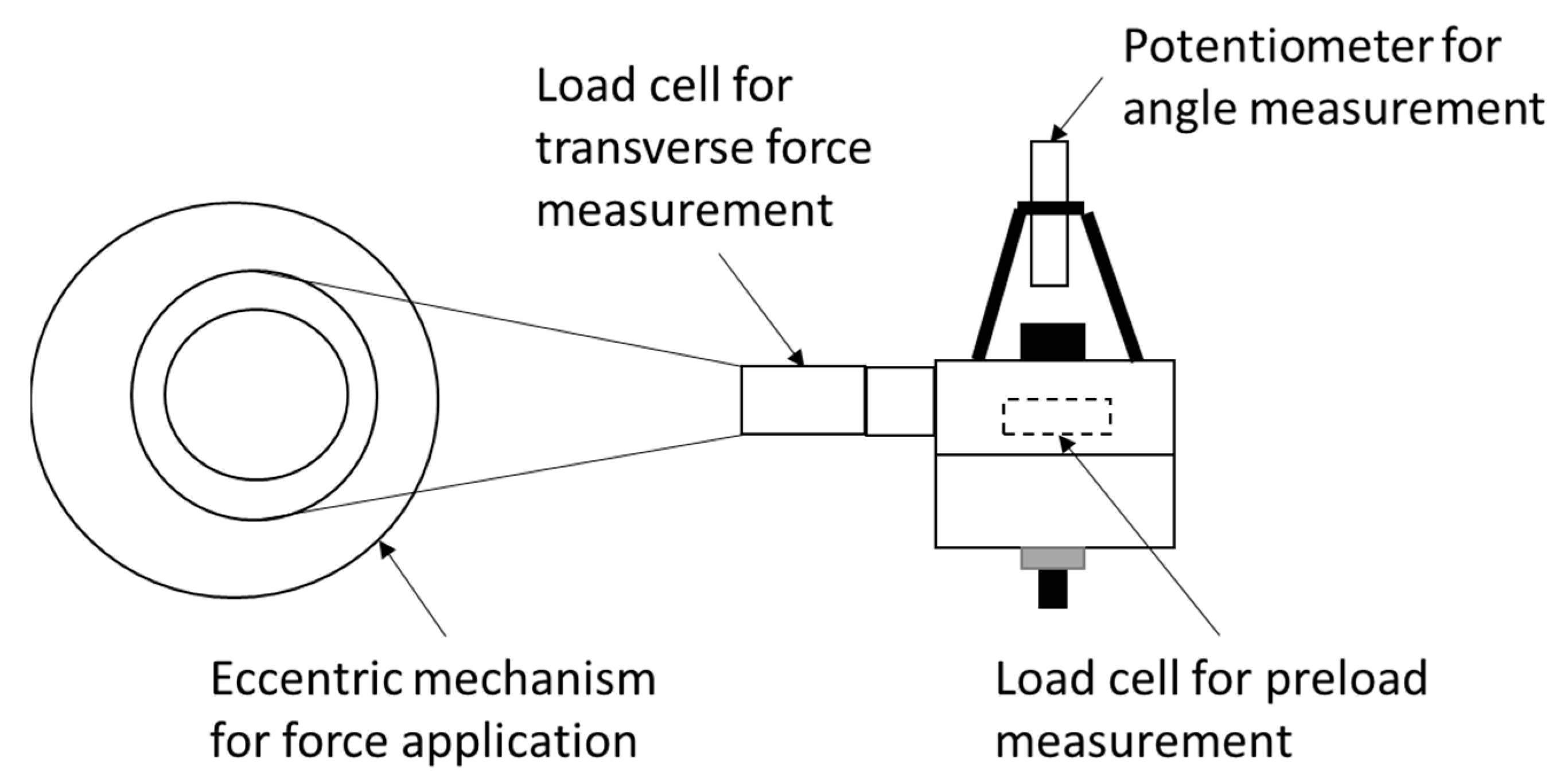
Figure 18.
The experimental apparatus used for measuring fretting fatigue in bolted joints [119].
Figure 18.
The experimental apparatus used for measuring fretting fatigue in bolted joints [119].

Figure 19.
FEA model showing (a) the boundary conditions of DLBJ, (b) mesh generation in the geometry [123].
Figure 19.
FEA model showing (a) the boundary conditions of DLBJ, (b) mesh generation in the geometry [123].

Figure 20.
Fracture surface at 30× showing the nucleation zone indicated by the arrow and the propagation zone showing the red rust [161].
Figure 20.
Fracture surface at 30× showing the nucleation zone indicated by the arrow and the propagation zone showing the red rust [161].

Figure 21.
Apparatus used in the study of impact loading on threaded connections [191].
Figure 21.
Apparatus used in the study of impact loading on threaded connections [191].

Figure 22.
Experimental apparatus for impact testing of beam-column joints [192].
Figure 22.
Experimental apparatus for impact testing of beam-column joints [192].

Table 1.
Loss of preload affected using different amounts of initial preload application for M16 steel bolt [15].
Table 1.
Loss of preload affected using different amounts of initial preload application for M16 steel bolt [15].
| Initial Clamping Force (kN) | Percentage of Loosening |
|---|---|
| 8 | 16 |
| 9 | 6.4 |
| 10 | 6.0 |
| 11 | 5.9 |
| 12 | 3.4 |
| 13 | 3.0 |
| 14 | 2.5 |
| 15 | 2.5 |
| 16 | 2.7 |
| 17 | 3.0 |
| 18 | 3.6 |
Table 2.
Theories of loosening mechanisms presented by different researchers.
| Theory | Reference |
|---|---|
| Sakai’s fixed nut and free bolt head theory | [16] |
| Junker’s complete slippage theory | [17] |
| Two-stage theory by Yamamoto and Kasei | [18] |
| Local slippage theory | [19] |
| Theory for rotational loading | [20] |
Table 3.
Review of literature on self-loosening due to vibrational loading.
| Mathematical Models | Reference |
|---|---|
| Linear self-loosening mathematical model | [26,27] |
| Non-linear self-loosening mathematical model | [28,29] |
| Incorporation of nut thread effect in a non-linear self-loosening model | [30] |
| Experimental Analysis | Reference |
| Use of microscopes to measure nut rotation | [32] |
| Junker’s apparatus for transverse excitation | [17] |
| Dinger’s apparatus for transverse and rotational excitation | [37] |
| Experimental configuration for PCB subjected to random vibrations | [40] |
Table 4.
Maximum von Mises stress (MPa) in the implant region of the implant under static, quasi-static and dynamic loading [57].
Table 4.
Maximum von Mises stress (MPa) in the implant region of the implant under static, quasi-static and dynamic loading [57].
| Thread Type | Static Loading | Quasi-Static Loading | Dynamic Loading |
|---|---|---|---|
| Square | 121.04 | 126.49 | 159.77 |
| Buttress (CF) | 173.24 | 182.33 | 239.41 |
| Reverse buttress (CF) | 205.79 | 214.42 | 298.60 |
| Trapezoidal | 237.23 | 247.06 | 358.69 |
| Triangular | 313.81 | 313.81 | 496.48 |
Table 5.
Main types of materials used for bolts in the reviewed literature.
| Serial Number | Material of Bolt | Reference |
|---|---|---|
| 1. | Carbon steel | ISO 898-1 [86] |
| 2. | Fully pearlitic high-carbon steel | Lee et al. [87] |
| 3. | SAE 10B38 steel and SAE 10B21 steel | Kodur et al. [88] |
| 4. | Stainless steel, A2–70 and A4–70 | Hu et al. [89] |
| 5. | Grade 10.9 high-performance (HP) steel | Ban et al. [90] |
| 6. | ASTM A325 bolt and A572 Grade 50 steel | Cai et al. [91] |
| 7. | Titanium alloy (Ti6Al4V) | Li et al. [92] |
| 8. | Aluminium 6082-T6 | Adeoti et al. [93] |
Disclaimer/Publisher’s Note: The statements, opinions and data contained in all publications are solely those of the individual author(s) and contributor(s) and not of MDPI and/or the editor(s). MDPI and/or the editor(s) disclaim responsibility for any injury to people or property resulting from any ideas, methods, instructions or products referred to in the content. |
© 2023 by the authors. Licensee MDPI, Basel, Switzerland. This article is an open access article distributed under the terms and conditions of the Creative Commons Attribution (CC BY) license (https://creativecommons.org/licenses/by/4.0/).
Share and Cite
MDPI and ACS Style
Croccolo, D.; De Agostinis, M.; Fini, S.; Mele, M.; Olmi, G.; Scapecchi, C.; Tariq, M.H.B. Failure of Threaded Connections: A Literature Review. Machines 2023, 11, 212. https://doi.org/10.3390/machines11020212
AMA Style
Croccolo D, De Agostinis M, Fini S, Mele M, Olmi G, Scapecchi C, Tariq MHB. Failure of Threaded Connections: A Literature Review. Machines. 2023; 11(2):212. https://doi.org/10.3390/machines11020212
Chicago/Turabian StyleCroccolo, Dario, Massimiliano De Agostinis, Stefano Fini, Mattia Mele, Giorgio Olmi, Chiara Scapecchi, and Muhammad Hassaan Bin Tariq. 2023. "Failure of Threaded Connections: A Literature Review" Machines 11, no. 2: 212. https://doi.org/10.3390/machines11020212
Note that from the first issue of 2016, this journal uses article numbers instead of page numbers. See further details here.