


Design and Control of Three-Phase Power System with Wind Power Using Unified Power Quality Conditioner

1
Department of Electrical Techniques, Technical Institute of Anbar, Middle Technical University, Baghdad 10074, Iraq
2
Department of Electrical and Electronics Engineering, Cankiri Karatekin University, 18100 Çankırı, Turkey
*
Author to whom correspondence should be addressed.
Energies 2022, 15(19), 7074; https://doi.org/10.3390/en15197074
Submission received: 2 September 2022
/
Revised: 19 September 2022
/
Accepted: 20 September 2022
/
Published: 26 September 2022
(This article belongs to the Special Issue Key Technologies and Challenges on Renewable Energies Connected to Power Systems Research)
Abstract
:The Unified Power Quality Conditioner (UPQC) is one of the Custom Power devices (CP), and it mitigates both load current and supply voltage problems (voltage swells, sags, harmonics, etc.) simultaneously. By using CP, we are getting more familiar with renewable energy’s high penetration on the electrical grid because of its intermittent nature, which causes power flection. We are also using powered electronic devices, and non-linear loads produce harmonics that affect the voltage and current waveform. In this paper, a UPQC will be used with a sensitive load that is connected to a grid (grid–wind turbine) power system. The UPQC will operate under different disturbances such as phase-to-ground fault, non-linear load on the grid side, and non-linear load in parallel with the sensitive load, using pulse-width modulation and hysteresis as switching techniques. Simulation results using MATLAB/Simulink are used to compare the two pulsing-generating techniques and show that electrical power is continuously fed to the load in all disturbances with total harmonic distortion (THD) less than 5% for voltage and 4.5% for current.

1. Introduction
Distributed generation (DG) can be defined as small-scale, bidirectional generating units that are connected to the power system at the distribution level. These units are generally considered a sustainable source of electrical power, which have a low environmental impact and power losses and can balance demand and production at the end-user side. DG units could be renewable and non-renewable resources that work together. Renewable energy sources (RESs) play a major role in DG. Using different power sources such as photovoltaic systems, wind turbines, biomass, fuel cells, and other RESs, DG aims to cover load capacity at the distribution level under different operating conditions with minimum losses, dispatch costs, and gas emissions [1]. The incessant increase in electrical energy demand leads to RES penetration in DG increment, which can affect the power quality (PQ) parameters in the utility grid, so it is important to determine the optimal size and location for DG units under certain constraints in points of common connection such as voltage profile, power flow limits, and nominal voltage values [2]. The high penetration of non-linear loads and power electronics is the main cause of voltage and current harmonics in power systems. As well, the high penetration of renewable energy systems such as PV systems, wind turbines, etc., which are installed at distribution power grids, increases every day because of power systems structure development [3]. This penetration presents new power quality challenges for distributed generation systems. Additionally, low power quality can negatively affect the performance of sensitive loads connected to the grid. Many researchers are making efforts to improve power quality. Several solutions have been found for PQ improvement, such as the series active power filter (SAPF) to handle voltage harmonics and the parallel active power filter (PAPF) to eliminate current harmonics caused by non-linear loads [3]. In [4], a harmonic active filter has been used with four wind turbines connected with a 33 kV utility grid. The current THD was 7.44% when all the wind turbines operated together and 15.95% with only one wind turbine. Additionally, a passive filter has been used as a conventional solution [5]. Different types of passive filters were applied with a small-scale wind turbine which operates with different wind speed values (6–13 m/s). The lowest THD value was 11.42% for the current and 5.84% for the voltage. In [6], hybrid filters were used with four grid-connected wind turbines, and the proposed hybrid filter consists of a series active filter and a passive filter, which was considered a good solution to minimize the installation cost for APF.
A shunt active filter can be used to eliminate current harmonics provided by non-linear loads. An SAF consists of an inverter and a DC source. There are many topologies to generate pulses for electronic switches in an inverter, such as pulse-width modulation or hysteresis. The DC source can also be a renewable energy-generating unit such as PV or fuel cell. In [7], using a fuzzy logic controller lowers the current THD from 28% to 4.85%. For improving active power filter performance, conventional controllers can be used, or expert systems controllers such as fuzzy logic to detect current harmonics and drive the APF, especially with the presence of RES where the generated power changes rapidly according to the resource nature. In [8], the current THD for grid-connected 60 W PV was 3.54% with the non-linear load.
One of the most effective tools for addressing problems with voltage and current quality is the unified power quality conditioner (UPQC). A UPQC consists of parallel active power filters and series active power filters. The UPQC is a power conditioning tool that may correct various power quality issues [9]. A non-linear load’s harmonics are eliminated by a shunt active filter, while supply voltage flicker and imbalance from the load terminal voltage are removed by the series active filter component.
The UPQC filters harmonics and reduces current and voltage power quality issues. Therefore, the UPQC is seen to be a very excellent solution to power quality issues, and there is no need to employ several installations in the distribution system. D-Q theory may also be applied in the controllers for the series and shunt compensator. The UPQC can regulate voltage amplitude, and it has been used in [10] with an 11 kV utility grid, where it reduced voltage sag and swell by 73%.
The UPQC cannot compensate for voltage interruption without an energy storage system or an indented power-generating unit to feed the DC link voltage of back-to-back inverters in the UPQC. By using this installation, the UPQC can provide power to the sensitive loads during islanding, which may occur during faults in DG [11]. It can also regulate the power quality parameters on the load side regardless of the changes on the grid side. A smart grid has both direction power flow and information, monitoring and reacting to variations in everything from power plants to distinct consumer appliances. Therefore, with the high implementation of distributed generating systems (DGSs), the quality of power supply has become a notable problem for micro-grids or smart grids. Table 1 shows the PQ problems in distribution power systems [12].
The synchronous reference frame approach is used in a series of active filters to determine the fundamental component of voltage. However, in parallel active filters, the instantaneous reactive power theory (IRPT) is used to extract the fundamental current. This method was proposed in [13] to reduce voltage THD to 3.8% and current THD to 4.5% under unbalanced load conditions. In a [14] study that compared STIA, PI, and PID controllers in the UPQC under different operating conditions, voltage THD was 10.3% with PI, 7.5% with PID, and 0.2% with STIA.
Several studies have proposed different control techniques for generating reference voltage and current, such as gate-pulse generation using PWM controllers and a capacitance-balancing or hysteresis current controller (HCC), multilevel vector-based hysteresis current controller (MVHCC), and adaptive hysteresis current controller (AHCC) [15]. Furthermore, the controller for series and shunt inverters can be based on a variety of methodologies, including instantaneous power theory, the load-equivalent conductance approach, and fuzzy logic controllers [16], etc. Ref. [17] proposes a single-phase universal power compensator (UPC) system with equal reactive power sharing between the series and parallel APF of a UPC to increase PQ and alleviate voltage and current concerns. The equal VAR sharing function makes it possible for series and shunt active power filter (APF) inverters to have the same rating. To achieve equitable VAR sharing amongst the active filters, a synchronous reference frame based on direct power angle computation is employed. This power angle calculation for current parameters taken from the d and q axes is used to create the reference signal for a shunt active power filter. When compared to other standard approaches, the synchronous reference frame method is quite beneficial for power calculations. The current THD was reduced to 3.5%. In [18], an intelligent control technique for maximum PQ improvement in a hybrid grid-tie power system comprising PV panels, a battery bank, and a wind turbine is proposed. In a grid-tied renewable energy system, a UPQC with active and reactive power (UPQC-PQ) includes atom search optimization based on a fractional-order PID controller. The suggested approach attempts to reduce the THD by controlling the voltage at the point of common connection (PCC), lowering loss, and mitigating harmonics. The suggested technique additionally uses atom search optimization based on a fractional-order PID controller to alleviate PQ difficulties. Ref. [19] describes a compensation method for non-active voltage/current components that use a UPQC and is controlled by a conductance signal. The active power of the corrected load can be used to generate the conductance signal. Two variables, load power and the supply voltage, can be used to estimate this signal. It is possible to avoid the difficult ways of evaluating voltage or current waveforms by decomposing them into several components by utilizing the conductance signal as the reference for the UPQC. When combined with the UPQC, the conductance technique permits bidirectional power transfer with a unity power factor from the source to the load and vice versa when the load can create power. This allows the UPQC to be used as an energy buffering and distribution center, which may be highly useful in smart microgrids. The UPQC may be employed with grid-connected renewable energy systems such as solar PV systems and wind turbines [20,21], and the DC-AC converter can influence the THD for protected loads such as half-bridge or multilayer inverters [22]. Ref. [23] investigated a nine-level converter for the planned UPQC. The UPQC connects the PV system to the electrical grid. Then, a novel method for generating pulses for transistors on both UPQC inverters is presented. This is based on an adaptive hysteresis band (AHB) defined by FLC to obtain the output voltage with the least amount of THD. The goal of a UPQC connected to a wind turbine is to compensate for reactive power to control voltage and eliminate the THD in the PCC. The UPQC may be said to enhance the PQ at the PCC for distribution grids [24,25]. In [26], a control approach for compensation by employing a UPQC coupled with a DFIG on a poor distribution system is described. The suggested compensatory approach enhances the system PQ by taking advantage of DC-bus storage and active power-sharing on UPQC inverters. The findings demonstrated a satisfactory reaction to AP fluctuation caused by the “tower shadow effect” and voltage regulation caused by a rapid load connection. In this paper, we attempt to improve all power quality issues for voltage and current (harmonics, voltage sag, swell, and drop) for the protected load, which is connected to the electrical grid with a wind turbine. The UPQC is used to improve power quality at the PCC for sensitive loads with wind turbine–grid power systems during different disturbances. We then compare the results for PWM and hysteresis-pulsing-generating methods.
2. Materials and Methods
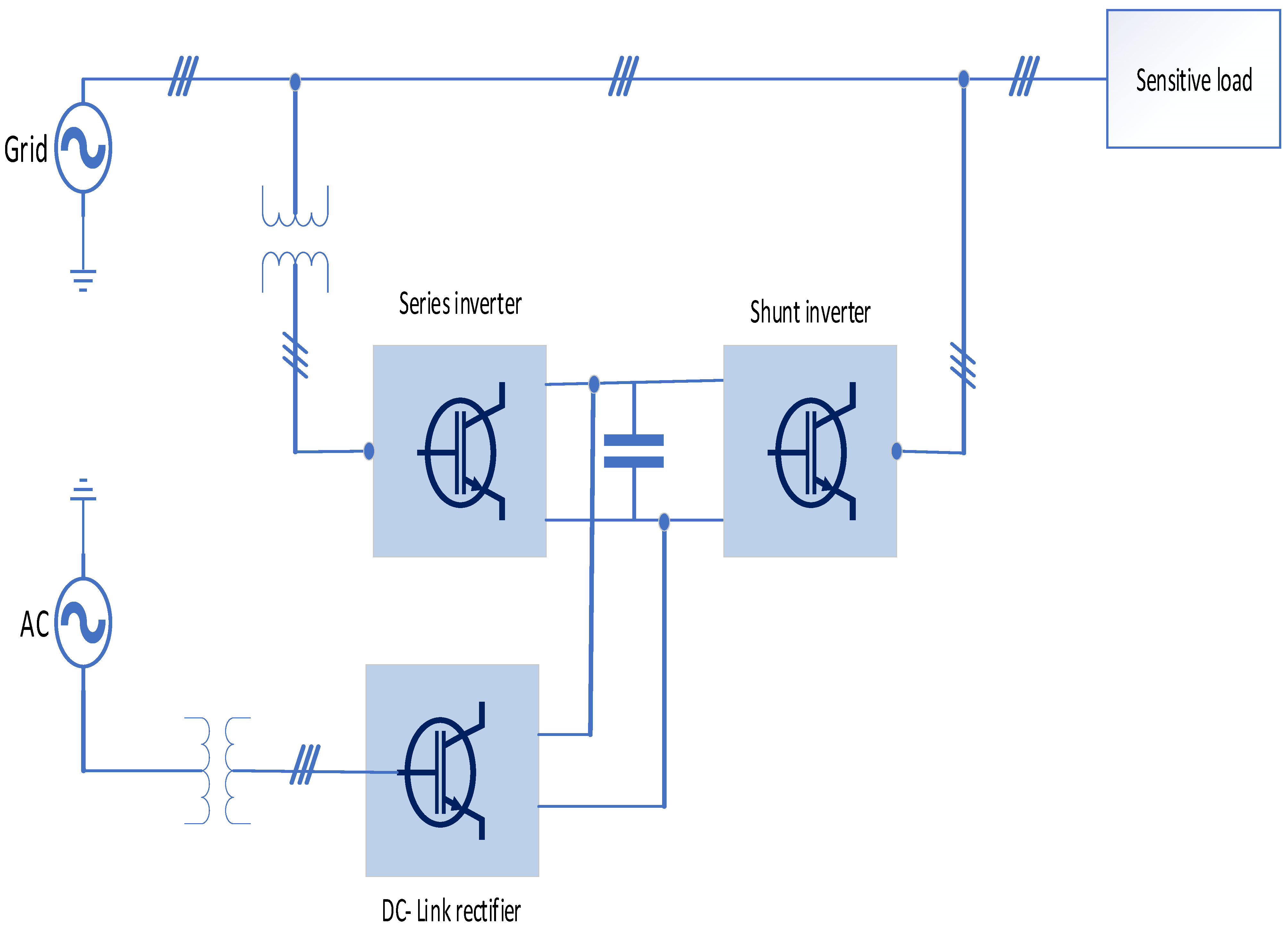
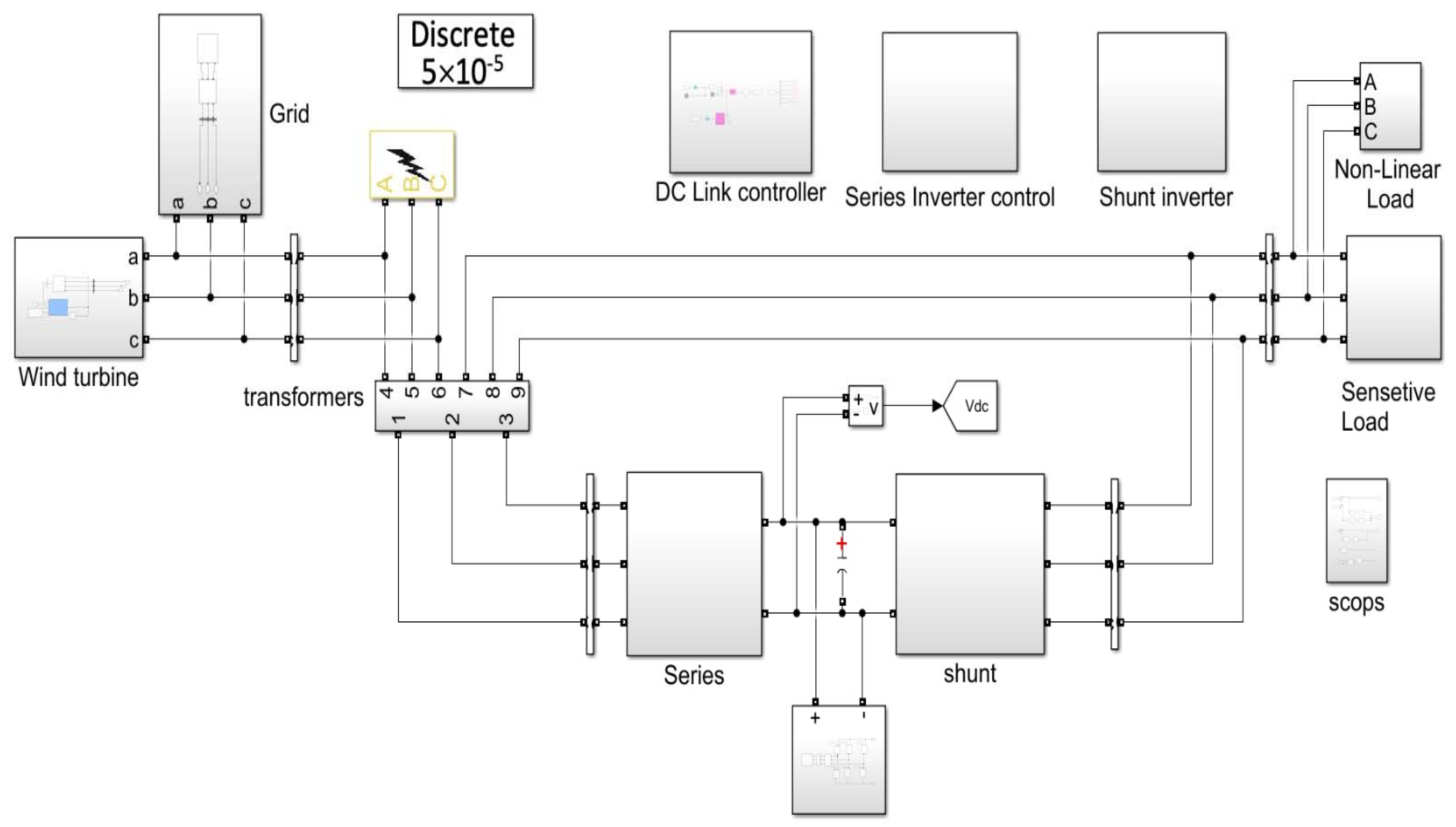
The UQPC includes two half-bridge inverters, one in series and the other in parallel with the load. As shown in Figure 1, both converters share the same DC connection, which has a separate AC voltage source with a rectifier to regulate the DC voltage [27].
2.1. Series and Shunt Inverters
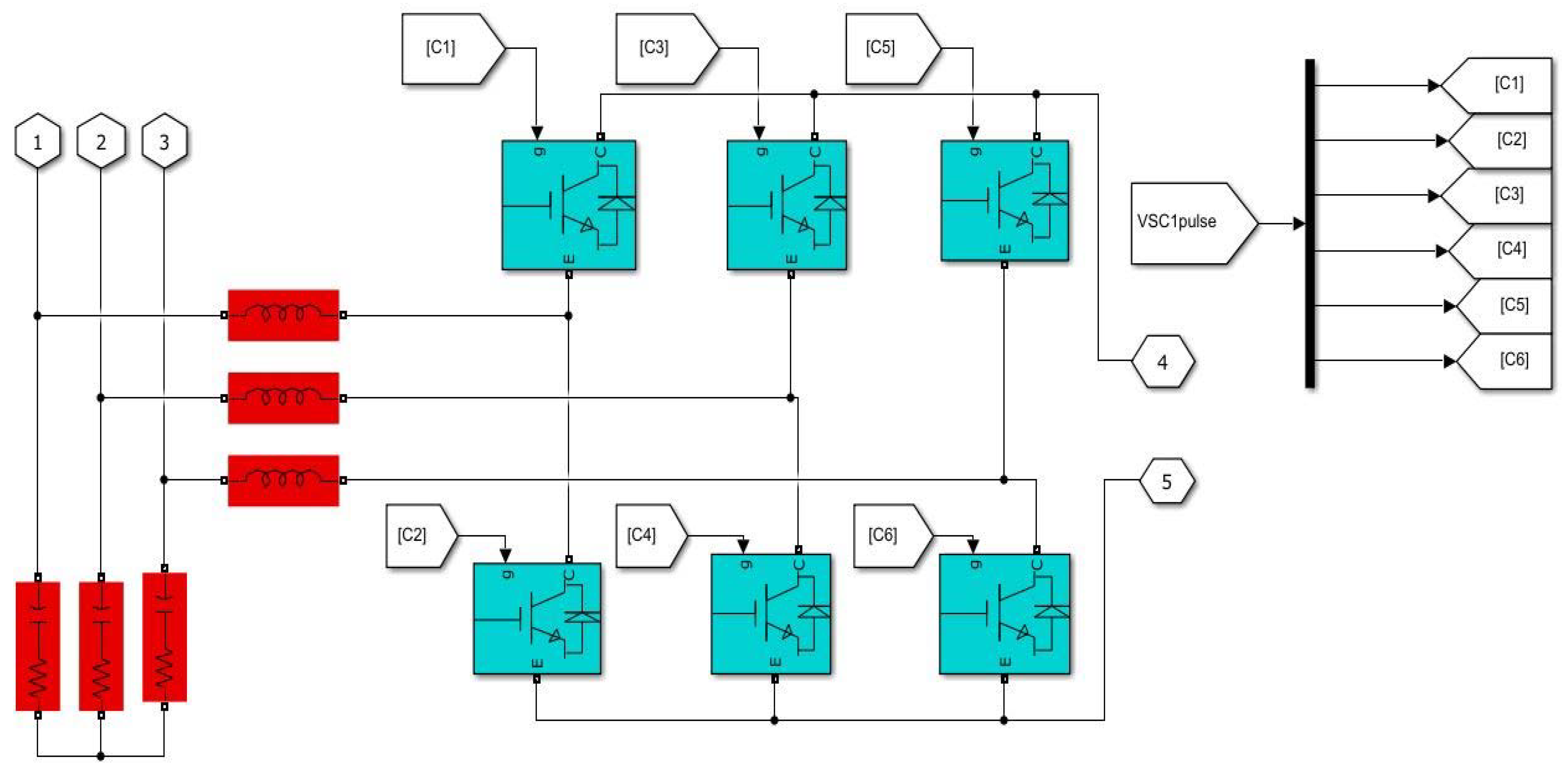
Both of them consist of six transistors (half-bridge, three-phase inverters), as illustrated in Figure 2. Series one is connected to injection transformers through a 2nd-order filter (LC filter). The series port of the UPQC plays the role of a series active filter. The other inverter is connected to the load and grid through a 3rd-order filter (LCL filter). This part is used as a shunt active filter.
2.2. DC Link Rectifier
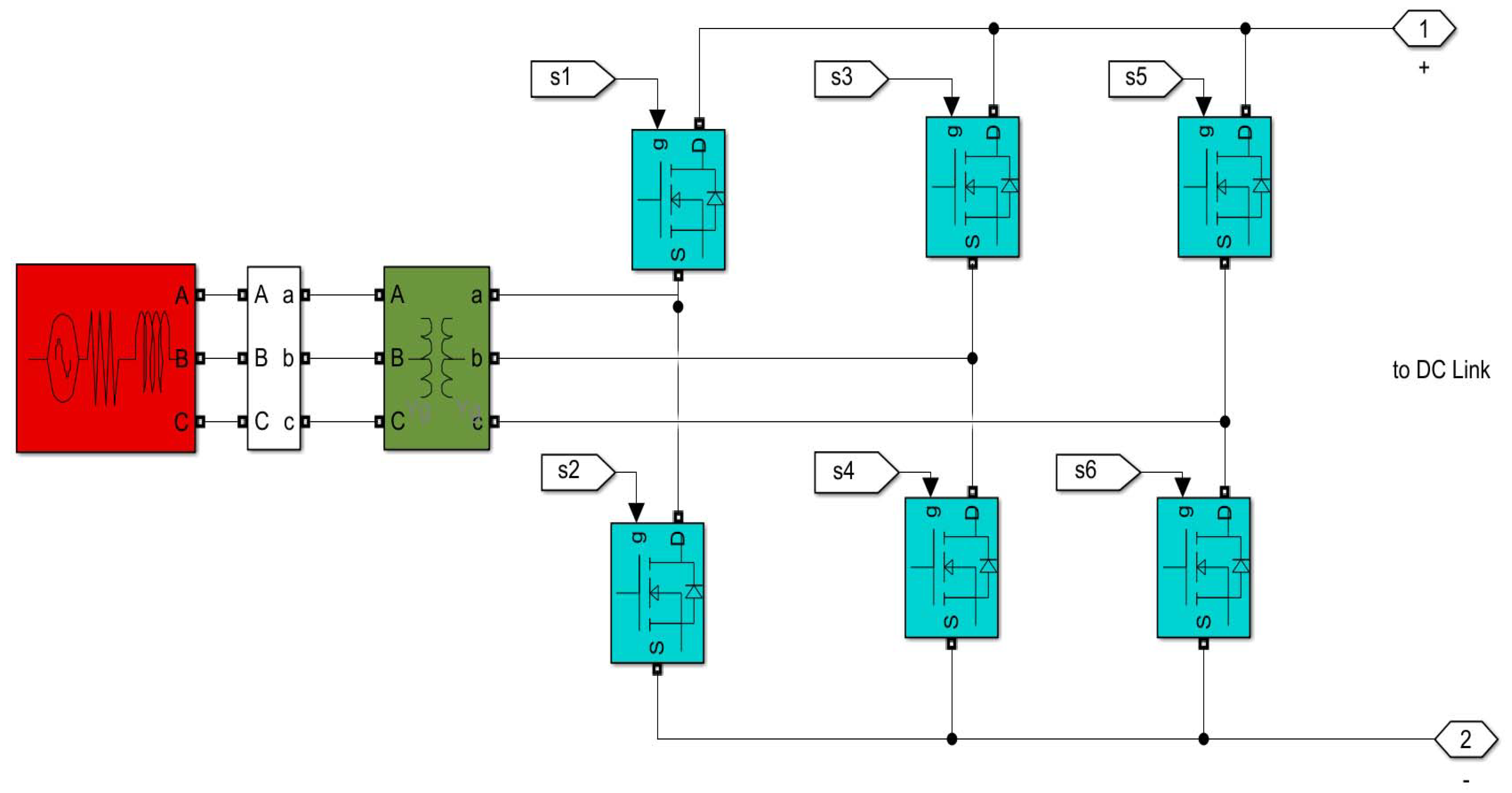
This component is responsible for providing the DC voltage for the inverters. The DC voltage should be higher than the peak value for AC voltage. That is why we use a step-up transformer, and a close-loop rectifier regulates the DC link voltage. Figure 3 shows the simulation for the rectifier with an AC source and transformer [28,29].
3. Generating References
The series inverter needs a reference voltage signal, and the shunt inverter needs a reference current signal. There are many methods to generate these signals, and some of them depend on the frequency domain, which has a very high computational cost. In this paper, the instantaneous power theory is applied, which depends on the time domain.
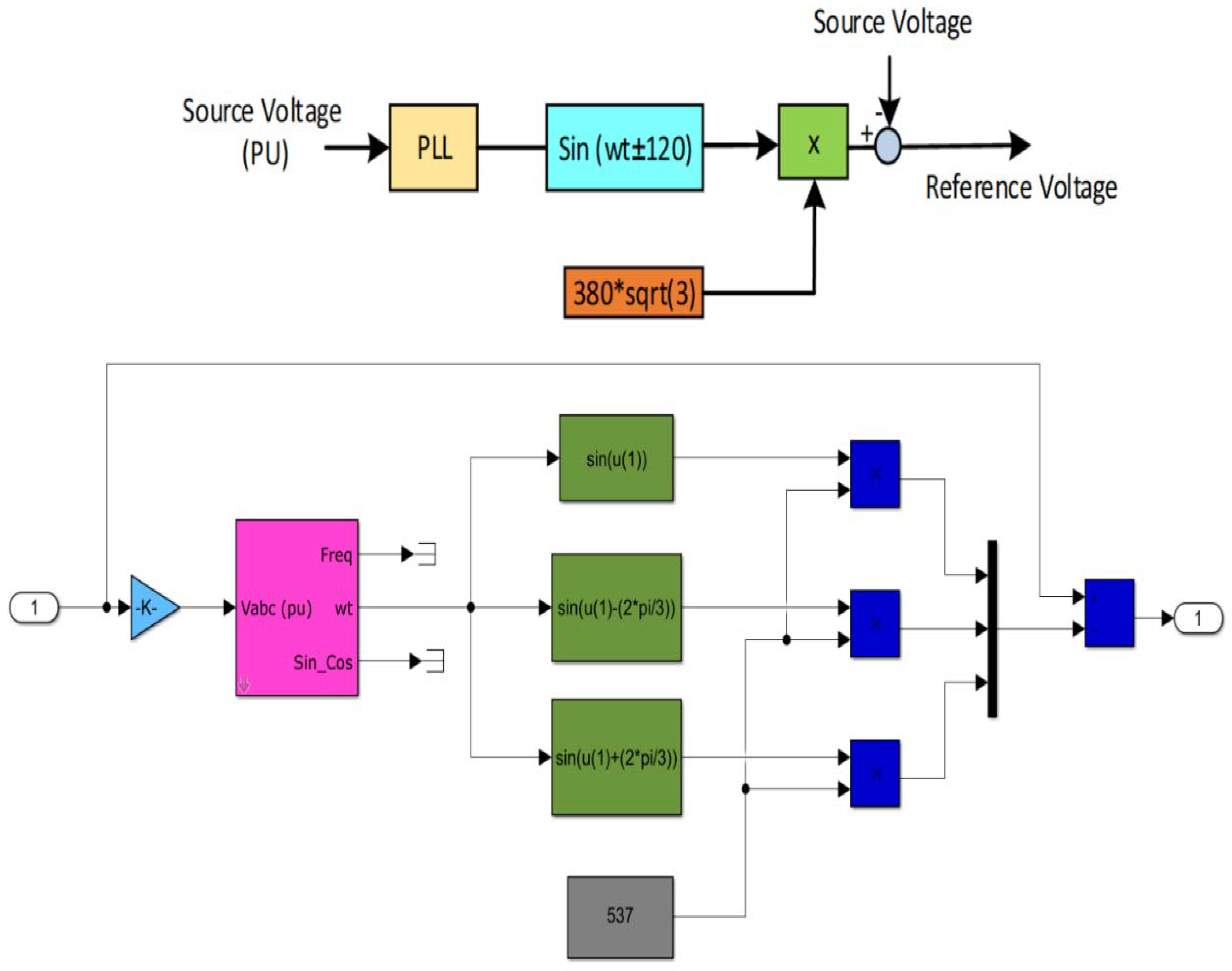
3.1. Series Inverter Controller
This controller is responsible for generating a voltage reference for voltage disorders, creating a pure sine wave control signal to compare it with the actual voltage for the load as follows [30]:
where stands for the fundamental component from PLL, is equal to zero for phase a, equal to −120 for b, and 120 for c,: is 537 = 380 ∗ Sqrt (3) for the peak value of phase to phase voltage. This controller and its simulation are illustrated in Figure 4.
Phase-locked-loop (PLL) is used for grid voltage monitoring, and its performance directly affects the dynamic response for the UPQC because it is a very effective way to detect abnormal operating conditions in the utility grid. The PLL regulator is scaled according to the input signals’ magnitude. The minimum frequency for PLL was 45 Hz, and the regulator’s gains were [Kp = 180, Ki = 3200, Kd = 1].
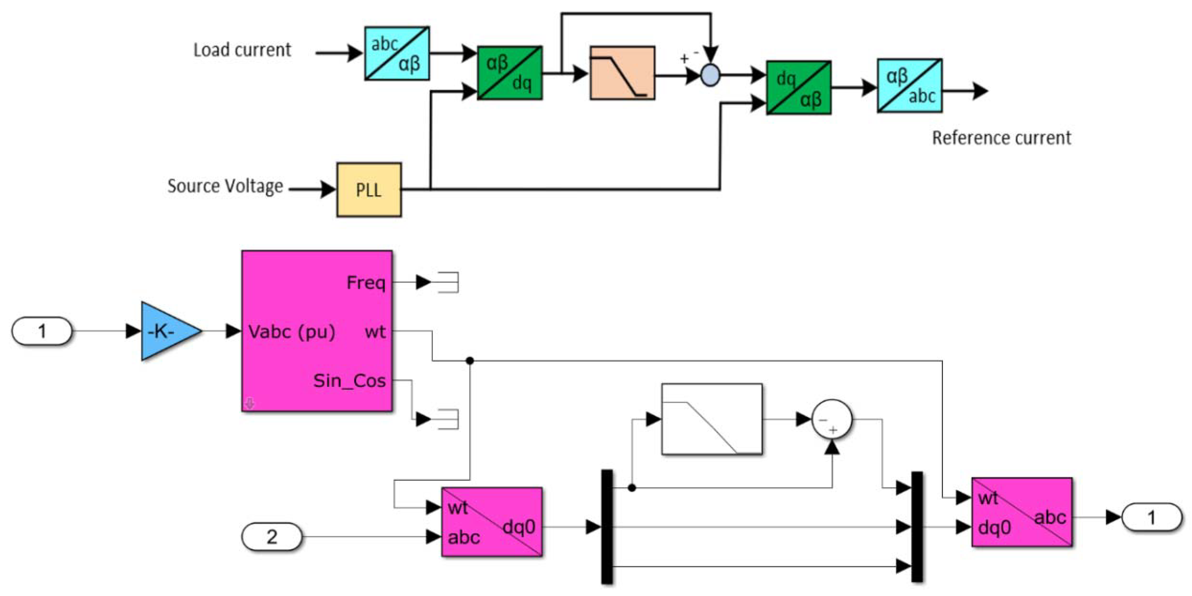
3.2. Shunt Inverter Controller
This part is responsible for current disturbances, especially harmonics. By using Clark transformation with low-pass filter disturbances, this can calculate the reference current. The (ABC) voltage and current are transformed to 0, α, and β, which is shown as [31]:
Figure 5 illustrates the shunt controller and its simulation.
After using d-q transformations, the reference current is computed as follows:
where refer to the shunt active power filter.
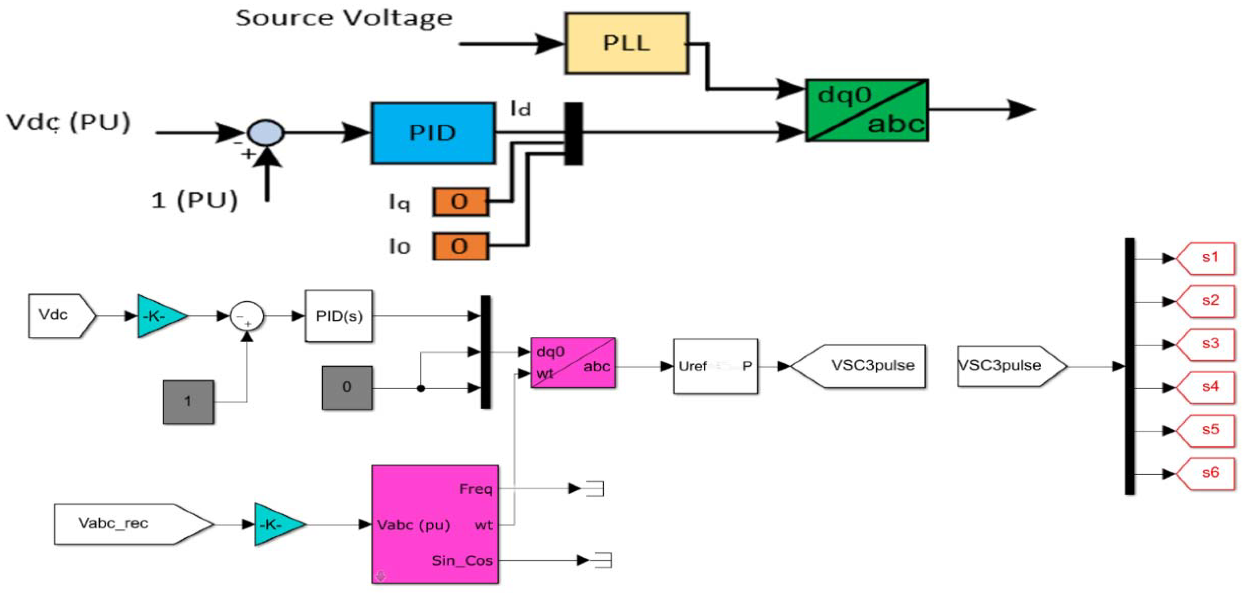
3.3. DC Link Control System
This system’s function is to regulate the DC voltage for the back-to-back inverter. DC voltage is essential for power and harmonics injection. Using the electrical grid for a power source is not recommended because the series part of the inverter is responsible for voltage power quality issues which will be affected by faults and power flickers in the grid. Figure 6 shows the control system for the DC link.
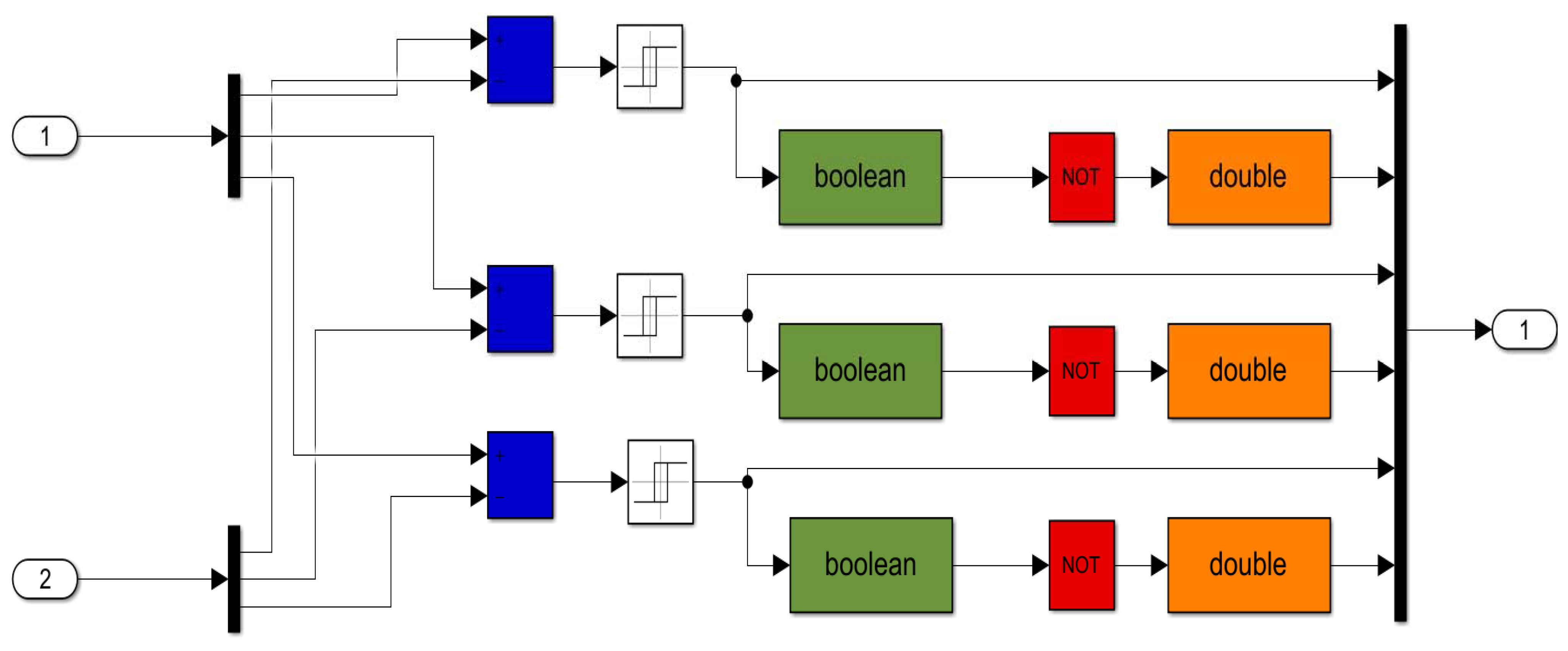
4. Transistor Pulsing Systems
As mentioned before, two techniques are used for generating pulses for transistors. The first one is hysteresis. This method gives pulses when the error reaches the upper or lower limits [29]. The simulation for the three-phase controller is illustrated in Figure 7.
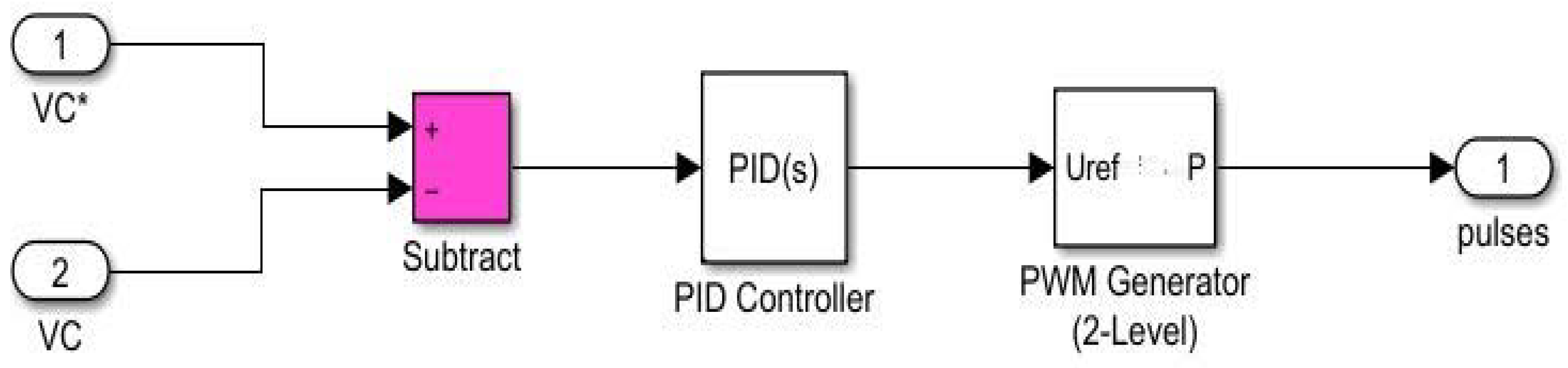
The other is a PI controller with PWM. This technique uses a sine wave as a modeled signal and a sawtooth signal as a carrier. The pulses are generated when intersections happen between them. Modeling this technique can take many shapes. Figure 8 shows the simulation for PWM with PID.
Here, VC is the voltage injected by the converter, and VC* is the calculated reference voltage for the series converter in the UPQC.
5. Wind-Turbine-Generated Power
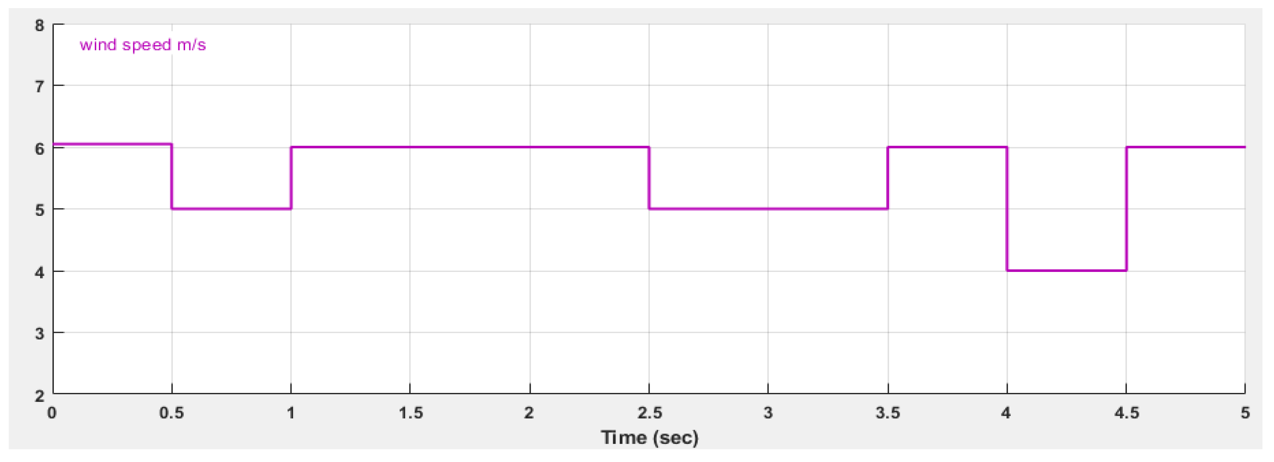
In judging the UPQC performance under different cases, some inputs will be the same in all cases, such as wind speed, load, and generated power from the wind turbine. Figure 9 shows wind speed during a 5 s simulation.
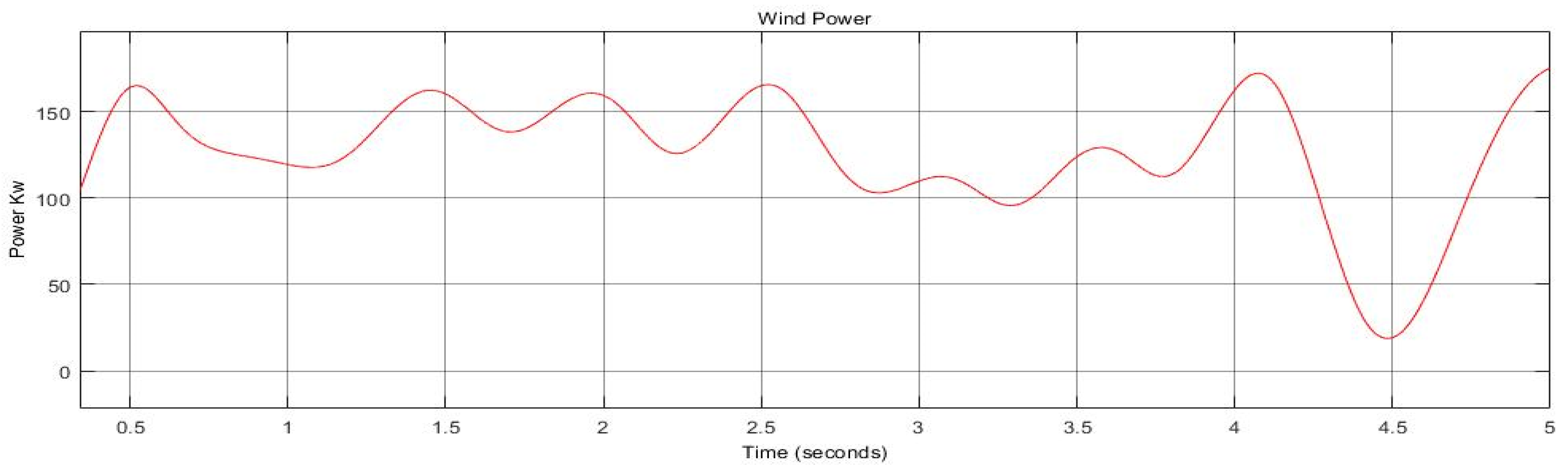
Figure 10 shows the generated power from the wind turbine in kW.
6. Simulation Results for Case Study
In this section, we show and discuss the results of various cases. The main purpose of using the UPQC, in this case, is to keep the sensitive load fed in:
- Non-linear load on the grid side.
- Non-linear load connected in parallel with the sensitive load.
- Phase to ground fault.
- All the above with different values of wind speed.
- Using pulse-width modulation and hysteresis band techniques for pulsing transistors [32].
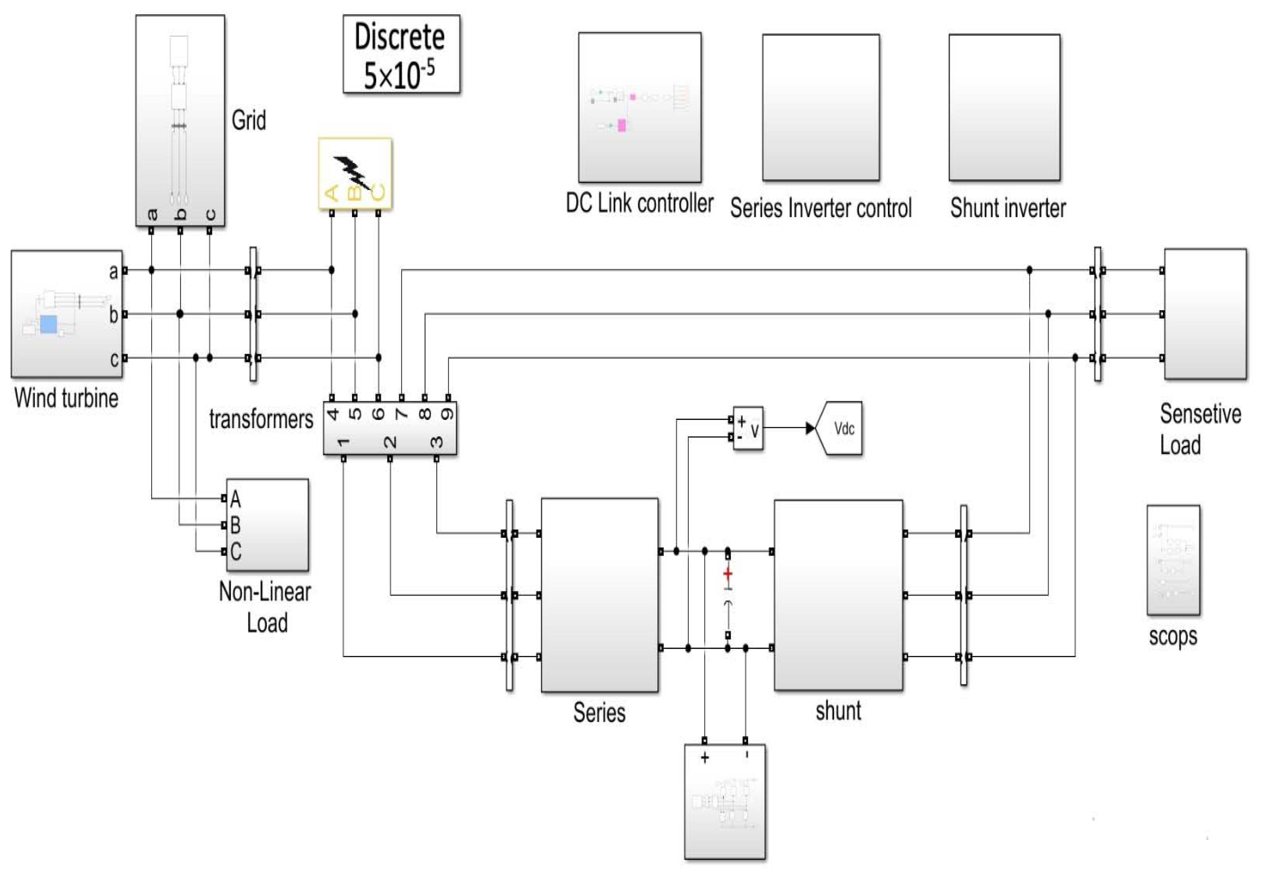
6.1. Non-Linear Load on Grid Side
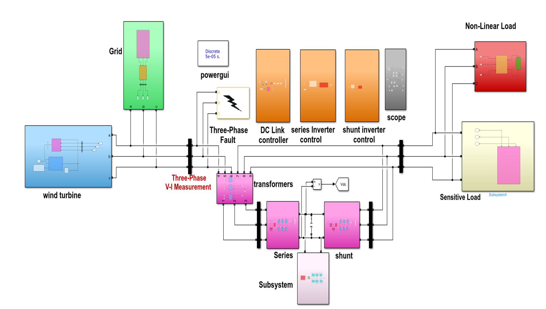
The full simulation for this system is illustrated in Figure 11. The general concept for the power system is the same for the pulsing techniques used. The only difference is that in the first case, we use hysteresis, and in the second, we use PWM.
6.1.1. Using Hysteresis Technique
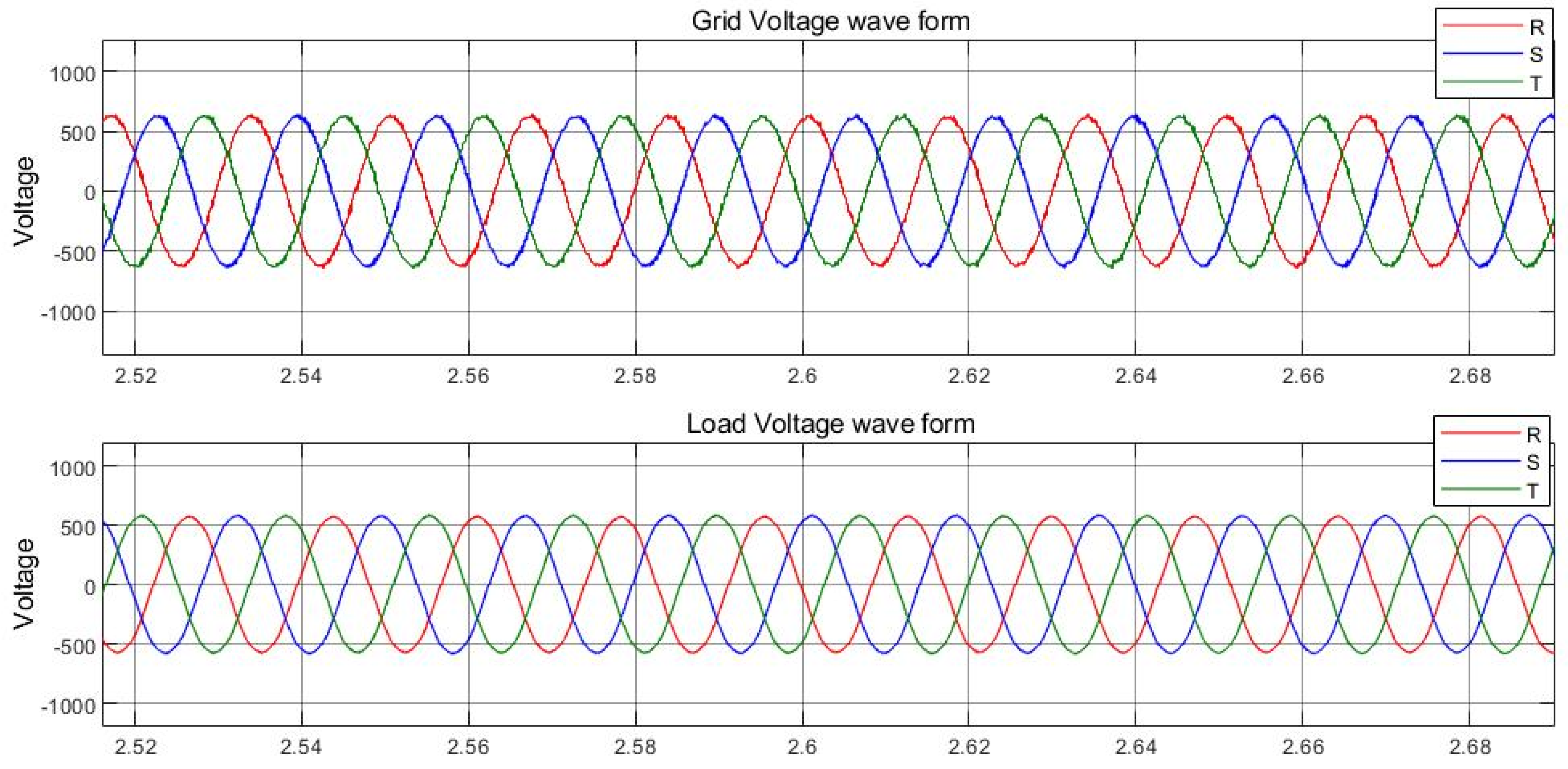
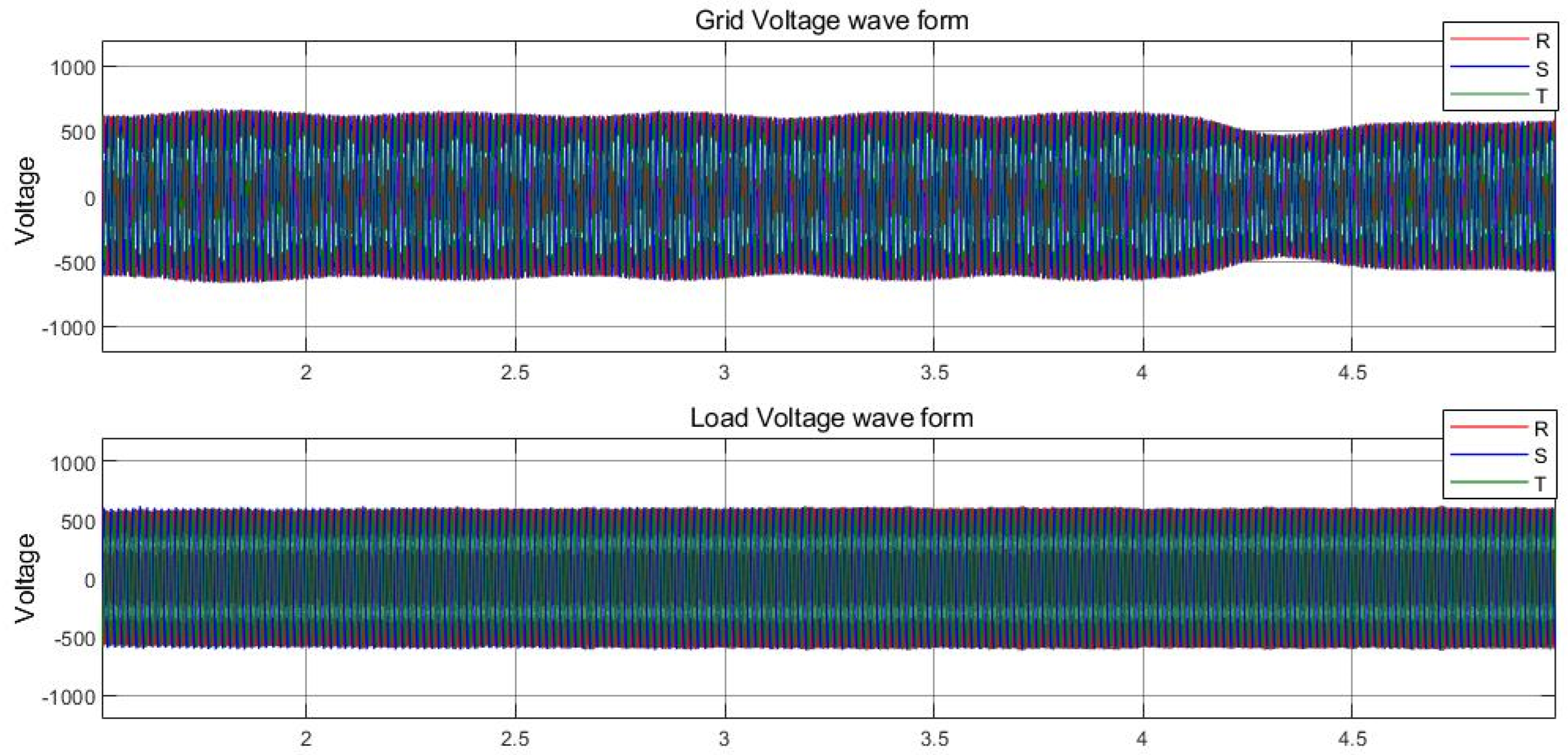
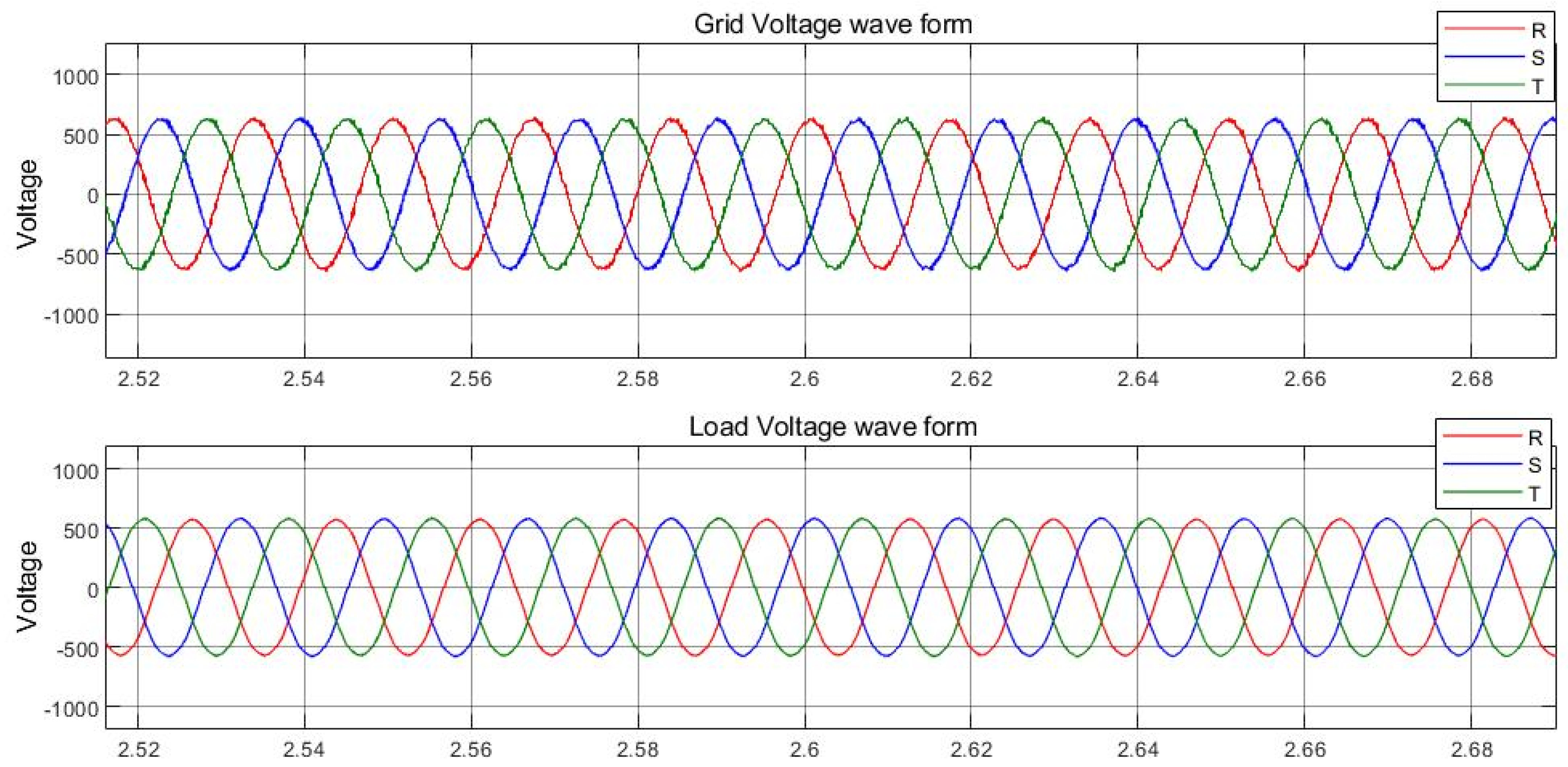
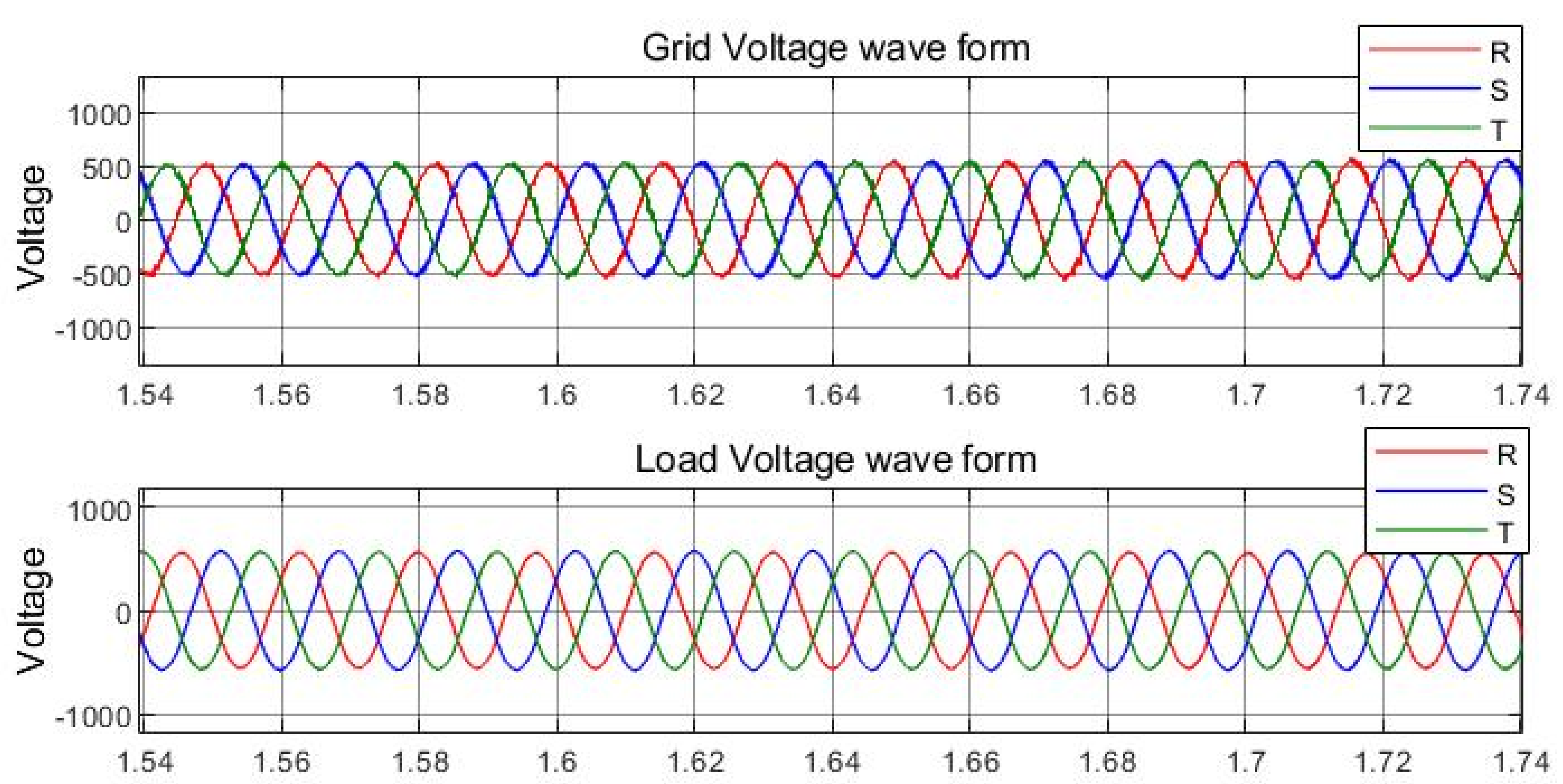
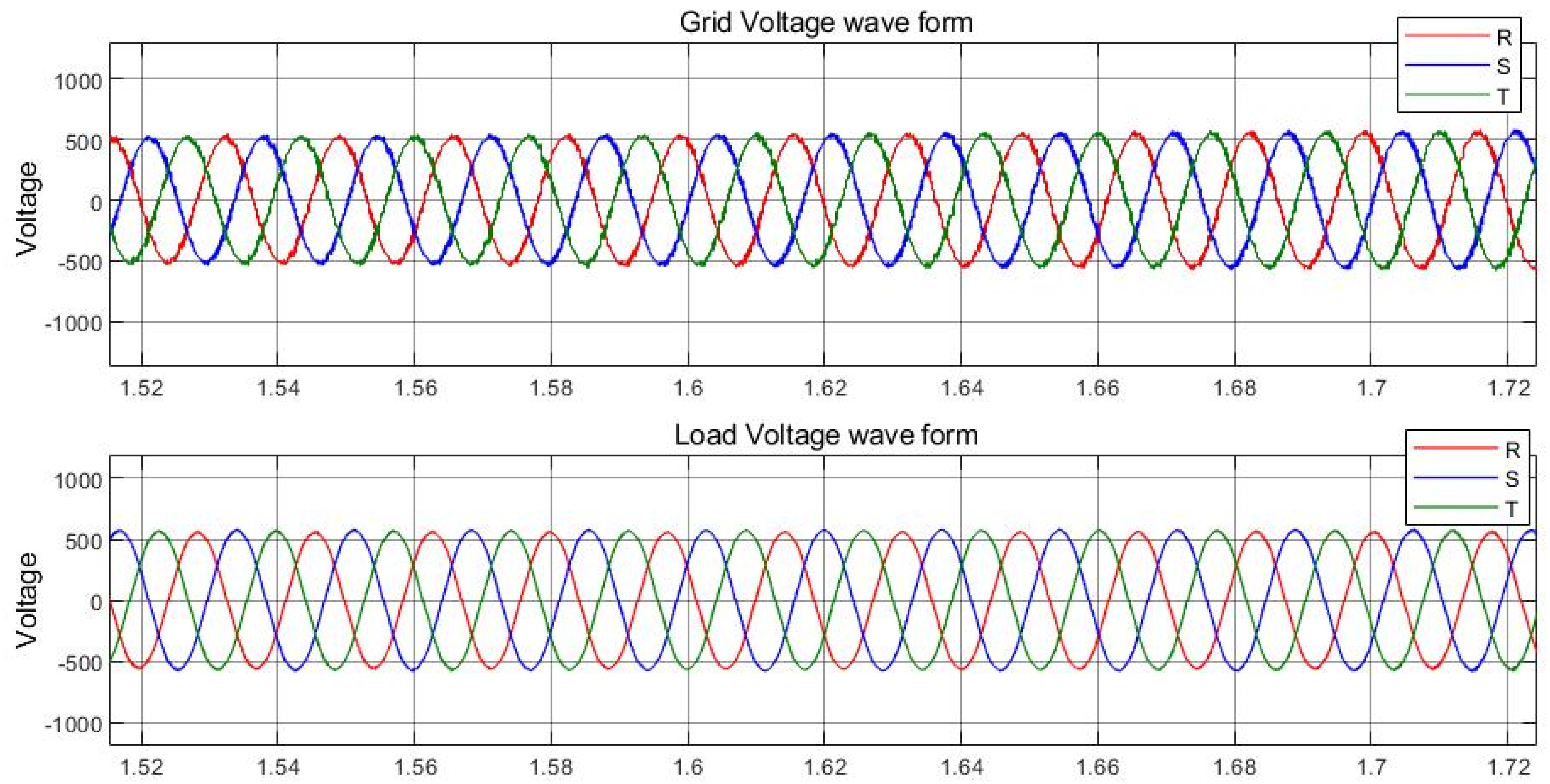
Figure 12 shows the grid-side voltage and load side when there is a non-linear load injecting harmonic on the grid.
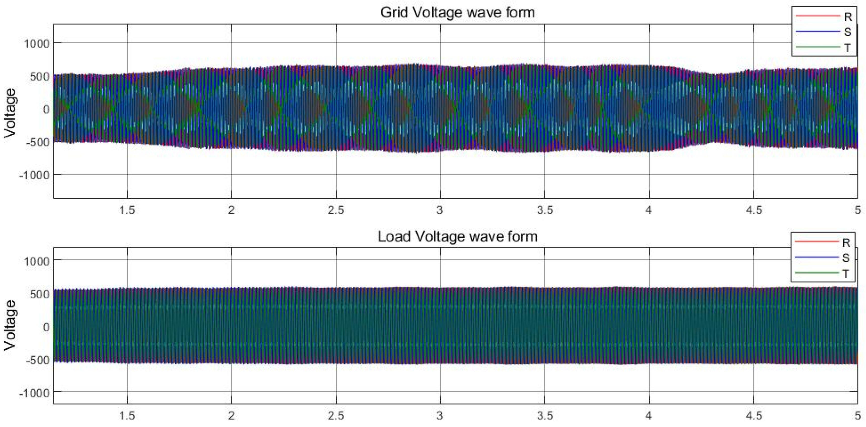
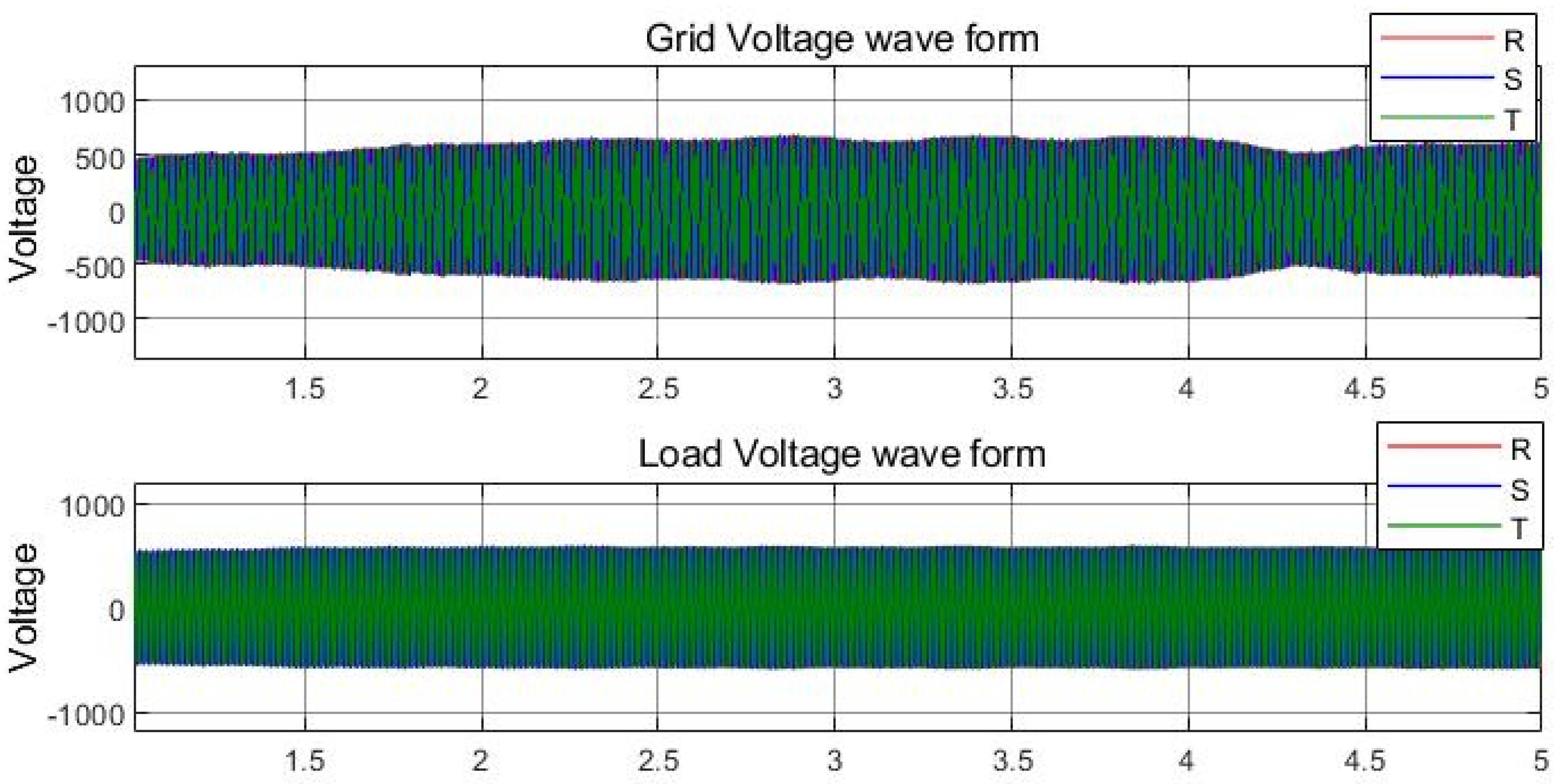
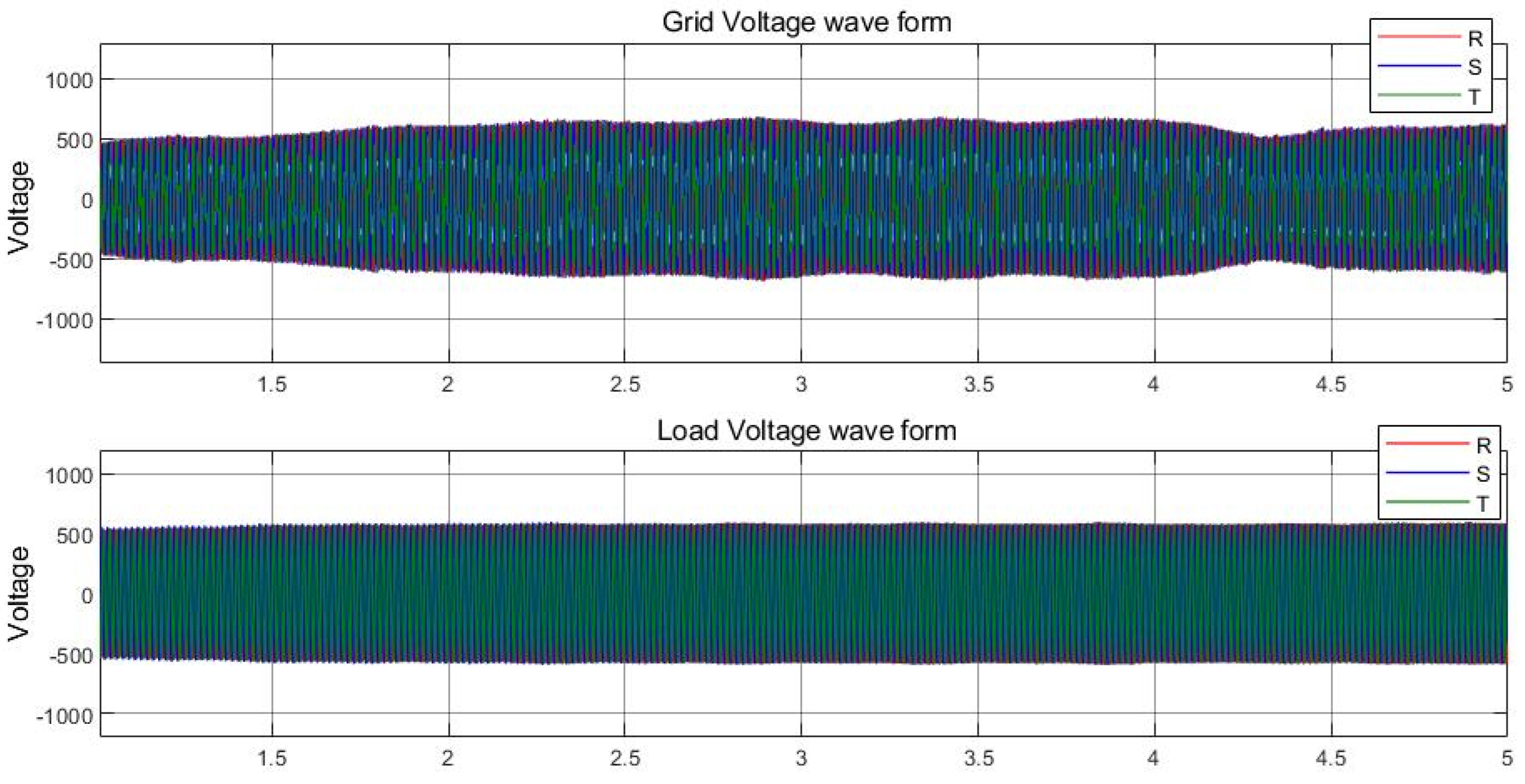
Figure 13 shows the grid-side voltage and load-side amplitude during the simulation.
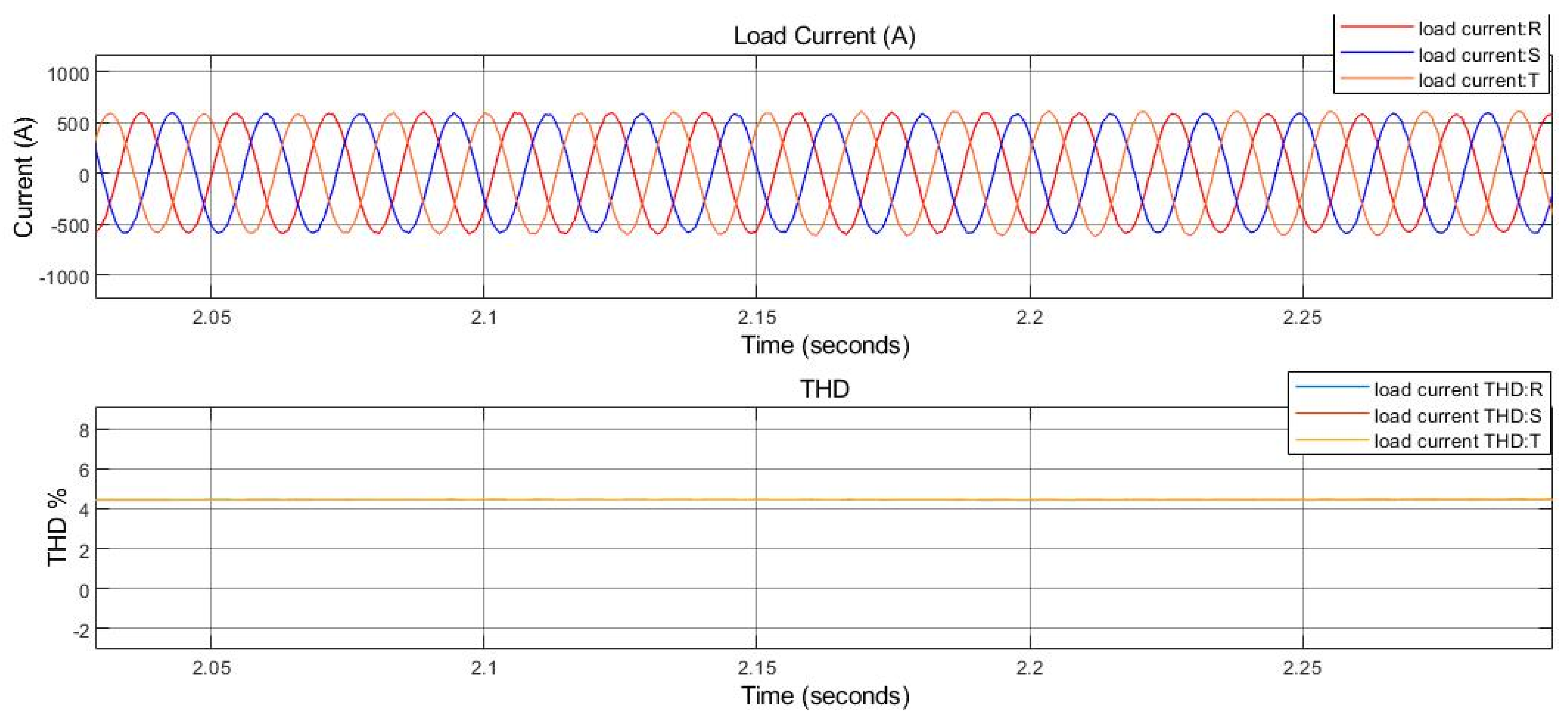
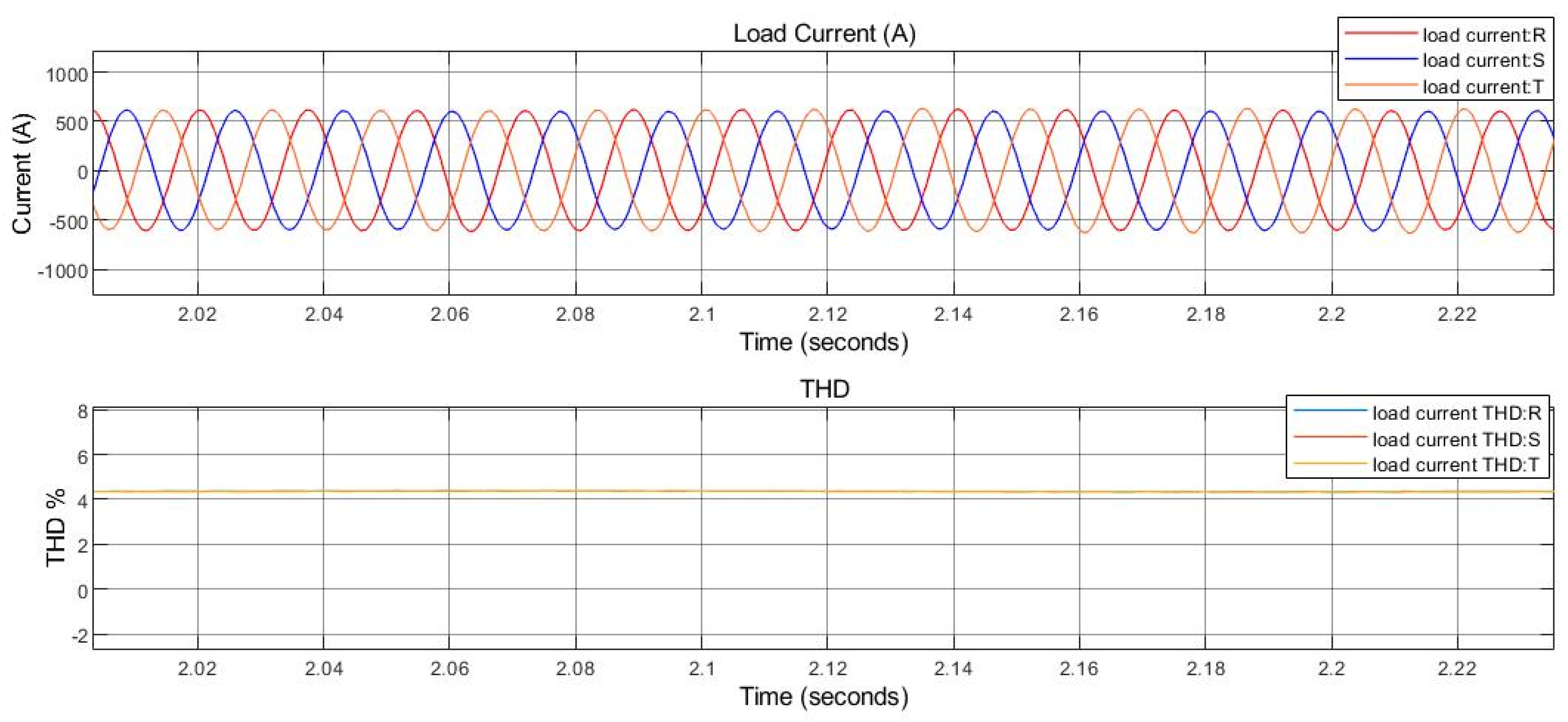
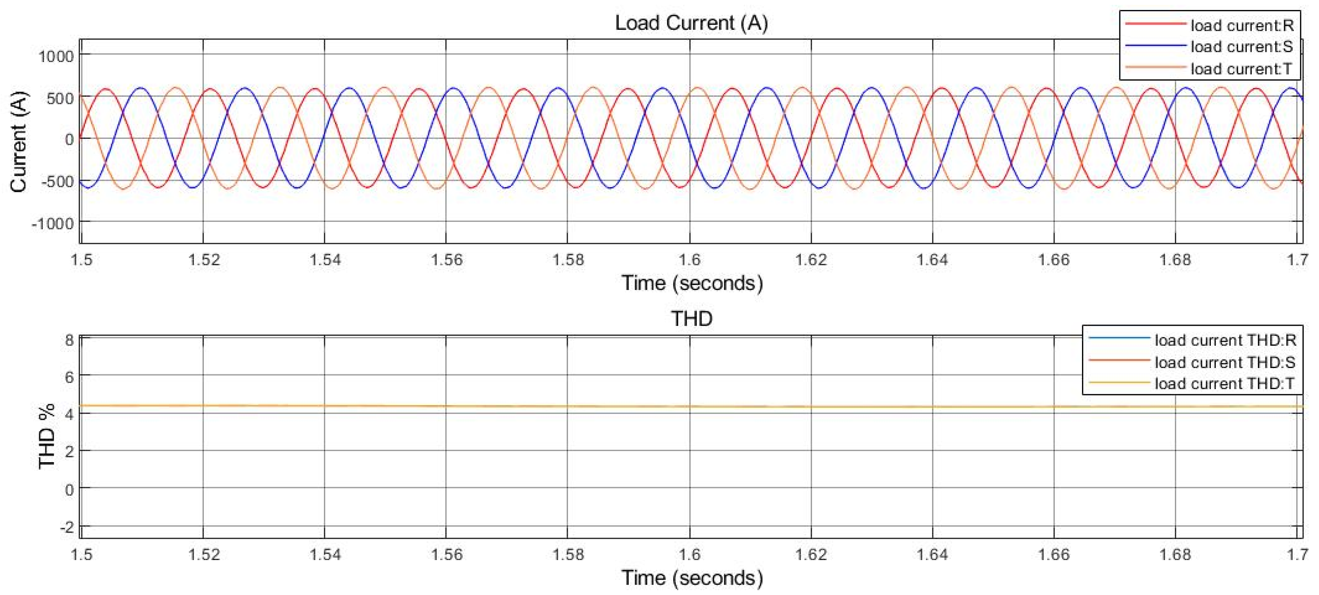
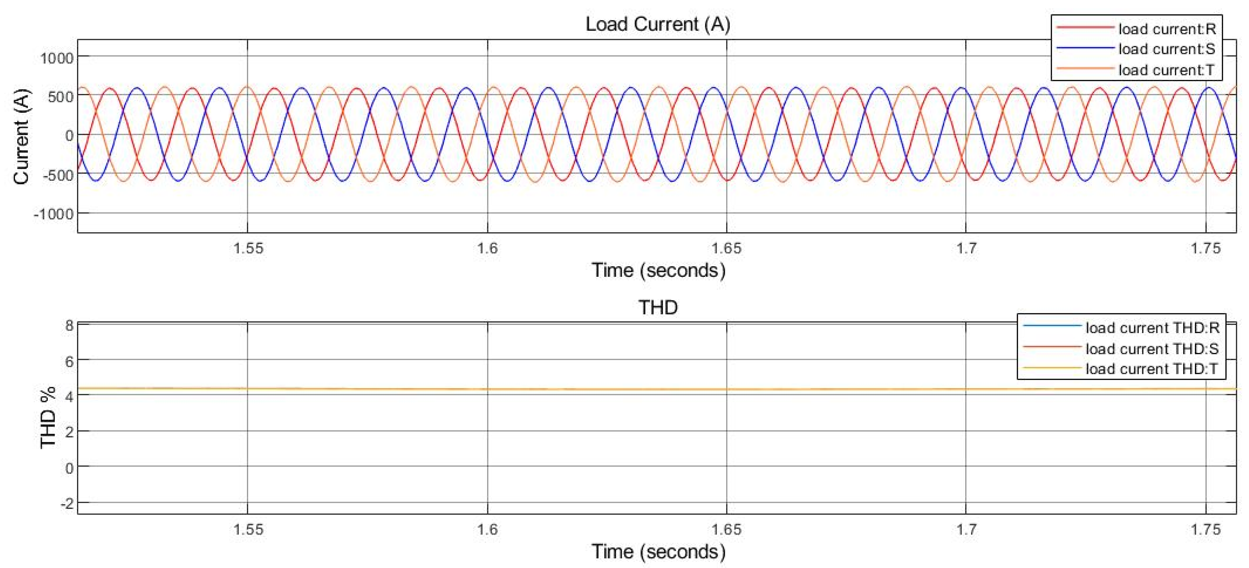
The voltage on the grid side has a THD between 10 and 8%, but on the load side, the THD does not pass 5% during different operating conditions. The main purpose of using the UPQC is to keep electrical feeding for the load with high quality. We use a 250 KW load with 5 KVR as a sensitive load. Figure 14 shows the load current and THD using hysteresis.
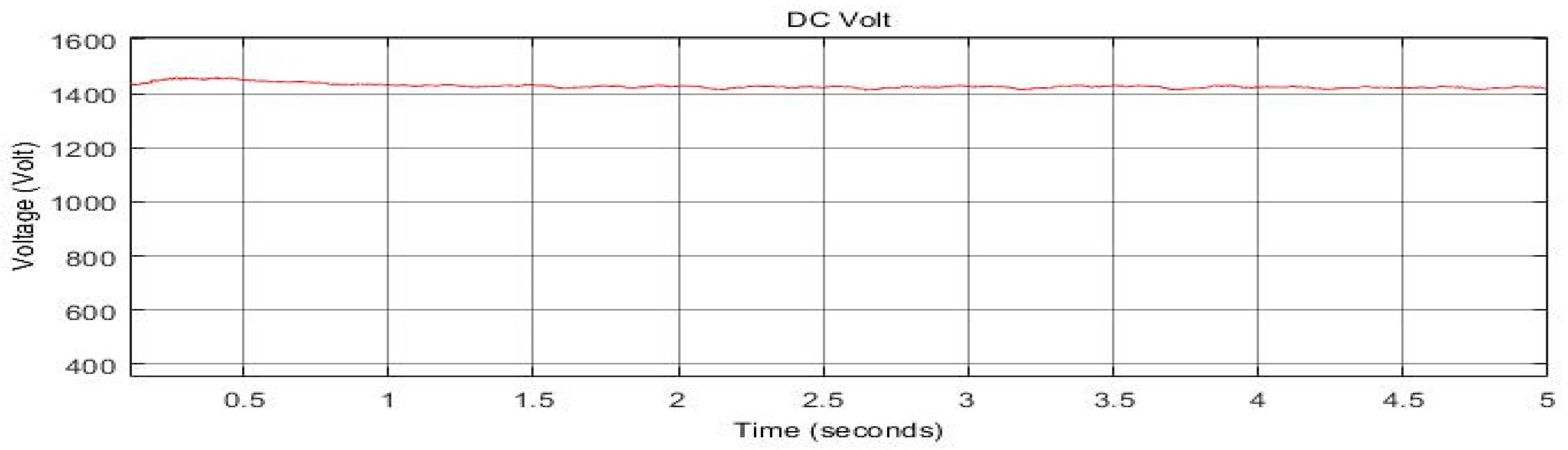
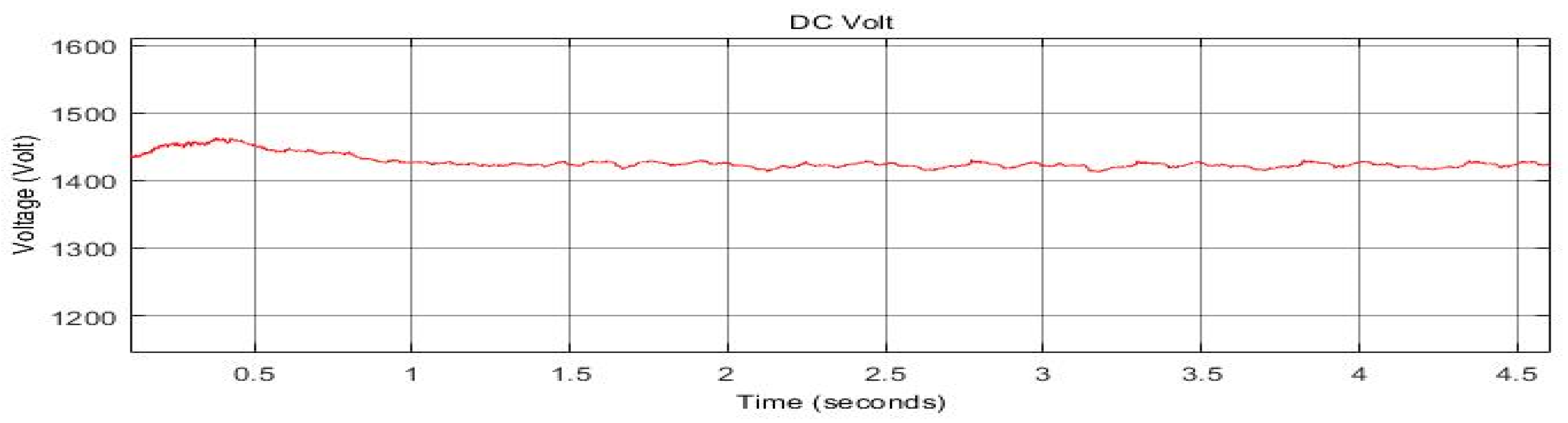
We can see that the current is stable during all simulations, and the THD is about 4.1%. Figure 15 shows the DC source voltage.
6.1.2. Using PWM Technique
Figure 16 shows the voltage wave for the load and grid when we use PWM.
Figure 17 shows the grid-side voltage and load-side amplitude during the simulation.
The voltage on the grid side has a THD between 6 and 8%, but on the load side, the THD does pass 5% during different operating conditions. Figure 18 shows the load current and THD using PWM.
We can see that the current is stable during all simulations, and the THD is about 4.5%. Figure 18 shows the DC source voltage.
6.2. Non-Linear Load on Load Side
The full simulation for this system is illustrated in Figure 19.
6.2.1. Using Hysteresis Technique
Figure 20 shows the grid-side voltage and load side when there is a non-linear load injecting harmonics on the grid.
Figure 21 shows the grid-side voltage and load-side amplitude during the simulation.
The voltage on the grid side has a THD between 4 and 6 %, but on the load side, the THD does not pass 5% during different operating conditions. The main purpose of using the UPQC is to keep electrical feeding for the load with high quality. We use a 250 KW load with 5 KVR as a sensitive load, and Figure 22 shows the load current and THD using hysteresis. That non-linear load in parallel does not affect the sensitive load. The THD is equal to 4.55% using a hysteresis band.
Figure 23 shows the DC source voltage.
6.2.2. Using PWM Technique
Figure 24 shows the voltage wave for the load and grid when we use PWM.
Figure 25 shows the grid-side voltage and load-side amplitude during the simulation.
We can see that the voltage on the grid side has a THD between 4.5 and 7.5%, but on the load side, the THD passes 4.8% during different operating conditions. Figure 26 shows the load current and THD using PWM.
We can see that the current is stable during all simulations, and the THD is about 4.5%.
7. Results Discussion
A UPQC is used to deliver electrical power to loads with high quality and without interruptions. The results can be divided into four sections to be discussed:
- Voltage amplitude
There are many parameters that affect the voltage amplitude, such as the change in the generated power from wind turbines, faults, load nature, and its value. Most standard emphases require a 5% variation in voltage amplitude at the distribution level. It is clear that the voltage amplitude on the load side is constant in all cases with two different pulsing techniques, despite the changes in the grid side, as we can see from the results figures when the fault happened. Additionally, removing it as a transit state in the system did not affect voltage amplitude.
- 2.
- Voltage THD
Voltage harmonics usually come from the grid side to the load, and we can see that in the first case of the non-linear load, where the THD on the grid side was high, the UPQC should have lowered the THD by injecting the same amount of voltage harmonics at the PCC. As we know, the THD is a very important parameter in determining power quality. We used the THD as a point of compression between different control techniques. Table 2 shows compression among the results of different cases of simulation when the non-linear load is on the grid side or the load side.
Table 3 shows the compression of the proposed method compared with the papers in the literature review for the voltage THD.
- 3.
- Current THD
Current harmonics essentially come from non-linear loads and go toward other near loads or utility grids. The shunt part of the UPQC is responsible for illuminating these harmonics before it goes into the system. The injected harmonics from the non-linear load should be illuminated by the UPQC, no matter where the non-linear load is connected. Table 4 shows the load current THD in different simulation cases.
Table 5 shows the compression of the proposed method with the papers in the literature review for the current THD.
- 4.
- DC Link voltage
Using an independent voltage source is important, because if we use a rectified voltage from the grid, the UPQC performance will be affected by the changes on the grid side. The proposed structure was able to regulate voltage in the DC link between the inverters to ensure power injection to the system. By using Clack’s transformations and a PI controller, the DC voltage was adjusted with 1PU under different compensating cases, which improved the UPQC total performance.
8. Conclusions
This paper proposes a DG system consisting of a wind turbine and a utility grid that feeds a sensitive load through the UPQC. The main goal was to improve power quality and voltage profile for the load under different operating conditions such as faults, non-linear loads, and variable generated power from the wind turbine in PCC. We then compared two methods based on the instantaneous power theory and PLL for pulse generation for electronic switches. Both of them were able to guarantee unlimited feeding power for the load with low THD values that did not pass 5%.
Future works could show how to improve the response of a UPQC by using artificial intelligence or expert systems instead of the PI controller. They could also show how to use optimization algorithms such as particle swarm PSO or genetic algorithms to choose the best location and size for a UPQC in DG.
Author Contributions
Conceptualization, G.G.; methodology, G.G. and D.I.M.; software, D.I.M.; validation, G.G.; formal analysis, G.G. and D.I.M.; investigation, G.G.; data curation, D.I.M.; writing—original draft preparation, G.G.; writing—review and editing, D.I.M.; visualization, G.G. and D.I.M.; supervision, G.G.; project administration, G.G. All authors have read and agreed to the published version of the manuscript.
Funding
This research received no external funding.
Institutional Review Board Statement
Not applicable.
Informed Consent Statement
Not applicable.
Data Availability Statement
I confirm that all data presented in this paper is available upon request from the authors.
Conflicts of Interest
The authors declare no conflict of interest.
Abbreviations
| UPQC | Unified power quality conditioner |
| PWM | Pulse-width modulation |
| PI | Proportional integral |
| PID | Proportional integral divertive |
| PCC | Point of common connection |
| PQ | Power quality |
| PLL | Phase-locked-loop |
References
- Lakshmi, G.S.; Rubanenko, O.; Divya, G.; Lavanya, V. Distribution energy generation using renewable energy sources. In Proceedings of the 2020 IEEE India Council International Subsections Conference (INDISCON), Virtual, 3–4 October 2020; pp. 108–113. [Google Scholar]
- Adeagbo, A.P.; Ariyo, F.K.; Makinde, K.A.; Salimon, S.A.; Adewuyi, O.B.; Akinde, O.K. Integration of Solar Photovoltaic Distributed Generators in Distribution Networks Based on Site’s Condition. Solar 2022, 2, 52–63. [Google Scholar] [CrossRef]
- Ganthia, B.P.; Barik, S.; Nayak, B. Application of hybrid facts devices in DFIG based wind energy system for LVRT capability enhancements. J. Mech. Cont. Math. Sci. 2020, 15, 245–256. [Google Scholar]
- Dhua, D.; Yang, G.; Zhang, Z.; Kocewiak, Ł.H.; Timofejevs, A. Harmonic active filtering and impedance-based stability analysis in offshore wind power plants. In Proceedings of the 16th Wind Integration Workshop, Hague, The Netherlands, 12–14 October 2017; pp. 1–8. [Google Scholar]
- Pinto, A.C.; dos Santos Neto, P.J.; Pereira, F.C. Passive Filters Applied to a Small Wind Turbine Based System. IEEE Lat. Am. Trans. 2016, 14, 3291–3298. [Google Scholar] [CrossRef]
- Hasan, K.M.; Rauma, K.; Luna, A.; Candela, J.I.; Rodriguez, P. Harmonic resonance damping in wind power plant. In Proceedings of the 2012 IEEE Energy Conversion Congress and Exposition (ECCE), Raleigh, NC, USA, 15–20 September 2012; pp. 2067–2074. [Google Scholar]
- Singh, A.; Baredar, P. Power quality analysis of shunt active power filter based on renewable energy source. In Proceedings of the 2014 International Conference on Advances in Engineering & Technology Research (ICAETR-2014), Kanpur, India, 1–2 August 2014; pp. 1–5. [Google Scholar]
- Ramya, P.; Arpitha, C.N. Reduction of THD in power system using generalized UPQC. Int. J. Electr. Electron. Eng. Telecommun. 2013, 4, 47–56. [Google Scholar]
- Matlani, D.M.; Solanki, M.D. UPQC: An Exhaustive Solution to Improve Power Quality. In Proceedings of the 2020 4th International Conference on Electronics, Communication and Aerospace Technology (ICECA), Coimbatore, India, 5–7 November 2020; pp. 416–421. [Google Scholar]
- Gupta, A.; Rai, V. Integration of Unified Power Quality Conditioner (Upqc) With Smart Grid. Int. J. LNCT 2020, 4, 6–15. [Google Scholar]
- Karelia, N.D.; Pandya, V.J. Distributed generation and role of upqc–dg in meeting power quality criteria–a review. Procedia Technol. 2015, 21, 520–525. [Google Scholar] [CrossRef]
- Kumar, C.P.; Pragaspathy, S.; Karthikeyan, V.; Prakash, K.D. Power quality improvement for a hybrid renewable farm using UPQC. In Proceedings of the 2021 International Conference on Artificial Intelligence and Smart Systems (ICAIS), Coimbatore, India, 25–27 March 2021; pp. 1483–1488. [Google Scholar]
- Kesler, M.; Ozdemir, E. Synchronous-reference-frame-based control method for UPQC under unbalanced and distorted load conditions. IEEE Trans. Ind. Electron. 2010, 58, 3967–3975. [Google Scholar] [CrossRef]
- Rajarajan, R.; Prakash, R. Mitigation of voltage sags and stability analysis of distribution system based on upqc using substantial transformation intrinsic algorithm (STIA). J. Crit. Rev. 2019, 7, 2020. [Google Scholar]
- Reddy, C.R.; Goud, B.S.; Aymen, F.; Rao, G.S.; Bortoni, E.C. Power quality improvement in HRES grid connected system with FOPID based atom search optimization technique. Energies 2021, 14, 5812. [Google Scholar] [CrossRef]
- Szromba, A. The unified power quality conditioner control method based on the equivalent conductance signals of the compensated Load. Energies 2020, 13, 6298. [Google Scholar] [CrossRef]
- Patnaik, N.; Pandey, R.; Satish, R.; Surakasi, B.; Abdelaziz, A.Y.; El-Shahat, A. Single-Phase Universal Power Compensator with an Equal VAR Sharing Approach. Energies 2022, 15, 3769. [Google Scholar] [CrossRef]
- Hussain, J.; Hussain, M.; Raza, S.; Siddique, M. Power quality improvement of grid connected wind energy system using DSTATCOM-BESS. Int. J. Renew. Energy Res. 2019, 9, 1388–1397. [Google Scholar]
- Kenjrawy, H.; Makdisie, C.; Houssamo, I.; Mohammed, N. New Modulation Technique in Smart Grid Interfaced Multilevel UPQC-PV Controlled via Fuzzy Logic Controller. Electronics 2022, 11, 919. [Google Scholar] [CrossRef]
- Bouzelata, Y.; Kurt, E.; Chenni, R.; Altın, N. Design and simulation of a unified power quality conditioner fed by solar energy. Int. J. Hydrog. Energy 2015, 40, 15267–15277. [Google Scholar] [CrossRef]
- Muhammad, F.; Rasheed, H.; Ali, I.; Alroobaea, R.; Binmahfoudh, A. Design and Control of Modular Multilevel Converter for Voltage Sag Mitigation. Energies 2022, 15, 1681. [Google Scholar] [CrossRef]
- Goud, B.S.; Reddy, C.R.; Bajaj, M.; Elattar, E.E.; Kamel, S. Power Quality Improvement Using Distributed Power Flow Controller with BWO-Based FOPID Controller. Sustainability 2021, 13, 11194. [Google Scholar] [CrossRef]
- Raju, G.J. Hysteresis Control of a Unified Power Quality Conditioner for Current And Voltage Perturbations Compensation In A Power Distribution Network. Int. J. Eng. Res. Technol. 2013, 2, 2010–2015. [Google Scholar]
- Muthuvel, K.; Vijayakumar MSolar, P.V. sustained quasi Z-source network-based unified power quality conditioner for enhancement of power quality. Energies 2020, 13, 2657. [Google Scholar] [CrossRef]
- Remigio-Carmona, P.; González-de-la-Rosa, J.J.; Florencias-Oliveros, O.; Sierra-Fernández, J.M.; Fernández-Morales, J.; Espinosa-Gavira, M.J.; Palomares-Salas, J.C. Current Status and Future Trends of Power Quality Analysis. Energies 2022, 15, 2328. [Google Scholar] [CrossRef]
- Reddy, C.R.; Reddy, A.S.; Kumar, C.N.; Ahmed, M.I.; Reddy, D.R.; Goud, B.S.; Aymen, F. Power Quality Improvement in Integrated System using Inductive UPQC. Int. J. Renew. Energy Res. 2021, 11, 566–576. [Google Scholar]
- Kalla, U.K.; Kaushik, H.; Singh, B.; Kumar, S. Adaptive control of voltage source converter based scheme for power quality improved grid-interactive solar PV–battery system. IEEE Trans. Ind. Appl. 2019, 56, 787–799. [Google Scholar] [CrossRef]
- Bueno-Contreras, H.; Ramos, G.A.; Costa-Castelló, R. Power Quality Improvement through a UPQC and a Resonant Observer-Based MIMO Control Strategy. Energies 2021, 14, 6938. [Google Scholar] [CrossRef]
- Yousuf, S.M.; Arthi, S. Reactive Power Improvement in Wind Farm by Using UPQC. Int. J. Sci. Res. 2014, 3, 403–408. [Google Scholar]
- Farias, M.F.; Battaiotto, P.E.; Cendoya, M.G. Wind farm to weak-grid connection using UPQC custom power device. In Proceedings of the 2010 IEEE International Conference on Industrial Technology, Viña del Mar, Chile, 4–17 March 2010; pp. 1745–1750. [Google Scholar]
- Viji, A.J.; Balasubramaniyan, D.S. Comparative Analysis of UPQC With Various Hysteresis Current Controllers. Int. J. Electr. Eng. Technol. 2020, 11, 392–403. [Google Scholar] [CrossRef]
- Modesto, R.A.; da Silva, S.A.O.; de Oliveira, A.A.; Bacon, V.D. A versatile unified power quality conditioner applied to three-phase four-wire distribution systems using a dual control strategy. IEEE Trans. Power Electron. 2015, 31, 5503–5514. [Google Scholar] [CrossRef]
Figure 1.
UPQC structure.

Figure 2.
Series inverter with LC filter.

Figure 3.
DC link rectifier.

Figure 4.
Series inverter controller simulation.

Figure 5.
Shunt inverter controller simulation.

Figure 6.
DC voltage rectifier controller simulation.

Figure 7.
Hysteresis technique for pulsing modeling.

Figure 8.
PWM with PI controller technique for pulsing.

Figure 9.
Wind speed.

Figure 10.
Generated power from the wind turbine.

Figure 11.
The full simulation for the system (non-linear load on the grid side).

Figure 12.
Load-side voltage and grid-side voltage with non-linear load on the grid side using hysteresis.
Figure 12.
Load-side voltage and grid-side voltage with non-linear load on the grid side using hysteresis.

Figure 13.
Load-side voltage and grid-side voltage amplitude with non-linear load on the grid side using hysteresis.
Figure 13.
Load-side voltage and grid-side voltage amplitude with non-linear load on the grid side using hysteresis.

Figure 14.
Load current and THD during simulation with non-linear load on the grid side using hysteresis.
Figure 14.
Load current and THD during simulation with non-linear load on the grid side using hysteresis.

Figure 15.
DC source voltage.

Figure 16.
Load-side voltage and grid-side voltage with non-linear load on the grid side using PWM.

Figure 17.
Load-side voltage and grid-side voltage amplitude with non-linear load on the grid side using PWM.
Figure 17.
Load-side voltage and grid-side voltage amplitude with non-linear load on the grid side using PWM.

Figure 18.
Load current and THD during simulation non-linear load on the grid side using PWM.

Figure 19.
The full simulation for the system (non-linear load on the load side).

Figure 20.
Load-side voltage and grid-side voltage with non-linear load on the load side using hysteresis.
Figure 20.
Load-side voltage and grid-side voltage with non-linear load on the load side using hysteresis.

Figure 21.
Load-side voltage and grid-side voltage amplitude with non-linear load on the load side using hysteresis.
Figure 21.
Load-side voltage and grid-side voltage amplitude with non-linear load on the load side using hysteresis.

Figure 22.
Load current and THD during simulation non-linear load on the load side using hysteresis.
Figure 22.
Load current and THD during simulation non-linear load on the load side using hysteresis.

Figure 23.
DC source voltage.

Figure 24.
Load-side and grid-side voltage with non-linear load on the load side using PWM.

Figure 25.
Load-side voltage and grid-side voltage amplitude with non-linear load on the load side using PWM.
Figure 25.
Load-side voltage and grid-side voltage amplitude with non-linear load on the load side using PWM.

Figure 26.
Load current and THD during simulation non-linear load on the load side using PWM.


Table 1.
Power quality problems related to DG systems.
| Power Quality Problems | Wind | Solar | Hydro | Diesel |
|---|---|---|---|---|
| Current Harmonics | x | x | x | |
| Voltage Sag/swell | x | x | ||
| Voltage Harmonics | x | x | x | |
| Flicker | x | x | x | |
| Voltage Unbalance | x | |||
| Over/Under voltage | x | x | ||
| Interruption | x | x | ||
| Voltage Transient | x |
Table 2.
Results compression for voltage THD.
| Case | THD% on Grid Side | THD% on Load Side | |
|---|---|---|---|
| Non-linear load on grid side | Hysteresis | 8–10 | 4.9 |
| PWM | 6–8 | 4.9 | |
| Non-linear load on load side | Hysteresis | 4–6 | 4.8 |
| PWM | 4.5–7.5 | 4.8 |
Table 3.
Results compression for voltage THD with other papers.
| Research Number | Voltage THD% | Comment |
|---|---|---|
| Proposed method | 4.9 | 150 KW grid-connected WT with non-linear load, variable wind speed, and phase to ground fault |
| [5] | 5.84 | Passive filter with variable wind speed |
| [13] | 4.5 | under unbalanced load and without RES |
| [14] | 10.3 | PI controller |
| [14] | 7.5 | PID controller |
Table 4.
Results compression for current THD.
| Case | THD% on Load Side Current | |
|---|---|---|
| Non-linear load on grid side | Hysteresis | 4.1 |
| PWM | 4.5 | |
| Non-linear load on load side | Hysteresis | 4.55 |
| PWM | 4.5 |
Table 5.
Results compression for current THD with other papers.
| Research Number | Current THD% | Comment |
|---|---|---|
| Proposed method | 4.55 | 150 KW grid-connected WT with non-linear load, variable wind speed, and phase to ground fault |
| [4] | 7.44 | Four grid-connected wind turbines |
| [4] | 15.95 | One grid-connected wind turbine |
| [5] | 11.42 | Passive filter with variable wind speed |
| [7] | 4.85 | Using fuzzy logic controller |
| [8] | 3.54 | With 60 W PV panel |
| [13] | 3.5 | Single-phase system that is connected to the utility grid. |
Publisher’s Note: MDPI stays neutral with regard to jurisdictional claims in published maps and institutional affiliations. |
© 2022 by the authors. Licensee MDPI, Basel, Switzerland. This article is an open access article distributed under the terms and conditions of the Creative Commons Attribution (CC BY) license (https://creativecommons.org/licenses/by/4.0/).
Share and Cite
MDPI and ACS Style
Mahdi, D.I.; Gorel, G. Design and Control of Three-Phase Power System with Wind Power Using Unified Power Quality Conditioner. Energies 2022, 15, 7074. https://doi.org/10.3390/en15197074
AMA Style
Mahdi DI, Gorel G. Design and Control of Three-Phase Power System with Wind Power Using Unified Power Quality Conditioner. Energies. 2022; 15(19):7074. https://doi.org/10.3390/en15197074
Chicago/Turabian StyleMahdi, Dheyaa Ied, and Goksu Gorel. 2022. "Design and Control of Three-Phase Power System with Wind Power Using Unified Power Quality Conditioner" Energies 15, no. 19: 7074. https://doi.org/10.3390/en15197074
Note that from the first issue of 2016, this journal uses article numbers instead of page numbers. See further details here.