
Development of Ultra-Low Specific Speed Centrifugal Pumps Design Method for Small Liquid Rocket Engines

1
Department of Aerospace Engineering, Inha University, 36 Gaetbeol-ro, Yeonsu-gu, Incheon 21999, Korea
2
Department of Aerospace Engineering, Chungnam National University, 99 Daehak-ro, Yuseong-gu, Daejeon 34134, Korea
*
Author to whom correspondence should be addressed.
Aerospace 2022, 9(9), 477; https://doi.org/10.3390/aerospace9090477
Submission received: 11 July 2022
/
Revised: 15 August 2022
/
Accepted: 24 August 2022
/
Published: 28 August 2022
(This article belongs to the Special Issue Liquid Rocket Engines)
Abstract
:With the growth of the satellite industry, the demand for a propulsion system for small launch vehicles and spacecraft has increased. Small liquid rocket engines may require Ultra-Low specific speed centrifugal pumps due to the low required thrust and volumetric flow rate and high combustion chamber pressure. Therefore, in this study, a design method of Ultra-Low specific speed centrifugal pumps for several hundred Newton class small liquid rocket engines was developed by combining various empirical formulas. In addition, centrifugal pump impellers were designed using the Stepanoff method, which is typically used in pump design, and the circular arc method. The most appropriate method for designing Ultra-Low specific speed centrifugal pumps was determined through a comparative analysis with other methods and validated through CFD. As a result, the pump designed using the proposed method exhibited a performance of pumping and suction superior to the Stepanoff method. Although the number of arcs did not considerably influence the pump performance, the single arc method was confirmed to be the most appropriate design approach in terms of the design productivity and simplicity.
1. Introduction
Liquid rocket engines can be divided into pressure-fed, turbopump-fed, and electric-pump-fed cycle engines according to the method by which the liquid propellants in the tank are supplied to the combustion chamber. In pressure-fed engines, the internal pressure of the tank can be increased with the operation time, leading to an increase in the engine weight. To address this problem, modern liquid rocket engines are based on turbopump and electric-pump-fed cycles in which centrifugal pumps are used to pressurize the propellant and supply them to the combustion chamber. Unlike low-head commercial pumps, primarily intended for pumping or transportation, the pump in a liquid rocket engine is designed to pressurize the liquid propellant and supply the required mass flow rate to the combustor, which necessitates a large head and renders the design of centrifugal pumps challenging [1]. In the initial design stage of the pumps, the volumetric flow rate and head are determined considering the operating objective of the pump, and the pump rotational speed is determined based on the pump size and driving performance. In general, a specific speed is used in pump design, determined based on the required volumetric flow rate, head, and rotational speed limit. The specific speed is typically calculated considering the properties at the design point, which corresponds to the maximum efficiency, and can be used to identify the optimal pump type. Consequently, methods based on the specific speed have been established for designing the optimal pump shape [1,2,3,4,5]. The Stepanoff method is commonly used to design pumps with a specific speed ranging from 10 to 300 in SI units [5]. Because a liquid rocket engine for a typical space launch vehicle requires a high thrust, a centrifugal pump—typically with a specific speed of 10–80 in SI units—is used to pressurize the propellant to achieve a high volumetric flow rate. For example, the oxidant centrifugal pump of a J-2 engine with a thrust of 486.2 kN has a specific speed of 25, and the fuel and oxidant centrifugal pumps of an F-1 engine with a thrust of 6770 kN have a specific speed of 21, and 44, respectively [6].
With the growth of the small satellite industry in recent years, the development of small launch vehicles and spacecraft propulsion has been accelerated [7,8,9]. If the engine size is small, propellant centrifugal pumps with a low mass flow rate and high head may be required. The specific speed associated with operating points involving a low volumetric flow rate and a high head is 10 or less, and the corresponding pumps are known as Ultra-Low specific speed centrifugal pumps. Ultra-Low specific speed centrifugal pumps are out of the range of general specific speed centrifugal pumps. Notably, as the specific speed decreases, the efficiency of the centrifugal pump decreases [5]. Thus, Ultra-Low specific speed centrifugal pumps are difficult to be designed using techniques pertaining to commercial centrifugal pumps. In general, a multi-stage centrifugal pump that connects and pressurizes multiple general specific speed impellers in series can be used instead of an Ultra-Low specific speed centrifugal pump. However, in the case of small liquid rocket engines, the use of a single-stage centrifugal pump with an Ultra-Low specific speed is desirable considering the light weight.
The design methods for centrifugal pumps have been extensively studied based on the component configurations. Many researchers have examined the relationship between the impeller and volute configurations and centrifugal pump performance in a general specific speed range [10,11,12,13,14,15,16,17,18]. In addition, because the pump shape is closely related to the performance, studies have been made to optimize the shape to enhance the pump performance [19,20,21,22,23,24]. Meanwhile, the centrifugal pump design using the empirical method, which has a low analysis cost and can obtain design results quickly, was also carried out [25,26]. Pak et al. developed a centrifugal pump design program to design the impeller and volute by using the Stepanoff method and validated the results by comparing the obtained design with commercial products [25]. Similarly, Lim et al. designed a centrifugal pump by using the Stepanoff method and validated the design using the secondary vortex panel method [26]. Liu et al. studied to optimize the design by comparing five impeller design methods that included empirical formulas and splitter attachment considerations [27]. Additionally, researchers have studied to understand the relationship between the shape and performance of Ultra-Low specific speed centrifugal pumps. Choung et al. performed numerical analysis for a centrifugal pump with a specific speed of 9.8 and noted that the number of blades did not considerably influence the performance of Ultra-Low specific speed centrifugal pumps [28]. Choi et al. reported that compared to a volute casing, a circular casing was preferable for Ultra-Low specific speed centrifugal pumps due to the smaller radial thrust and higher efficiency [29]. Some studies have also been performed on the Ultra-Low specific speed centrifugal pump design. Grunde et al. designed a centrifugal pump with a specific speed of 4.8 by using the Stepanoff method, changed the shape variable appropriately to decrease losses, and suggested the directions for centrifugal pump design based on the results of computational simulations [30]. Furthermore, the optimal design for the Ultra-Low specific speed centrifugal pump design was carried out. Wang et al. designed a centrifugal pump with a specific speed of 6.4 by using the two-dimensional (2D) design method based on the developed boundary layer theory [31], and Hou et al. performed an optimal design by entropy product method [32]. In both these studies, the performance enhancement was validated through computational simulations. Notably, the abovementioned studies focused on analyzing the influence of specific shape conditions on the performance of Ultra-Low specific speed centrifugal pumps. None of the previous studies have extensively examined the techniques and procedures for designing Ultra-Low specific speed centrifugal pumps. In the previous studies on centrifugal pump design techniques, the minimum specific speed was 15, which was focused on the general commercial centrifugal pump design, and research on the design techniques of Ultra-Low specific speed centrifugal pump of 10 or less is rather limited. A method for designing Ultra-Low specific speed centrifugal pumps that can pressurize a low mass flow rate and high head propellant as a single-stage micro centrifugal pump for use in ultra−small liquid rocket engines remains to be established.
As mentioned, most of the previous research to design centrifugal pumps was based on the Stepanoff method, which is applicable to the general specific speed range. The validity of applying the Stepanoff method for designing a system requiring an Ultra-Low specific speed centrifugal pump needs to be examined, and an appropriate method for designing Ultra-Low specific speed centrifugal pumps should be established. Therefore, this study was aimed at developing and validating a method for designing an Ultra-Low specific speed centrifugal pump for an ultra−small liquid rocket engine with a thrust of several hundred Newtons, using empirical formulas for the design variables. Especially for use in the early design stage that requires various cases, a design method that can derive quick results is necessary to develop, using empirical formulas for each design variable. The pressurization performance of the pump was evaluated through computational fluid dynamics (CFD) simulations to validate the proposed design technique. The performance of the pump designed using the proposed method was compared with those designed using the Stepanoff method and circular arc method to determine the appropriate technique for designing Ultra-Low specific speed micro centrifugal pumps.
2. Design of Ultra-Low Specific Speed Centrifugal Pump
2.1. Design Requirements for the Ultra-Low Specific Speed Centrifugal Pump
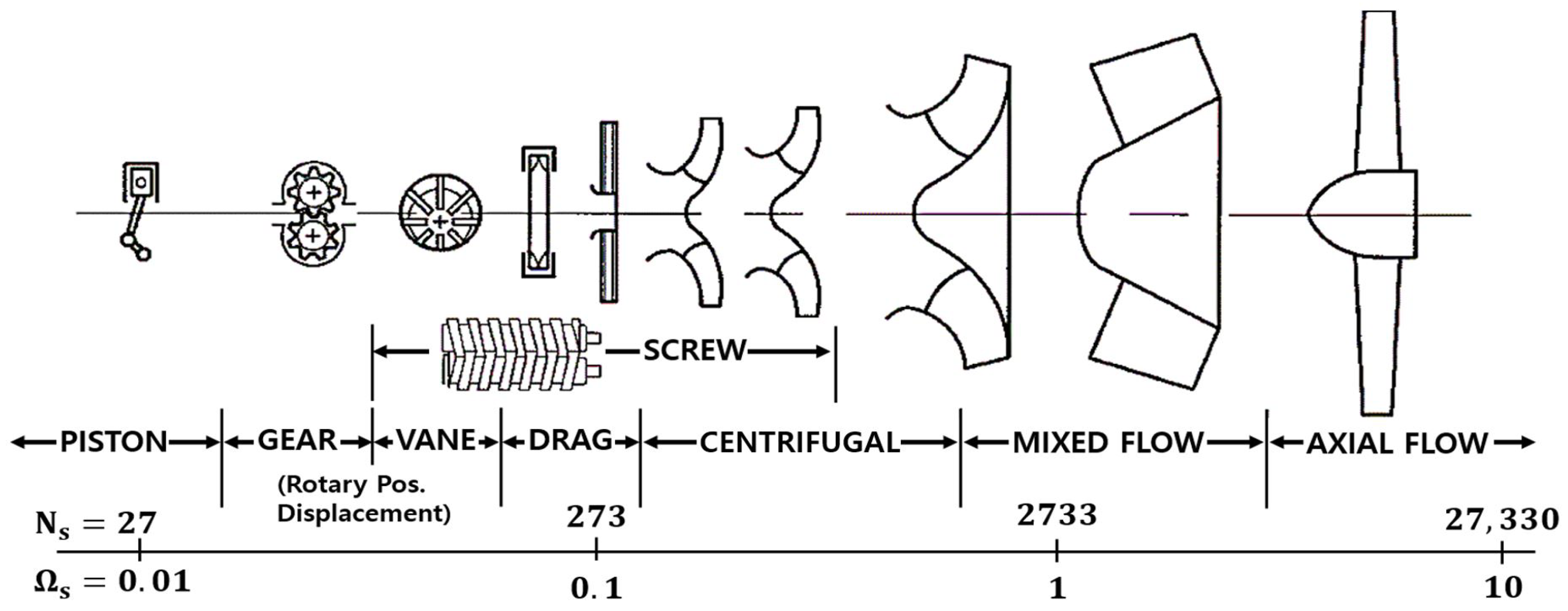
The volumetric flow rate, head, and rotational speed influence the pump performance and can be used to determine the specific speed of a pump. In other words, the specific speed is an indicator of the pump performance and can be used to predict the impeller shape such as centrifugal or axial flow type, as shown in Figure 1. The specific speed , as a key pump design factor, can be calculated using Equations (1) and (2) and expressed in SI or US units or as a dimensionless term .
The combustion chamber pressure for engines with a thrust of several hundred Newtons is typically between 0.7 and 2 MPa, and the combined range of the oxidant and fuel mass flow rates is 0.05–0.25 kg/s [33,34,35,36,37,38]. In this study, the goal was to find the appropriate design procedure and method for the centrifugal pumps for these engines, and thus, the design point corresponded to a low mass flow rate and high head conditions. The pump design requirements were set as follows: target pressure of 2,000,000 Pa, mass flow rate of 0.0628 kg/s, corresponding to volumetric flow rate of 1 gpm. To design and validate the Ultra-Low specific speed centrifugal pump, and considering only the shape design technique, the working fluid of the pump was set as water at 25 °C instead of a specific fuel, considering the similarity of the media. There have been several cases using water as a similar medium for pump design [39,40,41]. In particular, there are cases where the performance of the pump has been tested using kerosene and water, and according to the report, the hydraulic performance is known to be the same, but there was only difference in density with each medium [39]. In addition, the turbopump of a liquid rocket is a fully turbulence system in which the Reynolds effect remains relatively constant because it operates at high speed [40]. Accordingly, it is known that the similarity of the pump performance is preserved even if the Reynolds number according to the fluid is not perfectly scaled [40]. Thus, it has the advantage of being able to confirm the pump performance in advance using water before using the real medium. In this study, the head was determined to be 205 m by the working fluid and requirements. If a higher rotational speed is considered based on the design requirements, the specific speed will increase, facilitating the design, but it may be difficult to obtain an actual motor. A lower rotational speed may lead to an extremely low specific speed, and it is challenging to design by obtaining a physically impossible shape. Therefore, considering the availability of commercial motors and feasibility of design manufacturing, a rotational speed of 50,000 rpm was set. The specific speed based on the abovementioned requirements was seven in SI units, and thus, an Ultra-Low specific speed centrifugal pump was required to be designed.
2.2. Design Procedure of Ultra-Low Specific Speed Centrifugal Pump
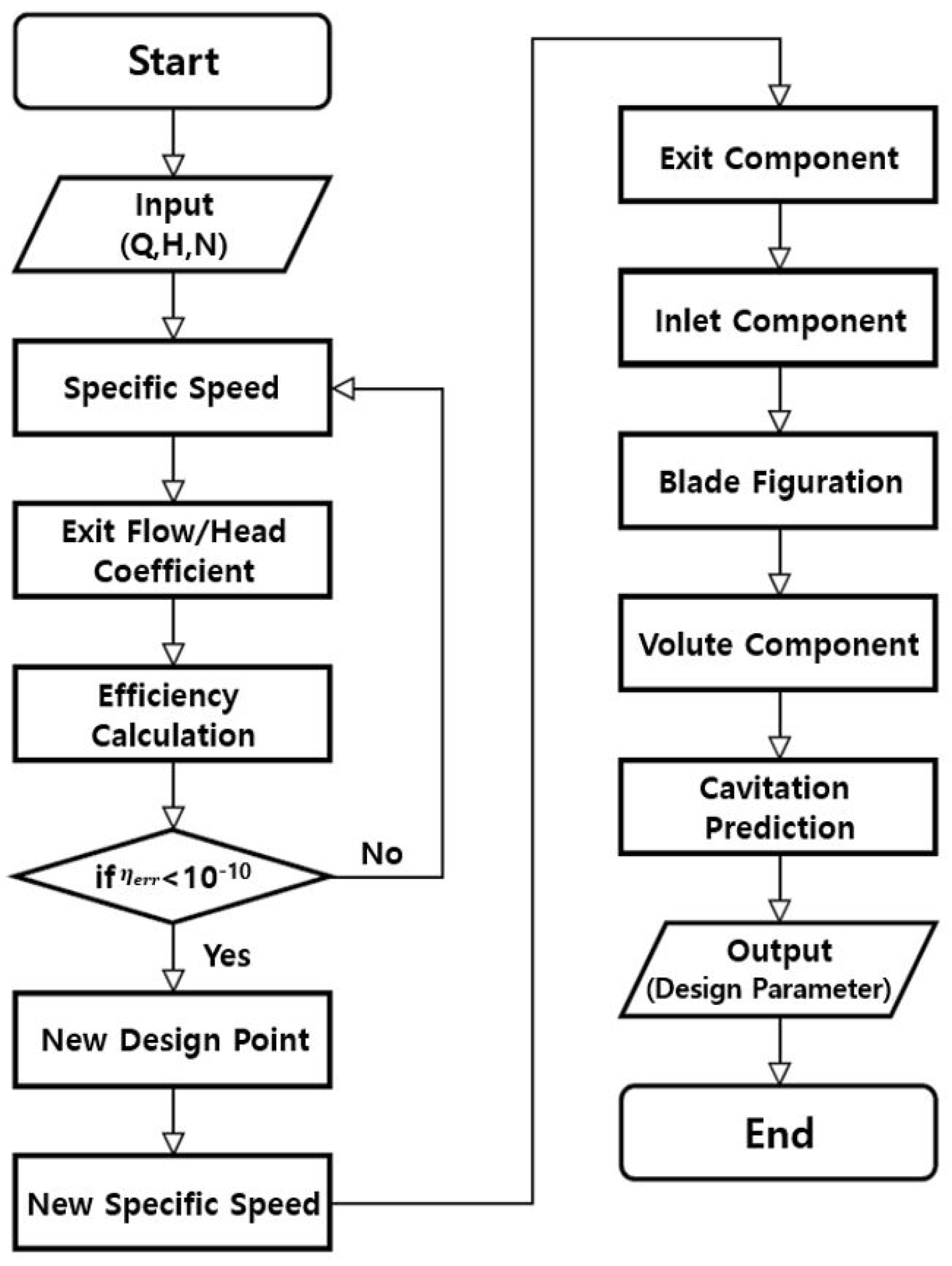
Figure 2 shows the design process flow of the Ultra-Low specific speed centrifugal pump. The pump is primarily composed of an impeller and a volute, and each of the two components should be designed considering shape variables. In the Stepanoff method, the impeller and volute are separately designed. The proposed design procedure and the Stepanoff method differ primarily in terms of the method used to design the impeller. Because the impeller influences the centrifugal pump performance more, this study focused on the impeller design, and thus, the volute was designed using the Stepanoff method. The specific speed was used to determine the initial exit head coefficient, flow coefficient, and diameter ratio of the inlet and outlet. The hydraulic and volumetric efficiency of the pump were calculated using Lomakin’s formula [2] and the equations presented in Igor Karassik’s Pump Handbook [1]. In the initial design stage, the target design point performance can be obtained when designing with the volumetric flow rate and head considering the losses. Therefore, the head and volumetric flow rate, considering the losses, were calculated using the determined efficiency values, and the overall efficiency of the designed pump was determined as the converged value in the iterative calculation. The pump was designed using the volumetric flow rate and head calculated using the final efficiency. Using the specific speed associated with the design point including the loss, the exit and inlet diameters were determined using the Cordier diagram [42] and Lobanoff’s formula [4], respectively. The number of blades was determined using Pfleiderer’s formula [43], and the blade thickness, inlet, and exit widths were calculated. The final exit angle was determined by supplementing the theoretical slip through Wiesner’s slip factor [44]. The diameter, width, and area of the volute were determined using the Stepanoff method [5], and all shape design values of the pump were derived.
2.3. Design Method of Centrifugal Pump with Ultra-Low Specific Speed
2.3.1. Determination of the Pump Efficiency
The pump efficiency includes the hydraulic efficiency, volumetric efficiency, mechanical efficiency, and total efficiency. The hydraulic efficiency and volumetric efficiency , related to the head and volumetric flow rate, respectively, can be considered in the initial conceptual design stage. The efficiency factors can be defined as in Equations (3) and (4). Various methods are available to predict each efficiency. For example, the volumetric efficiency can be determined using Equation (5), which is Lomakin’s empirical formula [2], and Equation (6), which is an approximation for the leakage of a closed-impeller pump with assuming orifice-type flow at a discharge coefficient of suggested by Stepanoff [1]. In this study, the average value of the efficiencies determined using these two expressions was used. The equation for calculating the hydraulic efficiency has been derived from various empirical formulas based on volumetric flow rates proposed by Jekat and Lomakin [1,2]. However, this method is challenging to apply because the volumetric flow rate for the centrifugal pump of a small liquid rocket engine is too low, and non-physical values may be derived when calculating the efficiency. Therefore, in this study, Equation (7) was used, in which the losses in the impeller and volute are defined as the head and flow coefficient. This equation is known to fit well, especially when no pre-swirl exists at the inlet [1]. Considering the definition of the efficiency factors, a theoretical head and volumetric flow rate that could compensate for the calculated loss were derived to obtain a new design point, and the final efficiencies and design point conditions, as the converged values in the iterative calculation were determined.
2.3.2. Impeller Exit
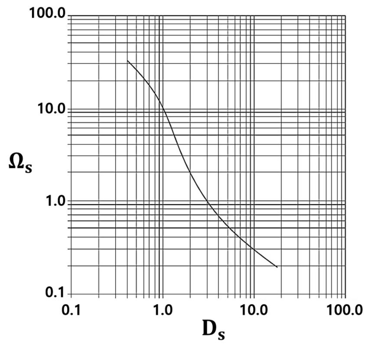
The head is considerably influenced by the exit diameter. In the previous studies, although the Stepanoff method was used to determine the impeller exit diameter, this method was validated in the specific speed range of about 10–300 in SI units [5]. The pump shape for the Ultra-Low specific speed range can be designed through extrapolation, but its accuracy cannot be guaranteed. Therefore, in this study, the impeller exit diameter was determined using the Cordier diagram [42,45], which has been empirically defined even in the Ultra-Low specific speed range. The Cordier diagram is defined the relationship between the specific diameter , expressed as in Equation (8), and the dimensionless specific speed . Using the Cordier diagram shown in Figure 3, the specific diameter was calculated from the dimensionless specific speed, and the impeller exit diameter was derived as the definition of the specific diameter. Next, the vertical velocity at the impeller exit was determined using Equation (9), which is the definition of the impeller exit flow coefficient, and Equation (10), which is expressed by dimensionless specific speed [1]. Finally, the absolute velocity tangential to the exit was calculated by using the Euler equation [3], and the impeller exit angle , exit final absolute velocity, and relative velocity components were determined using the velocity triangle.
2.3.3. Impeller Inlet
The diameter ratio of the inlet and outlet was determined using Lobanoff’s formula [4] as the derived specific speed in US units, and the inlet diameter was derived. In this study, the centrifugal pump without an inducer was targeted for engine light weight. However, without an inducer, the centrifugal pump inlet should serve as a suction part. Therefore, when determining the inlet flow coefficient , Equation (11) was used to determine the flow coefficient of the inducer [4]. Subsequently, the vertical velocity at the inlet was derived using Equation (12). In this study, it was assumed that there was no pre-swirl at the centrifugal pump inlet because the inducer was not considered. Iterative calculations were performed considering ° in the inlet velocity triangle as the inlet angle of the impeller to determine the absolute velocity and relative velocity components.
2.3.4. Blade
The number of blades was determined using Pfleiderer’s formula in Equation (13), which is commonly used [43]. The blade thickness was determined considering the design guidelines for rocket engine centrifugal pumps [46], requiring at least 80% of the circumferential area at the pump inlet to be a free area. The inlet width and the exit width of the blades, were derived using Equations (14) and (15) [1] based on the mass conservation law. In general, the exit width may decrease due to the development of the boundary layer caused by the interaction between the blade and flow. Because the efficiency decreases with decreasing exit width, the exit width is typically increased by introducing a contraction coefficient that ranges from 0.8 to 0.9. A smaller pump corresponds to a smaller coefficient [1]; therefore, in this study, the coefficient was set as 0.8, considering that the centrifugal pump designed in this study was micro size.
Because the centrifugal pump is a rotating fluid machine, a sliding phenomenon occurs in the blade. To consider this aspect, the final blade exit angle was determined by supplementing the theoretically possible exit sliding phenomenon in the initial design stage to compensate for this. Wiesner’s formula [44] was used to calculate the slip coefficient, considering the inlet and outlet diameter ratio. Slip means the decrease in the absolute exit velocity in the tangential direction, as indicated in Equation (16), and the slip coefficient was calculated by comparing the index value determined using Equation (17) and the diameter ratio of the inlet and exit, determined using Equation (18) [44]. The slip magnitude was determined using the calculated slip coefficient, and the final exit angle was determined considering the previously calculated exit angle and reduced angle. Using the updated outlet angle, the final number of blades and thickness were recalculated.
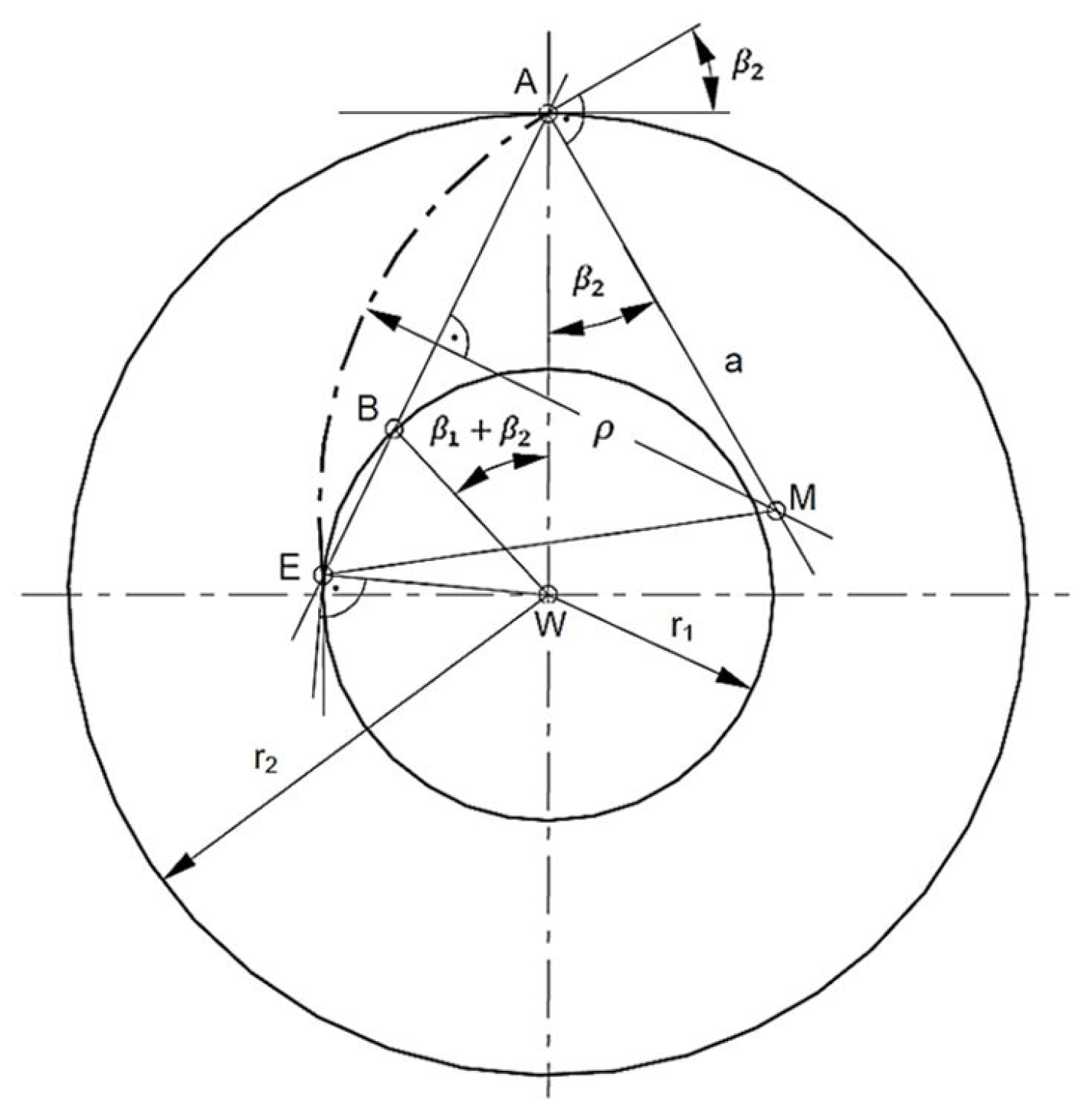
The curvature of the blade was determined using the circular arc method. The number of arcs in this approach is typically decided by the designer [47]. In this study, the single arc method, corresponding to the simplest design process with a satisfactory prediction performance, was used as the primary model [48]. In addition, the single arc method was compared with double and triple arcs methods to understand the performance change for the circular arc method. Figure 4 shows the single arc schematic for deriving the blade curvature. A two-dimensional blade shape can be determined considering the radius and angle of the impeller inlet and outlet. The blade curvature was derived using Equation (19) according to the geometric relationship [48].
2.3.5. Volute
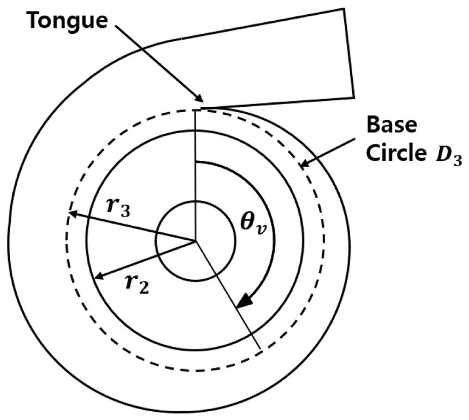
The volute collects the flow from the impeller. In the volute diffuser, the kinetic energy of the flow is converted to pressure without loss as much as possible to be sent to the outlet. It is known that the efficiency is maximized in the pump characteristics curve when the average flow velocity for each cross section of the flow path is constant [48]. In this study, the cross-sectional area was designed to obtain a constant average velocity by using the Stepanoff method for volute design [5]. The shape of the volute is shown in Figure 5. The cross-sectional area gradually increases, and the base circle diameter of the volute is determined by the circle of the part that meets the tongue of the volute. The volute was designed by determining the diameter of the base circle.
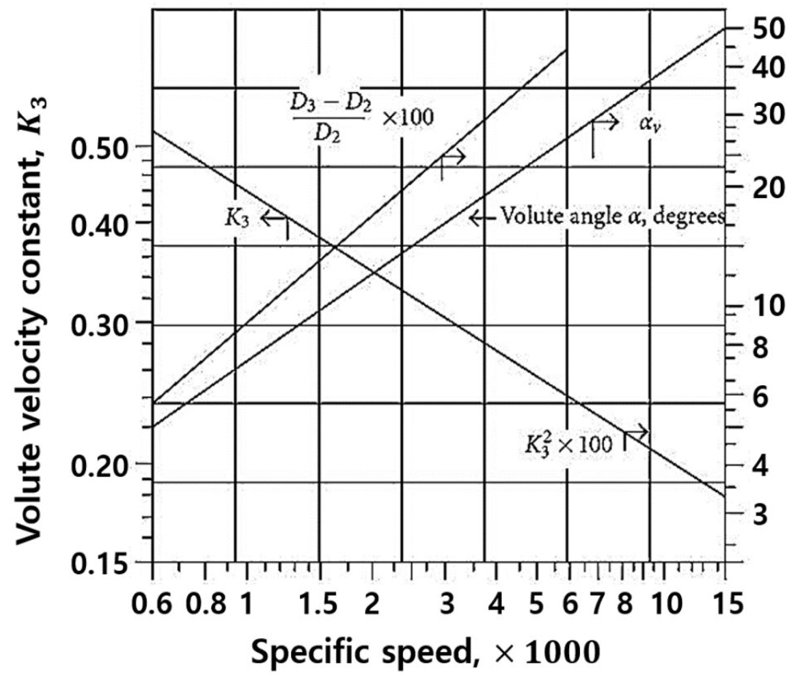
The base circle diameter was derived using the Stepanoff method for volute design [5], reflected in Equation (20) and Figure 6. The lack of a gap between the impeller exit diameter and volute may lead to noise generation or efficiency deterioration. Therefore, the base circle diameter was set larger than the impeller exit diameter [5]. The position of the volute tongue considerably influences the centrifugal pump performance. Therefore, the volute tongue was placed at 10° to 15°, which is reported to be the most suitable position based on the value of in Figure 5 [18,49]. To obtain the average velocity in the volute, the flow coefficient was calculated using the specific speed in US units, as shown in Figure 6 and Equation (21). The throat cross-sectional area was determined using the average velocity, as indicated in Equation (22), and the cross-sectional area at each angle was determined in 45° intervals in proportion to the volute throat cross section. The cross section of the volute was modeled to be circular, using the determined cross-sectional area.
2.3.6. Prevention of Centrifugal Pump Cavitation
Cavitation is a significant problem that can occur during centrifugal pump operation when pressure is lower than the vapor pressure of the fluid. Cavitation can influence the thrust by causing flow instabilities and pump performance deterioration and must thus be prevented through appropriate design. The condition of the suction flow considerably influences the occurrence of cavitation. The suction conditions are determined by the available net positive suction head(NPSHa) and required net positive suction head (NPSHr). The NPSHa indicates the head required for the centrifugal pump to operate smoothly, calculated as the between the centrifugal pump inlet pressure and vapor pressure. The value of this parameter depends on the system in which the centrifugal pump is installed. The NPSHr indicates the head corresponding to the pressure drop that occurs before the liquid entering the impeller is pressurized, which is the unique value of the centrifugal pump. Because cavitation occurs when NPSHr is greater than NPSHa, NPSHa is generally set to be >1.3 NPSHr considering the margin [2]. In this study, the NPSHr was determined using the NPSHr prediction graph [2] considering the peripheral velocity and suction inlet velocity determined by the inlet specifications. The NPSHr was used to determine the appropriate NPSHa at which cavitation does not occur, and the pressure of the suction part at the centrifugal pump inlet was determined according to the definition of NPSHa [2].
2.4. Design Result of Centrifugal Pump with Ultra-Low Specific Speed
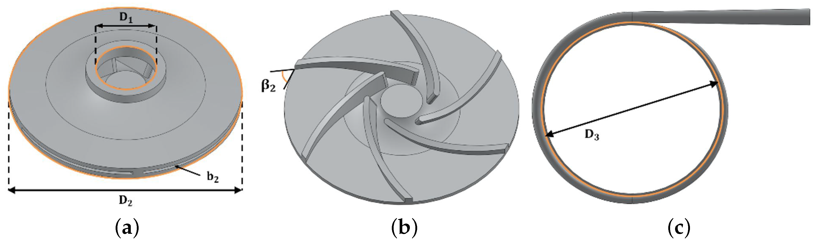
The centrifugal pump design technique described in Section 2.3 is a method that applies the most appropriate design technique for each component based on various previous studies. A centrifugal pump satisfying the requirements was designed considering the Ultra-Low specific speed design. The inlet and exit diameters, angles, and widths of the impeller satisfying the volumetric flow rate, head, and rotational speed were determined. Next, the blade shape parameters such as the number of blades, thickness, curvature, and volute shape were designed. The Ultra-Low specific speed centrifugal pump was designed for small liquid rocket engines with a thrust of several hundred Newtons with extreme operational conditions, considering a mass flow rate of 0.0628 kg/s, head of 205 m, and rotational speed of 50,000 rpm. The designed centrifugal pump was a small single-stage pump with a volute, appropriate for a small liquid rocket engine. The pump impeller shape is shown in Figure 7, and the geometric specifications are summarized in Table 1.
3. Validation of Design Method through CFD Simulations
3.1. Numerical Approach
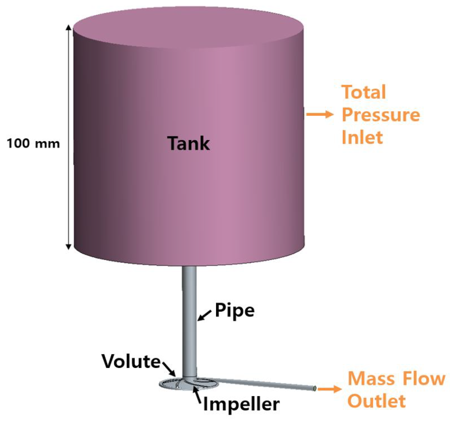
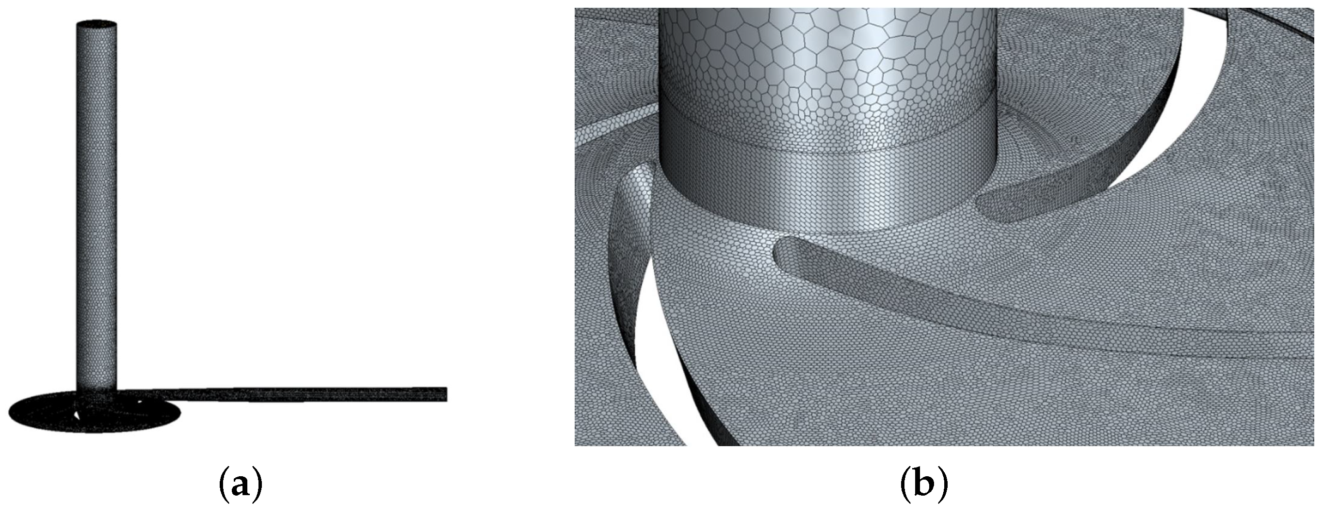
The commercial CFD program, Star-CCM+ 2021.1, was used.A three-dimensional RANS(Reynolds-averaged Navier–Stokes equations) analysis was conducted to validate the performance of the designed centrifugal pump for a steady-state incompressible flow. A pressure-based segregated solver was applied, and MUSCL (Monotonic Upwind Scheme for Conservation Laws) was used for the convection. The shear stress transport model, which is commonly used in the analysis of rotating fluid machines, was applied as the turbulence model, and the residuals of all equations converged to 10 or less. The working fluid was water at a temperature of 25 °C, a density of 997.561 kg/m, and a viscosity of 8.8871 × 10 Pa-s. The MRF(Moving Reference Frame) method was used to simulate the rotation of the centrifugal pump. When the MRF technique is used, the impeller area does not rotate, but only the effect of rotating due to the influence of the rotational coordinate system and centrifugal force is considered; thus, the result may vary with the blade position. Considering this aspect, the volute tongue was placed in the center of each blade to evaluate the average performance of the centrifugal pump. The analysis domain consisted of a tank, suction pipe at the centrifugal pump inlet, and discharge pipe at the volute outlet to simulate the operating condition of the impeller, volute, and actual centrifugal pump, as shown in Figure 8. The tank was included in the analysis domain because the liquid rocket engine supplied the propellant. Furthermore, the inlet pipe length was set as 10 times its diameter considering actual operational requirement, and the outlet pipe length was set to be 15 times its diameter to make it a fully developed flow. The suction pipe and volute were set to a fixed frame, and a rotating frame of 50,000 rpm was applied only to the impeller to simulate the pump rotation. The pump performance at the design point was validated by applying the mass flow rate at the outlet, and a total pressure of 350,000 Pa at the inlet, considering the NPSHa to prevent cavitation and the propellant tank pressure. Although the CFD simulation results were not compared with the experimental results, the numerical method applied in the present study is the same as in several previous studies for performing flow analysis in the pump [50,51,52]. In addition, the results show that the CFD results are similar to the theoretical values.
A polyhedral grid was applied, and fine grids were generated near the wall such that the y+ value of the wall grid approached 1 through a prism layer, suitable for the considered turbulence model. Moreover, a fine grid was applied to the impeller and volute, with grid sizes determined through grid dependency. According to the grid dependency test at the volumetric flow rate designed considering the requirements, the head increase with the grid size and then became constant, as indicated in Table 2. Therefore, the appropriate grid size was 0.1 mm, and the total number of grids was 2,717,280. Figure 9 shows the grid of the domain and the impeller.
3.2. Performance Validation of the Designed Centrifugal Pump
Because a liquid rocket engine pump must supply the propellant to the combustion chamber at a high pressure, the pressurizing capacity of the centrifugal pump is a key performance indicator. Therefore, the proposed design method was validated considering the head performance of the centrifugal pump at a design point. The head can be defined using Equation (23), based on the difference between the centrifugal pump impeller inlet pressure and volute outlet pressure when the propellant passes through the impeller. In this study, the head was derived as the average surface pressure at the impeller inlet and volute outlet, obtained from computational simulations. In addition, the overall efficiency of the pump was calculated by deriving the head and torque of the design pump through numerical results and substituting these values into Equation (24).
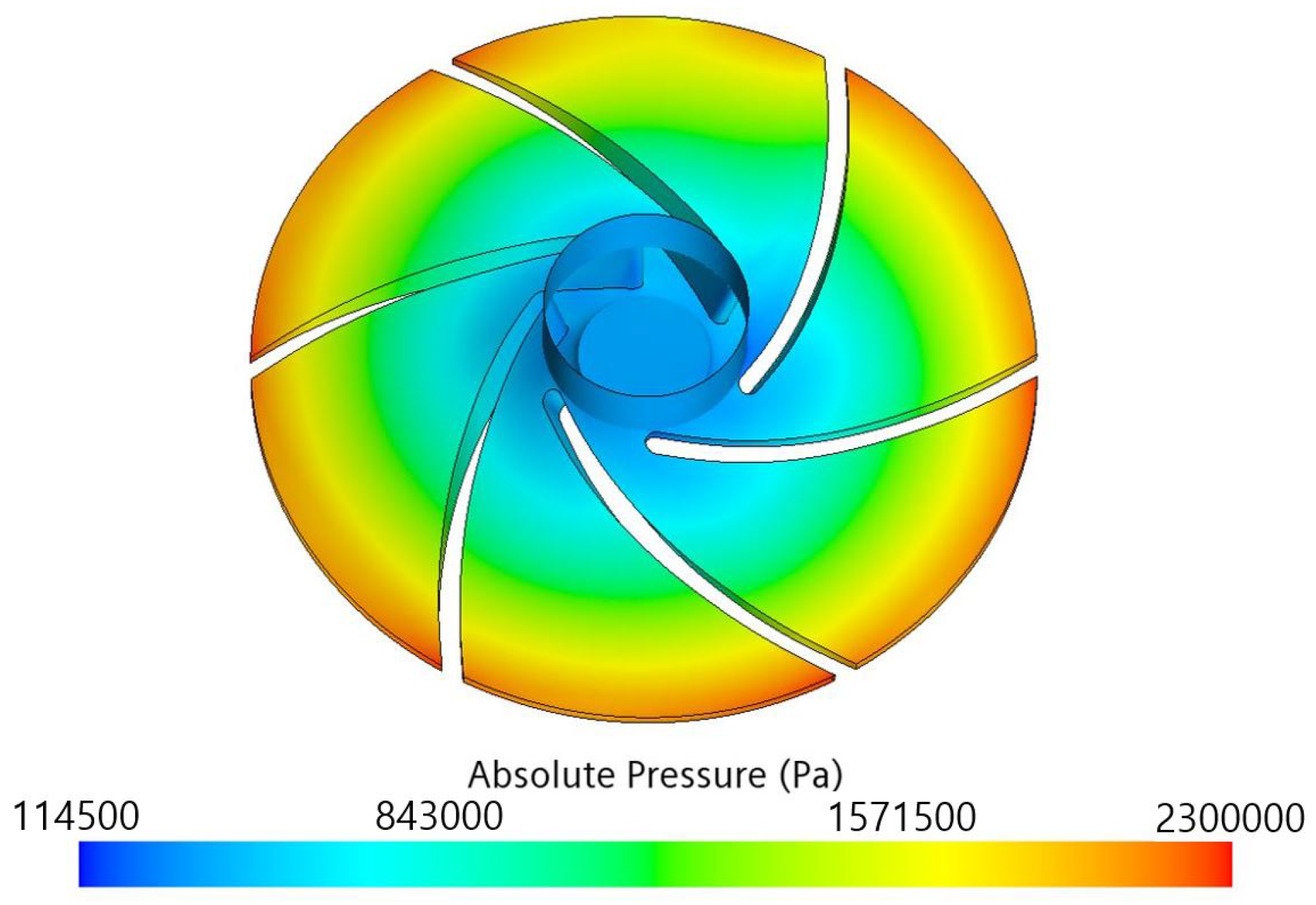
The centrifugal pump designed using the proposed method could pressurize to 2,126,000 Pa, and the head was 217.25 m, 5.98% higher than the design point of 205 m, which demonstrated the effective design of the pump. As mentioned, the NPSHr was determined using the proposed method. Using this value, an appropriate NPSHa at which cavitation did not occur was determined and applied as the boundary condition of the tank. Cavitation modeling is built on Star-CCM+, but this study predicted cavitation by confirming whether the lowest pressure in the pump is higher than the vapor pressure. To examine the occurrence of any cavitation, the pressure in the entire region of the centrifugal pump, especially that at the impeller inlet, which is the suction part, was evaluated. The minimum pressure in the impeller was approximately 114,500 Pa in Figure 10, greater than the vapor pressure of water approximately 3170 Pa at 25 °C. Therefore, the proposed method determined a centrifugal pump that did not incur cavitation.
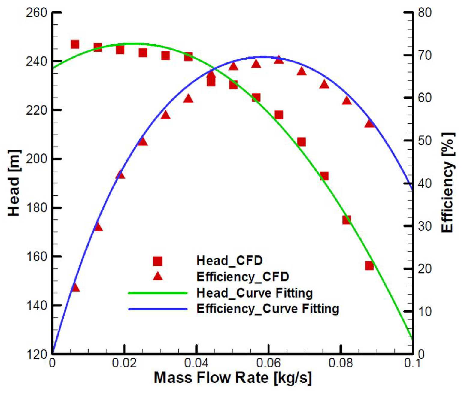
The characteristic curve of the centrifugal pump shows the relationship of the head with the volumetric flow rate and can be used to determine the operating range of the centrifugal pump. Therefore, CFD simulations were performed to investigate the head and efficiency in the case in which the volumetric flow rate was 0.1–1.4 times the design volumetric flow rate to understand the pump performance at each volumetric flow rate. As can see in Figure 11, it is validated that the designed centrifugal pump is similar to the general centrifugal pump characteristic curve. The efficiency of the designed centrifugal pump was 67.27% at the design point. In general, the efficiency of the centrifugal pump is known to be from 40 to 88%, but micro centrifugal pumps may be less than this range [3]. However, it was confirmed that the efficiency of the centrifugal pump using the proposed design method was within the range, even though the size was ultra−small.
Furthermore, the conformance of the designed centrifugal pump with the affinity law was evaluated to validate the design. For geometrically similar pumps, the affinity law can be expressed in Equations (25)–(27), based on the pump head, power, rotational speed, and diameter. In this study, the validity of the affinity law with the change in the rotational speed for a same diameter was examined. The rotational speed was changed from the designed rotational speed of 50,000 rpm to 40,000 rpm and 60,000 rpm. The volumetric flow rate corresponding to each rotational speed was calculated using Equation (25) and set as the outlet boundary condition. Equations (26) and (27), which indicated the relationship between the head and power at each rotational speed and flow rate, were established and validated.
Table 3 lists the theoretically calculated value of the affinity law and the value derived from the CFD simulations at 40,000 rpm and 60,000 rpm. The maximum error was 1.43% and 1.26% at each rotational speed, confirming that the theoretical affinity law was satisfied well. Therefore, the centrifugal pump designed using the proposed method satisfied the design point performance and confirmed to be similar to the characteristic curve of a general centrifugal pump. The designed pump was also consistent with the theoretical affinity law, which further demonstrated the effectiveness of the design technique.
3.3. Performance Comparison with Different Design Methods
In the proposed design method, the impeller was designed based on various empirical formulas, including the Cordier diagram, and the volute was designed using the Stepanoff method. To perform a comparative analysis, the impeller and volute were designed using the Stepanoff method, which has been demonstrated to be appropriate in the general specific speed range, and the pump performance was compared with that of the centrifugal pump designed using the proposed approach at the same Ultra-Low specific speed design point. Notably, the proposed design method was based mostly on empirical equations. However, the blade curvature can be determined using different numbers of arcs in the circular arc method. Therefore, several arc methods were applied and compared to identify the most appropriate circular arc method to design the Ultra-Low specific speed centrifugal pump.
3.3.1. Performance Comparison with the Stepanoff Method for Impeller Design
The Stepanoff method can be used to design centrifugal pumps in the Ultra-Low specific speed range through extrapolation; however, the validity of this application has not been evaluated in the previous studies. Therefore, in this study, the impeller and volute were designed using the Stepanoff method to evaluate the validity of the design method. Because the volute design was the same as in the proposed method, the performance was evaluated considering the impeller design. The design parameters and values are presented in Table 4 and Figure 12. The hydraulic and volumetric efficiency were calculated using the efficiency calculation method described in Section 2.3.1. The same numerical methods were applied in the computational simulation.
When the Stepanoff method is used to the impeller, the head is 206.35 m, and efficiency is 71.08%. The performance values for the pumps designed using the Stepanoff and proposed method are summarized in Table 5. The centrifugal pump head obtained using the Stepanoff method is slightly larger than that at the design point of 205 m but lower than that associated with the proposed method. However, the efficiency is approximately 4% higher than that of the centrifugal pump designed using the proposed approach. The minimum pressure of the impeller, as the suction part, is approximately 53,860 Pa. This value is higher than the vapor pressure of 3170 Pa of water, so there may be no problem operating at the design point. However, this value is lower than that associated with the proposed centrifugal pump design. In other words, in the pump designed by using the Stepanoff method, cavitation can easily occur when the pressure or volumetric flow rate of the tank connected to the centrifugal pump inlet changes from the design condition. Therefore, the impeller design based on the Stepanoff method is disadvantageous. In general, when the suction pressure is high, the pump weight can be decreased by lowering the internal tank pressure. However, because the impeller designed using the Stepanoff method can cause cavitation easily, the tank weight cannot be decreased. Consequently, it is also thought that the centrifugal pump design obtained using the Stepanoff method on a small liquid rocket essential for light weight can be inappropriate.
The low performance of the impeller designed using the Stepanoff method can be seen from the configuration. In general, the head increases with the increase in the diameter of the impeller, exit angle, and exit width. As indicated in Table 4, the centrifugal pump diameter using the Stepanoff method is 24.90 mm, larger than that of the diameter, associated with the proposed pump of 23.96 mm. However, the head of the pump obtained using the Stepanoff method is lower because the outlet angle and width of the centrifugal pump are significantly smaller than those obtained using the proposed design method. The exit angle of the impeller designed using the Stepanoff method is 22.5°.
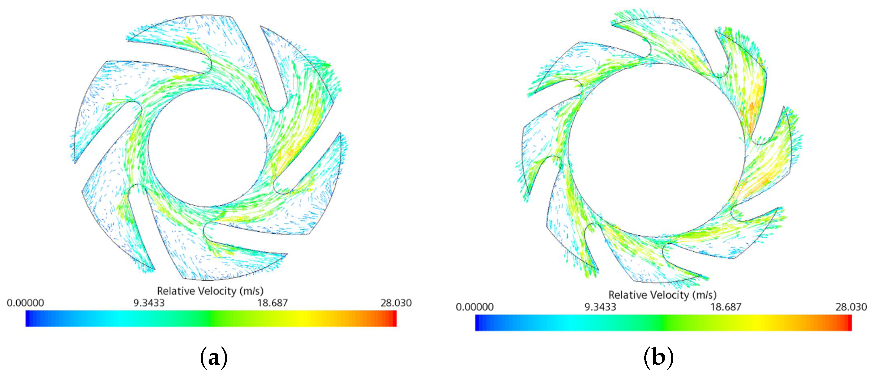
Figure 13 shows the results of computational simulations performed to examine the difference in the performance of the centrifugal pumps obtained using the two design methods. The flow velocity inside the volute of the centrifugal pump obtained using the proposed design method is higher than that associated with the Stepanoff method. As the area of the volute diffuser increases, the velocity decreases and pressure increases, and the internal flow kinetic energy associated with the proposed method is higher than that for the Stepanoff method. Therefore, the energy conversion in the diffuser is larger, leading to a larger head than that pertaining to the Stepanoff centrifugal pump.
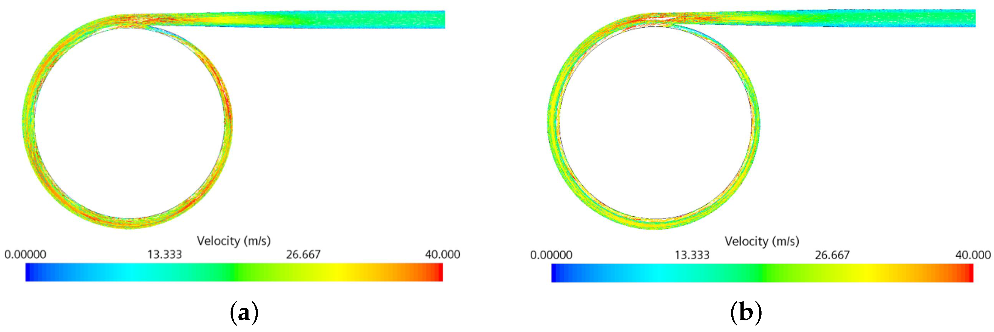
The shape of the blade influences the suction performance at the inlet of the impeller. As indicated in Table 4, the inlet width designed using the Stepanoff method is 0.72 mm, smaller than that determined using the proposed design method. In the Stepanoff method, the number of blades is determined using Equation (28), which is composed only of the exit angle, and thus, the value is higher than that associated with the proposed method. Computational simulations were performed to understand the suction performance, and the results are shown in Figure 14. Specifically, the cross-sectional velocity of the flow at the blade position at the minimum pressure was observed. The velocities associated with the proposed method and the Stepanoff method are 24.68 m/s and 28.03 m/s, respectively. The impeller designed using the Stepanoff method has a narrower passage area between the blades at the inlet side and thus a higher speed and lower pressure than the centrifugal pump designed using the proposed method under the same flow conditions, resulting in low suction performance.
3.3.2. Performance Differences with the Blade Curvature
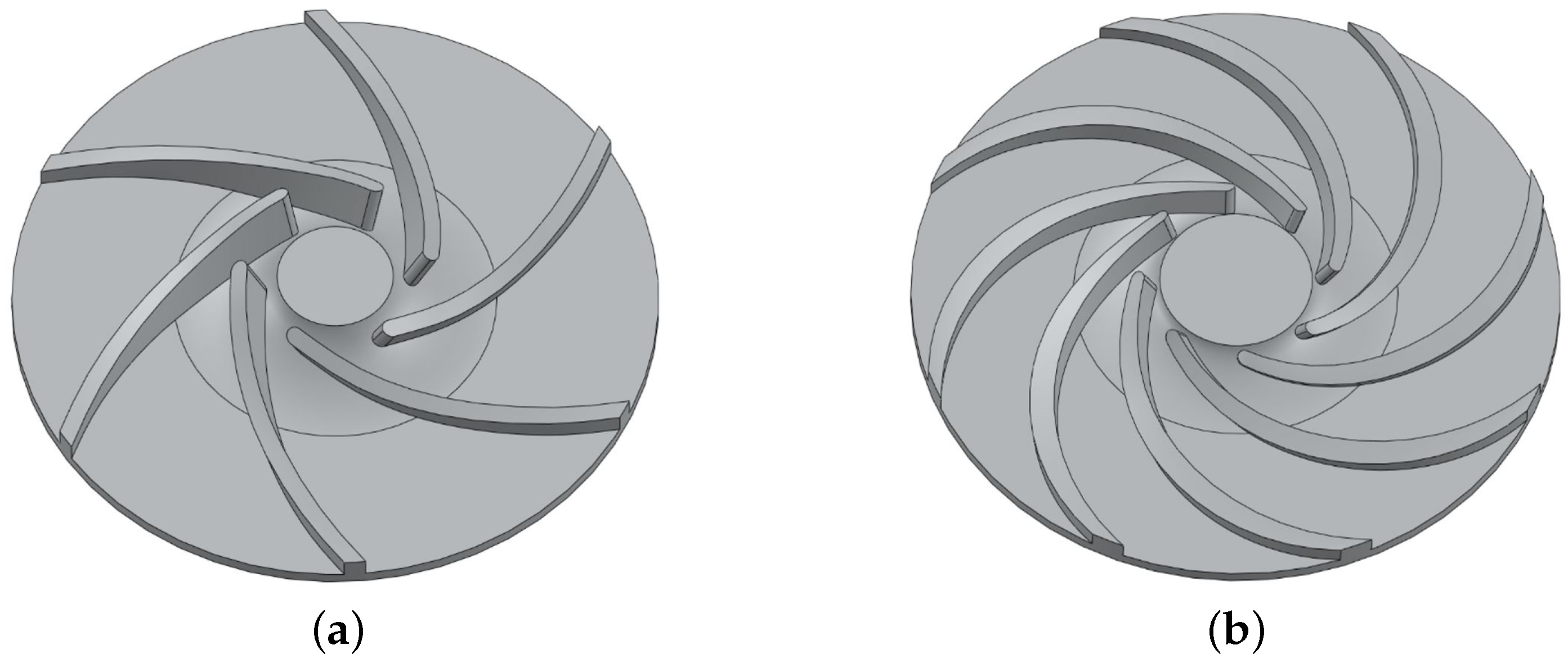
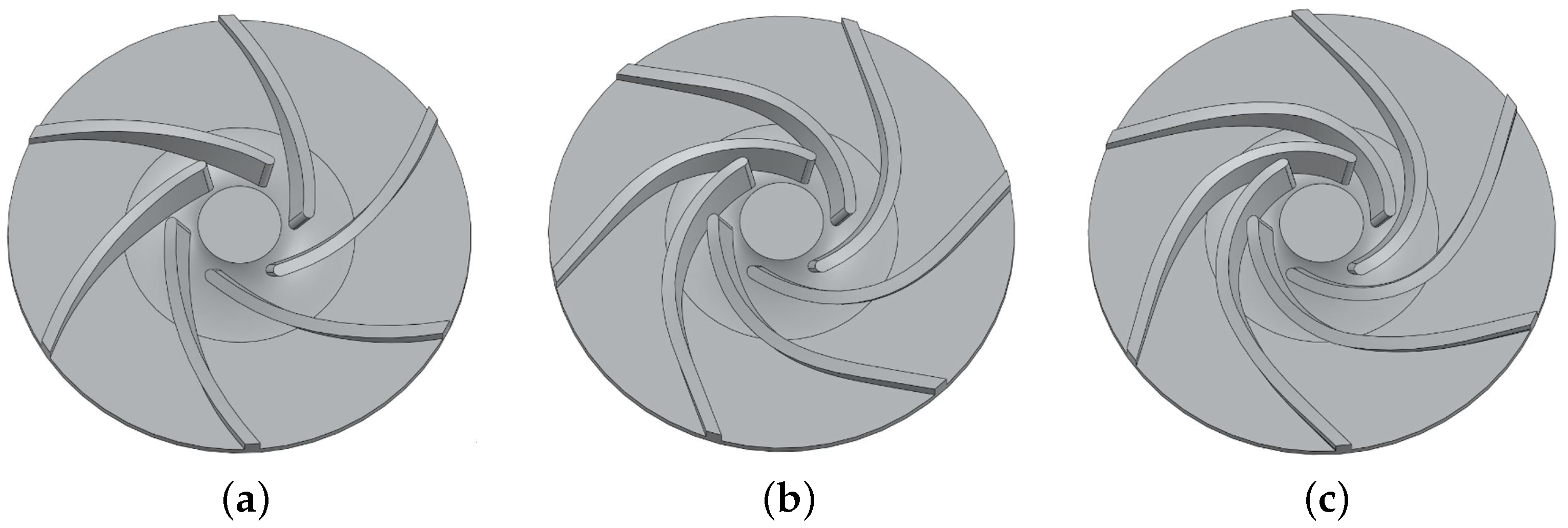
The proposed design method was based on empirical formulas. However, unlike other methods, the circular arc method for designing the blade curvature uses geometric values such as the angle and diameter of the blade inlet and outlet [47]. Therefore, the performance of the pump designed using different circular arc methods was compared through computational simulations to confirm the most appropriate design method. Except for the parameters of the circular arc method, the other variables and simulation parameters were applied the same. The blade curvature was determined by dividing the length between the inlet and outlet diameter by a certain number of arcs. Therefore, the blade curvature was determined in order from the inlet to the outlet. The values are summarized in Table 6, and the resulting shapes are shown in Figure 15.
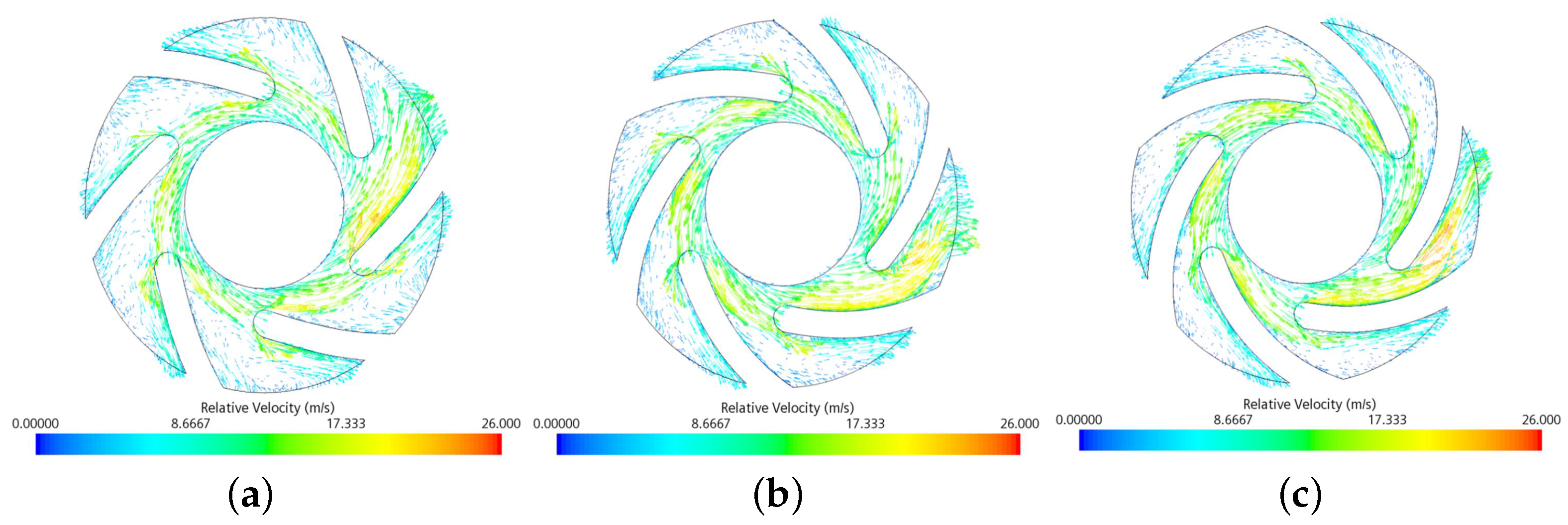
The head values for the single, double, and triple arc method are 217.25 m, 216.78 m, and 215.04 m, respectively, and the efficiencies are 67.27%, 68.21%, and 69.55%. The efficiency increases with the number of arcs. The minimum pressure on the blade for the single, double, and triple arc methods is 114,540 Pa, 164,100 Pa, and 139,370 Pa, respectively, which were similar, and all values are summarized in Table 7. The minimum pressure of the blade has the highest velocity due to the smallest initial area of the impeller, which may result in the lowest pressure. The cross-sectional velocity of the flow at the minimum pressure location on the blade is shown in Figure 16.
The maximum velocity in the cross-sectional area for the single, double, and triple arc method is 25.83 m/s, 24.04 m/s, 24.95 m/s, respectively. The suction performance is the highest in the doubles arc method. For pumps with a high suction performance, the weight can be decreased by lowering the tank pressure. However, the effect is insignificant in the analysis because the minimum pressure difference between the three arc methods is 50,000 Pa or less. Considering that the design goal of this study is the Ultra-Low specific speed micro centrifugal pump for small liquid rocket engines, it is reasonable to apply the single arc method in the design, which has the simplest implementation.
4. Conclusions
Recently, the need for small liquid rocket engines with low thrust has witnessed a considerable increase. Therefore, for the miniaturization and light weight of the engine, a single-stage, low volumetric flow rate, and high head centrifugal pump of the Ultra-Low specific speed is required. In this study, the design method for an Ultra-Low specific speed centrifugal pump for a small liquid rocket engine was developed, and the design feasibility was validated through CFD simulations. The design method was based on various empirical formulas for each design variable. In addition, the design feasibility was validated by evaluating the pressurization performance for an Ultra-Low specific speed centrifugal pump for a small liquid rocket engine with a thrust of several hundred Newtons.
The results demonstrated that the designed pump satisfied the pressurization performance at the design point and was similar to the characteristic curve and theoretical pump affinity law. In addition, the performance of pumps designed using the proposed method and the Stepanoff method, which is commonly used for general specific speed pumps, was compared in the Ultra-Low specific speed range through CFD simulations. The head achieved using the Stepanoff method was lower than that of the proposed method. The minimum pressure at the pump inlet associated with the Stepanoff method was higher than the vapor pressure, and thus, cavitation was not expected to occur. However, the suction performance of the Stepanoff pump was lower than that of the pump designed using the proposed method.
The circular arc method was used to determine the blade curvature for the centrifugal pump, and the appropriate number of arcs for designing an Ultra-Low specific speed centrifugal pump was determined. The number of arcs did not considerably influence the pump performance, and thus, the simplest arc method was considered the most appropriate method for determining the blade curvature, considering the simplicity and productivity. Overall, the proposed method could rapidly determine a pump shape that could satisfy the requirements in the initial design stage. The proposed method can be used to design appropriate Ultra-Low specific speed centrifugal pumps for small liquid rocket engines.
Author Contributions
Conceptualization, H.J.L.; funding acquisition, T.-S.R. and H.H.; investigation, H.I.K.; methodology, H.I.K.; project administration, H.J.L.; supervision, T.-S.R., H.H. and H.J.L.; validation, H.I.K.; writing—original draft, H.I.K.; writing—review and editing, H.J.L. All authors have read and agreed to the published version of the manuscript.
Funding
This research received no external funding.
Data Availability Statement
Data is contained within the article.
Acknowledgments
This research was supported by through the Space Core Technology Development Program of the National Research Foundation (NRF) funded by the Ministry of Science and ICT (MICT) of the Republic of Korea (Grant No. NRF-2021M1A3B8078915).
Conflicts of Interest
The authors declare no conflict of interest.
References
- Karassik, I.J.; Messina, J.P.; Cooper, P.; Heald, C.C. Pump Handbook, 3rd ed.; McGraw-Hill Professional: New York, NY, USA, 2000. [Google Scholar]
- Srinivasan, K.M. Rotodynamic Pumps (Centrifugal and Axial), 1st ed.; New Age International: Delhi, India, 2008. [Google Scholar]
- Gulich, J.F. Centrifugal Pump, 2nd ed.; Springer: New York, NY, USA, 2010. [Google Scholar]
- Lobanoff, V.S.; Ross, R.R. Centrifugal Pumps: Design and Application, 2nd ed.; Gulf Professional Publishing: Houston, TX, USA, 1992. [Google Scholar]
- Stepanoff, A.J. Centrifugal and Axial Flow Pumps, 2nd ed.; John Wiley and Sons: Hoboken, NJ, USA, 1957. [Google Scholar]
- Campbell, W.E.; Farquhar, J. Centrifugal Pumps for Rocket Engines. Available online: https://ntrs.nasa.gov/api/citations/19750003130/downloads/19750003130.pdf (accessed on 11 July 2022).
- Choi, J.; Huh, H.; Ki, W. Technology and Development Trends of Small Launch Vehicles. J. Korean Soc. Propuls. Eng. 2020, 24, 91–102. [Google Scholar] [CrossRef]
- Kopacz, J.R.; Herschitz, R.; Roney, J. Small satellites an overview and assessment. Acta Astronaut. 2020, 170, 93–105. [Google Scholar] [CrossRef]
- Sandau, R. Status and trends of small satellite missions for Earth observation. Acta Astronaut. 2010, 66, 1–12. [Google Scholar] [CrossRef]
- Ayad, A.F.; Abdalla, H.M.; Aly, A.A.E. Effect of semi-open impeller side clearance on the centrifugal pump performance using CFD. Aerosp. Sci. Technol. 2015, 47, 247–255. [Google Scholar] [CrossRef]
- Gamal, R.H.; Elyamin, A.; Bassily, M.A.; Khalil, K.Y.; Gomaa, M.S. Effect of impeller blades number on the performance of a centrifugal pump. Alex. Eng. J. 2019, 58, 39–48. [Google Scholar]
- Luo, X.; Zhang, Y.; Peng, J.; Xu, H.; Yu, W. Impeller inlet geometry effect on performance improvement for centrifugal pumps. J. Mech. Sci. Technol. 2008, 22, 1971–1976. [Google Scholar] [CrossRef]
- Tan, L.; Zhu, B.; Cao, S.; Bing, H.; Wang, Y. Influence of blade wrap angle on centrifugal pump performance by numerical and experimental study. Chin. J. Mech. Eng. 2014, 27, 171–177. [Google Scholar] [CrossRef]
- Alemi, H.; Nourbakhsh, S.A.; Raisee, M.; Najafi, A.F. Effects of Volute Curvature on Performance of a Low Specific-Speed Centrifugal Pump at Design and Off-Design Conditions. J. Turbomach. 2015, 137, 041009. [Google Scholar] [CrossRef]
- Alemi, H.; Nourbakhsh, S.A.; Raisee, M.; Najafi, A.F. Effect of the volute tongue profile on the performance of a low specific speed centrifugal pump. Proc. Inst. Mech. Eng. Part A J. Power Energy 2014, 229, 210–220. [Google Scholar] [CrossRef]
- Lee, S.H.; Lee, D.R. Flow Analysis of The Impeller with Different Inlet Angle in the Centrifugal Pump. J. Comput. Fluids Eng. 2016, 21, 58–63. [Google Scholar] [CrossRef]
- Jin, H.B.; Kim, M.J.; Son, C.H.; Chung, W.J. Spiral Casing of a Volute Centrifugal Pump Effects of the Cross Sectional Shape. KSFM J. Fluid Mach. 2013, 16, 28–34. [Google Scholar] [CrossRef]
- Lee, J.H.; Hur, N.; Yoon, I.S. Numerical Study of a Centrifugal Pump Performance with Various Volute Shape. J. Comput. Fluids Eng. 2015, 20, 35–40. [Google Scholar] [CrossRef]
- Zhou, L.; Shi, W.; Wu, S. Performance Optimization in a Centrifugal Pump Impeller by Orthogonal Experiment and Numerical Simulation. Adv. Mech. Eng. 2013, 5, 385809. [Google Scholar] [CrossRef]
- Han, X.; Kang, Y.; Li, D.; Zhao, W. Impeller Optimized Design of the Centrifugal Pump: A Numerical and Experimental Investigation. Energies 2018, 11, 1444. [Google Scholar] [CrossRef]
- Pei, J.; Wang, W.; Yuan, S.; Zhang, J. Optimization on the Impeller of a Low-specific-speed Centrifugal Pump for Hydraulic Performance Improvement. Chin. J. Mech. Eng. 2016, 29, 992–1002. [Google Scholar] [CrossRef]
- Zhao, A.; Lai, Z.; Wu, P.; Cao, L.; Wu, D. Multi—objective optimization of a low specific speed centrifugal pump using an evolutionary algorithm. Eng. Optim. 2016, 48, 1251–1274. [Google Scholar]
- Kim, S.; Choi, Y.S.; Yoon, J.Y.; Kim, D.S. Design Optimization of Centrifugal Pump Impeller Using DOE. KSFM J. Fluid Mach. 2018, 11, 36–42. [Google Scholar]
- Yun, J.E. Development of a Centrifugal Pump Impeller Using Optimal Design Technique. Trans. Korean Soc. Mech. Eng. B 2018, 50, 567–572. [Google Scholar] [CrossRef]
- Pak, E.T.; Yoo, H.S.; Kwon, Y.K. The Development of Software for Design of Centrifugal Pumps. Sol. Energy 1991, 11, 50–60. [Google Scholar]
- Im, H.N.; Kim, J.Y.; Yang, C.J.; Lee, Y.H. Design and Analysis of Centrifugal Pump using Experimental Factor. In Proceedings of the KSME Conference, Seoul, Korea, 2–4 November 2000; pp. 434–440. [Google Scholar]
- Liu, J.; Zhao, X.; Xiao, M. Study on the Design Method of Impeller on Low Specific Speed Centrifugal Pump. Open Mech. Eng. J. 2015, 9, 594–600. [Google Scholar] [CrossRef]
- Choung, Y.D.; Lee, K.B. Performance Evaluation on Impeller Related Parameters Change in Centrifugal Pump of very Low Specific Speed. KSFM J. Fluid Mach. 2011, 14, 11–17. [Google Scholar]
- Choi, Y.D.; Kagawa, S.; Kurokawa, J. Influence of Circular Casing on the Performance of Very Low Specific Speed Centrifugal Pump. KSFM J. Fluid Mach. 2016, 9, 32–39. [Google Scholar]
- Grunde, O.; Morten, O.; Finstad, P.H.E. Very Low Specific Speed Centrifugal Pump— Hydraulic Design and Physical Limitations. J. Fluids Eng. 2018, 140, 071403. [Google Scholar]
- Wang, C.; Zhang, Y.; Hou, H.; Yuan, Z. Theory and application of two-dimension viscous hydraulic design of the Ultra-Low specific-speed centrifugal pump. Proc. Inst. Mech. Eng. Part A J. Power Energy 2019, 234, 58–71. [Google Scholar]
- Hou, H.; Zhang, Y.; Zhou, X.; Zuo, Z.; Chen, H. Optimal hydraulic design of an Ultra-Low specific speed centrifugal pump based on the local entropy production theory. Proc. Inst. Mech. Eng. Part A J. Power Energy 2019, 233, 715–726. [Google Scholar]
- Sieder, J.; Kleebusch, K.; Bach, C.; Tajmar, M. Development History and Verification of the Flight Model of a 500 N Ethanol/LOX Rocket Engine. In Proceedings of the 7th European Conference for Aeronautics and Space Sciences, Milan, Italy, 3–6 July 2017. [Google Scholar]
- Pawel, S.; Kamil, S.; Bartosz, B.; Grzegorz, R.; Adam, O.; Tobiasz, M.; Piotr, W.; Ferran, V.B. Development Status of 500 N-class HTP/TMPDA Bi-propellant Rocket Engine. In Proceedings of the 69th International Astronautical Congress, Bremen, Germany, 1–5 October 2018. [Google Scholar]
- Kim, Y.J.; Kim, M.C.; Kim, J.S. Configuration Design, Hot-firing Test and Performance Evaluation of 200 N-Class GCH4/LOx Small Rocket Engine (Part I: A Preliminary Design and Test Apparatus). J. Korean Soc. Propuls. Eng. 2020, 24, 1–8. [Google Scholar] [CrossRef]
- Kozlov, A.A.; Vorobiev, A.G.; Borovik, I.N.; Kazennov, I.S.; Lahin, A.V.; Bogachev, E.A.; Timofeev, A.N. Development Liquid Rocket Engine of Small Thrust with Combustion Chamber from Carbon—Ceramic Composite Material. In Nanocomposites with Unique Properties and Applications in Medicine and Industry; IntechOpen: London, UK, 2011. [Google Scholar]
- Takita, K.; Nonaka, Y.; Mishima, H.; Hisatsune, K.; Uesugi, K.T.; Sato, E.; Sawai, S. Development of Ceramic Thruster for Spacecraft Propulsion System. In Proceedings of the 4th International Spacecraft Propulsion Conference, Cagliari, Italy, 2–9 June 2004. [Google Scholar]
- Tetsuya, M.; Katasushige, M.; Rtohei, I.; Yoshinori, N. Development of 500N Ceramic Thruster for the PLANET-C Venus Explorer. Mitsubishi Heavy Ind. Ltd. Tech. Rev. 2008, 45, 32–35. [Google Scholar]
- Kwak, H.D.; Kim, D.J.; Kim, J.S.; Kim, J.; Noh, J.G.; Park, P.G.; Bae, J.H.; Shin, J.H.; Yoon, S.H.; Lee, H.; et al. Performance Test of a 7 tonf Liquid Rocket Engine Turbopump. J. Korean Soc. Propuls. Eng. 2015, 19, 65–72. [Google Scholar]
- Welle, R.P.; Murdock, J.W.; Hardy, B.S. A Water Test Facility for Liquid Rocket Engine Turbopump Cavitation Testing. In Proceedings of the 7th International Symposium on Cavitation, Ann Arbor, MI, USA, 16–20 August 2009. [Google Scholar]
- Pauw, J.D.; Veggi, L.; Wagner, B.; Mondal, J.; Klotz, M.; Haidn, O.J. Design Procedure of a Turbopump Test Bench. In Proceedings of the International Symposium on Transport Phenomena and Dynamics of Rotating Machinery, Maui, HI, USA, 16–21 December 2017. [Google Scholar]
- Cordier, O. Ähnlichkeitsbedingungen für Strömungsmaschinen. BWK Bd 1953, 5, 337–340. [Google Scholar]
- Pfleiderer, C. Die Kreiselpumpen für Flüssigkeiten und Gase, 1st ed.; Springer: Berlin, Germany, 1961. [Google Scholar]
- Wiesner, F.J. A Review of Slip Factors for Centrifugal Impellers. J. Eng. Power 1967, 89, 558–572. [Google Scholar]
- Dixon, S.L.; Hall, C.A. Fluid Mechanics and Thermodynamics of Turbomachinery, 7th ed.; Butterworth-Heinemann: Oxford, UK, 2013. [Google Scholar]
- Furst, R.B. Liquid Rocket Engine Centrifugal Flow Turbopumps; NASA-SP-8109; National Aeronautics and Sapce Administration, [for sale by the National Technical Information Service, Springfield, Va.]: Washington, DC, USA, 1973.
- Tuzson, J. Centrifugal Pump Design, 1st ed.; Wiley-Interscience: Hoboken, NJ, USA, 2000. [Google Scholar]
- Round, G.F. Incompressible Flow Turbomachines Design, Selection, Applications, and Theory, 1st ed.; Butterworth-Heinemann: Oxford, UK, 2004. [Google Scholar]
- Wong, Y.W.; Chan, W.K.; Hu, W. Effects of Tongue Position and Base Circle Diameter on the Performance of a Centrifugal Blood Pump. Artif. Organs 2007, 31, 639–645. [Google Scholar] [PubMed]
- Ayad, A.F.; Abdalla, H.M.; El-Azm, A.A. Study of the Effect of Impeller Side Clearance on the Centrifugal Pump Performance Using CFD. In Proceedings of the ASME 2015 International Mechanical Engineering Congress and Exposition, Houston, TX, USA, 13–19 November 2015. [Google Scholar]
- Pyun, K.B.; Kim, J.H.; Choi, Y.S.; Yoon, J.Y. Design Optimization of a Centrifugal Pump Impeller using RSM and Design of Volute. KSFM J. Fluid Mach. 2012, 15, 39–45. [Google Scholar]
- Shim, H.S.; Kim, K.Y.; Choi, Y.S. Internal Flow Characteristics of a Centrifugal Pump with Various Specific Speeds. KSFM J. Fluid Mach. 2017, 20, 26–35. [Google Scholar]
Figure 1.
Optimal geometry as a function of best efficiency point(BEP) and specific speed [1].
Figure 1.
Optimal geometry as a function of best efficiency point(BEP) and specific speed [1].

Figure 2.
Process of Ultra-Low specific speed centrifugal pump design.

Figure 3.
Cordier diagram [45].
Figure 3.
Cordier diagram [45].

Figure 4.
Single arc method for blade design [48].
Figure 4.
Single arc method for blade design [48].

Figure 5.
Volute cutaway.

Figure 6.
Design constants of volute by Stepanoff [5].
Figure 6.
Design constants of volute by Stepanoff [5].

Figure 7.
Ultra-Low specific speed centrifugal pump configuration: (a) impeller; (b) blade; (c) volute.
Figure 7.
Ultra-Low specific speed centrifugal pump configuration: (a) impeller; (b) blade; (c) volute.

Figure 8.
CFD domain.

Figure 9.
Grid configuration: (a) grid of the domain; (b) grid of the impeller.

Figure 10.
Impeller pressure scene.

Figure 11.
Pump characteristic curve.

Figure 12.
Impeller configuration: (a) proposed design method; (b) Stepanoff method.

Figure 13.
Volute velocity field: (a) proposed method; (b) Stepanoff method.

Figure 14.
Volute field over the impeller: (a) proposed method; (b) Stepanoff method.

Figure 15.
Impeller configurations based on different design methods: (a) single arc method; (b) double arc method; (c) triple arc method.
Figure 15.
Impeller configurations based on different design methods: (a) single arc method; (b) double arc method; (c) triple arc method.

Figure 16.
Velocity field for various impellers: (a) single arc method; (b) double arc method; (c) triple arc method.
Figure 16.
Velocity field for various impellers: (a) single arc method; (b) double arc method; (c) triple arc method.


Table 1.
Design parameters of the centrifugal pump.
| Geometric Parameter | Value |
|---|---|
| Impeller inlet diameter, (mm) | 6.25 |
| Impeller outlet diameter, (mm) | 23.96 |
| Impeller outlet angle, (°) | 51.7 |
| Impeller inlet width, (mm) | 1.56 |
| Impeller outlet width, (mm) | 0.31 |
| Number of blades, z | 6 |
| Volute base circle diameter, (mm) | 24.82 |
| Volute width, (mm) | 0.49 |
Table 2.
Grid dependency results.
| Number of cells | 365,622 | 601,660 | 1,331,650 | 2,717,280 | 3,314,246 |
| Cell size | 0.3 mm | 0.22 mm | 0.14 mm | 0.1 mm | 0.09 mm |
| Head | 204.93 m | 212.33 m | 216.42 m | 217.25 m | 217.44 m |
Table 3.
Conformance with affinity law at 40,000 and 60,000 rpm.
| 40,000 rpm (0.0502 kg/s) | 60,000 rpm (0.0754 kg/s) | |||
|---|---|---|---|---|
| Head | Power | Head | Power | |
| Theoretical | 139.04 m | 68.46 W | 312.84 m | 231.04 W |
| Numerical | 137.17 m | 67.48 W | 316.59 m | 233.94 W |
| Error | 1.34% | 1.43% | 1.20% | 1.26% |
Table 4.
Design parameters of the pump using the proposed method and Stepanoff method.
| Geometric Parameters | Proposed Design | Stepanoff |
|---|---|---|
| Impeller inlet diameter, (mm) | 6.25 | 6.58 |
| Impeller outlet diameter, (mm) | 23.96 | 24.90 |
| Impeller outlet angle, (°) | 51.7 | 22.5 |
| Impeller inlet width, (mm) | 1.56 | 0.72 |
| Impeller outlet width, (mm) | 0.31 | 0.20 |
| Number of blades, z | 6 | 8 |
| Volute base circle diameter, (mm) | 24.82 | 25.80 |
| Volute width, (mm) | 0.49 | 0.32 |
Table 5.
Performance of pumps obtained using different design methods.
| Proposed Design Method | Stepanoff Method | |
|---|---|---|
| Head | 217.25 m | 206.35 m |
| Efficiency | 67.27% | 71.08% |
| Min Pressure | 114,540 Pa | 53,860 Pa |
Table 6.
Results of various impeller designs.
| Curvature | Single Arc Method | Double Arc Method | Triple Arc Method |
|---|---|---|---|
| Arc 1 | 15.45 mm | 6.83 mm | 5.39 mm |
| Arc 2 | − | 49.75 mm | 14.05 mm |
| Arc 3 | − | − | 139.56 mm |
Table 7.
Performance of various impellers.
| Single Arc Method | Double Arc Method | Triple Arc Method | |
|---|---|---|---|
| Head | 217.25 m | 216.78 m | 215.04 m |
| Efficiency | 67.27% | 68.21% | 69.55% |
| Min Pressure | 114,540 Pa | 164,100 Pa | 139,370 Pa |
Publisher’s Note: MDPI stays neutral with regard to jurisdictional claims in published maps and institutional affiliations. |
© 2022 by the authors. Licensee MDPI, Basel, Switzerland. This article is an open access article distributed under the terms and conditions of the Creative Commons Attribution (CC BY) license (https://creativecommons.org/licenses/by/4.0/).
Share and Cite
MDPI and ACS Style
Kim, H.I.; Roh, T.-S.; Huh, H.; Lee, H.J. Development of Ultra-Low Specific Speed Centrifugal Pumps Design Method for Small Liquid Rocket Engines. Aerospace 2022, 9, 477. https://doi.org/10.3390/aerospace9090477
AMA Style
Kim HI, Roh T-S, Huh H, Lee HJ. Development of Ultra-Low Specific Speed Centrifugal Pumps Design Method for Small Liquid Rocket Engines. Aerospace. 2022; 9(9):477. https://doi.org/10.3390/aerospace9090477
Chicago/Turabian StyleKim, Hye In, Tae-Seong Roh, Hwanil Huh, and Hyoung Jin Lee. 2022. "Development of Ultra-Low Specific Speed Centrifugal Pumps Design Method for Small Liquid Rocket Engines" Aerospace 9, no. 9: 477. https://doi.org/10.3390/aerospace9090477
Note that from the first issue of 2016, this journal uses article numbers instead of page numbers. See further details here.