Impeller Optimized Design of the Centrifugal Pump: A Numerical and Experimental Investigation


1
Key Laboratory of Hydraulic Machinery Transients, Ministry of Education, Wuhan University, Wuhan 430072, China
2
Hubei Key Laboratory of Waterjet Theory and New Technology, Wuhan University, Wuhan 430072, China
3
School of Power and Mechanical Engineering, Wuhan University, Wuhan 430072, China
4
Collaborative Innovation Center of Geospatial Technology, Wuhan 430079, China
5
School of Energy and Power Engineering, Lanzhou University of Technology, Lanzhou 730050, China
*
Author to whom correspondence should be addressed.
Energies 2018, 11(6), 1444; https://doi.org/10.3390/en11061444
Submission received: 22 March 2018
/
Revised: 8 May 2018
/
Accepted: 17 May 2018
/
Published: 4 June 2018
(This article belongs to the Special Issue Engineering Fluid Dynamics 2018)
Abstract
:Combined numerical simulation with experiment, blade wrap angle, and blade exit angle are varied to investigate the optimized design of the impeller of centrifugal pump. Blade wrap angles are 122°, 126°, and 130°. Blade exit angles are 24°, 26°, and 28°. Based on numerical simulation, internal flow of the centrifugal pump with five different impellers under 0.6, 0.8, 1.0, 1.2, and 1.5 Qd are simulated. Variations of static pressure, relative velocity, streamline, and turbulent kinetic energy are analyzed. The impeller with blade wrap angle 126° and blade exit angle 24° are optimal. Distribution of static pressure is the most uniform and relative velocity sudden changes do not exist. Streamlines are the smoothest. Distribution scope of turbulent kinetic energy is the smallest. Based on performance experiments, head and efficiency of the centrifugal pump with the best impeller are tested. The values of head and efficiency are higher than that of the original pump. Centrifugal pump with the best impeller has better hydraulic performance than the original centrifugal pump.
1. Introduction
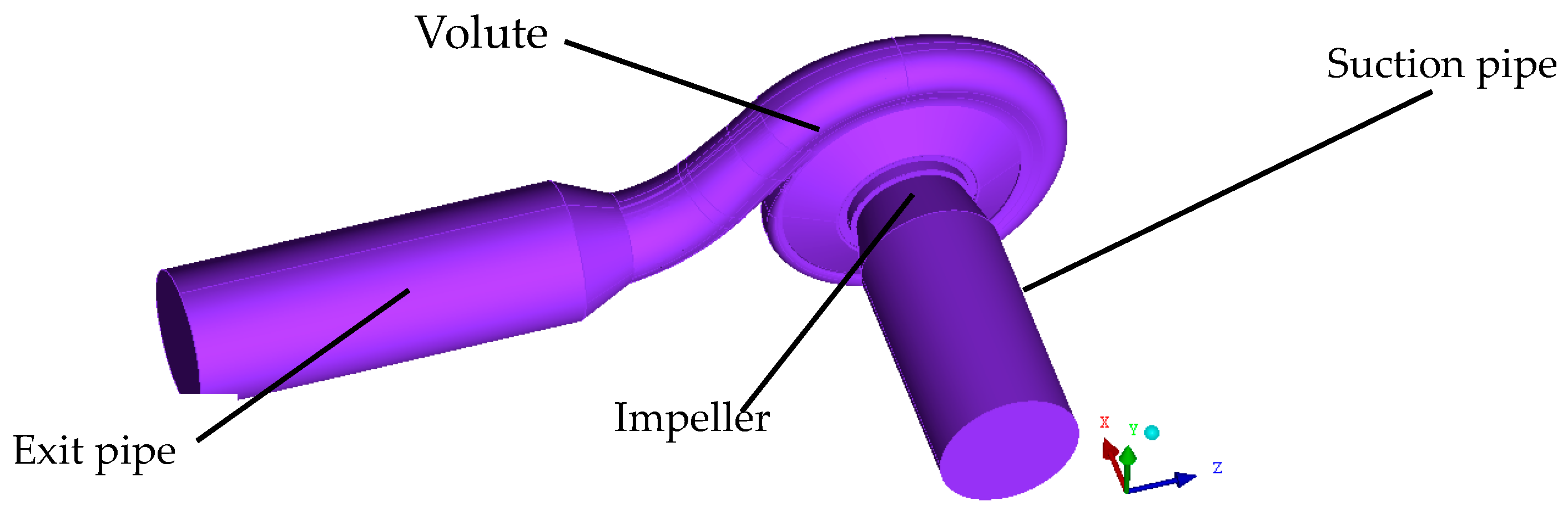
A centrifugal pump is one kind of general machinery [1] which is widely and fully utilized in the industrial and agricultural fields [2], such as irrigation and water supply. It normally includes four different parts: suction pipe, impeller, volute, and exit pipe. The impeller is the core part and it converts the mechanical energy into pressure energy [3], which directly determines the transport capacity and the hydraulic performances of centrifugal pump. So, optimized design of the impeller is essential and significant for the efficient operation of a centrifugal pump [4,5].
One-dimensional flow theory, two-dimensional flow theory, and three-dimensional flow theory are three basic theories to optimally design the centrifugal pump [6,7]. Two-dimensional flow theory regards the distribution of meridian velocity across the cross-section as symmetrical. The flow is one kind of potential flow. Optimized design of hydraulic machinery in engineering fields, which is based on two-dimensional flow theory, is rare. It is only employed to optimally design the higher specific speed impellers of mixed-flow pump and runners of mixed-flow turbine. Three-dimensional flow theory, proposed by Wu [8], is also called S1 and S2 relative flow surface theory. In this method, the three-dimensional flow is converted into two two-dimensional flows in the surfaces S1 and S2. Only in the ideal conditions of flow being inviscid, incompressible, and unsteady, can this method be applied to design the impeller successfully. This method is difficult and complex. Thus, it is not always employed to optimally design an impeller for a centrifugal pump in the engineering field. However, one-dimensional flow theory, which is based on Euler equations, is convenient and simple. Flow in the meridional surface is symmetrical. Engineers coming from home and abroad factories widely employ one-dimensional flow theory to optimally design an impeller for a centrifugal pump [9,10,11].
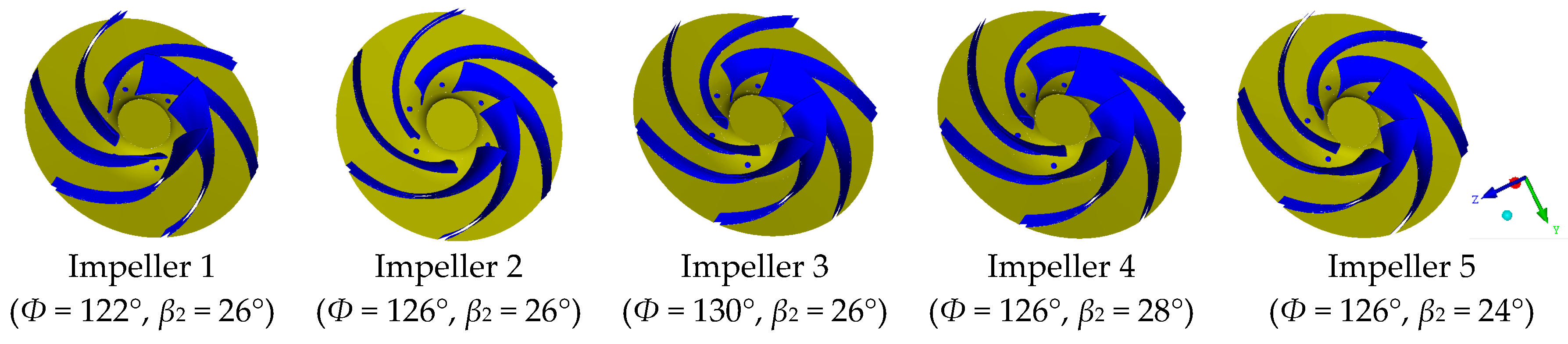
Blade exit angle (Ф) and blade wrap angle (β2) are two significant parameters in the impeller optimized design process according to one-dimensional flow theory [12,13,14,15]. The hydraulic performance of a centrifugal pump is mainly determined by these parameters. In the actual optimized design process, blade exit angle often varies from 15° to 40° and blade wrap angle often varies from 90° to 130° [16]. Some scholars studied the effects of blade exit angle and blade wrap angle on the hydraulic performances of the centrifugal pump [17,18,19]. The selection of blade wrap angle and blade exit angle mainly depend on the specific speed of the centrifugal pump and the actual optimized design experience. If the blade wrap angle is too large, the impeller friction area becomes large, which is bad for the improvement of efficiency. If the blade wrap angle is too small, the impeller cannot control the flow of water effectively and the impeller cannot operate stably. For the blade exit angle, a moderate value could effectively improve the hydraulic performances of the centrifugal pump. Comprehensively considering the specific speed of the target centrifugal pump (ns = 112) and the effects of blade wrap angle and blade exit angle on the hydraulic performances of the centrifugal pump, the variation scope of the blade wrap angle and blade exit angle was selected carefully. The blade wrap angle was tested in the range of 120° to 130° and the values were Ф = 122°, 126°, and 130°, respectively. The blade exit angle was tested in the range of 20° to 30° and the values were β2 = 24°, 26°, and 28°, separately.
2. Basic Parameters of the Impeller
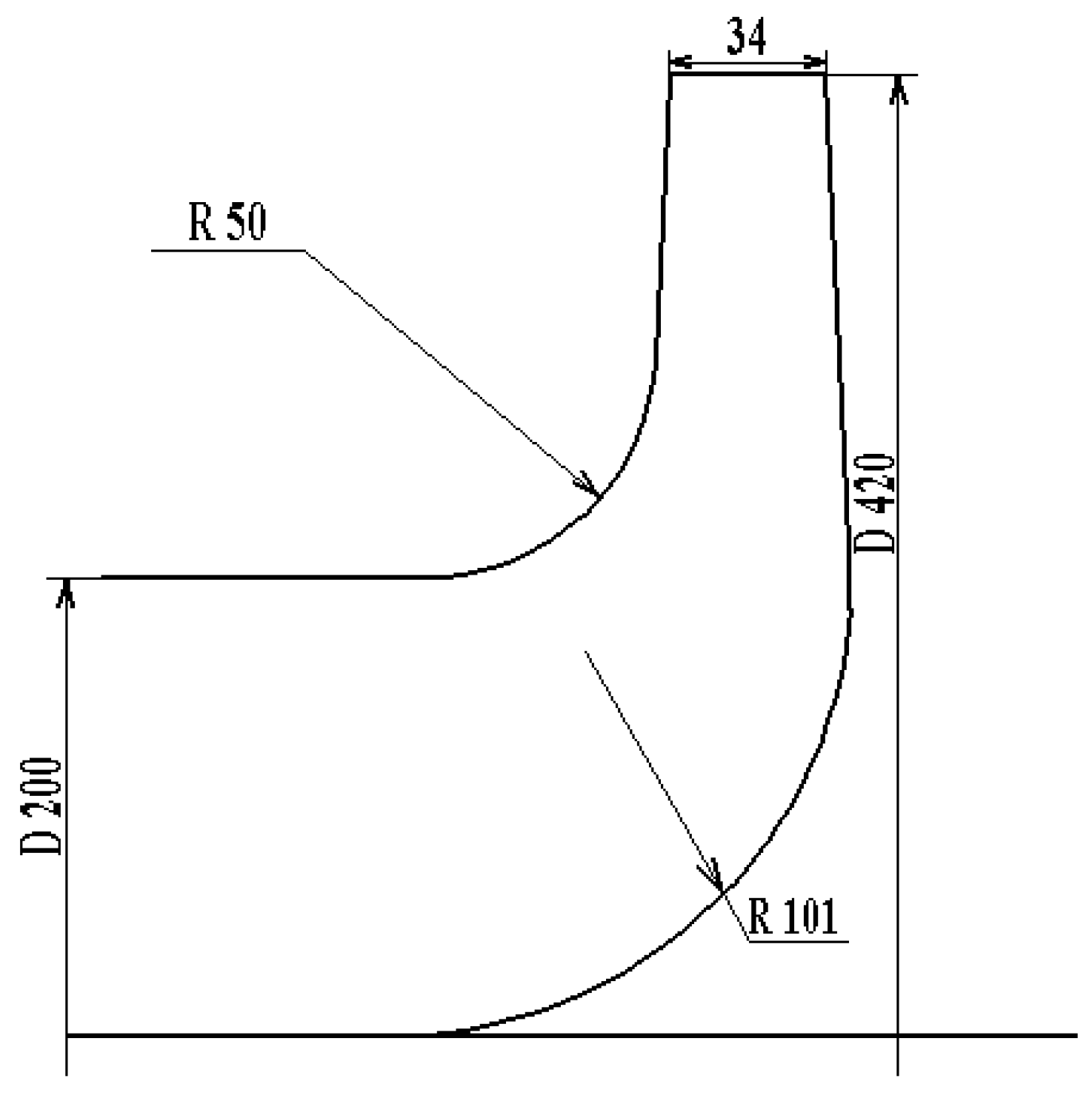
The inlet diameter of the impeller D1 = 200 mm and the outlet diameter D2 = 420 mm. The exit width b2 = 34 mm. The original blade wrap angle Φ = 120°. The original blade exit angle β2 = 26°. The basic parameters of the impeller are shown in Figure 1.
3. Method to Modify the Impeller
The impeller shape is directly determined by the blade profiles. In the impeller optimization design process, all blade profiles must be smooth. The bend of the blade profiles should be in one single direction. An ‘S’ shape should not exist [16,20,21]. All blade profiles should be symmetrical. The blade profile differential equation is
Here, s is the axial streamline. θ denotes the axial angle. r represents the radius of one arbitrary point in the blade profile. β is the blade angle.
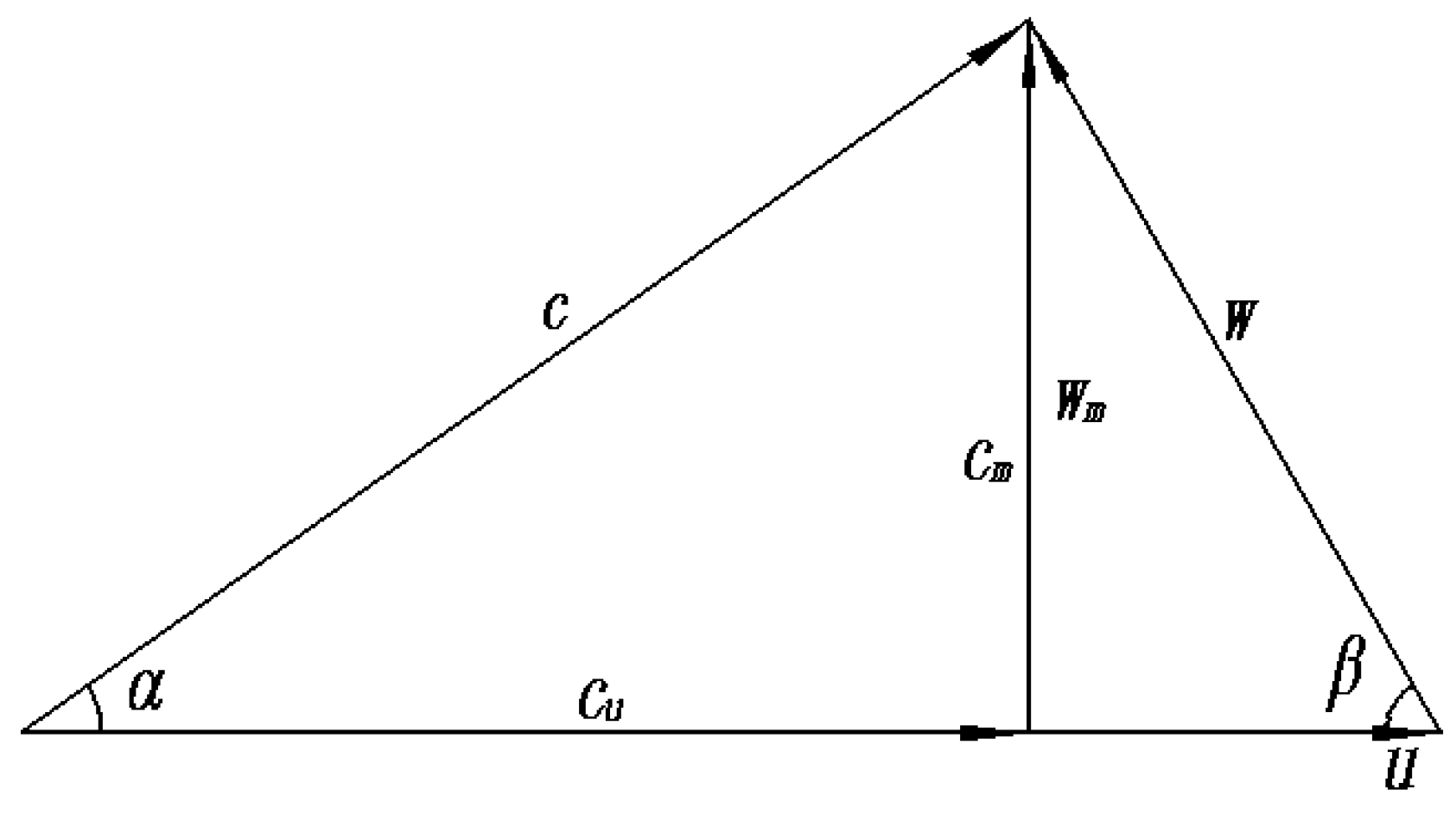
The speed triangle is shown in Figure 2. Here, c represents absolute velocity, w is the relative velocity, and u is the following velocity. cm and wm are the component of absolute velocity and relative velocity in the meridional plane, respectively. cu is the component in the circumferential plane.
Based on the speed triangle, tanβ could be described as
Thus,
So,
According to the above equations, blade profile optimized design has a closed relation with blade inlet angle (β1), blade exit angle (β2), and blade wrap angle (Φ). Three different methods are usually employed to modify the blade profiles. They are that
- (1)
- β1 is the constant. β2 and Φ are changed.
- (2)
- β1 and β2 are fixed. Φ is varied.
- (3)
- β2 and Φ are invariant. β1 is altered.
Method 1 (β1 is the constant. β2 and Φ are changed.) was always employed to optimally design the impeller. As shown in Table 1, the blade exit angle of Schemes 1–3 was identical and the blade wrap angles varied from 122° to 130°, which were employed to investigate the effects of different blade wrap angles on the optimized design of the centrifugal pump. For Schemes 2, 4, and 5, the blade wrap angle was the same and the blade exit angle was changed, which was used to discuss the effects of diverse blade exit angles on the optimized design of the centrifugal pump.
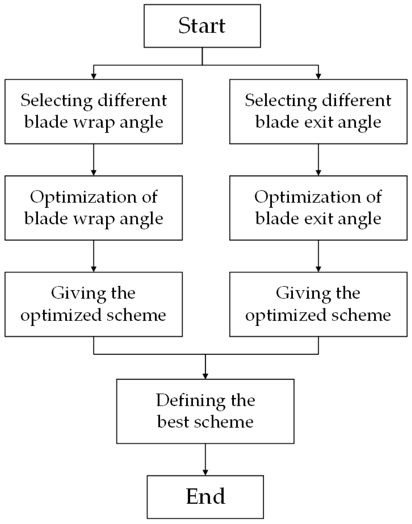
The impeller optimized design procedure is that, via the analysis of effects of blade wrap angle (Schemes 1–3) on the hydraulic performances of the centrifugal pump, one optimal scheme could be determined via computational fluid dynamics (CFD). According to the discussion of effects of blade exit angle (Schemes 2, 4, and 5) on the variations of head and efficiency, one optimal scheme could be got by numerical simulation. Then, these two different schemes are compared and the best one could be obtained. The optimized procedure includes two main parts, as shown in Figure 3.
The physical models of the blades under different blade wrap angle and blade exit angle conditions are given in Figure 4.
4. Numerical Method
4.1. Fundamental Equations
The fundamental equations [22] are employed to describe the flow characteristics in the centrifugal pump, which include two main parts: continuity equation and motion equation, corresponding with mass conservation law and momentum conservation law.
Here, ρ is the density of water. t represents the time. u denotes the velocity. x is the Cartesian coordinate. fi is the body force vector. p is the pressure. μ is the dynamic viscosity.
4.2. Turbulent Model
RNG k-ε turbulent model proposed by Yakhot and Orzag [23] was employed to deal with turbulent flow. In the centrifugal pump, the impeller is the rotating part whose rotation effects could be fully dealt by the turbulent dissipation rate (ε) equation in this turbulent model. On the other hand, the RNG k-ε turbulent model has high-precision, which could guarantee the accuracy of the numerical results.
Here, k is the turbulent kinetic energy. ε is the turbulent dissipation rate. μt is the turbulent viscosity. The five terms, C1ε, C2ε, αk, αε, and cμ are empirical coefficients and the values are 1.42, 1.68, 1.39, 1.39, and 0.09, separately. Gk is one generation term of turbulent kinetic energy which is caused by the mean velocity gradient.
5. Numerical Simulation Setup
5.1. Physical Model
Three-dimensional (3D) single-stage and single-suction centrifugal pump was employed, as shown in Figure 5. The suction pipe was employed to keep the uniform of the flow. Exit pipe was utilized to avoid the backflow. The performance parameters were designed flow rate Qd = 550 m3/h; designed head Hd = 50 m; rated motor power P = 110 KW; and rated rotational speed n = 1480 rpm. The geometric parameters of the impeller and the volute were shown in Table 2.
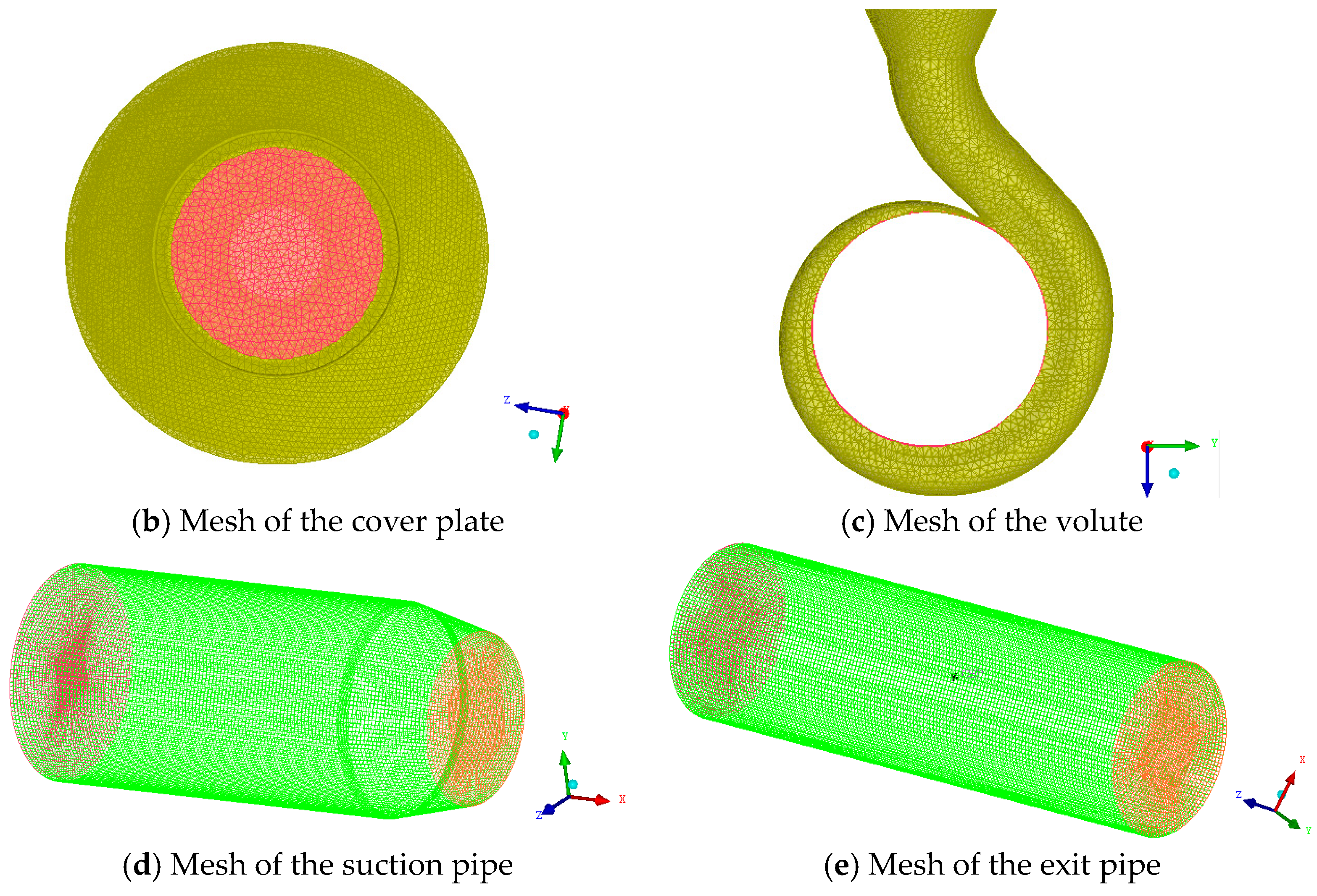
5.2. Mesh Generation
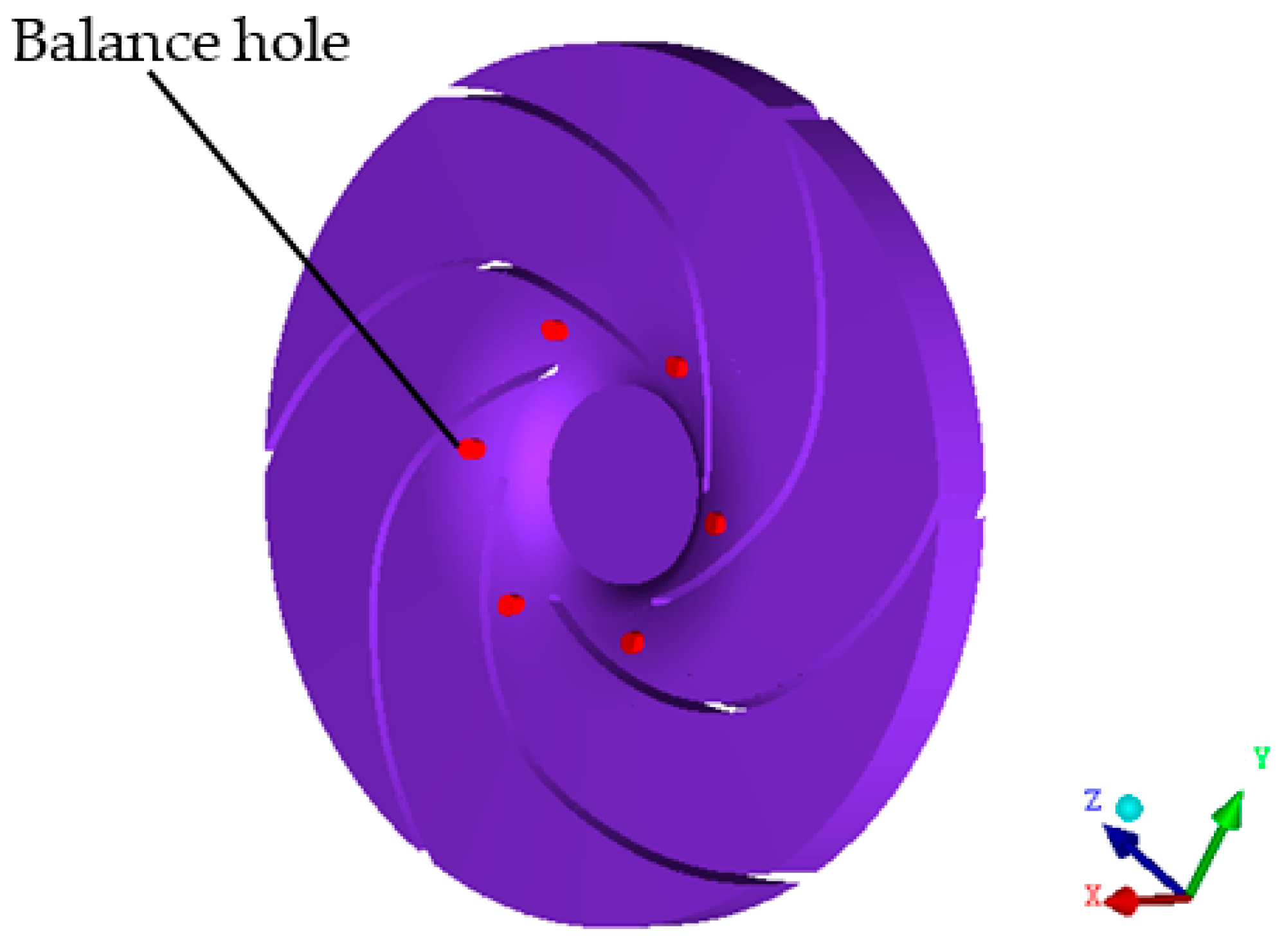
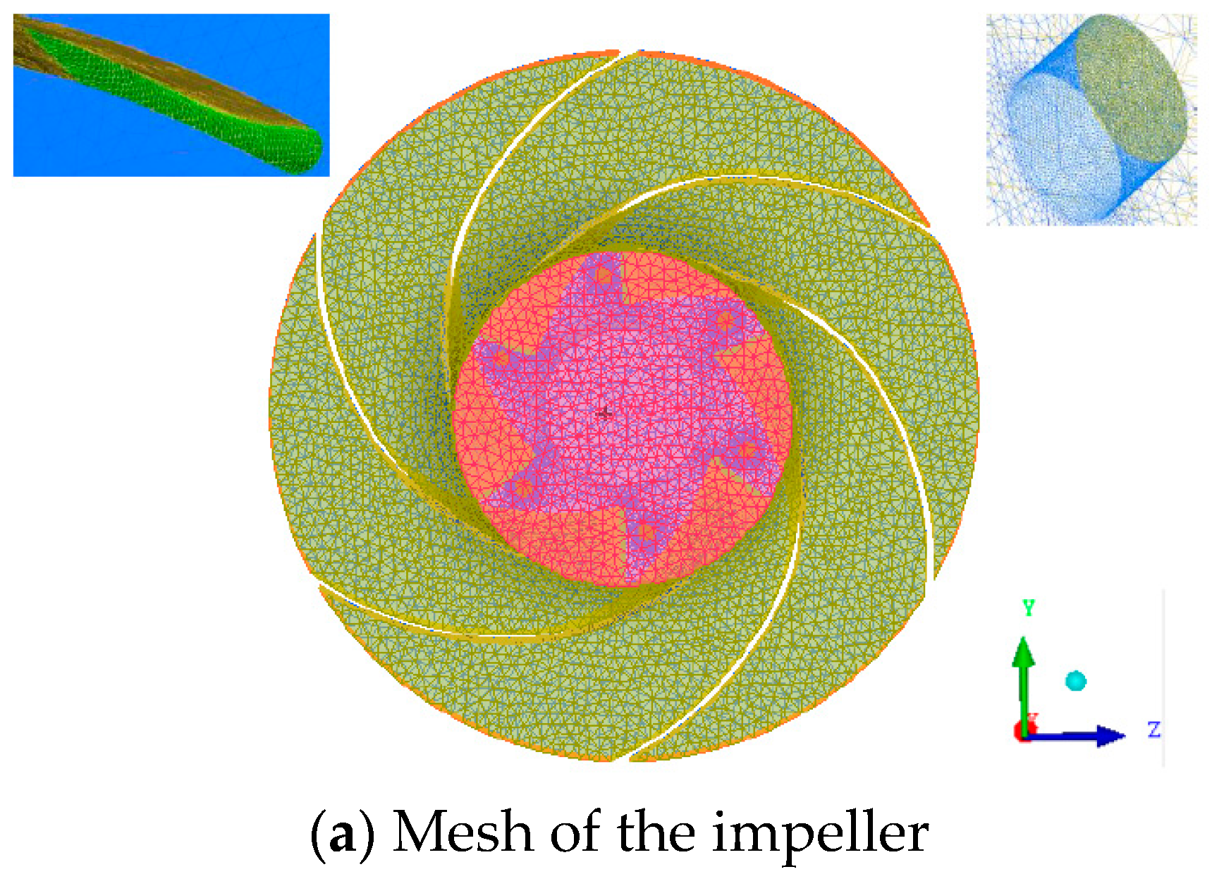
ANSYS-ICEM (15.0, ANSYS, Inc., Canonsburg, PA, USA) is employed to discrete the centrifugal pump computational domains. To guarantee the uniformity of the flow, structured meshes were employed to discretize the computational domains of the suction pipe and exit pipe, as displayed in Figure 8d–e. Fully considering the complex structure of the impeller and the volute, to get the better adaptability of the flow, unstructured meshes were employed to discrete the computational domains of impeller, front and back chamber, and volute, as shown in Figure 8a–c. Meshes in the leading edges of the impeller and balance hole were refined.
Mesh numbers of the five different impellers were 3,472,923, 3,473,052, 3,471,896, 3,472,816, and 3,473,011, respectively. All mesh quality was higher than 0.3. Mesh number and quality of front and back chamber, volute, suction pipe, and exit pipe were displayed in Table 3.
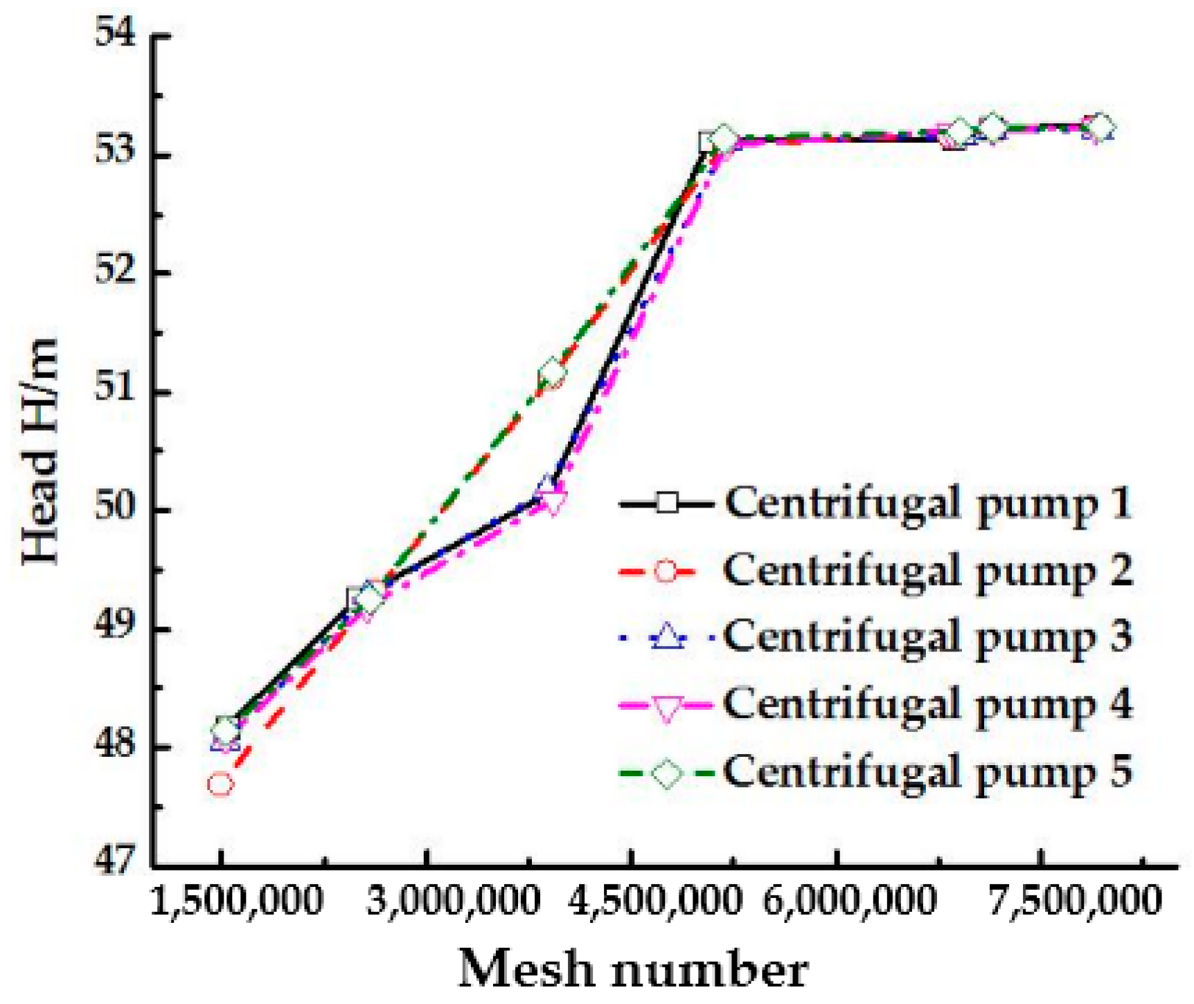
Head under designed flow rate condition was calculated to verify mesh independence. Results indicated that with the increase of mesh number, head increased firstly. Then, the differences of head were slight, as shown in Figure 9. Total mesh numbers of the five different centrifugal pumps were 7,139,826, 7,146,497, 7,143,016, 7,145,682, and 7,147,024, separately.
5.3. Boundary Conditions
Reynolds averaged Naiver–Stokes (RANS) method was employed to simulate the internal flow of the centrifugal pump. At inlet, the velocity was set. At outlet, the free outflow was set. Near wall flow was treated by standard wall function. The interface was set between suction pipe and impeller, impeller and volute, volute and exit pipe. The SIMPLE scheme was used to solve the coupled equations of velocity. The PRESTO! was employed to compute pressure. The second order upwind scheme was used for the solving of momentum, turbulent kinetic energy, and turbulent dissipation rate. All residuals were less than 1.0 × 10⁻⁵.
5.4. Verification of the Algorithm
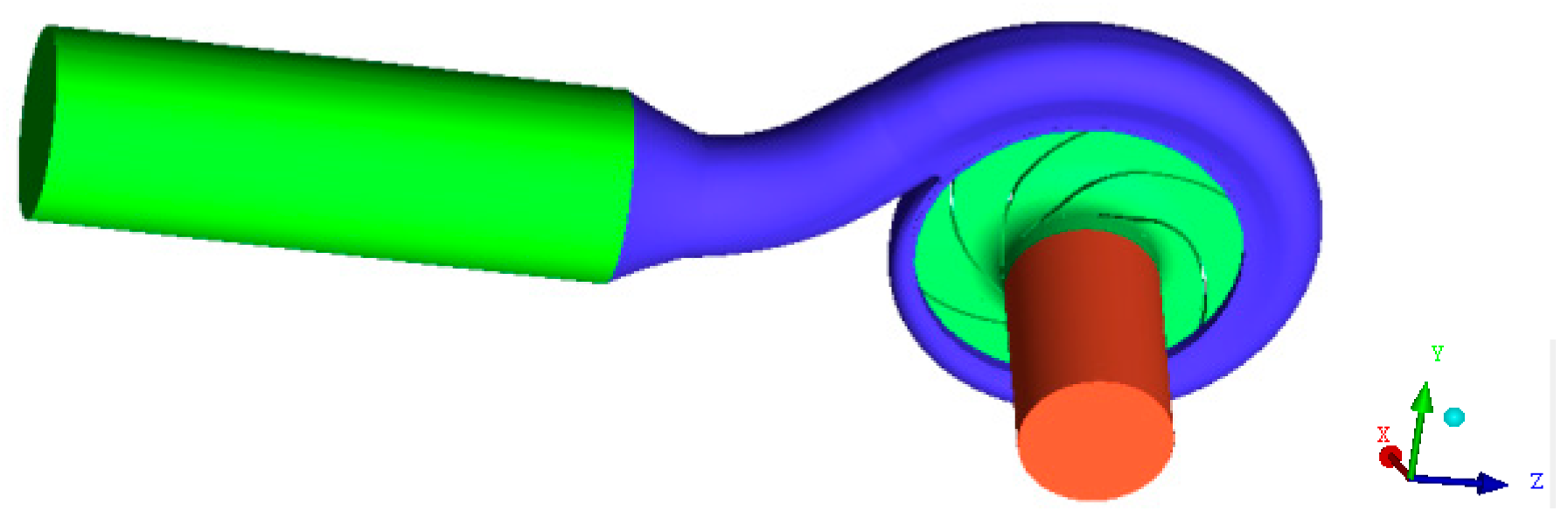
The above-mentioned algorithm is employed to numerically simulate the internal flow of the original centrifugal pump and optimized centrifugal pump. To verify the reasonableness of the algorithm used, flow in one single-stage and single suction centrifugal pump which is shown in Figure 10 was simulated under different flow rate conditions. The rated flow rate is Qd = 500 m3/h and the rated head is Hd = 53 m. Rated rotating speed is n = 1480 rpm.
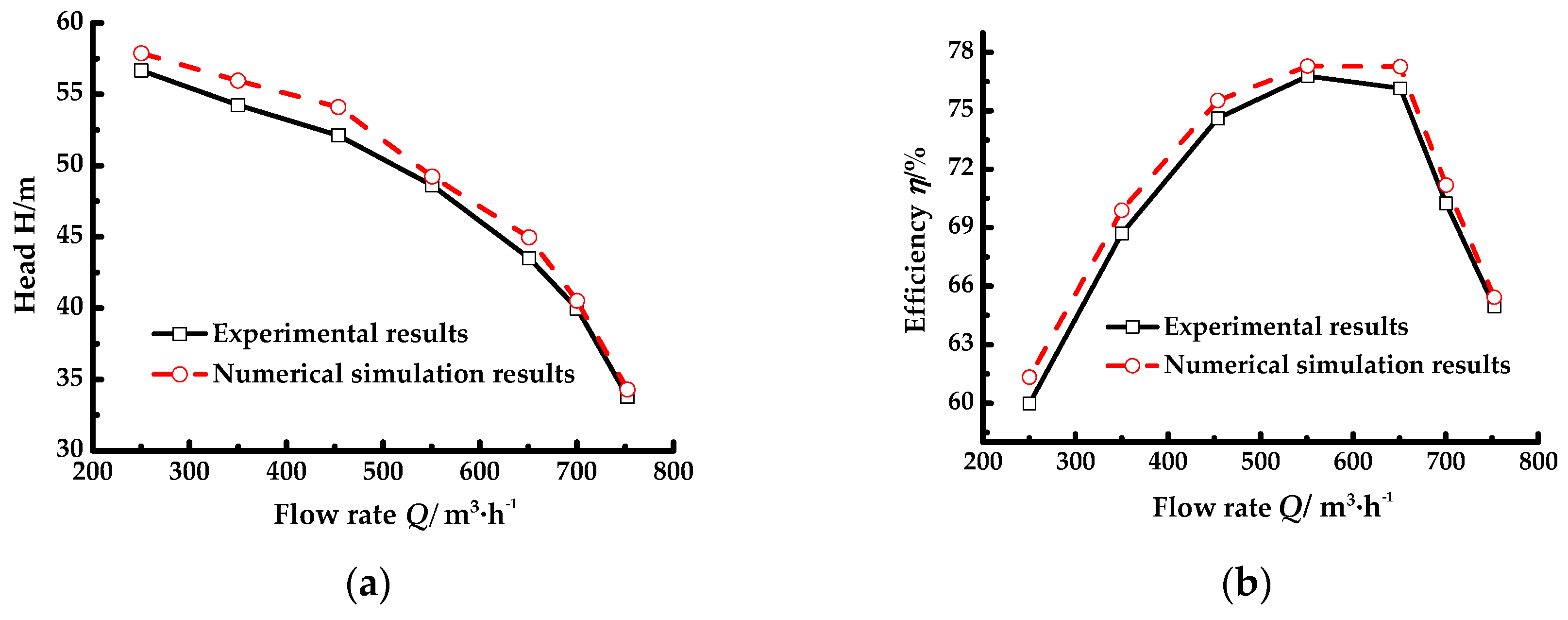
The numerical results of head and efficiency had a good agreement with the experimental results, as displayed in Figure 11. The maximum relative error of the head was less than 3.7%. The largest fractional error of the efficiency was less than 2.2%. The algorithm designed was reasonable.
6. Numerical Simulation Results Analysis
To measure the effects of blade wrap angle and blade exit angle on the performances of centrifugal pump, variations of static pressure, relative velocity, streamlines, and turbulent kinetic energy in the middle span of the impeller were analyzed under the typical flow rate conditions (low flow rate 0.6 Qd and 0.8 Qd, rated flow rate 1.0 Qd, and high flow rate 1.2 Qd and 1.5 Qd). Also, the variations of head and efficiency under the above flow rate conditions were compared.
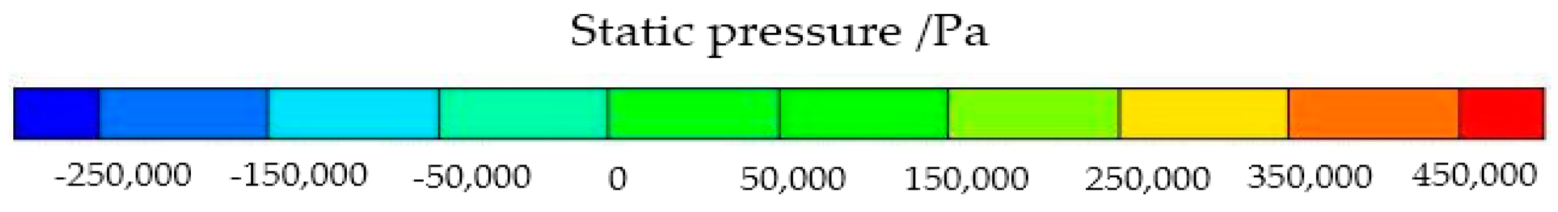
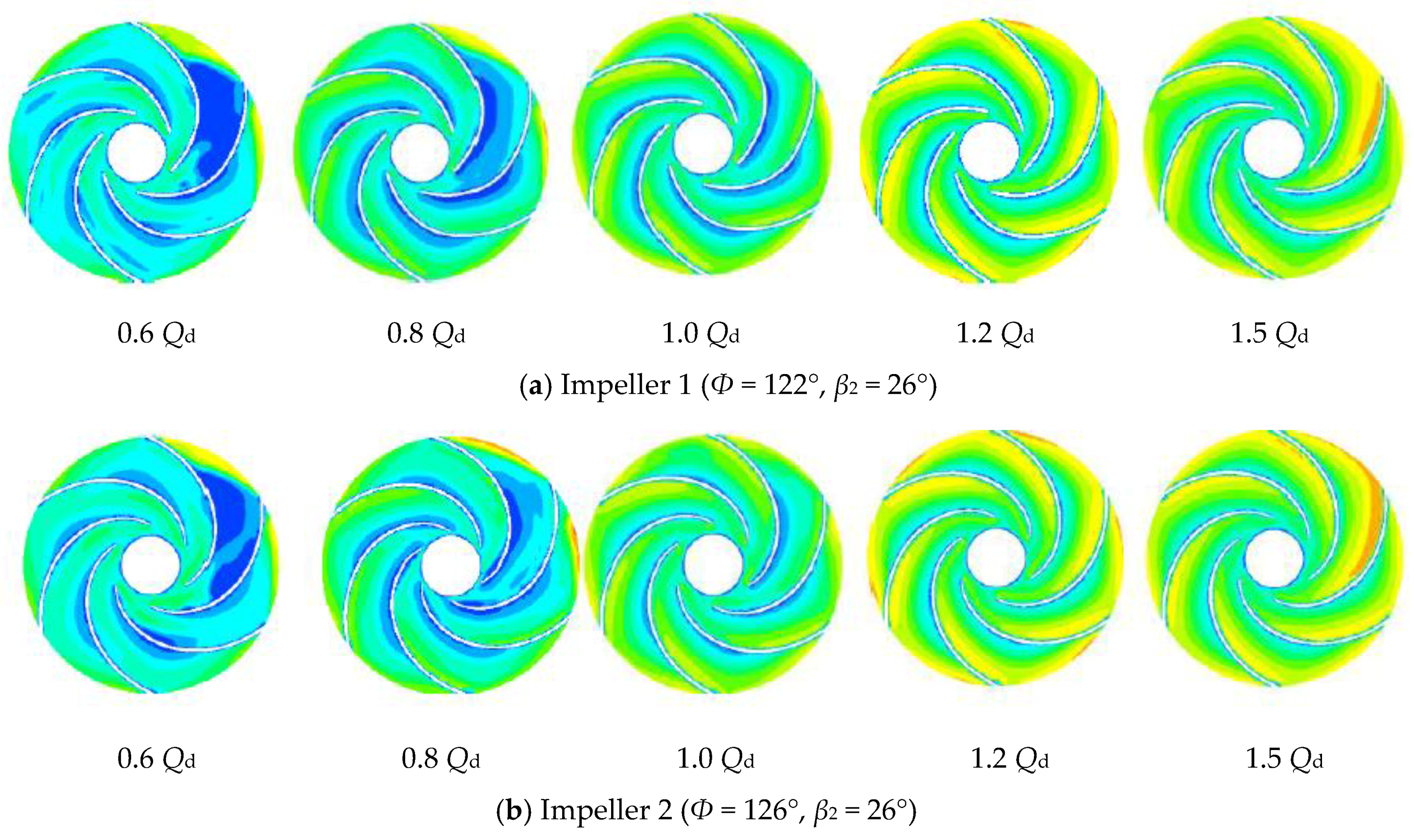
6.1. Variation of Static Pressure
The overall static pressure variation law is that static pressure in different passages distributed uniformly. Differences of static pressure in all passages were relatively small, as shown in Figure 12. At the inlet of the impeller, static pressure was the lowest. Static pressure at the outlet of the impeller was the highest. For Impellers 1–5, static pressure increased overall with the growing of flow rate. Under 0.8 Qd condition, the increase of static pressure was more manifest. At outlet, static pressure attained the maximum under 1.5 Qd condition.
Static pressure in Impellers 1, 2, and 4 fluctuated more obviously and the pressure gradient was higher, which was caused by the intense rotor-stator interaction of the impeller and the volute [25]. Volumetric loss of the centrifugal pump is severe. Thus, the centrifugal pump could not operate efficiently. For Impeller 2, under low flow rate conditions, the distribution scope of lower pressure was much larger than that of other impellers. Centrifugal pumps operating under these conditions were unstable. Compared with Impellers 1, 2, 4, and 5, the lower pressure region in Impeller 3 was much larger under 0.8 Qd and 1.2 Qd conditions, mainly caused by secondary flow. Cavitation in Impeller 3 could occur easily, which could make the performances of the centrifugal pump decrease sharply [26]. In Impeller 5, the pressure gradient was the smallest and the lower pressure region was the smallest under all flow rate conditions, proving that the optimization of Impeller 5 is the best. Impeller with Ф = 126° and blade exit angles β2 = 24° could guarantee the safety operation of the centrifugal pump.
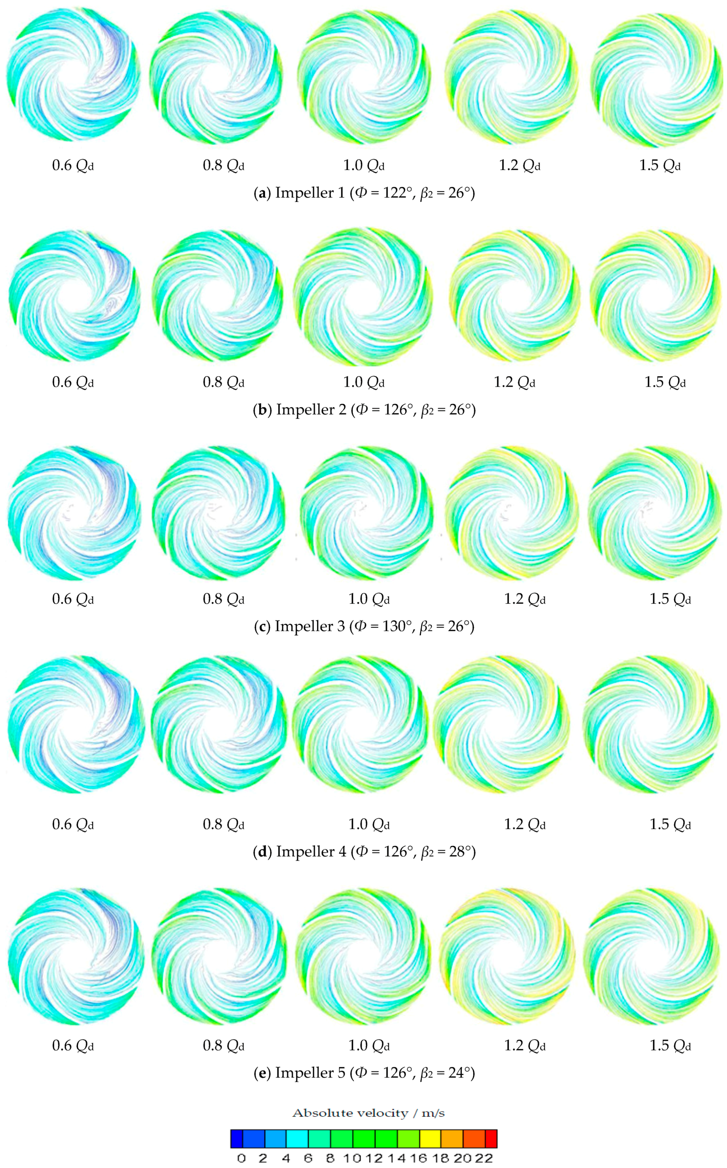
6.2. Variation of Relative Velocity
At the inlet of the impeller, the relative velocity was small. At the outlet of the impeller, the relative velocity attained the maximum, which was in agreement with the experimental and theoretical results [27]. Relative velocity in the pressure surface was much smaller than that of suction pressure. With the increase of flow rate, the low relative speed zone became smaller, as shown in Figure 13.
Under low flow rate conditions, low relative velocity zone in Impeller 5 was smaller than that of other impellers, which could guarantee the stable operation of the centrifugal pump. Velocity gradient in Impellers 1–4 was larger and the flow in these impellers was disorderly. Under rated flow rate conditions, the low speed velocity zone in Impeller 1 was the most obvious. Although differences of low speed zones of Impellers 2–5 were smaller, the zone of Impeller 5 was smaller than that of Impellers 2–4. Under high flow rate conditions, the low velocity speed zone of Impeller 5 was the smallest. Velocity sudden change did not appear. The distribution of relative velocity was uniform, which reflected that blade wrap angle Φ = 126° and blade exit angle β2 = 24° could let the centrifugal pump operate stably. The hydraulic performances of Impeller 5 were better than others.
6.3. Variation of Streamlines
Under low flow rate conditions, streamlines in Impellers 1–4 were disorder and there were manifest vortices, especially for 0.6 Qd condition, which could cause severe energy loss and secondary flow. For Impeller 2, the vortices were the most obvious, as shown in Figure 14b. The centrifugal pumps under these two flow rate conditions operated unstably, which could induce severe vibrations and noises [28] and the efficiency of the centrifugal pumps decreased. However, the streamlines in Impeller 5 under these two conditions were smooth. The secondary flow could be avoided successfully. Compared with low flow rate conditions, streamlines in rated and high flow rate conditions became smooth. However, streamlines of Impellers 1–4 were more disorder than that of Impeller 5. In Impellers 1, 2, and 4, the low speed region on the pressure surface was dramatic, which could let the flow in suction surface was faster. Energy loss in this region could be caused easily. Overall, the streamlines in Impeller 5 were the smoothest, as displayed in Figure 14e, which could result in lower energy loss. The flow separation and back flow could be controlled. The centrifugal pump could operate stably.
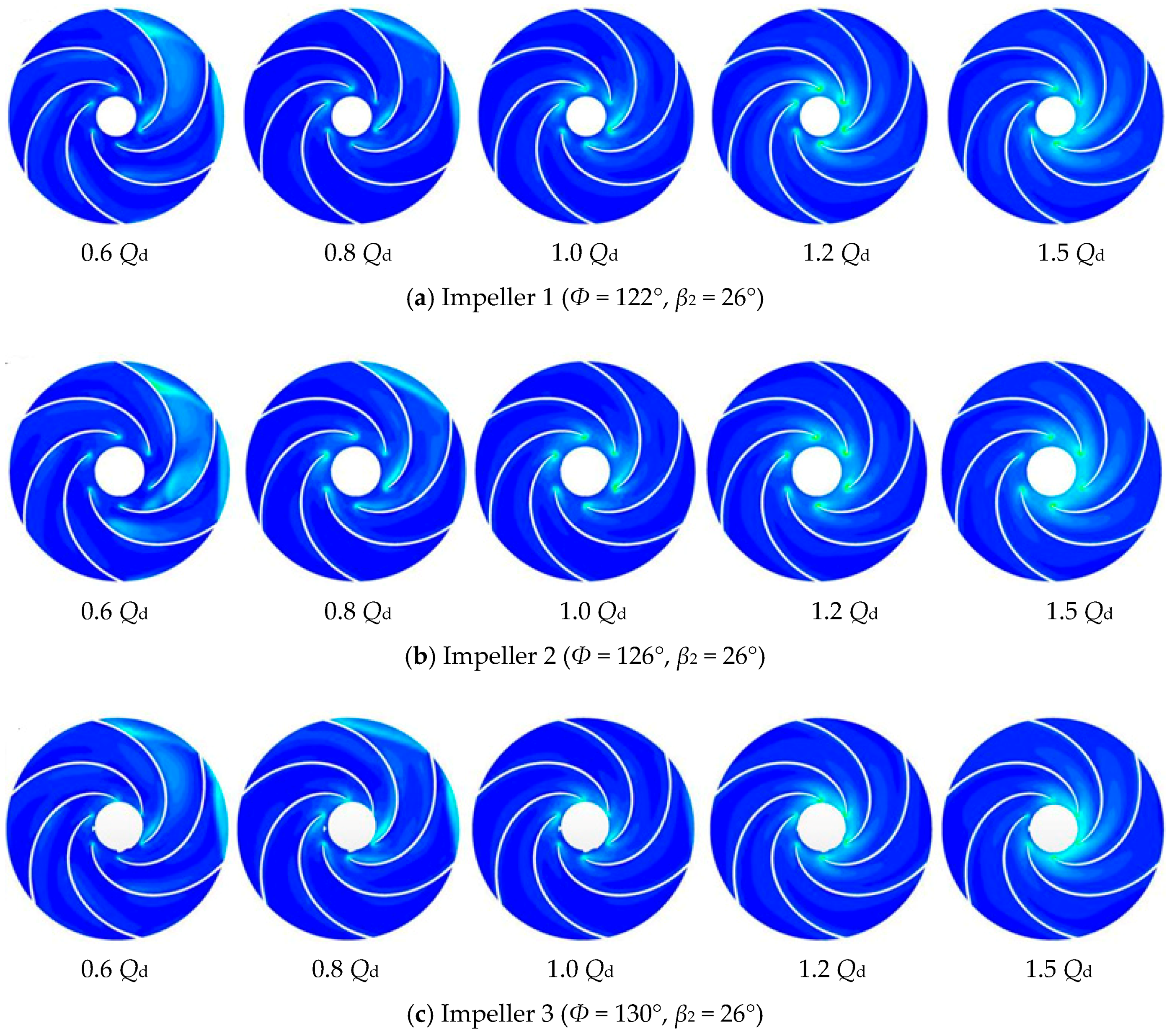
6.4. Variation of Turbulent Kinetic Energy
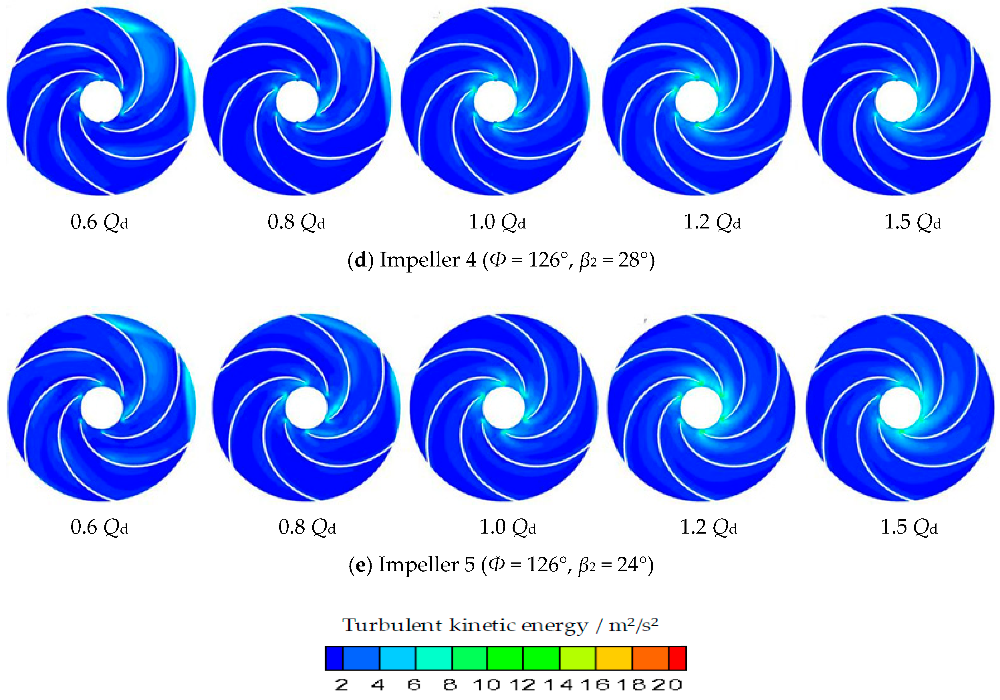
The distribution characteristics of turbulent kinetic energy in the middle span of the impeller were sharply different under diverse flow rate conditions, which were shown in Figure 15. The distribution scope became smaller gradually with the increase of flow rates. Under the 0.6 Qd condition, the distribution range of turbulent kinetic energy was the largest and under the 1.5 Qd condition, the scope was the smallest for all the impellers.
Under low flow rate conditions, the distribution scope of turbulent kinetic energy in Impeller 2 was larger than that of other impellers. Velocity vector had obvious change when water flows from the impeller to the volute. Centrifugal pump with Impeller 2 could not operate stably. Under rated flow rate conditions, the turbulent kinetic energy distribution scopes of Impellers 1, 3, and 4 were similar and they were slightly larger than that of Impeller 5. For high flow rate conditions, the distribution scope of turbulent kinetic energy was almost identical for all the impellers.
Based on the above analysis of turbulent kinetic energy and according to Equation (7), turbulent intensity l [29] of Impeller 5 was less intense than that of Impellers 1–4 overall. Thus, the energy loss in Impeller 5 was less than other impellers, which could guarantee the high transportation capacity of the centrifugal pump.
Here, vin is the inlet velocity. l is the turbulent intensity.
6.5. Variations of Head and Efficiency
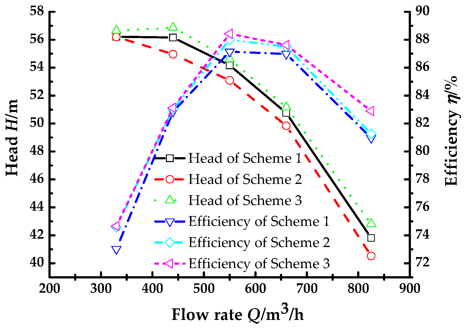
With the increase of flow rate, head decreased gradually and efficiency increased firstly then decreased, as exhibited in Figure 16. Differences of head were relatively slight. A head with Φ = 122° was higher than that of Φ = 126°. The head of the centrifugal pump with Φ = 130° was the highest one. Efficiency attained the maximum under designed flow rate. Efficiency with Φ = 130° was higher than that of Φ = 122° and 126°. Compared with Schemes 1 and 2, Scheme 3 was the optimal one.
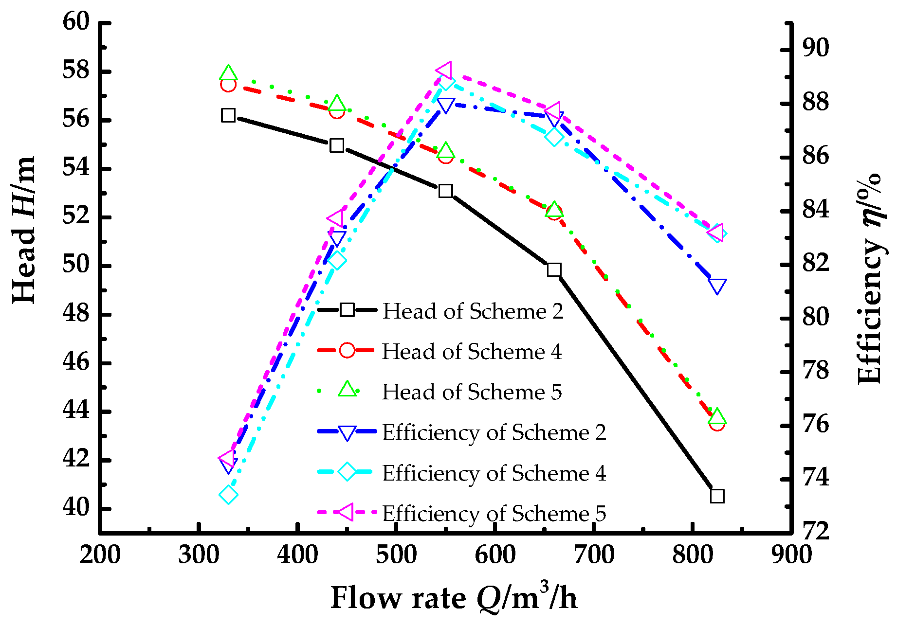
Schemes 2, 4, and 5 reflected the effects of blade exit angles on hydraulic performances of the centrifugal pump, as displayed in Figure 17. Head decreased constantly and efficiency increased firstly then decreased with the increase of flow rate. The efficiency attained the maximum under the rated flow rate. Head with β2 = 24° was slightly higher than that of β2 = 28°. Differences of head with β2 = 26° and 28° were sharp. The distinctions of efficiency were smaller. Efficiency of centrifugal pump with β2 = 24° was the highest. Compared with Schemes 2, 4, and 5, the centrifugal pump with β2 = 24° had the best hydraulic performances.
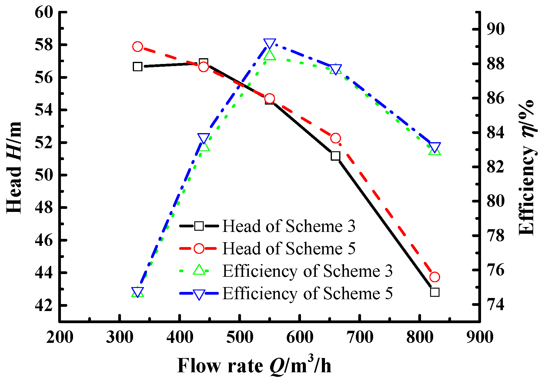
In Scheme 3, blade wrap angle Φ = 130° was the optimal one. The corresponding blade exit angle β2 = 26°. In Scheme 5, blade exit angle β2 = 24° was the best one. The corresponding blade wrap angle Φ = 126°. Head and efficiency of Scheme 5 were higher than that of Scheme 3, as shown in Figure 18. So, Scheme 5 was selected to improve the hydraulic performances of the centrifugal pump.
7. Experimental Analysis
Via numerical simulation in Part 6, Scheme 5 was determined to be the best one. The corresponding impeller was machined. Then, the performance experiments were done in the closed performance experiment rig of Shanghai Kaiquan Pump Group to verify that head and efficiency of the centrifugal pump with the Impeller 5 showing obvious improvement.
Experiment Setup
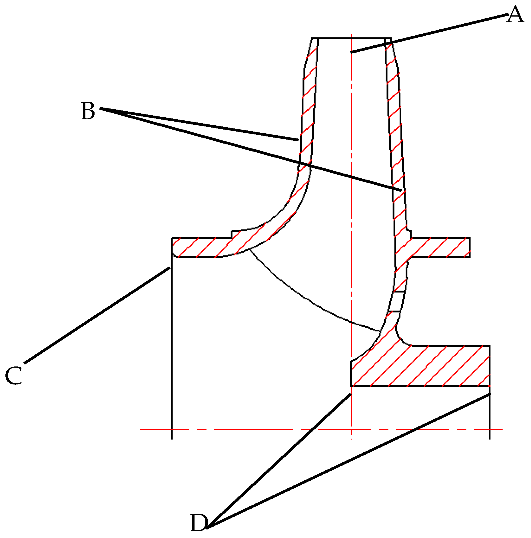
The impeller machining process was displayed in Figure 19. At the outlet of the impeller, the allowance was 5 mm, as shown in region A. Allowance of the impeller front shroud and back shroud was 3 mm, as exhibited in region B. At the inlet of the impeller, the allowance was 3 mm too, as displayed in region C. Allowance of the hub was 3 mm, as shown in region D.
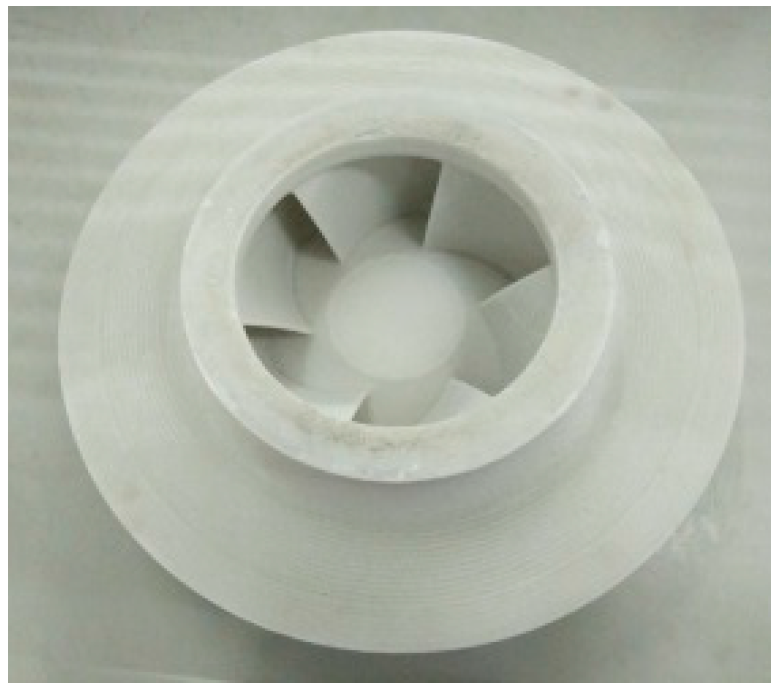
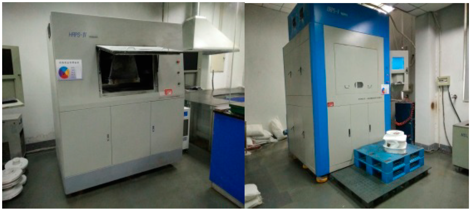
To measure the optimized design of the impeller of Scheme 5, 3D wax pattern impeller, given in Figure 20, was machined firstly in the HRPS-V rapid prototyping machine, as shown in Figure 21. Laminated object manufacturing (LOM) in this machine—which is based on the data coming from CAD laying model, CO2 laser beam, and hot pressing device—was employed to machine the 3D wax pattern impeller.
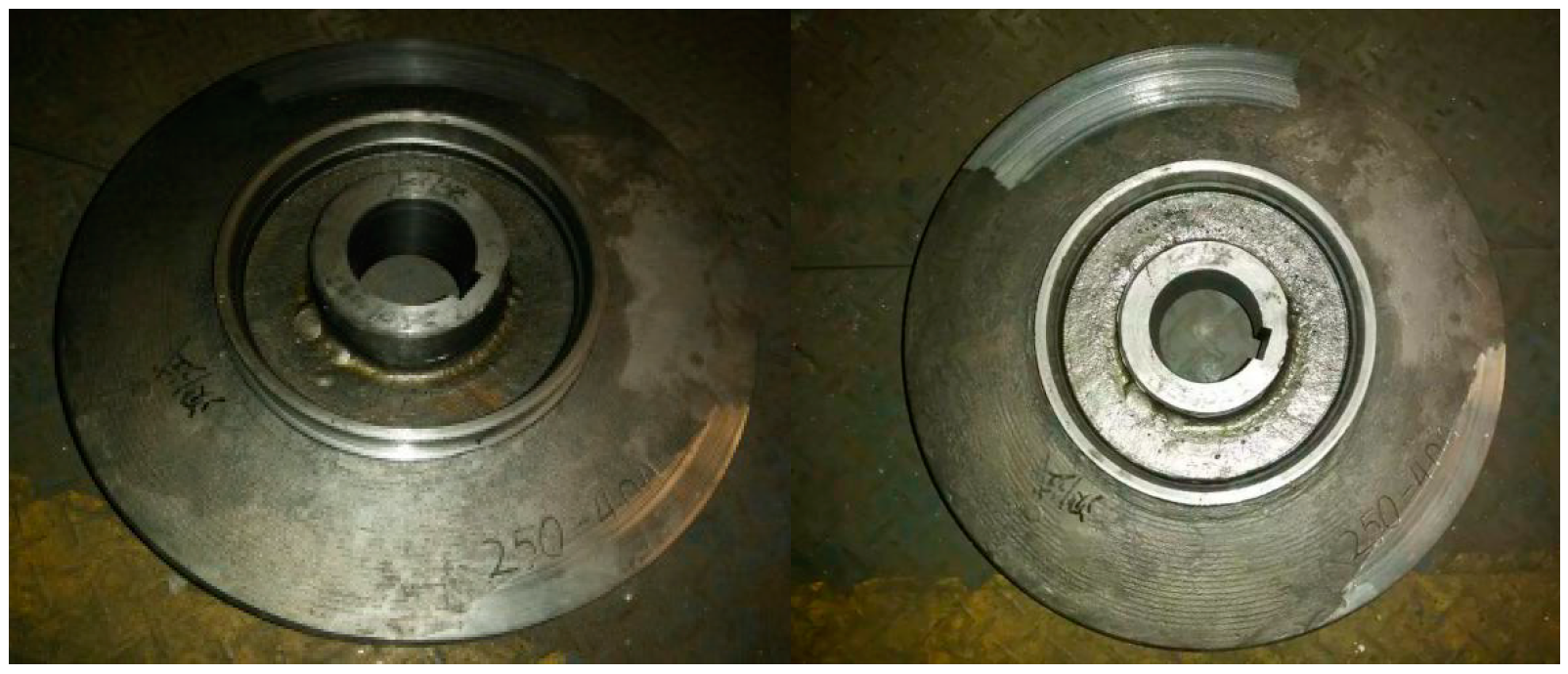
Then, the casted impeller of Scheme 5 was machined, which was displayed in Figure 22. The material was 2Cr13. To guarantee that the passages of the impeller were smooth and clean, silt particles and cast joint flash in the passages were cleaned carefully.
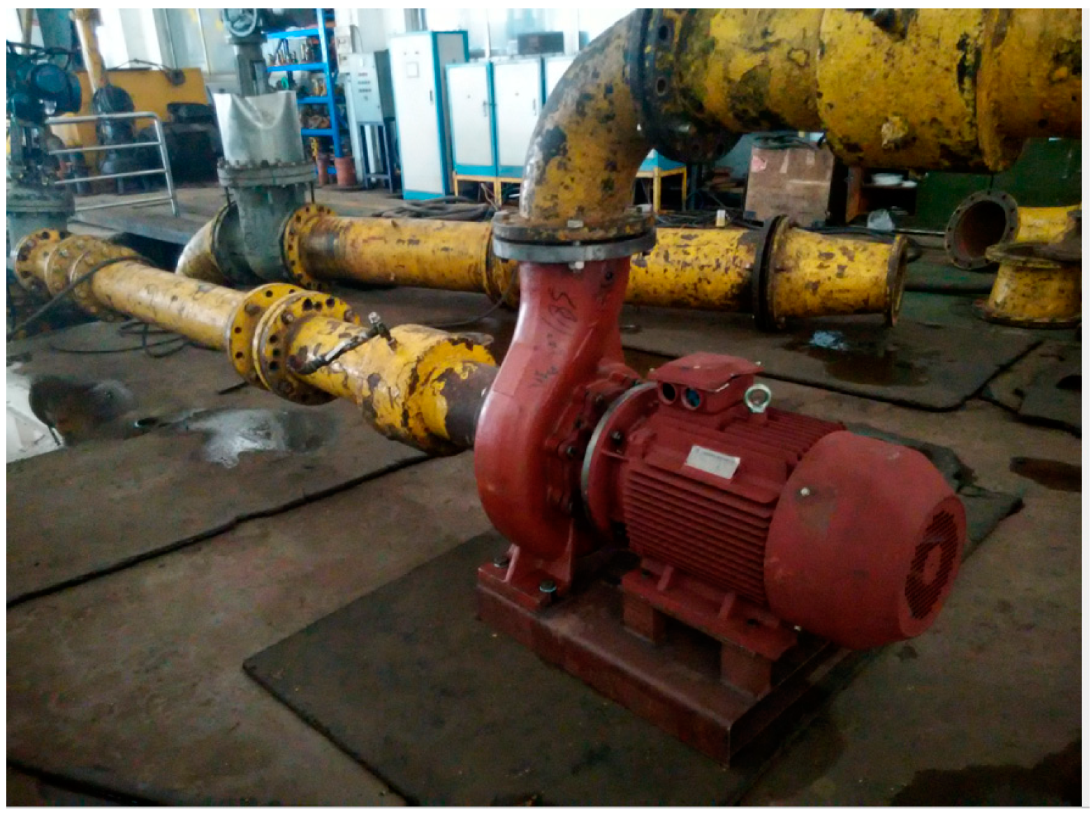
The performance experiments of the centrifugal pump were done at the closed experiment rig of Shanghai Kaiquan Pump Group. The experiment rig, given in Figure 23, includes the model centrifugal pump, suction pipes, exit pipes, pressure gauges, valves, and flow meters. The type of pressure sensor is XU12087105 (1.0, Shanghai Automation Instrumentation Co. Ltd., Shanghai, China). The type of flow meter is DN300 (1.0, Tianjin Flow Meter Co. Ltd., Tianjin, China). The type of valve is ZA2.T. All testing precisions are national grade 1 (GB3216-2005 and ISO 9906-1999).
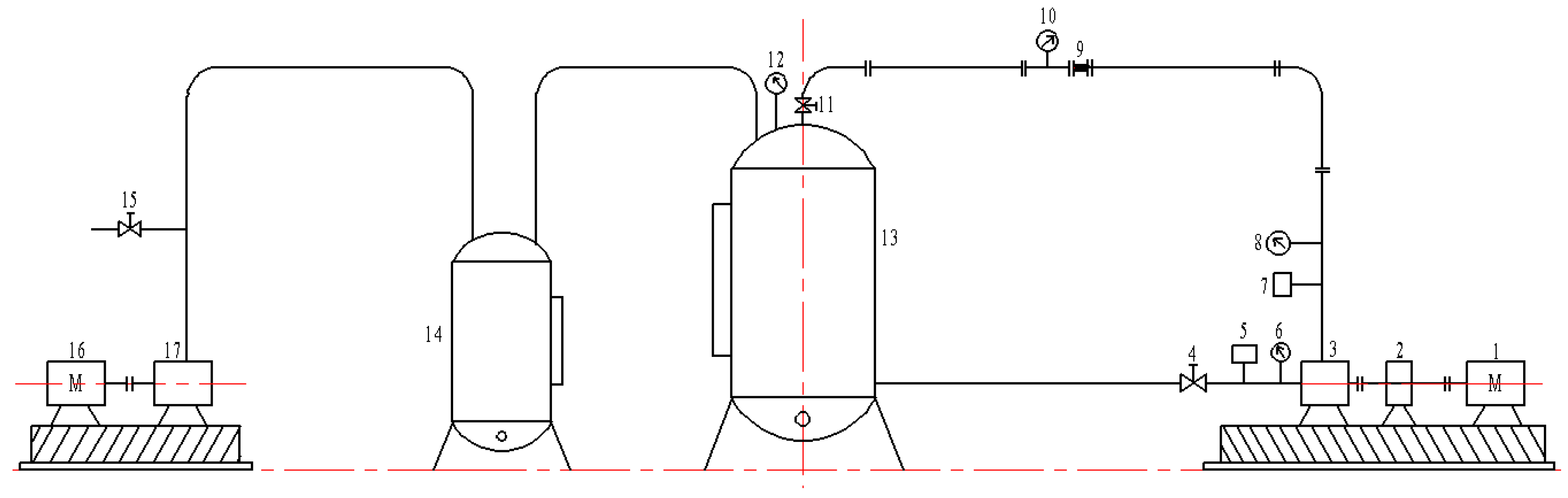
Figure 24 is the typical components of the closed performance experiment rig. It includes 16 different parts.
Via the inlet pressure Sensor 5 and the outlet pressure Sensor 7, M1 and M2 were determined. According to Equations (11) and (12), the inlet pressure and the outlet pressure of the centrifugal pump could be got.
The inlet pressure is calculated by
The outlet pressure is determined by
where h1 is the vertical height between the center of inlet pressure sensor with axial lead of the centrifugal pump. h3 is the vertical height between the center of the outlet pressure sensor with the outlet pressure port.
The inlet flow rate (Q1) and outlet flow rate (Q2) of the centrifugal pump could be measured by turbine flow meter 6 and 8, respectively.
Thus, the inlet velocity of the centrifugal pump v1 could be calculated by
The outlet velocity of the centrifugal pump v2 could be got by
Here, A1 is the inlet cross-section area. A2 is the outlet cross-section area.
Head (H) could be calculated by Equation (15)
where Z2 and Z1 are the static head.
In the performance experiment rig,
For Z2, it could be obtained by
Here, h2 is the vertical height between the center of outlet pressure sensor with axial lead of the centrifugal pump.
In the performance experiment rig,
The Equation (15) could be modified. The new form was shown in Equation (20).
Efficiency (η) could be calculated by Equation (16)
Here, P is the inlet power, which could be measured by torque and speed sensor 2.
Hydraulic performance curves of the improved centrifugal pump and the original centrifugal pump were shown in Figure 25. Experimental results indicated that head and efficiency of the improved centrifugal pump were higher than that of the original centrifugal pump. Under low flow rate condition (0.8 Qd), the head increased by 3.76 m and the efficiency increased by 3.84%. With rated flow rate condition (1.0 Qd), the head increased by 2.74 m and the efficiency increased by 5.77%, separately. For high flow rate condition (1.2 Qd), the head and efficiency increased by 2.67 m and 5.0%, respectively. The experimental results indicated that the optimized design is successful.
8. Conclusions
In this paper, effects of blade exit angle and blade wrap angle on the optimized design of the impeller were comprehensively investigated. Flows in the centrifugal pump with five different impellers under low flow rate, rated flow rate, and high flow rate were numerically simulated. Variations of static pressure, relative velocity, streamlines, and turbulent kinetic energy were analyzed. Head and efficiency of the centrifugal pump of different schemes were compared. The experimental head and efficiency of the centrifugal pump with the best impeller were compared with that of the original impeller. The main conclusions are as follows:
- (1)
- The impeller with blade wrap angle 126° and blade exit angle 24° was the best one.
- (2)
- For the best impeller, static pressure and relative velocity was the most uniform distribution. Streamlines were the smoothest and vortices did not exist. Compared with other impellers, the distribution scope of turbulent kinetic energy in the best impeller under all flow rate conditions was the smallest.
- (3)
- For the centrifugal pump with optimized impeller, head and efficiency were higher than that of the original pump. With low flow rate (0.8 Qd), the head and efficiency increased by 3.76 m and 3.84%. With rated flow rate, the head and efficiency increased by 2.74 m and 5.77%. With high flow rate (1.2 Qd), the head and efficiency increased by 2.67 m and 5.0%.
Author Contributions
X.H. and Y.K. presented the optimal scheme and designed the experiments. X.H. and D.L. made the numerical simulation and performed the experiment. W.Z. analyzed the data. X.H. wrote the paper.
Acknowledgments
This research is financially supported by the National Key Basic Research Program of China (no. 2014CB239203), the National Natural Science Foundation of China (no. 51474158), and the Hubei Provincial Natural Science Foundation of China (no. 2016CFA088). We deeply acknowledge the help of Hubei Key Laboratory of Waterjet Theory and New Technology, School of Energy and Power Engineering of Lanzhou University of Technology, and Shanghai Kaiquan Group.
Conflicts of Interest
The authors declare no conflict of interest.
References
- Yedidiah, S. Centrifugal Pump User’s Guidebook: Problems and Solutions; Springer Group: Berlin, Germany, 1996. [Google Scholar]
- Gülich, J.F. Centrifugal Pumps; Springer Group: Berlin, Germany, 2008. [Google Scholar]
- Karassik, I.J. Centrifugal Pump Clinic; Taylor Francis Inc.: Oxford, UK, 1989. [Google Scholar]
- Tuzson, J. Centrifugal Pump Design; Wiley-Interscience: Washington, DC, USA, 2000. [Google Scholar]
- Grist, E. Cavitation and the Centrifugal Pump: A Guide for Pump Users; Taylor Francis Inc.: Oxford, UK, 1998. [Google Scholar]
- Lobanoff, V.S.; Ross, R.R. Centrifugal Pump: Design and Application; Gulf Professional Publishing: Houston, TX, USA, 1992. [Google Scholar]
- Girdhar, P.; Moniz, O. Practical Centrifugal Pumps. Design, Operation, Maintenance; Newnes: Amsterdam, The Netherlands, 2005. [Google Scholar]
- Wu, Z.H. Three-dimensional turbomachine flow equations expressed with respect to non-orthogonal curvilinear coordinates and non-orthogonal velocity components and methods of solution. J. Mech. Eng. 1979, 15, 1–23. [Google Scholar]
- Zhang, Z.H. Streamline similarity method for flow distribution and shock losses at the impeller inlet of the centrifugal pump. J. Hydrodyn. 2018, 30, 140–152. [Google Scholar] [CrossRef]
- Pei, J.; Wang, W.J.; Yuan, S.Q.; Zhang, J.F. Optimization on the impeller of a low-specific-speed centrifugal pump for hydraulic performance improvement. Chin. J. Mech. Eng. 2017, 29, 992–1002. [Google Scholar] [CrossRef]
- Tan, L.; Zhu, B.S.; Cao, S.L.; Bing, H.; Wang, Y.M. Influence of blade wrap angel on centrifugal pump performance by numerical and experimental study. Chin. J. Mech. Eng. 2014, 27, 171–177. [Google Scholar] [CrossRef]
- Kim, J.H.; Lee, H.C.; Kim, J.H.; Kim, S.; Yoon, J.Y.; Choi, Y.S. Design techniques to improve the performance of a centrifugal pump using CFD. J. Mech. Sci. Technol. 2015, 29, 215–225. [Google Scholar] [CrossRef]
- Stepanoff, A.J. Centrifugal and Axial Pump: Theory, Design and Application; John Wiley Sons Inc.: Hoboken, NJ, USA, 1986. [Google Scholar]
- Yang, A.L.; Lang, D.P.; Li, G.P.; Chen, E.Y.; Dai, R. Numerical research about influence of blade outlet angel on flow-induced noise and vibration for centrifugal pump. Adv. Mech. Eng. 2015, 6, 1–11. [Google Scholar]
- Heo, M.W.; Kim, J.H.; Seo, T.W.; Kim, K.Y. Aerodynamic and aeroacoustic optimization for design of a forward-curved blades centrifugal fan. Proc. Inst. Mech. Eng. Part A J. Power Energy 2017, 230, 154–174. [Google Scholar] [CrossRef]
- Guan, X.F. Modern Pumps Theory and Design; China Astronautic Publishing House: Beijing, China, 2011. (In Chinese) [Google Scholar]
- Bai, Y.X.; Kong, F.Y.; Yang, S.S.; Chen, K.; Dai, T. Effect of blade wrap angel in hydraulic turbine with forward-curved blades. Int. J. Hydrogen Energy 2017, 42, 18709–18717. [Google Scholar] [CrossRef]
- Wang, W.J.; Pei, J.; Yuan, S.Q.; Zhang, J.F.; Yuan, J.P.; Xu, C.Z. Application of different surrogate models on the optimization of centrifugal pump. J. Mech. Sci. Technol. 2016, 30, 567–574. [Google Scholar] [CrossRef]
- Zhou, L.; Shi, W.D.; Wu, S.Q. Performance optimization in a centrifugal pump impeller by orthogonal experiment and numerical simulation. Adv. Mech. Eng. 2013, 6, 1–11. [Google Scholar] [CrossRef]
- Nelik, L. Centrifugal and Rotary Pumps: Fundamentals with Applications; CRC Press: London, UK, 1999. [Google Scholar]
- Li, W.G.; Su, F.Z.; Ye, Z.M.; Xia, D.L. Experiment on effect of blade pattern on performance of centrifugal oil pumps. Chin. J. Appl. Mech. 2002, 19, 31–34. [Google Scholar] [CrossRef]
- Lohner, R. Applied Computational Fluid Dynamics Techniques: An Introduction Based on Finite Element Methods; John Wiley & Sons: Hoboken, NJ, USA, 2008. [Google Scholar]
- Yakhot, V.; Orzag, S.A. Renormalization group analysis of turbulence: Basic theory. J. Sci. Comput. 1986, 1, 3–51. [Google Scholar] [CrossRef]
- Zhou, L.; Shi, W.D.; Li, W.; Agarwal, R. Numerical and experimental study of axial force and hydraulic performance in a deep-well centrifugal pump with different impeller rear shroud radius. J. Fluid Eng. 2013, 135, 749–760. [Google Scholar] [CrossRef]
- Posa, A.; Lippolis, A. A LES investigation of off-design performance of a centrifugal pump with variable-geometry diffuser. Int. J. Heat Fluid Flow 2018, 70, 299–314. [Google Scholar] [CrossRef]
- Chen, H.X.; He, J.W.; Liu, C. Design and experiment of the centrifugal pump impellers with twisted inlet vice blades. J. Hydrodyn. 2017, 29, 1085–1088. [Google Scholar] [CrossRef]
- Yang, S.L.; Kong, F.Y.; Chen, H.; Su, X.H. Effects of blade wrap angel influencing a pump as turbine. J. Fluid Eng. 2012, 134, 1–8. [Google Scholar] [CrossRef]
- Cheah, K.W.; Lee, T.S.; Winoto, S.H.; Zhao, Z.M. Numerical flow simulation in a centrifugal pump at design and off-design conditions. Int. J. Rotating Mach. 2007, 2, 1–9. [Google Scholar] [CrossRef]
- Ferziger, J.H.; Peric, M. Computational Methods for Fluid Dynamics; Springer Group: Berlin, Germany, 2002. [Google Scholar]
Figure 1.
Two-dimensional model of the impeller.

Figure 2.
Speed triangle.

Figure 3.
Flow chart of the optimized design of the impeller.

Figure 4.
Physical model of the blades.

Figure 5.
Physical model of the centrifugal pump.

Figure 6.
Physical model of the impeller.

Figure 7.
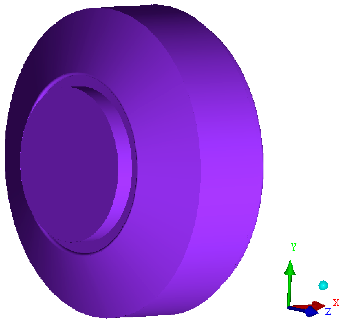
Chamber of the centrifugal pump.

Figure 8.
Meshes of the computational domain of the centrifugal pump.


Figure 9.
Meshes independence.

Figure 10.
Experimental centrifugal pump.

Figure 11.
Comparison of the hydraulic performances of centrifugal pump. (a) Head (H)-flow rate (Q); (b) Efficiency (η)-flow rate (Q).
Figure 11.
Comparison of the hydraulic performances of centrifugal pump. (a) Head (H)-flow rate (Q); (b) Efficiency (η)-flow rate (Q).

Figure 12.
Variation of static pressure in different impellers.


Figure 13.
Variation of absolute velocity in different impellers.


Figure 14.
Variation of streamlines in different impeller.

Figure 15.
Variation of turbulent kinetic energy in different impellers.


Figure 16.
Hydraulic performances of the centrifugal pump with different blade wrap angles.

Figure 17.
Hydraulic performances of the centrifugal pump with different blade exit angles.

Figure 18.
Hydraulic performances of Schemes 3 and 5.

Figure 19.
The machining process of the impeller.

Figure 20.
3D wax pattern.

Figure 21.
HRPS-V rapid prototyping machine.

Figure 22.
The casted impeller.

Figure 23.
Performance experiment rig.

Figure 24.
Components of the closed performance experiment rig. 1–electric motor; 2–torque and speed sensor; 3–centrifugal pump; 4–sluice valve; 5–inlet pressure sensor; 6–turbine flow meter; 7–outlet pressure sensor; 8–turbine flow meter; 9–expansion joint; 10–turbine flow meters; 11–regulating valve; 12–turbine flow meters; 13–cavitation tank; 14–separation tank of vapor and water; 15–ball valve; 16–electric motor; 17–vacuum pump.

Figure 25.
Hydraulic performance of improved and original centrifugal pump.


Table 1.
Optimized schemes of the blade profile.
| Scheme | 1 | 2 | 3 | 4 | 5 |
|---|---|---|---|---|---|
| Φ | 122° | 126° | 130° | 126° | 126° |
| β2 | 26° | 26° | 26° | 28° | 24° |
Table 2.
Geometric parameters of the impeller and volute
| Parameter | Value |
|---|---|
| Impeller inlet diameter D1, mm | 200 |
| Impeller outlet diameter D2, mm | 420 |
| Impeller exit width b2, mm | 34 |
| Number of blade Z | 6 |
| Base diameter of the volute D3, mm | 435 |
| Volute inlet width b3, mm | 72 |
| Volute outlet diameter D4, mm | 250 |
Table 3.
Mesh number and quality
| Front and Back Chamber | Volute | Suction Pipe | Exit Pipe | |
|---|---|---|---|---|
| Mesh number | 934,607 | 2,238,179 | 498,506 | 327,624 |
| Mesh quality | >0.4 | >0.4 | >0.8 | >0.8 |
© 2018 by the authors. Licensee MDPI, Basel, Switzerland. This article is an open access article distributed under the terms and conditions of the Creative Commons Attribution (CC BY) license (http://creativecommons.org/licenses/by/4.0/).
Share and Cite
MDPI and ACS Style
Han, X.; Kang, Y.; Li, D.; Zhao, W. Impeller Optimized Design of the Centrifugal Pump: A Numerical and Experimental Investigation. Energies 2018, 11, 1444. https://doi.org/10.3390/en11061444
AMA Style
Han X, Kang Y, Li D, Zhao W. Impeller Optimized Design of the Centrifugal Pump: A Numerical and Experimental Investigation. Energies. 2018; 11(6):1444. https://doi.org/10.3390/en11061444
Chicago/Turabian StyleHan, Xiangdong, Yong Kang, Deng Li, and Weiguo Zhao. 2018. "Impeller Optimized Design of the Centrifugal Pump: A Numerical and Experimental Investigation" Energies 11, no. 6: 1444. https://doi.org/10.3390/en11061444
Note that from the first issue of 2016, this journal uses article numbers instead of page numbers. See further details here.