Achieving relativistically intense X-rays from structured plasma lens
 Peng Chen
 Taiwu Huang*
 - Shenzhen Key Laboratory of Ultraintense Laser and Advanced Material Technology, Center for Advanced Material Diagnostic Technology, College of Engineering Physics, Shenzhen Technology University, Shenzhen, China
Focusing of high-power X-rays is still a great challenge and the intensity of X-ray attained in existing focusing schemes is still far below the relativistic threshold. Here, we propose that solid density plasma lens can potentially focus X-ray lasers at very high power levels. The interaction of high-power X-ray laser with solid-density plasmas is systematically studied. It is theoretically shown that there exists a certain range of wavelengths for X-ray lasers that can be focused in solid-density plasmas when the input power and plasma density are determined. To avoid the essential laser-plasma instabilities and obtain high-gain intensity amplification for X-ray, we design concave structured plasma lens. Particle-in-cell simulation results show that such regime can effectively avoid the instabilities and focus X-ray of micrometer-sized spot and multi-TW power, and thus lead to the generation of relativistic intensity X-ray. The parameters of the concave structures and the effects of quantum electrodynamics are also discussed and it indicates that our scheme is quite robust. We further demonstrate that the relativistic X-ray laser interacting with thin-foil leads to high-quality attosecond electron bunches.
Introduction
The rapid development of high-intensity lasers has opened the gate for many research areas, such as strong field physics, laser plasma physics, quantum electrodynamics, and laboratory astrophysics. Recently, a 4 PW infrared laser with a world-record intensity greater than 1023 W/cm2 was first reported [1]. Many countries in the world are now building tens or even hundreds of petawatt level infrared lasers, which are supposed to deliver much higher laser intensities than that presently available. As is well known, the average intensity of the laser is
Now it becomes critically difficult to realize extremely intense lasers of infrared wavelength, say the Schwinger limit
So far, many schemes have been proposed to achieve multi-TW of X-ray pulses on free-electron laser (FEL) facilities [8–11]. In addition, high-harmonic generation (HHG) from solid surface plasma [12–14] can produce a single X-ray pulse with very high power of 100 TW under the existing laser parameters [14]. However, these X-ray sources both have very large focal spot, ranging from several to even hundreds of microns, which are much larger than the wavelength. Now the optical technology can focus hard X-ray to less than 10 nm [15,16], but the focal size is still about two orders of magnitude higher than the wavelength. In addition, with the enhancing power, optical elements may be easily damaged. Thus, the focused X-ray laser intensity is still far below the relativistic threshold [17,18], which greatly restricts the range of science that can be explored.
Recently, plasma optics has become a research frontier in the control of high-power lasers due to the lack of damage thresholds as plasma is already a broken media and can tolerate ultrahigh laser intensities. For example, low-density and near-critical density plasmas have already been used for laser focusing [19,20], polarization manipulation[21,22], Raman and Brillouin amplification [23,24], pulse shaping [25], pulse guidance [26,27], frequency modulation [28,29], etc. The research on the modulation of ultra-intense laser by micro-nano plasma has also become a noteworthy direction recently. Habara et al. proposed to use a concave surface plasma with micro/nano dimensions to reflect and focus the ultra-strong laser and increase the yield of high-energy particles [30]. However, it is noted that the current researches are mainly focused on the infrared laser. In order to control the much shorter X-ray laser, in principle it requires solid-density plasmas, which now can be produced by isochoric heating of solid-density matter through intense X-rays, frequency doubling laser, and intense particle beams [31–33].
In this paper, we extend plasma optics to X-ray wavelengths and propose to use solid-density plasma to focus multi-TW X-ray pulse to solve the focusing problem of high power X-ray. It is theoretically shown that there is a certain range of wavelengths for X-ray laser that can be focused in solid-density plasmas when the input power and plasma density are determined. However, for the presently available X-ray pulses with micrometer-sized spot, they suffer from disruptive multi-dimensional instabilities when propagating in plasmas, hindering the focusing of very high power X-rays to relativistic intensities. In order to solve this critical issue, we propose a novel and robust approach using a concave plasma lens to realize an extremely intense X-ray laser of relativistic intensities. Such regime is verified through three-dimensional particle-in-cell simulations, which show that TW-level X-ray pulses can be efficiently focused to a spot on wavelength scale while keeping high quality spatiotemporal profiles. It is further shown that such relativistic X-ray laser can drive high-quality attosecond electron bunches when interacting with a thin-foil target.
X-ray focusing in solid-density plasmas
When laser propagates in underdense plasma, the distribution of plasma refractive index changes due to the laser ponderomotive force and the relativistic effects of electron motion in laser electric field. In this case, the refractive index of plasma can be expressed as
When the wavelength is lower than the lower wavelength limit of Eq. 1, the focusing effect provided by plasma is smaller than the diffraction of the Gaussian beam itself, so the pulse will not focus. On the other hand, when the wavelength is larger than the upper wavelength limit, the pulse cannot enter into the plasma and will be reflected. Only in the wavelength range can the pulse travel through the plasma and become self-focused. As shown in Figure 1A, the red and blue surfaces represent the upper and lower limit of wavelength, respectively. The upper limit of X-ray wavelength depends only on ne and is inversely proportional to
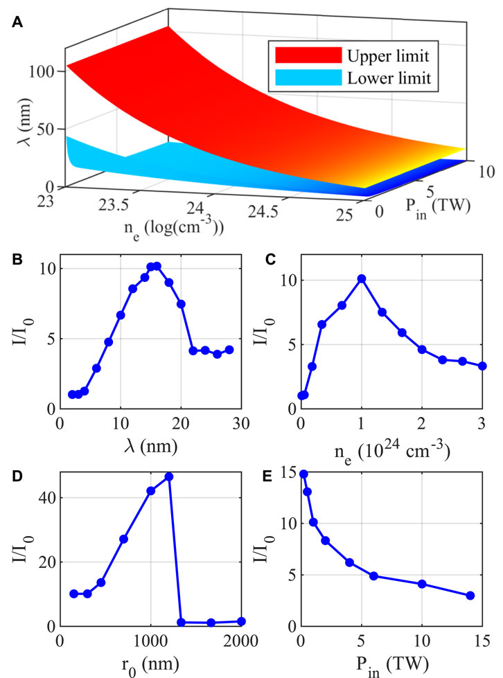
FIGURE 1. Parametric dependence of X-ray pulse self-focusing in solid density plasma. (A) The theoretical upper and lower wavelength limits of self-focusing vary with plasma density and input power. (B–E) 2D simulation results show that the intensity amplification varies with (B) wavelength, (C) density, (D) initial focal spot radius and (E) initial power. The basic parameters are Pin = 1 TW, λ = 15 nm, r0 = 150 nm, ne = 1024 cm−3.
To demonstrate the parametric dependence of X-ray focusing in solid-density plasmas, a series of two-dimensional particle-in-cell simulations were conducted using the EPOCH code [35]. In the simulations, the X-ray lasers are of input power Pin = 1 TW, wavelength λ = 15 nm, focal spot radius r0 = 10λ, and the initial plasma density is ne = 1024 cm−3. These parameters correspond to a wavelength range of 4.39–33.17 nm according to Eq. 1. The moving simulation box is of size 60λ × 60λ in x × y space, with 600 × 600 grids and ten particles per cell. The corresponding timestep is equal to 0.95△x/c to meet the Courant-Friedrichs-Lewy (CFL) convergence condition, where △x refers to the spatial resolution. The X-ray laser is assumed to have a Gaussian profile with duration of τ0 = 10TL, where TL is the laser period, and is incident along the x direction and enters a solid-density plasma with density of ne at x = 10λ. The amplification factors I/I0 of laser peak intensity are obtained from simulations for different parameters, which are shown in Figures 1B–E. In these simulations, only one single parameter is changed and the others are kept same as the above setup.
Figure 1B confirms the wavelength range of Eq. 1. When the X-ray wavelength is smaller than 4 nm, the input laser power is lower than the critical power, and the laser pulse quickly diffuses as soon as it enters the plasma. When the X-ray wavelength is larger than the lower limit, the amplification factor first increases and then decreases as the wavelength increases, which indicates that there exists an optimal wavelength for fixed laser power and plasma density. When the wavelength is smaller than the optimal one, the amplification factor of laser intensity can be roughly estimated as
Figure 1C shows that for fixed laser parameters, there also exists an optimal plasma density for efficient X-ray focusing. The underlying physical reason is similar with the above analyses. When the density is lower than the optimal one,
In order to demonstrate the LPI instabilities more clearly, we conduct 3D simulations with r0 = 1,000 nm and Pin = 2, 6, 10 and 20 TW. As shown in Figure 2 and Table 1, when Pin = 2 TW, the X-ray pulse can be focused to a small point, and I/I0 can be increased to 95.3 at 37.5 fs. However, for Pin = 6 TW or higher laser powers, the X-ray pulse is subjected to multi-dimensional instabilities, including the longitudinal modulation by plasma waves, transverse filamentation due to uneven density disturbance, and photon deceleration along the central axis. These instabilities cause the pulse to be destroyed before it is effectively focused. As a result, the amplification factor is reduced to I/I0 = 32.5 for Pin = 6 TW and would further decrease with the increasing input power. In this sense, it is challenging to achieve X-ray pulses focusing at high-power levels by the solid-density plasma lens.
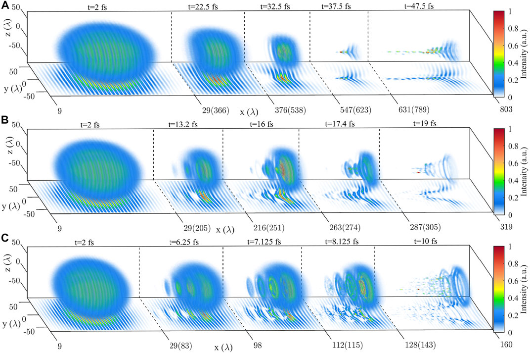
FIGURE 2. Instabilities development of X-ray pulses with different initial powers. (A) Pulse profiles at t = 2, 22.5, 32.5, 37.5 and 47.5 fs when Pin = 2 TW. (B) Pulse profiles at t = 2, 13.2, 16, 17.4 and 19 fs when Pin = 6 TW. (C) Pulse profiles at t = 2, 6.25, 7.125, 8.125 and 10 fs when Pin = 20 TW. The (x, z) planes are the section at z = 0. Color represents intensity. The intensity at each moment is normalized by its maximum intensity.
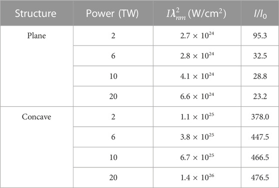
TABLE 1. Focusing intensity and amplification of plane and concave plasma with different power.
X-ray focusing by concave plasma lens
To solve the above critical issue, a concave plasma lens is proposed. Such concave structures in the simulation can be set as S = ρr2+L, where ρ is a concave coefficient (with respect to the degree of curvature of the concave), and L is the length of the plane plasma slab in front of the concave structure, as shown in Figure 3B. Concave plasma lens has prominent advantages on realizing efficient focusing of very high power X-rays with large spot radius. On the one hand, the shortened interaction length in the central region can greatly avoid the LPI instabilities. On the other hand, effective focusing can be achieved when laser exits from the concave structure, which shall be discussed later. Figure 3 show the evolution of X-ray pulse profiles through the concave structure and the plasma distribution of concave for Pin = 6 TW, r0 = 1,000 nm, ρ = 2.25 × 10⁶ m−1, L = 160λ, and ne = 1024 cm−3. It is shown that the pulse begins to enter the backside vacuum at around 10 fs, where the pulse is not yet strongly modulated by the plasma wave. Due to the focusing effect caused by the concave structure, the pulse can be focused to wavelength scale spot and keep well-defined profiles, resulting in a maximum intensity of I ≈ 1.7 × 10²³ W/cm2 at 20 fs, and a maximum amplification factor of I/I0 = 447.5. To compare X-ray intensities of different wavelengths,
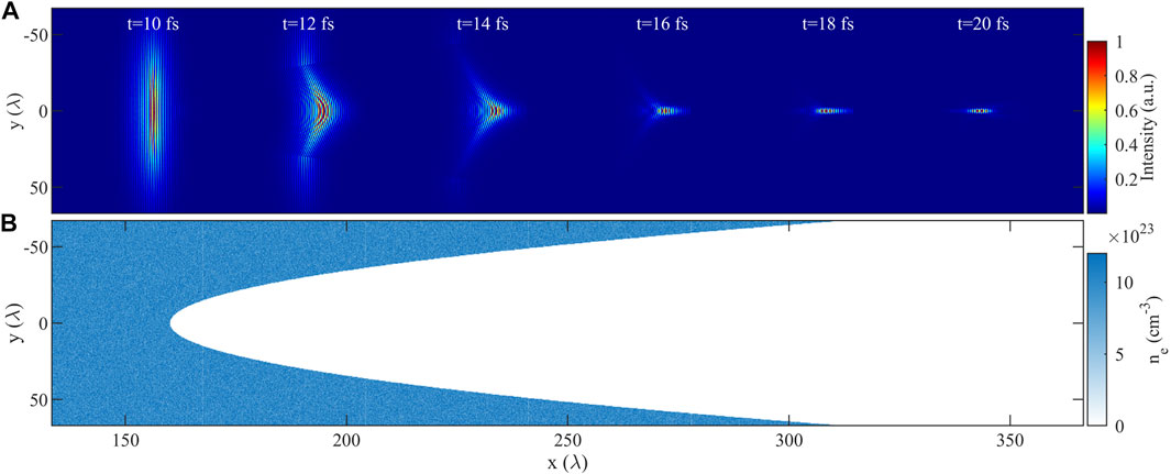
FIGURE 3. 3D simulation results with concave structure S = 2.25 × 10⁶r2+160λ at the (x, y) plane with z = 0. (A) Intensity distributions at t = 10, 12, 14, 16, 18, and 20 fs during pulsed focusing of a concave plasma lens. The intensity at each moment is normalized by its maximum intensity. (B) Plasma distribution with concave structures.
In addition, the concave structure can also extend the wavelength range of X-ray focusing in solid-density plasmas. In particular, even when the input power is less than the critical power, or the wavelength is less than the lower wavelength limit in Eq. 1, the X-ray pulse can still be focused with a concave plasma lens. For example, in the case of Pin = 50 GW and ne = 1024 cm−3, which corresponds to a lower wavelength limit of 19.6 nm, our 2D simulation shows that even with a wavelength of 15 nm (smaller than the lower wavelength limit), the pulse intensity can still be increased by 16.7 times in the case with a concave plasma lens. Thus, the concave plasma lens works for a wider range of wavelength than that for a plane plasma target. In addition, we also consider additional simulation for longer pulse widths (FWHM = 5 fs), it is shown that the concave plasma lens can still effectively focus the pulse, increase the peak intensity, and maintain a well pulse profile while keeping the pulse energy same with the short pulse case.
Effects of concave parameters on X-ray focusing
In the following, we will consider the parameters of concave structure that may affect the X-ray focusing process. Firstly, the concave coefficient ρ is considered. Figure 4A shows the distributions of concave structures for different values of ρ. As shown in Figure 4B, when ρ is large, the wavefront curvature is smaller than the concave curvature, the concave structure can bring efficient focusing effect. However, when the ρ is too small, the concave structure causes defocusing effect, and the laser pulse will diverge when the net focusing effect is weaker than the diffraction. The profiles of the focused pulse at the moment of maximum intensity for different concave structures are shown in Figures 4C, D, which correspond to the blue and green lines in Figure 4A, respectively. It is shown that when ρ is small, the pulse has a long focus length of 2536λ. After focusing, the focal spot radius is about 18.65λ and the maximum intensity is smaller than that when the pulse just leaves the concave structure. When ρ is too large, only part of the laser is focused to the focal point, resulting in a decrease in the focusing intensity. Therefore, there exists an optimal value of ρ for efficient X-ray focusing. By selecting a suitable concave coefficient, one can control the focal spot radius, the intensity gain, and the focusing length.

FIGURE 4. (A) Different concave surface for ρ = 6.25 × 10⁴, 6.4 × 10⁵, 2.25 × 10⁶ and 1.6 × 10⁷ m−1. (B) X-ray laser focusing by the large and small ρ. (C) and (D) Pulse profiles snapshot of maximum intensity obtained by different ρ, corresponding to the blue and green curve in panel (A). The color bars represent the intensity divided by the maximum intensity just after leaving the target. The red curve is the concave surface.
Considering the possible effects of different concave structures, we carried out a series of simulations. Figure 5A shows the functions and surface curve of several concave structures such as semicircle, higher-order paraboloid, and even right angle cone. The profiles of the focused pulse at the moment of maximum intensity are shown in Figures 5B–E, corresponding to the blue, pink, red, and green lines in Figure 5A, respectively. The semicircular surface can focus the pulse well to a wavelength-scale focal radius, as shown in Figure 5B. Right angle cones produce interference fringes although the intensity of the focal point is also high, as shown in Figure 5C. Since the bottom of the higher-order paraboloid is a plateau, there is no focusing effect on the center of the pulse. When the platform is relatively small (the corresponding parabolic coefficient is small), the pulse can also be focused on the axis, as shown in Figure 5D. When the platform is relatively large, the pulses are on both sides of the axis when the intensity reaches a maximum, as shown in Figure 5E. Therefore, a large focusing gain and good pulse profile can be obtained by choosing a suitable concave surface.
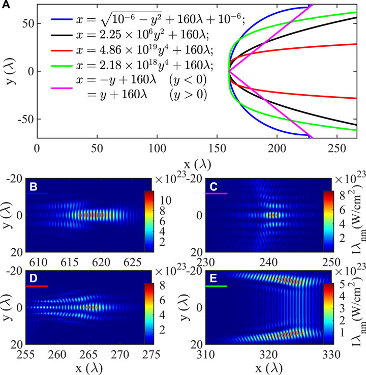
FIGURE 5. (A) The surface of concave structure obtained by different concave functions. (B–E) Pulse profiles snapshot of maximum intensity obtained by focusing the lenses of different concave structures correspond to (B) blue, (C) pink, (D) red, and (E) green lines in (A).
The plane plasma slab length L before the concave structure also affects the X-ray focusing process. In Figure 6, we show the effect of L on X-ray focusing for different L ranging from 50 to 350 nm, where the backside concave structure is fixed. Figure 6A shows the longitudinal distribution of X-ray pulses focused by concave plasma lenses of different L. With the increase of L, the pulse width becomes shorter and the pulse intensity also increases. However, laser plasma instability requires a certain development distance, and this distance is related to the input laser power, as shown in Figure 2. The plasma wave modulation, which appears first, at about 180λ for 6 TW and 80λ for 20 TW. The pulse broken occurs at 250λ for 6 TW and 110λ for 20 TW. When L is too long, the growth of instabilities destroys the pulse profile, as shown in Figure 2. In this case, Figures 6B, C show that the concave plasma lens can still locally focus the broken laser pulse, although the focused pulse becomes unstable compared with the case with shorter L. Thus, one should choose a relatively short L in experiments so that the LPI instabilities cannot grow seriously and the concave plasma lens can effectively focus the X-ray pulse.
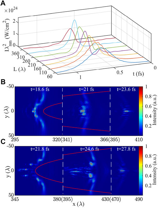
FIGURE 6. (A) Pulse time profiles after focusing by concave lenses with different L. (B) Focus pulse profiles at t = 18.6, 21 and 23.6 fs by concave plasma lens with L = 310λ. (C) Focus pulse profiles at t = 21.8, 24.6 and 27.8 fs by concave plasma lens with L = 360λ.
Because the X-ray wavelength is very short, the surface roughness of the concave plasma lens due to the limitations of the target manufacturing also needs to be considered. With the current advanced nanofabrication technology, many nanofabrication technologies can achieve fabrication precision of 10 nm scale [36], such as ion beam etching. In order to describe such effect, we randomly generate a number between 0 and R through the random function f(R) and apply it to the original concave function to simulate different degrees of roughness. The setting method is to cut the original surface into several sections in the transverse direction, and the length of each section is y′ − y = f(R), and approximate each section of the curve as a straight line, and set the slope as
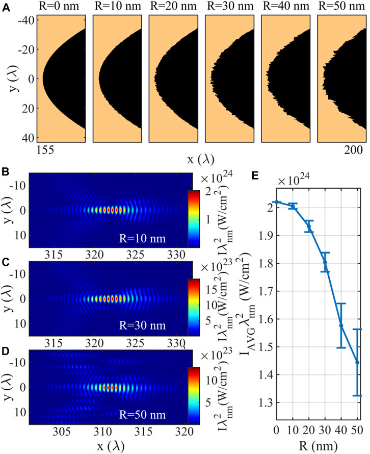
FIGURE 7. (A) Surface of concave structure with different roughness coefficients from 0 to 50 nm. (B–D) Focusing pulse intensity profiles obtained with roughness of (B) 10, (C) 30 and (D) 50 nm. (E) Simulation results of the average focusing intensity with different roughness coefficients, and the error bars represent the standard deviation.
Another factor is the offset of the pulse center from the center of concave structure, which must be considered in practical experiments. To address such effect, we simulate the laser misalignment by moving the position of the concave structure. The focused intensity decreases as the offset increases, as shown by the blue curve in Figure 8A. But it is noted that even the offset is about half the pulse radius, the focused pulse intensity is still higher than that for the plane plasma slab (shown as the red line in Figure 8A). Figures 8B, C show the offset pulse profile in the focusing process. In this case, the simulated incident pulse is centering on y = 0, and the transverse position of the concave structure is shifted by 500 nm. Figure 8B shows that when the pulse reaches the concave surface, it is asymmetrically focused toward the center of the concave surface. Finally, as shown in Figure 8C, the transverse position of pulse focus is located at y = 490 nm, which is close to the offset length or the center of the concave structure. This is very important for the experiment. It suggests that even when the incident position of the laser is offset from the concave plasma lens, the pulse can still be focused to the preset point through the concave plasma lens to interact with the target, which thus can greatly improve the operability of the experiment.
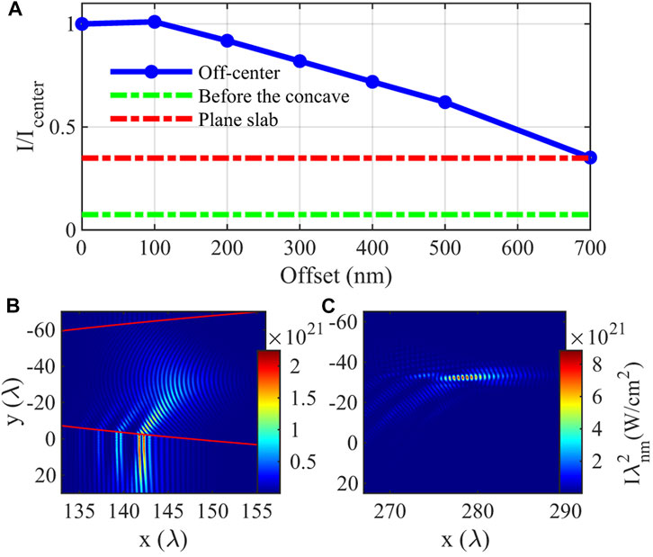
FIGURE 8. Simulation results of pulse center offset from concave center under 10 TW simulation. (A) The blue curve shows the change of focusing intensity as the offset increases. The green line is the intensity of the pulse before it interacts with the concave structure, and the red line is the intensity of the plane plasma slab. (B) and (C) The pulse profiles at t = 10 and 20 fs when the offset is 500 nm. The red curve is the concave surface.
Effects of QED on X-ray focusing
In the above section, we have demonstrated the efficiency and robustness of the concave plasma lens on X-ray focusing. In this section, we would discuss the QED effects during X-ray focusing. In our simulations, the QED effects are self-consistently included, and the QED parameter χ = γEL sin θ/Es is also calculated, where EL is electric field, θ is the angle between the electron momentum and EL, and Es = 1.3 × 10¹⁸ V/m is the Schwinger field. When χ is close to or equal to unity, the effect of QED becomes non-negligible. Under the cases of a plane plasma slab, Figure 9A shows that the QED effects have little effect on the focused laser intensity even for the laser power of 20 TW, where the oscillations shown in different simulation cases are caused by the LPI instabilities. In addition, we also calculate the value of χ. In our cases, EL can reach 2 × 10¹⁴ V/m, but γ is below 10, which results in a small value of χ. As shown in Figure 9B, χ remains on the order of 10–5 for Pin = 1 TW. For Pin = 20 TW, the value of χ is strongly perturbed and reaches a maximum of 4.8 × 10⁻⁴. The perturbation here is due to the combined action of EL and γ. After the pulse is broken, the pulse is locally self-focused and forms different filaments, thus resulting in the perturbation of laser electric field. Thus the EL perturbation is caused by the strong non-linear process of the filament pulse. On the other hand, the electrons are accelerated in the local wakefield stimulated by the filament pulse. Since the driving pulse is not stable, the wakefield is difficult to maintain and the acceleration phase is strongly disturbed, which thus result in the perturbation of γ.
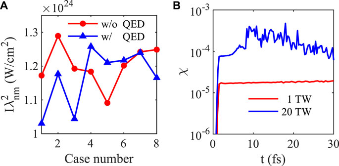
FIGURE 9. (A) Maximum intensity with and without QED block at Pin = 20 TW. (B) The maximum value of QED parameter χ at different simulation moments.
For the concave plasma lens, the effect of QED on the focusing intensity can be negligible because the concave plasma lens is very thin and the pulse intensity is very weak before leaving the plasma lens and entering the vacuum focusing. When the pulse enters a vacuum, the pulse no longer interacts with the electrons. The effect of QED on focusing intensity is thus negligible. In addition, the number of hard X-ray photons generated in solid-density plasmas is very small, so the influence of high-energy radiation generated by QED effect on the main pulse can be ignored. Therefore, the QED effect can be ignored when plasma lens is used for X-ray focusing.
Realization of concave structured plasma lens
In experiments, how to realize the solid-density plasma without damaging the concave structure is the key to achieve the concave plasma lens. Isochorically heating by ultrashort lasers, electron beams and X-rays in principle can produce homogeneous solid-density plasmas. In particular, recent research shown that infrared laser or frequency-doubling laser can isochorically heat and ionize copper to produce homogeneous micron-scale plasmas with well-characterized structures [32], which could be used for future experimental design to verify our scheme. To verify this point, we separate the same laser of 7 J, 45 fs and 400 nm into two beams with 50% energy each, corresponding I = 1.5 × 10²¹W/cm2. Such two pulses were used to heat a concave aluminum target (or carbon) target from two lateral directions, where the propagation direction is along the y axis and the irradiation center is at x = 4 μm in the simulation. Our simulation results show that both the carbon target and the aluminum target can achieve complete ionization and maintain a very well concave structure. As shown in Figure 10, the average electron density of the carbon target can reach 6.9 × 1023 cm−3, and that of the aluminum target can reach 7.8 × 1023 cm−3. In these cases, the concave structure behind the target can be well maintained. Although the plasma is slightly dented in the position of double frequency laser irradiation, it is far away from the concave structure, so it does not affect the focusing of the X-ray main pulse. In this case, the heated plasma temperature reaches several keV, which is consistent with the experimental results shown in Ref. [32]. Figure 10B shows the focal spot of an X-ray laser with the same parameters as in Figure 3 (Pin = 6 TW, τ0 = 0.5 fs, r0 = 1000 nm) that is incident on the ionized concave carbon target shown in Figure 10A. By comparing with the preset homogeneous plasma, where we obtain the focusing pulse profile at the same propagation distance, as shown in Figure 10C, and the intensity difference between the two cases is only about 3.9%. Therefore, the above two-laser approach can be used in experiments to produce the desired concave plasma lens for high-power X-ray focusing.
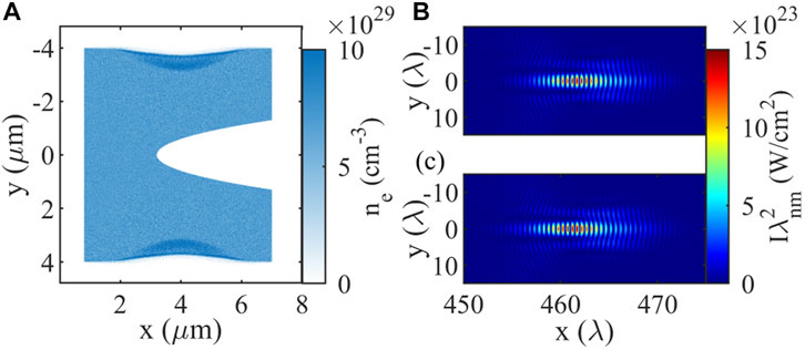
FIGURE 10. (A) Electron density distribution of a carbon target ionized from the side by two double-frequency laser. (B) X-ray pulse profile focused by an ionized carbon target of plane (A). (C) X-ray profile focused by a preset homogeneous plasma.
Electron acceleration driven by relativistic X-ray laser
The focused X-ray pulse can interact with a target attached behind the concave lens to produce brilliant particle and radiation sources with ultrashort duration. To verify this scheme, we simulate the interaction of relativistic intensity X-ray pulses and ultrathin solid films. In the simulations, a linearly polarized, 15 nm wavelength X-ray pulse is focused onto a plastic CH film located at x = 15λ. The focal spot radius of pulse is 10λ and the peak intensity is 1024 W/cm2, corresponding to α0 = 12.8. The plastic film is set as fully ionized hydrocarbon with an electron density of 4.2 × 1023 cm−3 and thickness of 10 nm. Such ultra-thin plastic target has been used in laser-driven proton acceleration experiment [37]. The simulation box is of size 125λ × 60λ in x × y space with 12,500 × 1,200 grids and 2,000 electron, 50 C6+ and 50 H+ per cell. The initial temperature of electrons is set to 10 keV.
When the relativistic X-ray laser interacts with the solid-density thin-foil, the latter would act as a thin layer of low-density plasma, and the former’s ponderomotive force would push the electrons out of the target and accelerates them in the strong laser fields. The spatial distributions of electron density and average kinetic energy are shown in Figures 11A, B. It shows that the electrons are distributed as nanoscale bunches and they are periodically spaced with half the X-ray wavelength. The duration of each electron bunch is about 15 as. Figure 11C shows that the nanoscale electron bunches are located around the node points of the transverse laser electric field, which is the typical characteristic of vacuum electron acceleration. The high-energy attosecond electron beam can be used to generate ultrashort radiation sources, which shall be discussed in the future work. Figure 11D for the electron energy spectrum shows that the accelerated electron bunch has a quasimonogenetic energy spectrum, which is peaked at about 18 MeV. This is mainly induced by the relatively small injection region of electrons in the thin-film. The peaked energy can be further increased during the propagation of X-ray in backside vacuum. The energy and density of the accelerating electron is related to the intensity of the driving X-ray. In Figure 11D, we also show the electron energy spectrum for different driving X-rays at different intensities. It is shown that with the increase of the driving pulse intensity, the electron energy and density can be significantly increased. When the initial intensity is 5 × 1024 W/cm2 (α0 = 28.65), the peak of electron energy is about 31 MeV. However, when the intensity of the driving pulse is lower than the relativistic intensity (α0 < 1), the attosecond pulsed electron beam cannot be generated. The physics of X-ray accelerated attosecond electron beam shall be discussed in detail in a future work.
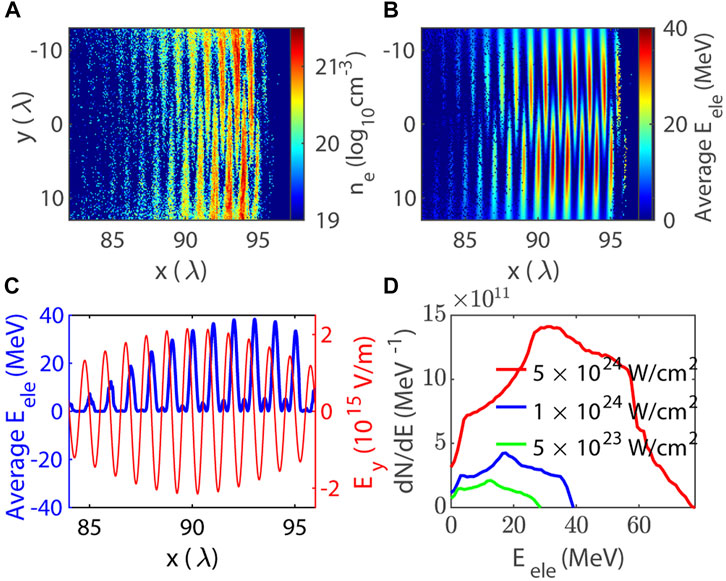
FIGURE 11. Electron acceleration by relativistic intensity X-ray pulse in vacuum. (A) Forward propagating electron density distribution. (B) Average kinetic of the electrons in (A). (C) The linear average kinetic energy of electron at y = 5λ ± 1λ (blue line, left axis), and electric field Ey at y = 5λ (red line, right axis). (D) The energy spectrum for the electron driven by different intensity X-rays.
Conclusion
In conclusion, we have systematically studied the focusing of high-power X-ray laser in solid-density plasmas. It is shown that within a certain wavelength range, solid-density plasmas can be used to focus X-ray pulses. However, focusing of X-ray laser at very high power is prevented by the laser-plasma interaction instabilities. To solve this problem, we further propose the employment of concave plasma lens, which can effectively avoid instabilities and realize X-ray focusing at very high-power levels. It is demonstrated that in such scheme terawatt-level X-ray pulses can be immensely focused while keeping high quality spatiotemporal profiles, leading to extremely intense X-ray laser of relativistic intensities. The parameters of the concave plasma lens are also discussed, which proves that the present scheme is quite efficient and robust. In addition, we show that when such focused X-ray laser is irradiated on a thin foil, high-quality attosecond/nanoscale electron bunches can be generated. The focused relativistic intensity X-ray pulses achieved here are expected to be widely used in strong field physics, high-energy density physics, quantum electrodynamics, laboratory astrophysics and other fields.
Data availability statement
The raw data supporting the conclusion of this article will be made available by the authors, without undue reservation.
Author contributions
TH designed and supervised the research. PC carried out the simulations, performed the calculations. PC, TH, and KJ analyzed the data. PC and TH wrote the manuscript. KJ, MY, and CZ commented on the manuscript. All authors have read and agreed to the published version of the manuscript.
Funding
This work is supported by the National Natural Science Foundation of China (Grants Nos 12175154, 11875092, and 12005149), the Natural Science Foundation of Top Talent of Shenzhen Technology University (Grant Nos 2019010801001 and 2019020801001). The EPOCH code is used under UK EPSRC contract (EP/G055165/1 and EP/G056803/1).
Conflict of interest
The authors declare that the research was conducted in the absence of any commercial or financial relationships that could be construed as a potential conflict of interest.
Publisher’s note
All claims expressed in this article are solely those of the authors and do not necessarily represent those of their affiliated organizations, or those of the publisher, the editors and the reviewers. Any product that may be evaluated in this article, or claim that may be made by its manufacturer, is not guaranteed or endorsed by the publisher.
References
1. Yoon JW, Kim YG, Choi IW, Sung JH, Lee HW, Lee SK, et al. Realization of laser intensity over 1023 W/cm2. Optica (2021) 8:630–5. doi:10.1364/OPTICA.420520
2. Tajima T. Laser acceleration in novel media. Eur Phys J Spec Top (2014) 223:1037–44. doi:10.1140/epjst/e2014-02154-6
3. Zhang X, Tajima T, Farinella D, Shin Y, Mourou G, Wheeler J, et al. Particle-in-cell simulation of x-ray wakefield acceleration and betatron radiation in nanotubes. Phys Rev Accel Beams (2016) 19:101004. doi:10.1103/PhysRevAccelBeams.19.101004
4. Shen B, Bu Z, Xu J, Xu T, Ji L, Li R, et al. Exploring vacuum birefringence based on a 100 pw laser and an x-ray free electron laser beam. Plasma Phys Control Fusion (2018) 60:044002. doi:10.1088/1361-6587/aaa7fb
5. Neutze R, Wouts R, Van der Spoel D, Weckert E, Hajdu J. Potential for biomolecular imaging with femtosecond x-ray pulses. Nature (2000) 406:752–7. doi:10.1038/35021099
6. Shapiro DA, Babin S, Celestre RS, Chao W, Conley RP, Denes P, et al. An ultrahigh-resolution soft x-ray microscope for quantitative analysis of chemically heterogeneous nanomaterials. Sci Adv (2020) 6:eabc4904. doi:10.1126/sciadv.abc4904
7. Kretschmar M, Hadjipittas A, Major B, Tümmler J, Will I, Nagy T, et al. Attosecond investigation of extreme-ultraviolet multi-photon multi-electron ionization. Optica (2022) 9:639–44. doi:10.1364/OPTICA.456596
8. Emma C, Fang K, Wu J, Pellegrini C. High efficiency, multiterawatt x-ray free electron lasers. Phys Rev Accel Beams (2016) 19:020705. doi:10.1103/PhysRevAccelBeams.19.020705
9. Tanaka T. Proposal for a pulse-compression scheme in x-ray free-electron lasers to generate a multiterawatt, attosecond x-ray pulse. Phys Rev Lett (2013) 110:084801. doi:10.1103/PhysRevLett.110.084801
10. Prat E, Reiche S. Simple method to generate terawatt-attosecond x-ray free-electron-laser pulses. Phys Rev Lett (2015) 114:244801. doi:10.1103/PhysRevLett.114.244801
11. Prat E, Löhl F, Reiche S. Efficient generation of short and high-power x-ray free-electron-laser pulses based on superradiance with a transversely tilted beam. Phys Rev ST Accel Beams (2015) 18:100701. doi:10.1103/PhysRevSTAB.18.100701
12. Heissler P, Horlein R, Mikhailova JM, Waldecker L, Tzallas P, Buck A, et al. Few-cycle driven relativistically oscillating plasma mirrors: A source of intense isolated attosecond pulses. Phys Rev Lett (2012) 108:235003. doi:10.1103/PhysRevLett.108.235003
13. Chen ZY, Li XY, Li BY, Chen M, Liu F. Isolated elliptically polarized attosecond soft x-ray with high-brilliance using polarization gating of harmonics from relativistic plasmas at oblique incidence. Opt Express (2018) 26:4572–80. doi:10.1364/oe.26.004572
14. Xu X, Zhang Y, Zhang H, Lu H, Zhou W, Zhou C, et al. Production of 100-tw single attosecond x-ray pulse. Optica (2020) 7:355–8. doi:10.1364/OPTICA.385147
15. Mimura H, Handa S, Kimura T, Yumoto H, Yamakawa D, Yokoyama H, et al. Breaking the 10 nm barrier in hard-x-ray focusing. Nat Phys (2010) 6:122–5. doi:10.1038/nphys1457
16. Chao W, Fischer P, Tyliszczak T, Rekawa S, Anderson E, Naulleau P. Real space soft x-ray imaging at 10 nm spatial resolution. Opt Express (2012) 20:9777–83. doi:10.1364/OE.20.009777
17. Yumoto H, Mimura H, Koyama T, Matsuyama S, Tono K, Togashi T, et al. Focusing of x-ray free-electron laser pulses with reflective optics. Nat Photon (2013) 7:43–7. doi:10.1038/nphoton.2012.306
18. Mimura H, Yumoto H, Matsuyama S, Koyama T, Tono K, Inubushi Y, et al. Generation of 1020 Wcm−2 hard x-ray laser pulses with two-stage reflective focusing system. Nat Commun (2014) 5:3539–5. doi:10.1038/ncomms4539
19. Pukhov A, Meyer-ter Vehn J. Relativistic magnetic self-channeling of light in near-critical plasma: Three-dimensional particle-in-cell simulation. Phys Rev Lett (1996) 76:3975–8. doi:10.1103/PhysRevLett.76.3975
20. Shou Y, Lu H, Hu R, Lin C, Wang H, Zhou M, et al. Near-diffraction-limited laser focusing with a near-critical density plasma lens. Opt Lett (2016) 41:139–42. doi:10.1364/OL.41.000139
21. Chen ZY, Pukhov A. Plasma-based polarization modulator for high-intensity lasers. Phys Plasmas (2016) 23:123107. doi:10.1063/1.4971232
22. Turnbull D, Michel P, Chapman T, Tubman E, Pollock BB, Chen CY, et al. High power dynamic polarization control using plasma photonics. Phys Rev Lett (2016) 116:205001. doi:10.1103/PhysRevLett.116.205001
23. Trines R, Fiuza F, Bingham R, Fonseca R, Silva L, Cairns R, et al. Simulations of efficient Raman amplification into the multipetawatt regime. Nat Phys (2011) 7:87–92. doi:10.1038/nphys1793
24. Peng H, Marquès J-R, Lancia L, Amiranoff F, Berger R, Weber S, et al. Plasma optics in the context of high intensity lasers. Matter Radiat Extremes (2019) 4:065401. doi:10.1063/1.5091550
25. Thaury C, Quere F, Geindre J-P, Levy A, Ceccotti T, Monot P, et al. Plasma mirrors for ultrahigh-intensity optics. Nat Phys (2007) 3:424–9. doi:10.1038/nphys595
26. Chen M, Luo J, Li F-Y, Liu F, Sheng Z-M, Zhang J. Tunable synchrotron-like radiation from centimeter scale plasma channels. Light Sci Appl (2016) 5:e16015. doi:10.1038/lsa.2016.15
27. Luo J, Chen M, Wu W, Weng S, Sheng Z, Schroeder C, et al. Multistage coupling of laser-wakefield accelerators with curved plasma channels. Phys Rev Lett (2018) 120:154801. doi:10.1103/PhysRevLett.120.154801
28. Yu L-L, Zhao Y, Qian L-J, Chen M, Weng S-M, Sheng Z-M, et al. Plasma optical modulators for intense lasers. Nat Commun (2016) 7:11893–7. doi:10.1038/ncomms11893
29. Nie Z, Pai C-H, Hua J, Zhang C, Wu Y, Wan Y, et al. Relativistic single-cycle tunable infrared pulses generated from a tailored plasma density structure. Nat Photon (2018) 12:489–94. doi:10.1038/s41566-018-0190-8
30. Habara H, Lad AD, Nagami R, Singh PK, Chatterjee G, Adak A, et al. Micro-optics for ultra-intense lasers. AIP Adv (2021) 11:035214. doi:10.1063/5.0038023
31. Bostedt C, Boutet S, Fritz DM, Huang Z, Lee HJ, Lemke HT, et al. Linac coherent light source: The first five years. Rev Mod Phys (2016) 88:015007. doi:10.1103/RevModPhys.88.015007
32. Beier NF, Allison H, Efthimion P, Flippo KA, Gao L, Hansen SB, et al. Homogeneous, micron-scale high-energy-density matter generated by relativistic laser-solid interactions. Phys Rev Lett (2022) 129:135001. doi:10.1103/PhysRevLett.129.135001
33. Patel P, Mackinnon A, Key M, Cowan T, Foord M, Allen M, et al. Isochoric heating of solid-density matter with an ultrafast proton beam. Phys Rev Lett (2003) 91:125004. doi:10.1103/PhysRevLett.91.125004
34. Sun G, Ott E, Lee Y, Guzdar P. Self-focusing of short intense pulses in plasmas. Phys Fluids (1987) 30:526–32. doi:10.1063/1.866349
35. Arber T, Bennett K, Brady C, Lawrence-Douglas A, Ramsay M, Sircombe N, et al. Contemporary particle-in-cell approach to laser-plasma modelling. Plasma Phys Controlled Fusion (2015) 57:113001. doi:10.1088/0741-3335/57/11/113001/meta
36. Liu Z, Liu N, Schroers J. Nanofabrication through molding. Prog Mater Sci (2022) 125:100891. doi:10.1016/j.pmatsci.2021.100891
Keywords: X-ray laser, self-focusing, solid density plasma, structured target, relativistic intensity
Citation: Chen P, Huang T, Jiang K, Yu M and Zhou C (2022) Achieving relativistically intense X-rays from structured plasma lens. Front. Phys. 10:1085045. doi: 10.3389/fphy.2022.1085045
Received: 31 October 2022; Accepted: 05 December 2022;
Published: 14 December 2022.
Edited by:
Guo-Bo Zhang, National University of Defense Technology, ChinaReviewed by:
Amit Lad, Tata Institute of Fundamental Research, IndiaTakeshi Higashiguchi, Utsunomiya University, Japan
Copyright © 2022 Chen, Huang, Jiang, Yu and Zhou. This is an open-access article distributed under the terms of the Creative Commons Attribution License (CC BY). The use, distribution or reproduction in other forums is permitted, provided the original author(s) and the copyright owner(s) are credited and that the original publication in this journal is cited, in accordance with accepted academic practice. No use, distribution or reproduction is permitted which does not comply with these terms.
*Correspondence: Taiwu Huang, taiwu.huang@sztu.edu.cn