Unified power quality conditioner-based solar EV charging station using the GBDT–JS technique
 Ch. S. V. Prasada Rao1 A. Pandian1
  Ch. Rami Reddy2,3
  Mohit Bajaj4,5,6,3
  Jabir Massoud7*
  Mokhtar Shouran8
- 1Department of Electrical and Electronics Engineering, Koneru Lakshmaiah Education Foundation, Guntur, India
- 2Department Electrical and Electronics Engineering, Joginpally B. R. Engineering College, Hyderabad, India
- 3Applied Science Research Center, Applied Science Private University, Amman, Jordan
- 4Department of Electrical Engineering, Graphic Era (Deemed to be University), Dehradun, India
- 5Hourani Center for Applied Scientific Research, Al-Ahliyya Amman University, Amman, Jordan
- 6Department of Electrical Engineering, Graphic Era Hill University, Dehradun, India
- 7School of Engineering, Cardiff University, Cardiff, United Kingdom
- 8Libyan Center for Engineering Research and Information Technology, Bani Walid, Libya
This manuscript proposes a novel hybrid artificial intelligence (AI) approach for a unified power quality conditioner (UPQC) designed specifically for electric vehicle charging stations (EVCSs). The aim is to integrate multiple vehicle-to-grid (V2G) functionalities, thereby mitigating the challenges associated with electric vehicle (EV) grid integration and the incorporation of distributed energy resources (DERs). The hybrid technique presented in this manuscript combines the gradient boosting decision tree (GBDT) algorithm and the jellyfish search (JS) algorithm, referred to as the GBDT–JS technique. This innovative approach involves utilizing the charging station to offer EV charging services and facilitating the discharge of EVs to the power grid. Integration of the UPQC with DERs, such as photovoltaic (PV), is implemented to decrease the power rating of converters and fulfill power demand requirements. The initial converter within the UPQC is employed to manage the direct current (DC) voltage, while the second converter oversees the power charging or discharging processes of EVs. Additionally, it mitigates the impact of battery voltage fluctuations. The UPQC with vehicle-to-grid functionality minimizes the load pressure on the grid, preventing over-current issues. The presented approach regulates the UPQC converters to mitigate power quality issues such as harmonic currents and voltage sags. Subsequently, the effectiveness of this technique is demonstrated using the MATLAB/Simulink operating platform. The evaluation of GBDT–JS performance involves a comparative analysis with existing techniques. This assessment reveals that the proposed method effectively alleviates power quality issues, specifically reducing total harmonic distortion (THD), and delivers optimal outcomes.
1 Introduction
With the development of electric vehicles (EVs), a marvelous impulse in the automotive industry occurred to minimize the high consumption of greenhouse gases and fossil fuel resources (Cardoso et al., 2014). Electric vehicle charging stations (EVCSs) have gained prominence as the predominant infrastructure, particularly in urban areas (Rezaee et al., 2013). EVs serve as distributed energy resources (DERs), and their accessibility plays a crucial role in influencing investments in DERs and the strategic planning of the power supply network (Pang et al., 2012; Huang et al., 2021; Ravindran et al., 2023). The fundamental challenges are obtaining more service power grids from electric vehicle charging stations (Liu et al., 2013a) and maximizing the benefits derived from EVCSs for the power grids (Crosier and Wang, 2013). These EVCSs are utilized as power filters in bandwidth regulation, load shifting, generation balance, and STATCOM (Wang and Wang, 2013; Liu and Liu, 2021a; Kumar et al., 2023). In their work, S. Devassy and B. Singh (Devassy and Singh, 2018; Liu and Liu, 2021b; Oubelaid et al., 2022a) devised an integrated approach incorporating a unified power quality conditioner (UPQC) with a three-phase solar PV system. The study involved an analysis of dynamic performance under varying irradiation levels and instances of grid voltage sags or swells. Notably, their investigation did not take into account the impact of current harmonics and reactive power compensations. In their research, R.H. Yang and J.X. Jin (Yang and Jin, 2021; Kakouche et al., 2022; Sun et al., 2022) employed a cost-effective energy storage device integrated into the UPQC for a protective strategy. This scheme involved utilizing both a series-side converter and a parallel-side converter to mitigate power oscillations. However, their study did not take into account the influence of balanced grid current and voltage harmonics.
When grids are attached to EVs, the local distribution network faces disturbances from charging devices like power quality (PQ) factors in voltage fluctuations, voltage imbalances, and harmonics (Jargstorf and Wickert, 2013). The integration of EVs with the grid introduces challenges to power quality parameters, such as voltage imbalances, fluctuations, and harmonics, impacting the local distribution network (Liu et al., 2013b; Sun et al., 2019; Hamed et al., 2023). Numerous studies have been dedicated to addressing and mitigating the adverse effects of EV chargers on power quality (Jian et al., 2014). Active power filters (APFs) are chosen because of their fast and more powerful compensation abilities, which are used to overcome the problems of PQ (Di Giorgio et al., 2014; Li et al., 2022a; Hamed et al., 2022). Generally, the voltage harmonics and supply voltage disturbances are reduced by the series inverter (Leemput et al., 2015). Parallel-connected inverters play a role in alleviating issues related to current distortions, current harmonics, and reactive power loads, as evidenced by Tanaka et al. (2013); Karthikeyan et al. (2022); Lin et al. (2022). The reduction of both present and voltage-based distortions is achieved through the utilization of a UPQC, which incorporates series and parallel APFs along with a shared direct current (DC) link (Xia and Li, 2013). Hence, it improves the quality of power. Due to the restricted cost and complex control of the UPQC, its utilization is limited in local distribution networks (Oubelaid et al., 2022a). In their studies, Yan and Wen (2021); Gao et al. (2022); Yang et al. (2022) introduced the DC-UPQC approach, incorporating a series-side distribution static synchronous compensator (DAB), a parallel-side DAB, and a superconducting magnetic energy storage (SMES) system. Their analysis focused on addressing DC voltage oscillations arising from AC-side asymmetrical faults. However, the study did not emphasize power factor correction (PFC) capacity or compensation for reactive power. In their work, S. Devassy and B. Singh (Devassy and Singh, 2017; Ding et al., 2023) introduced a p–q theory centered on the integration of solar photovoltaic with a UPQC. This approach not only involves clean energy generation but also enhances power quality, thereby augmenting the overall system functionality. However, the study does not take into account the impact of voltage and current harmonics.
EVCSs support UPQCs for local power supply networks, which engage in higher revenue investments and improve power quality (Pal et al., 2012). To interconnect renewable power generation systems, it is essential to sustain the quality of the source voltage within the specified tolerance band to prevent faults during grid-mode operations (Bai et al., 2015; Kraiem et al., 2021; Zhang et al., 2021). The UPQC plays a crucial role in preserving the source voltage quality when faults occur in renewable energy systems, such as photovoltaic (PV) and wind (Millnitz dos Santos et al., 2014). The vehicle-to-grid (V2G) mode of operation is a focal point in distributed systems (Karanki et al., 2013; Mohamed et al., 2021; Dharavat et al., 2022). The charging and discharging of an energy storage device (ESD) is utilized in a UPQC to stabilize the direct current voltage for the series and parallel APFs (Hegazy et al., 2013). One of the challenges arises from the infrequent charging/discharging of EVs, taking into account the owners' battery lifespan and preferences (Lee and Moon, 2014; Aymen et al., 2021; Shen et al., 2023). Another issue stems from the diverse voltage levels found in EV batteries at a single station due to different battery types and charging states, making direct connection to direct current impractical. As a result, the adoption of converters emerges as an effective solution for EV charging (Moreno et al., 2008). In their publication, Ye et al. (2018) and Yang et al. (2023) explored a phase angle control technique detailing the adjustment of displacement angles to modify the online VA loading. They presented a two-stage algorithm designed to optimize the selection of shunt and series converters, aiming to minimize their ratings while maximizing the overall ratings of the UPQC. Notably, the study did not delve into the impact of voltage harmonics and PFC capabilities. In their research, Meng et al. (2022) and Jiang and Xu (2023) introduced a control strategy tailored for a single-phase UPQC with the aim of mitigating the impact of grid current harmonics. The series converter in their approach incorporates DC-link voltage feedback to mitigate the influence of voltage ripple. However, the studies do not address the effects of SMES or power compensation.
The main contributions of this work are listed as follows:
• Implementation of an advanced solar charging station with power quality improvement features using the gradient boosting decision tree (GBDT)–jellyfish search (JS) technique.
• Developing an easy implementation method using the MDSOGI-MPC technique for synchronization of the grid and solar PV system.
• Developing a fast and precious load estimator in dynamic conditions for optimal performance of voltage source converters (VSCs).
• The regulation of active power and reactive power is activated based on the system’s needs, such as ride-through operation or point of common coupling (PCC) voltage assistance. The subsequent control state involves determining the cost minimization function.
The presented manuscript introduces a hybrid approach for UPQC-based EVCSs, aiming to amalgamate multiple V2G functions and mitigate the effects of EV grid integration and DERs. This hybrid technique incorporates the GBDT algorithm and jellyfish search (JS), collectively referred to as the GBDT–JS technique.
2 Recent research works: a brief review
Several research studies documented in the existing literature explored UPQC-based VSCs in conjunction with distributed energy resources, employing diverse methods and characteristics. Some of these studies are highlighted as follows: D. Jaraniya and S. Kumar (Jaraniya and Kumar, 2021; Bai et al., 2022; Jiang and Xu, 2024) developed a zero-attractor joint optimization-based normalized least mean square (ZAJO-NLMS) technique to enhance PQ. The various parallel PV array VSCs were incorporated with CS. The central PV system was linked to the grid via the VSC and a battery storage bank, while the remaining PV systems were allocated for secondary purposes. The developed approach aimed to analyze V2G scenarios with and without photovoltaic sources, encompassing renewable generation from grid-to-vehicle (G2V) and the grid-interactive mode with nonlinear load dynamics. A bidirectional converter was employed to regulate the voltage of the direct current bus. The proportional–integral (PI) controller was utilized to manage the voltage. The introduced approach extracted the fundamental load current and was utilized to control the CS. In their work, Jin et al. (2022) introduced an electric vehicle charging station incorporating a UPQC and an SMES system. Their system aims to regulate the power quality on both the grid and load sides, addressing challenges arising from the integration of EVs into the grid. Notably, the study does not account for the impact of PFC capability.
M Rekik and L Krichen (Rekik and Krichen, 2021; Wang et al., 2021; Shirkhani et al., 2023) developed the grid frequency control method for power flow control for PVs to the grid. The implemented system integrated PV and plug-in electric vehicle (PEV) components to oversee active power management and offset nonlinear load currents. The devised strategy comprised two modules: a neuronal nonlinear (NL) load current identification system and a grid frequency control algorithm. The initial unit was employed to identify the harmonic component of the line current and adjust the references for PVs and PEV converters. The power flow control between PVs and the electrical network was obtained using the second unit. Kar et al. (2021) introduced a time-domain optimization method aimed at diminishing harmonics in the output voltage and current waveforms when dealing with RL load. The optimization constraints taken into account included the total harmonic distortion of both current and voltage. The study also involved an examination of the impact of variations in load parameters on the harmonic content of load current and voltage. Routray et al. (2019) introduced a modified particle swarm optimization (MPSO) designed to minimize harmonics in a three-phase, eleven-level hybrid cascaded multilevel inverter (HC-MLI). The HC-MLI was analyzed to determine optimal switching angles aimed at eliminating odd harmonics from the output voltage.
SMES stands out among the proposed technologies for daily energy storage in electric utilities due to its distinctive feature: it avoids converting stored electrical energy into another form like mechanical, thermal, or chemical energy. Instead, the electrical energy is directly stored as a circulating current within a sizable superconducting magnet. SMES represents a straightforward approach to storing electrical energy, leveraging the dual nature of electromagnetism. Consequently, one of the advantages of SMES lies in its inherent high storage efficiency, as it circumvents the energy conversion processes. The anticipated round-trip efficiency of a substantial unit is projected to be 90 percent or higher. Zhong et al. (2016a), Mohanty et al. (2022), and Wang et al. (2022) explained that the topology of UPQCs uses a microgrid (MG) in an EVCS. Within the MG, EVs were interconnected in parallel using a dual-layer direct current structure, which was strategically implemented to mitigate voltage fluctuations in the unified power quality conditioner. The management of an appropriate power quality conditioner addresses the challenges associated with EV charging by allowing direct electricity supply from the grid and is employed to rectify power quality issues. To counteract power interruptions during sudden power distribution, discharge control was applied in a time-proportional manner to the electric vehicles, while the CS UPQC was in operation. When guaranteeing the charging of EVs, the introduced system minimized power quality issues. P. Kumar Kar (Kumar Kar et al., 2019; Oubelaid et al., 2022b) innovated a switching technique based on the whale optimization algorithm (WOA), requiring a reduced number of power semiconductor devices, thus enhancing its cost-effectiveness for various applications. This WOA-based switching method delivers improved inverter response within a shorter computational time, demonstrating heightened efficiency and superior performance. Srndovic et al. (2016) introduced a novel optimization approach utilizing staircase modulation to minimize the total harmonic distortion (THD) in voltage and current for a single-phase multilevel inverter. This method facilitates the computation of optimal switching angles, considering all switching harmonics, which differs from prior research that primarily focused on frequency domain analysis with a restricted range of harmonic numbers.
Vinothkumar and Kanimozhi (Li et al., 2022b; Vinothkumar and Kanimozhi, 2022; Duan et al., 2023) developed the predictive phase dispersion modulation (PPDM) technique for compensating the current harmonics on the load side and the voltage sag or expansion on the source side because of loads. Roberge et al. (2015) employed a parallel computing approach to determine the optimal switching angles for harmonic minimization in multilevel inverters. The study focuses on uneven DC voltage sources and utilizes graphics processing units (GPUs). The research explores how minimal THD values and switching angles vary with changes in inverter level count and modularity. Sharifzadeh et al. (2019) introduced an adapted form of selective harmonic mitigation pulse amplitude modulation (SHM-PAM) capable of neutralizing all triplen harmonic orders. This modification is particularly suitable for single-phase applications using five-level voltage source inverters. The unified power quality conditioner was connected to the developed system, and the shunt and series converters of the suitable power quality conditioner were controlled by the developed approach. The conventional DC link capacitor was linked between the series and shunt converters. The key innovation of the proposed approach lies in maintaining a constant DC link voltage and regulating the switching pulse control of the cascaded H-bridge multilevel inverter (CHBMLI) based on variations in current on the load side. Additionally, the method effectively handles the unbalanced voltage on the source side. The developed method analyzes issues like sag, swell based on power electronics, and various nonlinear loads.
Roberge et al. (2014) put forward a method for determining the optimal switching angles in multilevel inverters with diverse DC sources. They recommend a parallel implementation of the genetic algorithm (GA) using a GPU. Diong et al. (2013) devised an approach to reduce THD or frequency-weighted THD (WTHD) in the output voltage of single-phase multilevel inverters. The modulation involves the use of a staircase, with the option to either eliminate the lowest-order harmonics or retain them. Sarita et al. (2020), Balan et al. (2022), and Afzal et al. (2023) suggested the fuzzy logic controller (FLC) and artificial neural network (ANN) for hybrid system power enhancement. The devised approach was integrated with both solar PV and wind energy (PV-WE), coupled with energy storage systems (ESSs) and EVs. This proposed method accounts for bidirectional power flow involving V2G and G2V facilitated through an electric vehicle aggregator (EVA). The source-to-load power flow is regulated by an FLC, ensuring the maintenance of power quality on the load side through the application of a UPQC. The ANN approach tracked maximum power. Gowri Shankar and M. Ramasamy (Gowrishankar and Ramasamy, 2019; Panchanathan et al., 2023; Zhang et al., 2023) developed the modified power angle control (PAC) method for UPQC-connected renewable energy systems. The main objective of the devised approach is to alleviate the voltage–ampere (VA) load on the shunt (APF) through the utilization of reactive power. The integration of PVs with UPQCs and the application of the synchronous reference frame (SRF) by the developed method aim to enhance the quality of management. The analysis of the developed method shows the performance of PV-UPQC based on grid disturbances like voltage sag, varying load, swell, and solar irradiation change. S S et al. (2021a), Venkatesan et al. (2022), and Shanmugam et al. (2023) suggested reinforced learning algorithms for solar-integrated UPQCs. The recommended approach involved the simultaneous implementation of reactive power control and a unit vector template. The main objective of this proposed method was to meet the load demands while concurrently minimizing the power rating of the converters. The nonlinear load-caused distortion was eliminated using the recommended method.
Recent research shows that power quality is a remarkable contributing factor. The utility grid is one of the PQ problems because of the electronic devices’ power and the combination of DERs. Some PQ issues are flickers, voltage dips, and supply and harmonic interruptions. When PQ is less, some losses occur. Integrating EVs with distributed renewable resources holds paramount significance. EVs play a crucial role in controlling frequency, reactive power, and active power, serving three operational modes: vehicle-to-building (V2B), vehicle-to-grid (V2G), and vehicle-to-home (V2H). Further research is necessary to explore the integration of various electric vehicles into the structure of EVCSs for the development of UPQCs. This UPQC, coupled with an ESS, addresses output fluctuations in compensating renewable energy, regulates power flow, and enhances generation reserve, voltage profile, and PQ. The battery life is impacted by the simultaneous functions of V2G, involving multiple charging/discharging cycles. The integration of numerous EVs with a UPQC is imperative for the topology of EVCSs. The incorporation of multiple V2G functions adds complexity and may lead to PQ issues. Therefore, power quality is sustained through the application of various filtering techniques and compensators, even when facing load variations under static and faulty conditions. The utility grid PQ at the distribution side is improved using the UPQC, a FACTS device. PQ is improved by compensating for reactive and real power using the UPQC. Although the EVCS has been incorporated into the UPQC-based DERs, there is a scarcity of studies addressing this integration. Connecting UPQC-DG with EVs gives rise to significant fluctuations in the DC side voltage. To address voltage fluctuations and enhance power quality, various methodologies have been proposed, including FLC and ANNs. FLC requires a substantial amount of data and becomes impractical for scenarios with data counts significantly lesser or greater than historical data. Particle swarm optimization and genetic algorithms, while effective, are hindered by their slow optimization process and the inability to promptly identify the optimal solution. Additionally, an ANN demands extensive data for its operations, prompting the need for this research to overcome these drawbacks.
3 Configuration of an EVCS-based UPQC based on the proposed approach
The management of EV charging is employed to mitigate the impacts of EV-to-grid connections, but it does not address issues related to harmonics. To capitalize on the benefits of SMES, such as high efficiency, extended service life, and elevated power density, this paper incorporates SMES to alleviate the effects of integrating EVs into the grid. The connection of EVs to the grid involves the use of converters, and the increasing use of converters contributes to the generation of harmonics, consequently diminishing power quality (Zhong et al., 2016b; Zhong et al., 2016c; Campanhol et al., 2019). The present paper introduces the hybrid GBDT–JS technique as a solution to power quality challenges. In this approach, a V2G-based UPQC is taken into account to alleviate voltage current loading, and during sag conditions, active power is transmitted to the grid through the V2G mode. The operation of EVCSs is synchronized with the UPQC, followed by the coupling of PV and SMES to the DC modular sub-grid. Under voltage-sag conditions, the proposed technique enhances grid fault protection and diminishes VA loading on the UPQC. The overall structure of UPQC-based EVCSs is displayed in Figure 1.
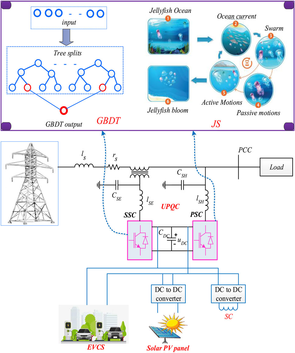
Figure 1. Structure of the UPQC-based EVCS.
The system includes a series-side converter (SSC), a DC-side capacitor, a parallel-side converter (PSC), an EVCS, an SMES, and a PV module. The PV module is connected to the DC bus using a boost converter. Various loads, encompassing both nonlinear and linear loads, are integrated into the system.
3.1 Modeling of solar photovoltaic
Solar photovoltaic (SPV) panels harness solar energy to generate power. Within the SPV panel (Khorasani et al., 2017), a portion of solar energy is transformed into electricity, while the remaining amount is converted into heat. Consequently, the power output of the SPV panel is contingent on both the temperature and solar radiation. The SPV panel output power is expressed in Eq. 1 as follows:
Here, solar radiation is denoted as
Here,
Here,
Here,
The structures of (a) PV with a boost converter and (b) photovoltaic control are depicted in Figure 2. The maximum power is obtained using a boost converter. Here, the control of DC voltage is not corrected. Only the highest operating point of PV is considered.
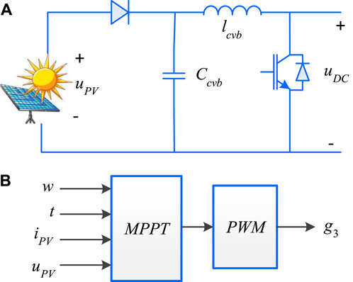
Figure 2. Structure of (A) PV with a boost converter and (B) photovoltaic control.
3.2 Charging and discharging control of EVs
The DC modular sub-grid is established through the parallel connection of the EVCS, PV, and SMES to the DC bus. The PV, facilitated by a boost converter, is linked to the DC bus, while SMES is integrated with superconductivity coils (SC) and a DC chopper (Al Balushi, 2020; S S et al., 2021b; Amini and Jalilian, 2021). The system incorporates five charging stations connected to the EVCS, which are designed to efficiently charge EV batteries. A battery management system (BMS) is responsible for detecting the state of charge (SOC) of the EVs and orchestrating changes in the power operating mode by compensating for the SOC.
3.2.1 DC charging piles
The structure of the charging pile is displayed in Figure 3. Using the buck/boost circuit, the charging bank is modeled. By controlling the on and off states of
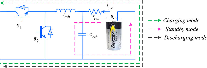
Figure 3. Structure of the charging pile.
Here, the power
The charging and discharging control of EVs is displayed in Figure 4. EV charging is standard, but discharging is based on the SOC at the V2G mode of operation. Charging of the EV battery is described using Eq. 8 as follows:
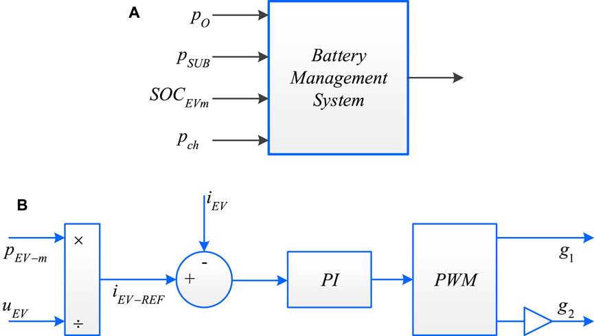
Figure 4. Electric vehicle (A) Battery management system, (B) Charging and discharging controller.
Here, rated charging power is represented as
Here, the EV SOC is denoted as
3.3 Superconducting magnetic energy storage
The safe operation of EV batteries is essential, but PSC operation does not provide stable operation when the grid fluctuates or faults occur. The SMES is linked in parallel with the distribution lines using a converter. This converter, adopting a voltage source converter type with a DC chopper, plays a crucial role in the system. Control of the system is facilitated by three regulators, each dedicated to managing specific aspects: the DC-link voltage, power exchange with the SMES, and the AC-currents within the inverter. The regulators overseeing power flow and AC-currents operate in a cascaded manner, while the DC-link voltage controller operates independently, ensuring that the voltage remains constant with the assistance of the SMES (Patel et al., 2020). SMES is utilized to transfer energy with high power density. Using the modes of operation, it controls DC-link voltage. The SMES and its percentage are presented in Eqs 10, 11, respectively, which are as follows:
Here, the equivalent inductance, actual and rated capacity of SMES are denoted as
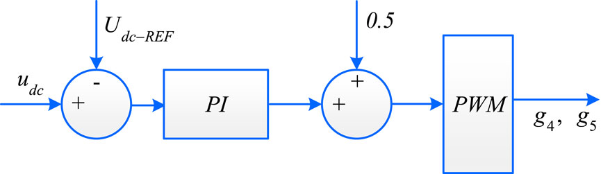
Figure 5. Control of SMES.
4 Principle and control of the UPQC
The UPQC is integrated into both the PSC and SSC and linked through a DC-side capacitor. The SSC is connected to the grid via three coupling transformers. The introduction of compensating voltage on the grid side effectively resolves power quality issues. Addressing the load-side concerns involves connecting the PSC in parallel to the PCC and generating compensating current to mitigate the load-side problems. An LC filter is appended to both side converters. The collaboration of both SSC and PSC collectively manages the power quality issues for both the load and grid sides.
4.1 Control of the series-side converter
The proposed methodology involves a three-phase system and does not account for the zero-sequence component. Figure 6 illustrates the control of the SSC based on the suggested approach. The proportional–integral (PI) controller (Mansor et al., 2020) receives the error between the actual and reference load voltages. The proposed technique optimally tunes the PI controller, and the output is subjected to dq to abc transformation. Subsequently, the compensated voltage is generated and fed into the pulse width modulation (PWM) generator. This PWM generator produces signals for the switching of the SSC, effectively controlling the system voltage.
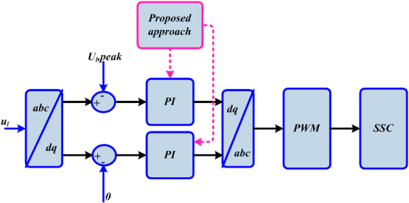
Figure 6. Control of a SSC based on the proposed approach.
The active and reactive power of the grid and SSC are expressed using Eqs 12, 13 as follows:
Here, the total active power of the grid is denoted as
4.2 Control of the parallel-side converter
The control strategy for the PSC in accordance with the proposed technique is depicted in Figure 7. The PSC control mechanism is designed to detect load current harmonics. Utilizing the proposed method, the compensated current (Leon et al., 2011) is generated. This equalized signal is then directed to the hysteresis current controller to generate the switching signal.
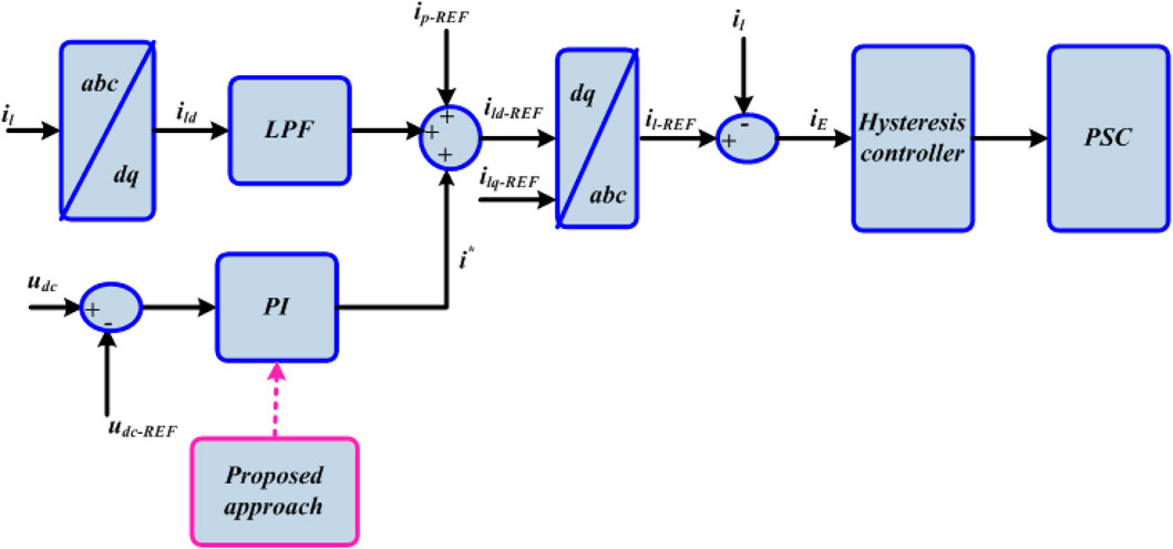
Figure 7. Control of a PSC based on the proposed approach.
Using the Parks transform, the dq component of load current is obtained. The LPF is utilized to attenuate the harmonic element of AC. If the supercapacitor controls the DC voltage, then power transfer to the grid is achieved by PSC control. Based on the grid voltage, the reference current is described using Eq. 14 as follows:
Here, the power of the DC sub-grid is denoted as
The reference load current is achieved by Eq. 17, which is as follows:
The active and reactive power of the grid and PSC are described using Eqs 18 and 19 as follows:
Here,
Through the grid and PSC, all active and reactive powers of load are obtained.
5 Proposed GBDT–jellyfish approach for PQ improvement in UPQC-based EVCS
To enhance the power quality of the EVCS system based on the UPQC, the GBDT–JS technique is introduced. Through the UPQC converter control, the power quality is improved, and the constant maintenance of the DC-link voltage is ensured. The system incorporates SMES to store energy efficiently. The utilization of the V2G function is considered to minimize the grid load. A detailed explanation of the proposed technique is provided below.
5.1 Generation of control signals based on the jellyfish search approach
The meta-heuristic approach employed in this research, known as JS, draws inspiration from the characteristics of jellyfish in the ocean. Consequently, it is termed the artificial jellyfish search optimizer. This approach incorporates features such as the passive and active motion of a jellyfish swarm, ocean currents, switching movements, and jellyfish convergence (Chou and Truong, 2021). The formulation of the jellyfish search approach is guided by three rules, wherein it follows movements within the swarm. Similar to how jellyfish move in the ocean in search of food, it adheres to a time-order control, encompassing switching movements. The JS is attracted to locations abundant in food resources. This manuscript demonstrates the utilization of jellyfish search to generate system control signals for regulating current and voltage, as well as for reference generation. The stepwise procedure of JS is elucidated as follows:
Step 1: Initialize the parameters
Initializing the system input parameters. The initial location of jellyfish search includes the control vector, state vector, and disturbance vector for the systems. The parameters, such as DC voltage and power demand, and PI parameters, such as
Step 2: Randomly generate parameters
After the initialization process, input parameters are generated randomly. Here, the highest fitness values are chosen within the jellyfish swarm depending on the location of food and the fitness role. The randomly generated parameters are described using Eq. 21 as follows:
Here, the gain parameter is denoted as
Step 3: Fitness function calculation
The fitness function depends on the objective function. Thus, fitness functions are generated using Eq. 22 as follows:
Step 4: Control time calculation
Its value is random, which varies from 0 to 1 over time and provides c(t) as the control function. c0 represents the constant. The time control functions are shown in Eq. 23 as follows:
where
Step 5: Update the parameters
Update all parameters based on the movement of jellyfish in the ocean, as they move within a jellyfish swarm.
Step 5.1: Jellyfish follow the ocean current
If control times are equal to or greater than 0.5, then the jellyfish follow the ocean current. Hence, this ocean current is explained using Eq. 24 as follows:
Here,
Step 5.2: Jellyfish move inside the jellyfish swarm
The jellyfish move in the swarm if the control time is reduced below 0.5. Therefore, it can be denoted using Eq. 26 as follows:
The lower and upper side bounds for search space are represented as
Then, the location is updated, and it is represented using Eq. 28 as follows:
Step 6: Checking the boundary and stopping the condition
When the parameter meets the boundary condition and criteria for stopping, it determines its optimal control signal; otherwise, it returns to step 3.
5.2 Prediction of the control signal by GBDT
GBDT enables the optimization of functions and provides values for optimized data. The GBDT strategy employs a prediction model to categorize the invalid parameters within the decision tree. Similar to other methods, it iteratively builds and refines step-wise decisions, facilitating the optimization of any loss function. The primary objective of the GBDT algorithm is to construct a set of weak base classifiers into robust classifiers (Kannan et al., 2022). This research establishes global convergence for systems. The stepwise procedure for GBDT is elucidated as follows:
Step 1: Initialization of the parameters
The input vectors are initialized from the output of the JS approach. Then, the initialized parameters are described using Eq. 29 as follows:
where
Step 2: Calculate the objective function
The objective function is computed by evaluating the power demand using Eq. 30. When the power on the load side is notably above zero, the demand capacity is allocated to both SOCs less than 50% in the battery, and regenerative braking is employed for charging the superconducting magnetic energy storage.
Step 3: Finding the boost function
Iteration increases. The number of iterations is denoted by C, where C = 1, 2, 3,… n, and it executes steps (a) to (d). It calculates negative gradients from the loss function, and it is computed using Eq. 31:
Step 4: Finding the best test data
All leaf nodes are depicted as
The new sample dataset
Step 5: Finding the fitness function
With the lessening loss function, the fitness function is measured. Thus, it is expressed using Equation 33:
Step 6: Updating
The values are updated, and this is expressed using Eq. 34 as follows:
The gradient-boosted decision tree algorithm is employed to obtain the optimal output based on the fitness function. The current and voltage of the system are regulated using the proposed optimal control signal.
6 Results and discussion
This section entails a performance analysis of the proposed technique. The manuscript presents a novel approach to alleviate power quality issues through a hybrid GBDT–JS strategy. The flowchart for the JS–GBDT technique is depicted in Figure 8. This innovative approach is employed to mitigate the impact of electric vehicles on grid integration while enhancing V2G functionality. The UPQC-based EVCS is introduced, amalgamating various V2G functions. UPQC is integrated with photovoltaics to fulfill power demand by minimizing the power rating of converters. The efficacy of the proposed technique is evaluated using MATLAB, and a comparative analysis with the existing methods is conducted. The assessment of the proposed method encompasses three scenarios: UPQC-EVCS in power quality control, V2G-based analysis, and load-connected PCC-based analysis.
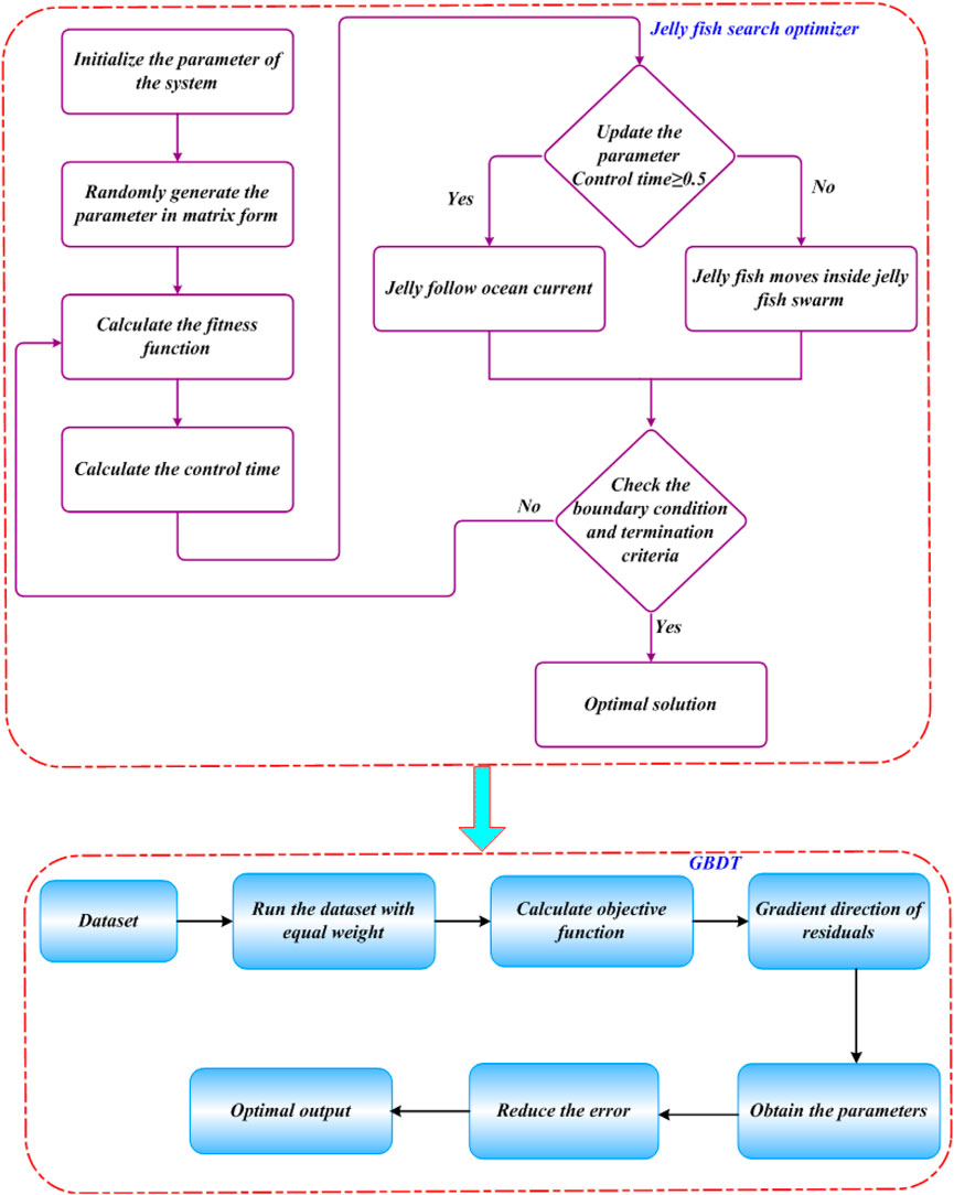
Figure 8. Flowchart of the JS–GBDT technique.
6.1 Case 1: analysis of the performance of the proposed method based on UPQC-EVCS in power quality control
The grid current and voltage analysis are displayed in Figure 9. The system’s voltage varies from −300 to 300 V at 0–0.5 s, as shown in subplot Figure 9A. The system’s current varies from −200 to 200 A at 0–0.2 s, as shown in subplot Figure 9B. The voltage is increased from 0.2 to 0.3 s; that is, the voltage sag is again changed to the normal of −200 to 200 A at 0.3–0.5 s. An investigation of load current and voltage is displayed in Figure 10. It is varied, like the grid voltage and current. An analysis of the SSC voltage is depicted in Figure 11. The system’s voltage varies from −70 to 70 V in 0–0.3 s. At 0.3–0.4 s, the voltage is increased from −99 to 99 V. At 0.4–0.5 s, it again varied from −70 to 70 V.
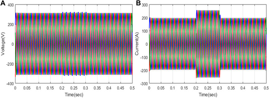
Figure 9. Investigation of the grid: (A) voltage and (B) current.
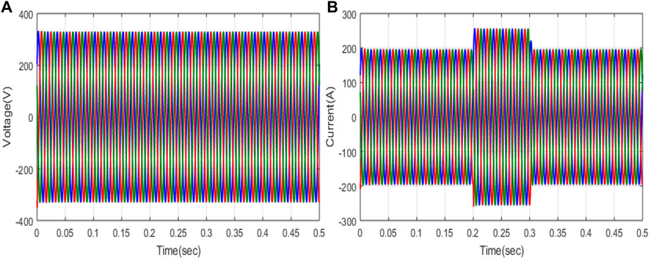
Figure 10. Investigation of the load: (A) voltage and (B) current.
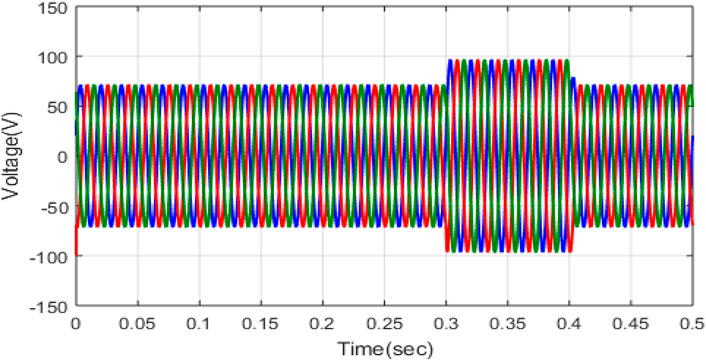
Figure 11. Investigation of the SSC voltage.
An investigation of phase A (a) grid voltage, load, and SSC and (b) grid current, load, and PSC is displayed in Figure 12. An analysis of the voltage of the grid, load, and SSC is illustrated in subplot Figure 12A. Here, blue represents the load voltage; green represents the SSC voltage, and red represents the grid voltage. The load and grid voltage are nearly the same, and the SSC voltage becomes 0 at 0–0.3 s. At 0.3 s, the SSC voltage varies from −100 to 100 V at 0–0.4 s. An analysis of the current of the grid, load, and PSC is illustrated in subplot Figure 12B. Here, blue represents the load current, green represents the PSC current, and red represents the grid current. The sag occurred at 0.2 to 0.2 s using the proposed technique; the sag is compensated and provides the optimal output. At the sag condition, the current of PSC varies from −100 to 100 A at 0.2–0.3 s.
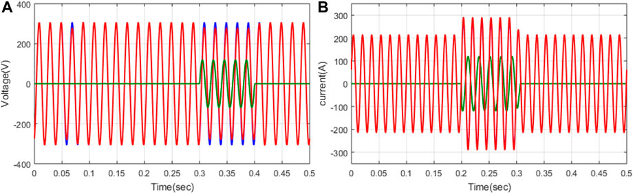
Figure 12. Investigation of phase A (A) voltage of grid, load, and SSC and phase B (B) current of the grid, load, and PSC.
6.2 Case 2: performance investigation of the proposed method based on V2G-UPQC with the lowest volt–ampere effectiveness
An analysis of the hybrid technique based on the V2G connection with minimum volt–ampere loading is conducted. The comments of grid voltage and current are displayed in Figure 13. The grid voltage is represented as the subplot in Figure 13A. The voltage varies from −300 to 300 V at 0–0.1 s, and then a swell occurs at 0.1–0.4 s; that is, the voltage lessens from −250 to 250 V. Again, the voltage is increased at a particular range. The current of the grid is displayed in the subplot of Figure 13B. The current varies from −500 to 500 A from 0 s to 0.1 s. Again, it increases to 900 A at 0.1 s–0.2 s and then reduces step by step, and finally, the current varies from −500 to 500 A at 0.4–0.5 s. An analysis of load current and voltage is displayed in Figure 15. Load voltage is represented as a subplot in Figure 14A. The voltage varies from −300 to 300 V at 0–0.5 s. The load current is represented in the subplot of Figure 14B. The current varies from −900 to 900 A at 0 s–0.5 s. An investigation of (a) SSC voltage and (b) PSC current is displayed in Figure 15. SSC voltage varies, and sags are compensated using offset voltage generation. The PSC current varies from −250 to 250 A at 0–0.1 s, and then it is reduced and varies from −180 to 180 A at 0.2–0.3 s.
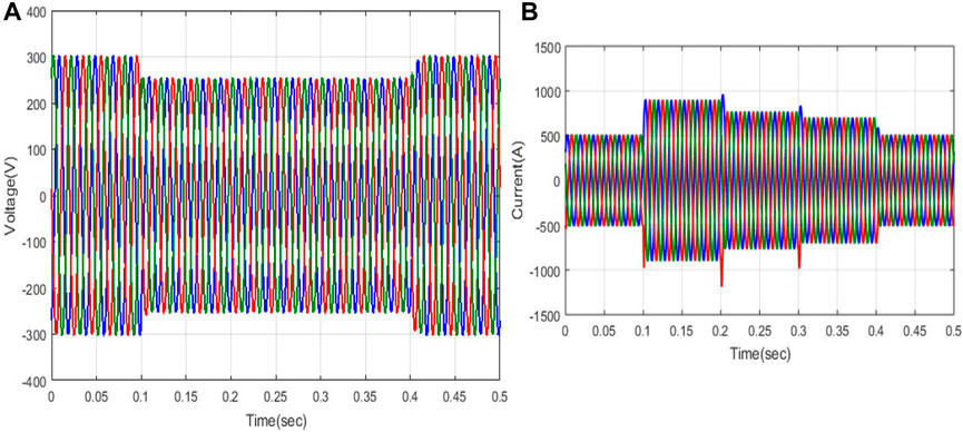
Figure 13. Analysis of the grid: (A) voltage and (B) current.
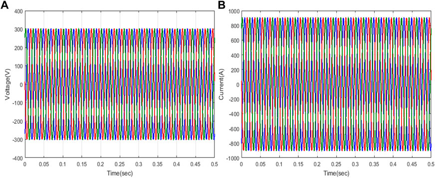
Figure 14. Investigation of the load: (A) voltage and (B) current.
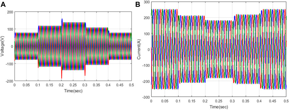
Figure 15. Investigation of (A) SSC voltage and (B) PSC current.
An analysis of DC voltage control is displayed in Figure 16. From Figure 16, it is proven that the SMES controls the DC voltage. Without SMES, the DC voltage is highly varied. Using SMES, the voltage is constant, i.e., 800 V at 0.2 s–1 s. An analysis of the active and reactive power of (a) PSC and (b) SSC is displayed in Figure 17. The active power of PSC is higher than that of the active and reactive power. In addition, the SSC provides high active power. An analysis of the active power and reactive power on the load and grid power on the PV and EV is displayed in Figure 18. The reactive power of the grid is zero, but the reactive power of the load is 100 W. The active power of the load is 300 W, and the active power of the grid varies from 200 to 270 W. Hence, using the proposed technique, high power of the system is obtained, and it reduces the burden on the grid using EVs. The power of the PV and EV is displayed in Figure 18B. The PV power is −80 kW, and EV1 and EV2 are charging at rated power.
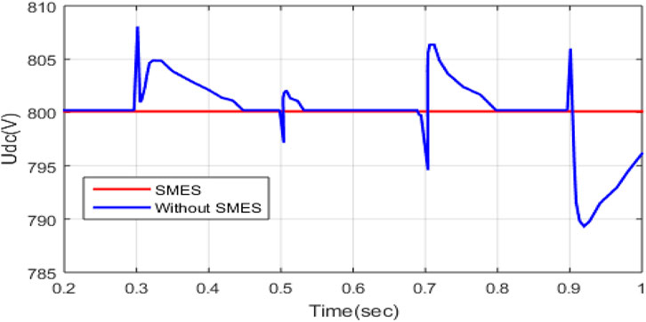
Figure 16. Analysis of DC voltage control.
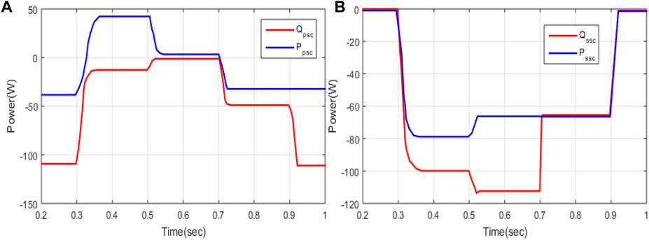
Figure 17. Analysis of the active power and reactive power of (A) PSC and (B) SSC.
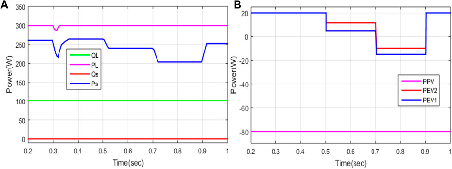
Figure 18. Analysis of the (A) active and reactive power of the load and grid and (B) power of PV and EV.
6.3 Case 3: performance analysis of the proposed technique based on UPQC under compensation mode and condition changes
An analysis of the performance of the proposed technique is conducted based on UPQC under compensation mode and conditional changes. An analysis of grid voltage and current is displayed in Figure 19. The grid voltage is represented as a subplot of Figure 19A. The voltage varies from −300 to 300 V at 0–0.1 s, swells at 0.1–0.2 s, and then reduces to −250 to 250 V in 0.2–0.4 s. Again, the voltage is increased in a certain range. The current of the grid is displayed in the subplot of Figure 19B. The current varies from −400 to 400 A at 0 s–0.1 s. Again, it increases to 700 A at 0.1 s–0.2 s, then it reduces step by step, and finally, the current varies from −400 to 400 A at 0.4–0.5 s. An analysis of load current and voltage is displayed in Figure 20. Load voltage is represented as a subplot in Figure 20A. The voltage varies from −300 to 300 V at 0–0.5 s. The current load is displayed in the subplot of Figure 20B. The current varies from −900 to 900 A at 0–0.5 s. The voltage of the SSC and current of the PSC are displayed in Figure 21. The SSC voltage varies, and sags are compensated using the compensated voltage generation. The PSC current varies from −300 to 300 A at 0–0.1 s, and then it reduces and varies from −200 to 200 A at 0.1–0.2 s. An analysis of phase A voltage and current for grid load and SSC is displayed in Figure 22A. Here, blue represents the load voltage, green represents the SSC voltage, and red represents the grid voltage. The load and grid voltage are nearly the same, and the SSC voltage becomes 0 at 0–0.1 s. SSC voltage varies from −100 to 100 V at 0.1–0.7 s.
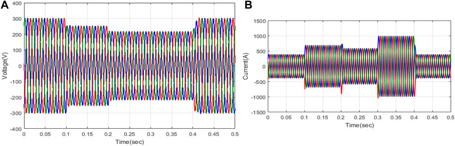
Figure 19. Analysis of the grid: (A) voltage and (B) current.
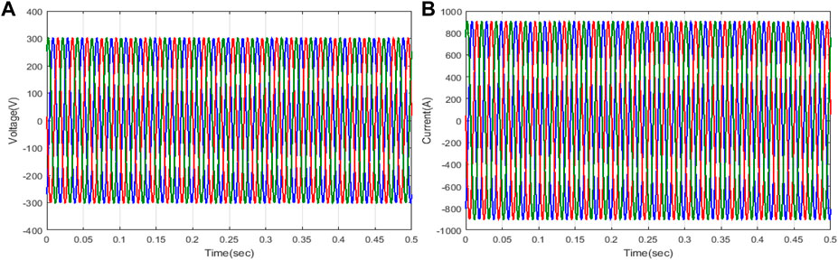
Figure 20. Investigation of the load: (A) voltage and (B) current.
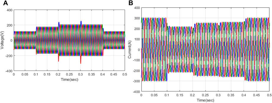
Figure 21. Investigation of (A) SSC voltage and (B) PSC current.

Figure 22. Analysis of phase A (A) voltage of grid, load, and SSC. (B) Analysis of DC voltage control.
An analysis of DC voltage control is displayed in Figure 22B. The SMES controls the DC voltage, as shown in Figure 23. Without SMES, the DC voltage is highly varied. Using SMES, the voltage is constant, i.e., 800 V at 0.2 s–1 s. An analysis of the active powers and reactive powers of PSC and SSC is displayed in Figure 23. Compared to both active and reactive power, the active power of PSC is high. In addition, the SSC provides high active power. An analysis of the active powers and reactive powers for the load side, grid side, and power for the PV and EV is displayed in Figure 24. The reactive powers of the grid are 0, but the reactive powers of the load are 110 W. The active power of the load is 300 W, and the grid’s active power varies from 200 to 260 W. Hence, the proposed technique obtains high power and reduces the burden on the grid using EVs. The power of the PV and EV is displayed in Figure 24B. The powers of the PV are varied up to −20 when EV1 and EV2 are charging at rated power. THD of the proposed technique is 0.9%, and for the existing processes, such as GWO, ATLA, and NPO, THD becomes 4.32%, 2.08%, and 1.43%, respectively, as recorded in Table 1. This concludes that the proposed technique has lower THD than that in the existing literature.
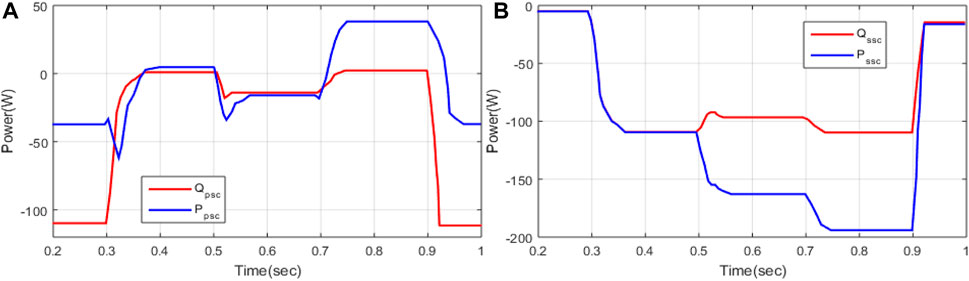
Figure 23. Analysis of the active and reactive powers of (A) PSC and (B) SSC.
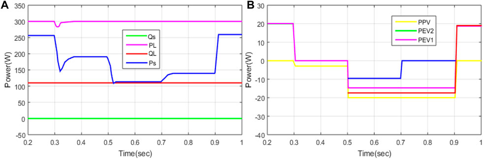
Figure 24. Analysis of (A) active and reactive powers of the load and grid and (B) power for PV and EV.

Table 1. Percentage of THD by various methods.
7 Conclusion
This manuscript proposes a hybrid GBDT–JS technique for increasing power quality. The proposed system is incorporated into UPQC, EVCS, PV, and SMES. The UPQC is utilized to control the direct current of voltage, voltage fluctuation, and current at the grid side. Using the proposed approach, the UPQC converters are controlled and provide an optimal outcome. In addition, various controls of the system’s voltage, current, and THD are minimized. Moreover, the proposed approach is utilized to solve the grid integration problem with PV and EVs controlling the power on both the load and grid sides. The battery of the EV is protected by a battery management system that allocates power based on SOC. SMES is utilized to maintain stable DC power. This proposed technique is implemented in MATLAB or Simulink tool, and the performance of the proposed technique is compared with various existing methods, such as GWO, ATLA, and NPO. This proposed technique is examined in three cases: control power quality problem, V2G function-based analysis, and compensation mode with condition changes. The simulation outcome concludes that the power quality problems, like the compensation of active power support of reactive power, are effectively solved using the proposed technique. The simulation results show that the proposed technique’s THD is 0.9%, which is lower than that of the existing techniques, such as GWO (4.32%), ATLA (2.08%), and NPO (1.43%). The losses under the sag condition are minimized using the proposed method.
Data availability statement
The original contributions presented in the study are included in the article/Supplementary Material; further inquiries can be directed to the corresponding author.
Author contributions
CP: conceptualization, data curation, formal analysis, investigation, methodology, project administration, software, validation, visualization, and writing–original draft. AP: conceptualization, formal analysis, funding acquisition, investigation, methodology, visualization, and writing–original draft. CR: data curation, formal analysis, methodology, project administration, and writing–original draft. MB: conceptualization, data curation, investigation, methodology, software, writing–original draft, and conceptualization. JM: funding acquisition, methodology, resources, software, validation, and writing–review and editing. MS: funding acquisition, resources, supervision, validation, and writing–review and editing.
Funding
The author(s) declare that no financial support was received for the research, authorship, and/or publication of this article.
Conflict of interest
The authors declare that the research was conducted in the absence of any commercial or financial relationships that could be construed as a potential conflict of interest.
The author(s) declared that they were an editorial board member of Frontiers, at the time of submission. This had no impact on the peer review process and the final decision.
Publisher’s note
All claims expressed in this article are solely those of the authors and do not necessarily represent those of their affiliated organizations, or those of the publisher, the editors, and the reviewers. Any product that may be evaluated in this article, or claim that may be made by its manufacturer, is not guaranteed or endorsed by the publisher.
References
Afzal, M. Z., Aurangzeb, M., Iqbal, S., Pushkarna, M., Rehman, A. U., Kotb, H., et al. (2023). A novel electric vehicle battery management system using an artificial neural network-based adaptive droop control theory. Int. J. Energy Res. 2023, 1–15. doi:10.1155/2023/2581729
Al Balushi, K. (2020). Optimal location and sizing of UPQC for improving power system quality. J. Comput. Mech. Power Syst. Control 3 (2), 26–32. doi:10.46253/jcmps.v3i2.a4
Amini, M., and Jalilian, A. (2021). Optimal sizing and location of open-UPQC in distribution networks considering load growth. Int. J. Electr. Power and Energy Syst. 130, 106893. doi:10.1016/j.ijepes.2021.106893
Aymen, F., Alowaidi, M., Bajaj, M., Sharma, N. K., Mishra, S., and Sharma, S. K. (2021). Electric vehicle model based on multiple recharge system and a particular traction motor conception. IEEE Access 9, 49308–49324. doi:10.1109/access.2021.3068262
Bai, J., Gu, W., Yuan, X., Li, Q., Xue, F., and Wang, X. (2015). Power quality prediction, early warning, and control for points of Common coupling with wind farms. Energies 8 (9), 9365–9382. doi:10.3390/en8099365
Bai, X., Xu, M., Li, Q., and Yu, L. (2022). Trajectory-battery integrated design and its application to orbital maneuvers with electric pump-fed engines. Adv. Space Res. 70 (3), 825–841. doi:10.1016/j.asr.2022.05.014
Balan, G., Arumugam, S., Muthusamy, S., Panchal, H., Kotb, H., Bajaj, M., et al. (2022). An improved deep learning-based technique for driver detection and driver assistance in electric vehicles with better performance. Int. Trans. Electr. Energy Syst. 2022, 1–16. doi:10.1155/2022/8548172
Campanhol, L., da Silva, S., de Oliveira, A., and Bacon, V. (2019). Power flow and stability analyses of a multifunctional distributed generation system integrating a photovoltaic system with unified power quality conditioner. IEEE Trans. Power Electron. 34 (7), 6241–6256. doi:10.1109/tpel.2018.2873503
Cardoso, G., Stadler, M., Bozchalui, M., Sharma, R., Marnay, C., Barbosa-Póvoa, A., et al. (2014). Optimal investment and scheduling of distributed energy resources with uncertainty in electric vehicle driving schedules. Energy 64, 17–30. doi:10.1016/j.energy.2013.10.092
Chou, J., and Truong, D. (2021). A novel metaheuristic optimizer inspired by behavior of jellyfish in ocean. Appl. Math. Comput. 389, 125535. doi:10.1016/j.amc.2020.125535
Crosier, R., and Wang, S. (2013). DQ-frame modeling of an active power filter integrated with a grid-connected, multifunctional electric vehicle charging station. IEEE Trans. Power Electron. 28 (12), 5702–5716. doi:10.1109/tpel.2013.2245515
Devassy, S., and Singh, B. (2017). Modified pq-theory-based control of solar-PV-integrated UPQC-S. IEEE Trans. Ind. Appl. 53 (5), 5031–5040. doi:10.1109/tia.2017.2714138
Devassy, S., and Singh, B. (2018). Design and performance analysis of three-phase solar PV integrated UPQC. IEEE Trans. Ind. Appl. 54 (1), 73–81. doi:10.1109/tia.2017.2754983
Dharavat, N., Sudabattula, S. K., Velamuri, S., Mishra, S., Sharma, N. K., Bajaj, M., et al. (2022). Optimal allocation of renewable distributed generators and electric vehicles in a distribution system using the political optimization algorithm. Energies 15 (18), 6698. doi:10.3390/en15186698
Di Giorgio, A., Liberati, F., and Canale, S. (2014). Electric vehicles charging control in a smart grid: a model predictive control approach. Control Eng. Pract. 22, 147–162. doi:10.1016/j.conengprac.2013.10.005
Ding, Z., Wu, X., Chen, C., and Yuan, X. (2023). Magnetic field analysis of surface-mounted permanent magnet motors based on an improved conformal mapping method. IEEE Trans. Industry Appl. 59 (2), 1689–1698. doi:10.1109/TIA.2022.3228509
Diong, B., Sepahvand, H., and Corzine, K. A. (2013). Harmonic distortion optimization of cascaded H-bridge inverters considering device voltage drops and noninteger DC voltage ratios. IEEE Trans. Ind. Electron. 60, 3106–3114. doi:10.1109/tie.2012.2202351
Duan, Y., Zhao, Y., and Hu, J. (2023). An initialization-free distributed algorithm for dynamic economic dispatch problems in microgrid: modeling, optimization and analysis. Sustain. Energy, Grids Netw. 34, 101004. doi:10.1016/j.segan.2023.101004
Gao, Y., Doppelbauer, M., Ou, J., and Qu, R. (2022). Design of a double-side flux modulation permanent magnet machine for servo application. IEEE J. Emerg. Sel. Top. Power Electron. 10 (2), 1671–1682. doi:10.1109/JESTPE.2021.3105557
Gowrishankar, A., and Ramasamy, M. (2019). SPV-based UPQC with modified power angle control scheme for the enhancement of power quality. J. Circuits, Syst. Comput. 29 (04), 2050064. doi:10.1142/s0218126620500644
Hamed, S. B., Abid, A., Hamed, M. B., Sbita, L., Bajaj, M., Ghoneim, S. S., et al. (2023). A robust MPPT approach based on first-order sliding mode for triple-junction photovoltaic power system supplying electric vehicle. Energy Rep. 9, 4275–4297. doi:10.1016/j.egyr.2023.02.086
Hamed, S. B., Hamed, M. B., Sbita, L., Bajaj, M., Blazek, V., Prokop, L., et al. (2022). Robust optimization and power management of a triple junction photovoltaic electric vehicle with battery storage. Sensors 22 (16), 6123. doi:10.3390/s22166123
Hegazy, O., Barrero, R., Van Mierlo, J., Lataire, P., Omar, N., and Coosemans, T. (2013). An advanced power electronics interface for electric vehicles applications. IEEE Trans. Power Electron. 28 (12), 5508–5521. doi:10.1109/tpel.2013.2256469
Huang, N., Chen, Q., Cai, G., Xu, D., Zhang, L., and Zhao, W. (2021). Fault diagnosis of bearing in wind turbine gearbox under actual operating conditions driven by limited data with noise labels. IEEE Trans. Instrum. Meas. 70, 1–10. Art no. 3502510. doi:10.1109/TIM.2020.3025396
Jaraniya, D., and Kumar, S. (2021). Grid interactive charging station using ZAJO-NLMS adaptive filtering technique with improved power quality for EV applications. J. Institution Eng. (India) Ser. B. doi:10.1007/s40031-021-00689-0
Jargstorf, J., and Wickert, M. (2013). Offer of secondary reserve with a pool of electric vehicles on the German market. Energy Policy 62, 185–195. doi:10.1016/j.enpol.2013.06.088
Jian, L., Zhu, X., Shao, Z., Niu, S., and Chan, C. (2014). A scenario of vehicle-to-grid implementation and its double-layer optimal charging strategy for minimizing load variance within regional smart grids. Energy Convers. Manag. 78, 508–517. doi:10.1016/j.enconman.2013.11.007
Jiang, Z., and Xu, C. (2023). Policy incentives, government subsidies, and technological innovation in new energy vehicle enterprises: evidence from China. Energy Policy 177, 113527. doi:10.1016/j.enpol.2023.113527
Jiang, Z., and Xu, C. (2024). Disrupting the technology innovation efficiency of manufacturing enterprises through digital technology promotion: an evidence of 5G technology construction in China. IEEE Trans. Eng. Manag., 1–11. doi:10.1109/TEM.2023.3261940
Jin, J., Li, H., Yang, R., Li, Y., Zhou, Q., Feng, G., et al. (2022). An improved compensation method for voltage sags and swells of the electric vehicles charging station based on a UPQC-SMES system. Int. J. Electr. Power Energy Syst. 143, 108501. Article 108501. doi:10.1016/j.ijepes.2022.108501
Kakouche, K., Rekioua, T., Mezani, S., Oubelaid, A., Rekioua, D., Blazek, V., et al. (2022). Model predictive direct torque control and fuzzy logic energy management for multi power source electric vehicles. Sensors 22 (15), 5669. doi:10.3390/s22155669
Kannan, R., Chandramohan, K., and Ghanta, D. (2022). Energy management in plugin hybrid electric vehicles with hybrid energy storage system using hybrid approach. Energy Technol. 10, 2200355. doi:10.1002/ente.202200355
Kar, P. K., Priyadarshi, A., Karanki, S. B., and Ruderman, A. (2021). Voltage and current THD minimization of a single-phase multilevel inverter with an arbitrary RL-load using a time-domain approach. IEEE J. Emerg. Sel. Top. Power Electron. 9 (6), 6817–6827. doi:10.1109/JESTPE.2021.3050787
Karanki, G., Mishra, M., and Kumar, B. (2013). A modified three-phase four-wire UPQC topology with reduced DC-link voltage rating. IEEE Trans. Industrial Electron. 60 (9), 3555–3566. doi:10.1109/tie.2012.2206333
Karthikeyan, B., Sundararaju, K., Palanisamy, R., Manivasagam, R., Hossain, I., Bajaj, M., et al. (2022). A dual input single output non-isolated DC-DC converter for multiple sources electric vehicle applications. Front. Energy Res. 10, 979539. doi:10.3389/fenrg.2022.979539
Khorasani, P., Joorabian, M., and Seifossadat, S. (2017). Smart grid realization with introducing unified power quality conditioner integrated with DC microgrid. Electr. Power Syst. Res. 151, 68–85. Available:. doi:10.1016/j.epsr.2017.05.023
Kraiem, H., Flah, A., Mohamed, N., Alowaidi, M., Bajaj, M., Mishra, S., et al. (2021). Increasing electric vehicle autonomy using a photovoltaic system controlled by particle swarm optimization. IEEE Access 9, 72040–72054. doi:10.1109/access.2021.3077531
Kumar, B. A., Jyothi, B., Rathore, R. S., Singh, A. R., and Bajaj, M. (2023). A novel framework for enhancing the power quality of electrical vehicle battery charging based on a modified Ferdowsi Converter. Energy Rep. 10, 2394–2416. doi:10.1016/j.egyr.2023.09.070
Kumar Kar, P., Priyadarshi, A., and Bhaskar Karanki, S. (2019). Selective harmonics elimination using whale optimisation algorithm for a single-phase-modified source switched multilevel inverter. IET Power Electron. 12 (8), 1952–1963. doi:10.1049/iet-pel.2019.0087
Lee, I., and Moon, G. (2014). Half-bridge integrated ZVS full-bridge converter with reduced conduction loss for electric vehicle battery chargers. IEEE Trans. Industrial Electron. 61 (8), 3978–3988. doi:10.1109/tie.2013.2282608
Leemput, N., Geth, F., Van Roy, J., Olivella-Rosell, P., Driesen, J., and Sumper, A. (2015). MV and LV residential grid impact of combined slow and fast charging of electric vehicles. Energies 8 (3), 1760–1783. doi:10.3390/en8031760
Leon, A., Amodeo, S., Solsona, J., and Valla, M. (2011). Nonlinear optimal controller for unified power quality conditioners. IET Power Electron. 4 (4), 435. doi:10.1049/iet-pel.2010.0134
Li, P., Hu, J., Qiu, L., Zhao, Y., and Ghosh, B. K. (2022b). A distributed economic dispatch strategy for power–water networks. IEEE Trans. Control Netw. Syst. 9 (1), 356–366. doi:10.1109/TCNS.2021.3104103
Li, S., Zhao, X., Liang, W., Hossain, M. T., and Zhang, Z. (2022a). A fast and accurate calculation method of line breaking power flow based on taylor expansion. Front. Energy Res. 10. doi:10.3389/fenrg.2022.943946
Lin, X., Wen, Y., Yu, R., Yu, J., and Wen, H. (2022). Improved weak grids synchronization unit for passivity enhancement of grid-connected inverter. IEEE J. Emerg. Sel. Top. Power Electron. 10 (6), 7084–7097. doi:10.1109/JESTPE.2022.3168655
Liu, H., Hu, Z., Song, Y., and Lin, J. (2013b). Decentralized vehicle-to-grid control for primary frequency regulation considering charging demands. IEEE Trans. Power Syst. 28 (3), 3480–3489. doi:10.1109/tpwrs.2013.2252029
Liu, Q., Xiao, X., and Chen, Z. (2013a). Photovoltaic electric vehicle charging system with the function of active power filter. Adv. Mater. Res. 724-725, 1459–1464. Available at: https://doi.org/10.4028/www.scientific.net/AMR.724-725.1459.
Liu, S., and Liu, C. (2021a). Virtual-vector-based robust predictive current control for dual three-phase PMSM. IEEE Trans. Industrial Electron. 68 (3), 2048–2058. doi:10.1109/TIE.2020.2973905
Liu, S., and Liu, C. (2021b). Direct harmonic current control scheme for dual three-phase PMSM drive system. IEEE Trans. Power Electron. 36 (10), 11647–11657. doi:10.1109/TPEL.2021.3069862
Mansor, M., Hasan, K., Othman, M., Noor, S., and Musirin, I. (2020). Construction and performance investigation of three-phase solar PV and battery energy storage system integrated UPQC. IEEE Access 8, 103511–103538. doi:10.1109/access.2020.2997056
Meng, L., Ma, L., Zhu, W., Yan, H., Wang, T., Mao, W., et al. (2022). Control strategy of single-phase UPQC for suppressing the influences of low-frequency DC-link voltage ripple. IEEE Trans. Power Electron. 37 (2), 1–2124. doi:10.1109/tpel.2021.3106049
Millnitz dos Santos, R., da Cunha, J., and Mezaroba, M. (2014). A simplified control technique for a dual unified power quality conditioner. IEEE Trans. Industrial Electron. 61 (11), 5851–5860. doi:10.1109/tie.2014.2314055
Mohamed, N., Aymen, F., Issam, Z., Bajaj, M., Ghoneim, S. S. M., and Ahmed, M. (2021). The impact of coil position and number on wireless system performance for electric vehicle recharging. Sensors 21 (13), 4343. doi:10.3390/s21134343
Mohanty, S., Panda, S., Parida, S. M., Rout, P. K., Sahu, B. K., Bajaj, M., et al. (2022). Demand side management of electric vehicles in smart grids: a survey on strategies, challenges, modeling, and optimization. Energy Rep. 8, 12466–12490. doi:10.1016/j.egyr.2022.09.023
Moreno, V., Pigazo, A., Liserre, M., and Dell’ Aquila, A. (2008). Unified power quality conditioner (UPQC) with voltage dips and over-voltages compensation capability. Renew. Energy Power Qual. J. 1 (06), 294–299. Available:. doi:10.24084/repqj06.285
Oubelaid, A., Taib, N., Rekioua, T., Bajaj, M., Blazek, V., Prokop, L., et al. (2022b). Multi source electric vehicles: smooth transition algorithm for transient ripple minimization. Sensors 22 (18), 6772. doi:10.3390/s22186772
Oubelaid, A., Taib, N., Rekioua, T., Bajaj, M., Yadav, A., Shouran, M., et al. (2022a). Secure power management strategy for direct torque controlled fuel cell/supercapacitor electric vehicles. Front. Energy Res. 10, 971357. doi:10.3389/fenrg.2022.971357
Pal, Y., Swarup, A., and Singh, B. (2012). A novel control strategy of three-phase, four-wire UPQC for power quality improvement. J. Electr. Eng. Technol. 7 (1), 1–8. doi:10.5370/jeet.2012.7.1.1
Panchanathan, S., Vishnuram, P., Rajamanickam, N., Bajaj, M., Blazek, V., Prokop, L., et al. (2023). A comprehensive review of the bidirectional converter topologies for the vehicle-to-grid system. Energies 16 (5), 2503. doi:10.3390/en16052503
Pang, C., Dutta, P., and Kezunovic, M. (2012). BEVs/PHEVs as dispersed energy storage for V2B uses in the smart grid. IEEE Trans. Smart Grid 3 (1), 473–482. doi:10.1109/tsg.2011.2172228
Patel, A., Mathur, H., and Bhanot, S. (2020). Enhancing VA sharing between the shunt and series APFs of UPQC with a modified SRF-PAC method. IET Power Electron. 13 (2), 275–285. doi:10.1049/iet-pel.2018.6329
Ravindran, M. A., Nallathambi, K., Vishnuram, P., Rathore, R. S., Bajaj, M., Rida, I., et al. (2023). A novel technological review on fast charging infrastructure for electrical vehicles: challenges, solutions, and future research directions. Alexandria Eng. J. 82, 260–290. doi:10.1016/j.aej.2023.10.009
Rekik, M., and Krichen, L. (2021). Photovoltaic and plug-in electric vehicle for smart grid power quality enhancement. Arabian J. Sci. Eng. 46 (2), 1481–1497. doi:10.1007/s13369-020-05155-5
Rezaee, S., Farjah, E., and Khorramdel, B. (2013). Probabilistic analysis of plug-in electric vehicles impact on electrical grid through homes and parking lots. IEEE Trans. Sustain. Energy 4 (4), 1024–1033. doi:10.1109/tste.2013.2264498
Roberge, V., Tarbouchi, M., and Labonte, G. (2015). Parallel algorithm on graphics processing unit for harmonic minimization in multilevel inverters. IEEE Trans. Ind. Inf. 11 (3), 700–707. doi:10.1109/tii.2015.2426057
Roberge, V., Tarbouchi, M., and Okou, F. (2014). Strategies to accelerate harmonic minimization in multilevel inverters using a parallel genetic algorithm on graphical processing unit. IEEE Trans. Power Electron. 29, 5087–5090. doi:10.1109/tpel.2014.2311737
Routray, A., Kumar Singh, R., and Mahanty, R. (2019). Harmonic minimization in three-phase hybrid cascaded multilevel inverter using modified particle swarm optimization. IEEE Trans. Ind. Inf. 15 (8), 4407–4417. doi:10.1109/tii.2018.2883050
Sarita, K., Kumar, S., Vardhan, A. S. S., Elavarasan, R. M., Saket, R. K., Shafiullah, G. M., et al. (2020). Power enhancement with grid stabilization of renewable energy-based generation system using UPQC-FLC-EVA technique. IEEE Access 8, 207443–207464. doi:10.1109/access.2020.3038313
Shanmugam, Y., Narayanamoorthi, R., Vishnuram, P., Savio, D., Yadav, A., Bajaj, M., et al. (2023). Solar-powered five-leg inverter-driven quasi-dynamic charging for a slow-moving vehicle. Front. Energy Res. 11, 1115262. doi:10.3389/fenrg.2023.1115262
Sharifzadeh, M., Vahedi, H., Portillo, R., Franquelo, L. G., and Al-Haddad, K. (2019). Selective harmonic mitigation based self-elimination of triplen harmonics for single-phase five-level inverters. IEEE Trans. Power Electron. 34 (1), 86–96. doi:10.1109/tpel.2018.2812186
Shen, Y., Xie, J., He, T., Yao, L., and Xiao, Y. (2023). CEEMD-Fuzzy control energy management of hybrid energy storage systems in electric vehicles. IEEE Trans. Energy Convers. 39, 555–566. doi:10.1109/TEC.2023.3306804
Shirkhani, M., Tavoosi, J., Danyali, S., Sarvenoee, A. K., Abdali, A., Mohammadzadeh, A., et al. (2023). A review on microgrid decentralized energy/voltage control structures and methods. Energy Rep. 10, 368–380. doi:10.1016/j.egyr.2023.06.022
Srndovic, M., Familiant, Y., Grandi, G., and Ruderman, A. (2016). Time-domain minimization of voltage and current total harmonic distortion for a single-phase multilevel inverter with a staircase modulation. Energies 9 (10), 815. doi:10.3390/en9100815
S S, D., N B, M., and Subramaniam, U. (2021a). Artificial neural network based solar energy integrated unified power quality conditioner. Energy Sources, Part A Recovery, Util. Environ. Eff., 1–25. doi:10.1080/15567036.2021.1919247
S S, D., N B, M., and Subramaniam, U. (2021b). Artificial neural network based solar energy integrated unified power quality conditioner. Energy Sources, Part A Recovery, Util. Environ. Eff., 1–25. doi:10.1080/15567036.2021.1919247
Sun, G., Sheng, L., Luo, L., and Yu, H. (2022). Game theoretic approach for multipriority data transmission in 5G vehicular networks. IEEE Trans. Intelligent Transp. Syst. 23 (12), 24672–24685. doi:10.1109/TITS.2022.3198046
Sun, G., Song, L., Yu, H., Chang, V., Du, X., and Guizani, M. (2019). V2V routing in a VANET based on the autoregressive integrated moving average model. IEEE Trans. Veh. Technol. 68 (1), 908–922. doi:10.1109/TVT.2018.2884525
Tanaka, T., Sekiya, T., Tanaka, H., Okamoto, M., and Hiraki, E. (2013). Smart charger for electric vehicles with power-quality compensator on single-phase three-wire distribution feeders. IEEE Trans. Industry Appl. 49 (6), 2628–2635. doi:10.1109/tia.2013.2262915
Venkatesan, M., Rajamanickam, N., Vishnuram, P., Bajaj, M., Blazek, V., Prokop, L., et al. (2022). A review of compensation topologies and control techniques of bidirectional wireless power transfer systems for electric vehicle applications. Energies 15 (20), 7816. doi:10.3390/en15207816
Vinothkumar, V., and Kanimozhi, R. (2022). RETRACTED ARTICLE: power flow control and power quality analysis in power distribution system using UPQC based cascaded multi-level inverter with predictive phase dispersion modulation method. J. Ambient Intell. Humaniz. Comput. 12, 6445–6463. doi:10.1007/s12652-020-02253-y
Wang, Y., Chen, P., Yong, J., Xu, W., Xu, S., and Liu, K. (2022). A comprehensive investigation on the selection of high-pass harmonic filters. IEEE Trans. Power Deliv. 37 (5), 4212–4226. doi:10.1109/TPWRD.2022.3147835
Wang, Y., Jiang, X., Xie, X., Yang, X., and Xiao, X. (2021). Identifying sources of subsynchronous resonance using wide-area phasor measurements. IEEE Trans. Power Deliv. 36 (5), 3242–3254. doi:10.1109/TPWRD.2020.3037289
Wang, Z., and Wang, S. (2013). Grid power peak shaving and valley filling using vehicle-to-grid systems. IEEE Trans. Power Deliv. 28 (3), 1822–1829. doi:10.1109/tpwrd.2013.2264497
Xia, M., and Li, X. (2013). Design and implementation of a high quality power supply scheme for distributed generation in a micro-grid. Energies 6 (9), 4924–4944. Available:. doi:10.3390/en6094924
Yan, Z., and Wen, H. (2021). Electricity theft detection base on extreme gradient boosting in AMI. IEEE Trans. Instrum. Meas. 70, 1–9. Art no. 2504909. doi:10.1109/TIM.2020.3048784
Yang, R., Jin, J., Zhou, Q., Mu, S., and Abu-Siada, A. (2022). Superconducting magnetic energy storage based DC unified power quality conditioner with advanced dual control for DC-DFIG. J. Mod. Power Syst. Clean. Energy 10 (5), 1385–1400. doi:10.35833/mpce.2021.000354
Yang, R. H., and Jin, J. X. (2021). Unified power quality conditioner with advanced dual control for performance improvement of DFIG-based wind farm. IEEE Trans. Sustain. Energy 12 (1), 116–126. doi:10.1109/tste.2020.2985161
Yang, Y., Zhang, Z., Zhou, Y., Wang, C., and Zhu, H. (2023). Design of a simultaneous information and power transfer system based on a modulating feature of magnetron. IEEE Trans. Microw. Theory Tech. 71 (2), 907–915. doi:10.1109/TMTT.2022.3205612
Ye, J., Gooi, H. B., and Wu, F. (2018). Optimal design and control implementation of UPQC based on variable phase angle control method. IEEE Trans. Ind. Inf. 14 (7), 3109–3123. doi:10.1109/tii.2018.2834628
Zhang, L., Sun, C., Cai, G., and Koh, L. H. (2023). Charging and discharging optimization strategy for electric vehicles considering elasticity demand response. eTransportation 18, 100262. doi:10.1016/j.etran.2023.100262
Zhang, X., Lu, Z., Yuan, X., Wang, Y., and Shen, X. (2021). L2-Gain adaptive robust control for hybrid energy storage system in electric vehicles. IEEE Trans. Power Electron. 36 (6), 7319–7332. doi:10.1109/TPEL.2020.3041653
Zhong, Y., Xia, M., and Chiang, H. (2016a). Electric vehicle charging station microgrid providing unified power quality conditioner support to local power distribution networks. Int. Trans. Electr. Energy Syst. 27 (3), e2262. doi:10.1002/etep.2262
Zhong, Y., Xia, M., and Chiang, H. (2016b). Electric vehicle charging station microgrid providing unified power quality conditioner support to local power distribution networks. Int. Trans. Electr. Energy Syst. 27 (3), e2262. doi:10.1002/etep.2262
Zhong, Y., Xia, M., and Chiang, H. (2016c). Electric vehicle charging station microgrid providing unified power quality conditioner support to local power distribution networks. Int. Trans. Electr. Energy Syst. 27 (3), e2262. doi:10.1002/etep.2262
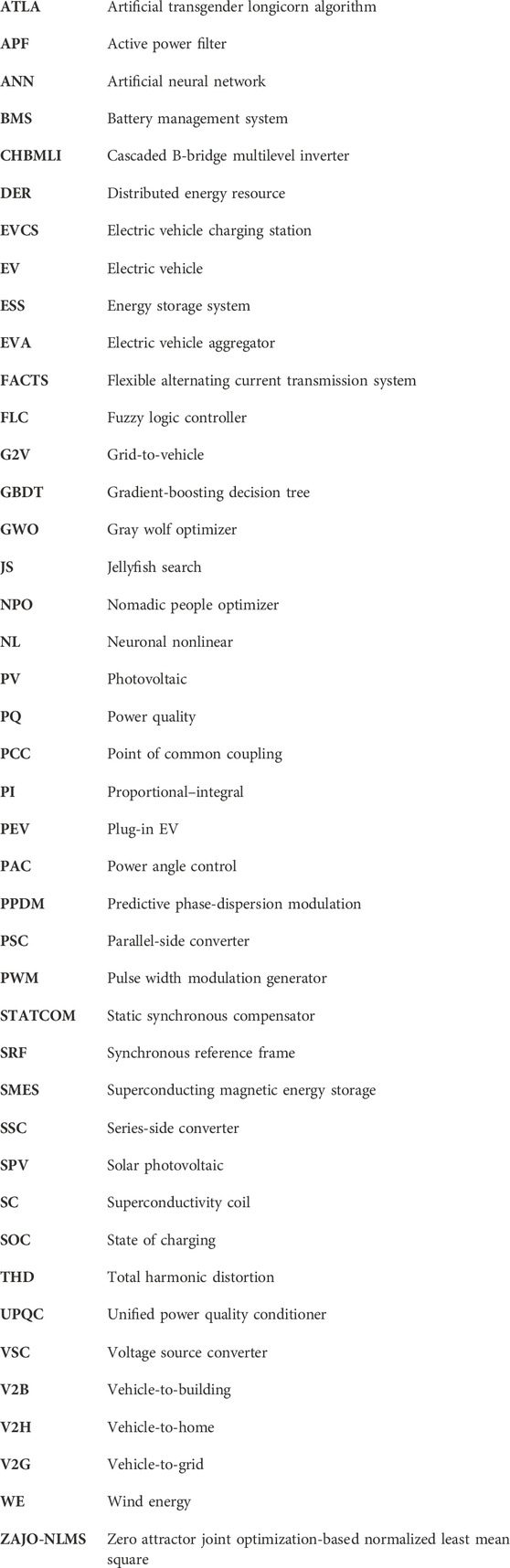
Glossary
Keywords: power quality, unified power quality conditioner, vehicles to grid function, electric vehicles charging station, total harmonic distortion
Citation: Prasada Rao CSV, Pandian A, Reddy CR, Bajaj M, Massoud J and Shouran M (2024) Unified power quality conditioner-based solar EV charging station using the GBDT–JS technique. Front. Energy Res. 12:1343635. doi: 10.3389/fenrg.2024.1343635
Received: 24 November 2023; Accepted: 20 March 2024;
Published: 11 April 2024.
Edited by:
Michael Carbajales-Dale, Clemson University, United StatesCopyright © 2024 Prasada Rao, Pandian, Reddy, Bajaj, Massoud and Shouran. This is an open-access article distributed under the terms of the Creative Commons Attribution License (CC BY). The use, distribution or reproduction in other forums is permitted, provided the original author(s) and the copyright owner(s) are credited and that the original publication in this journal is cited, in accordance with accepted academic practice. No use, distribution or reproduction is permitted which does not comply with these terms.
*Correspondence: Jabir Massoud, massoudj1@cardiff.ac.uk