Design and Implementation of a High Quality Power Supply Scheme for Distributed Generation in a Micro-Grid


Abstract
:1. Introduction
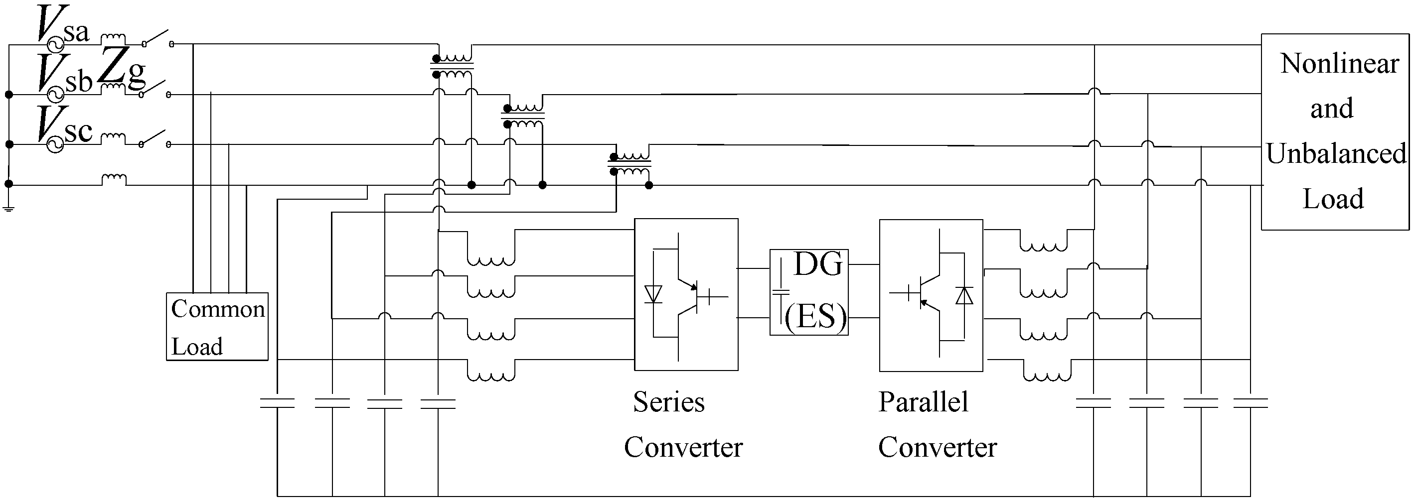
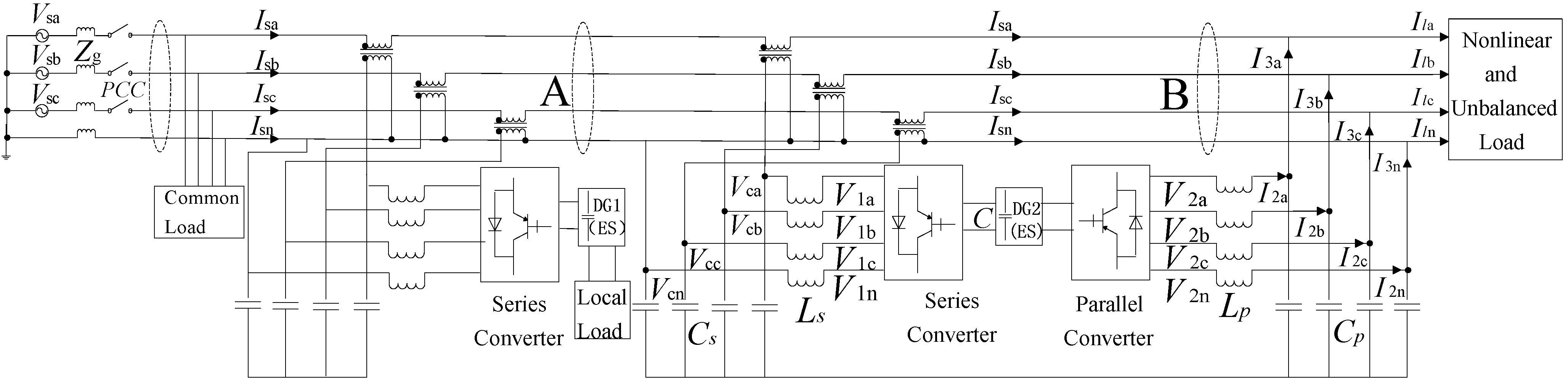
2. The Application of a Three-Phase Four-Leg Series—Parallel Converter in a Micro-Grid


3. The Structure and Control Strategy of a Micro-Grid
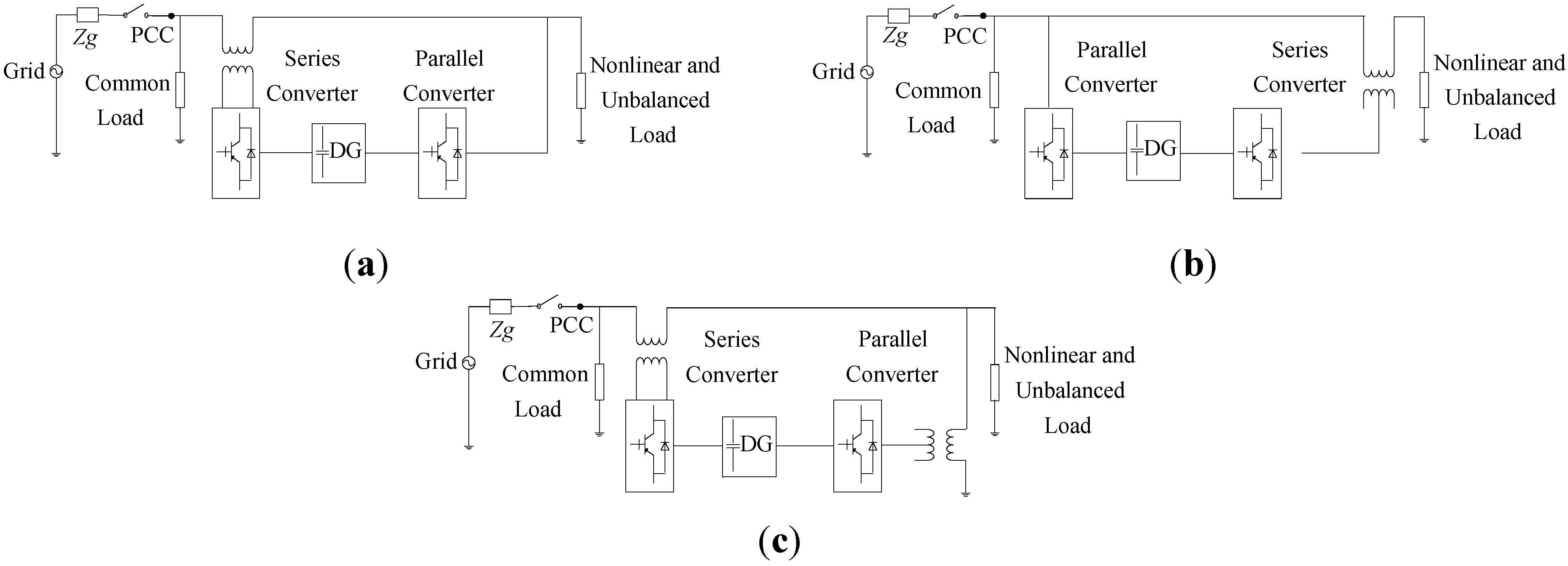
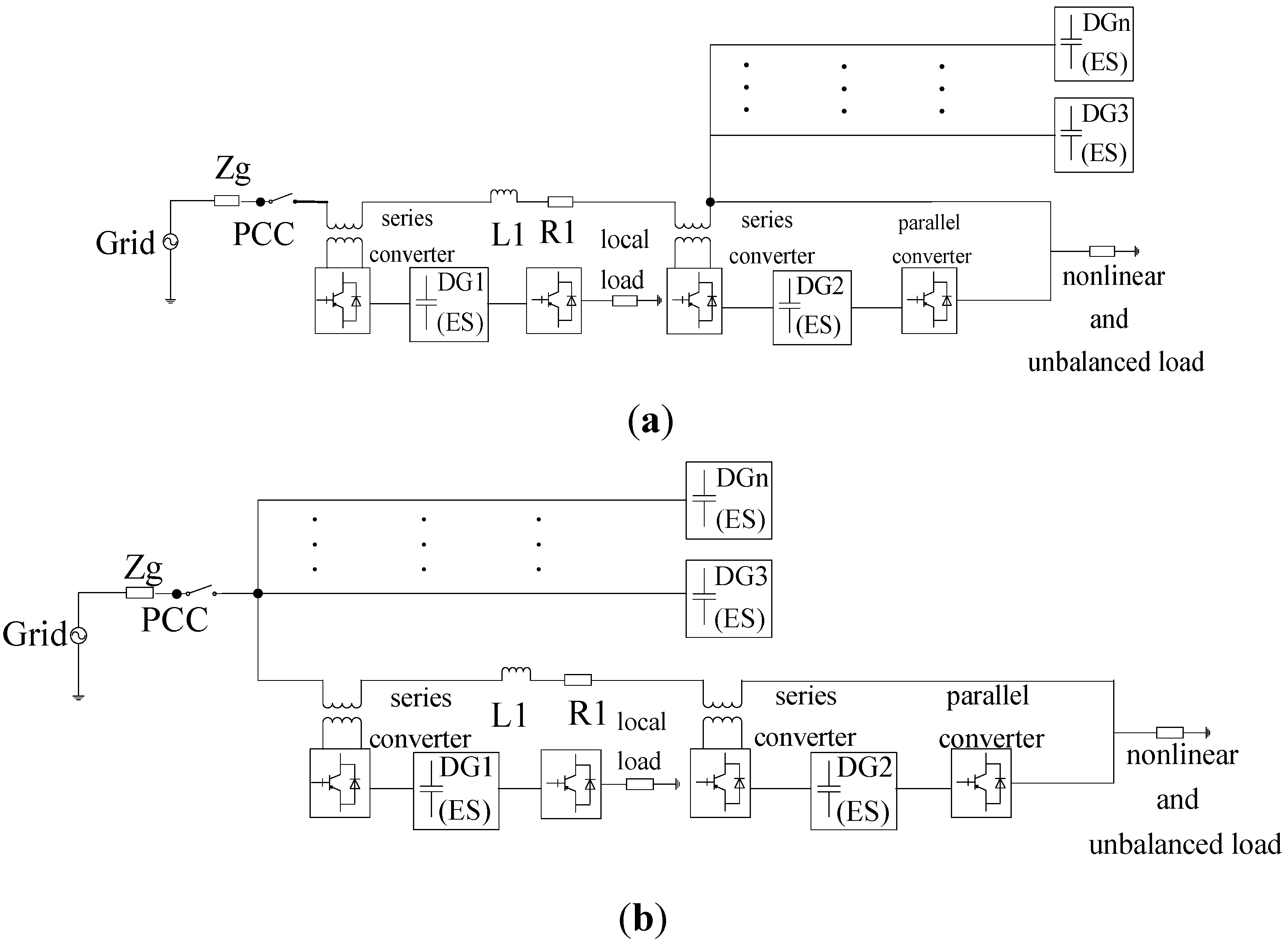
3.1. Existing Micro-Grid Architecture Based on UPQC

3.2. Conventional Voltage Sag Control Strategies of UPQC


(a) The Constant-Phase Voltage Compensation

(b) In-Phase Voltage Compensation

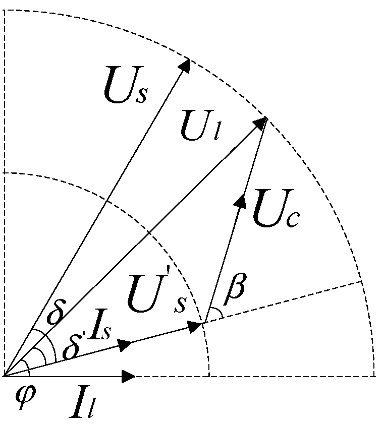
(c) The Minimum-Energy Compensation
4. The Improved Indirect Control Strategy Base on an Improved Structure of the UPQC
4.1. Micro-Grid Based on an Improved Structure of the UPQC


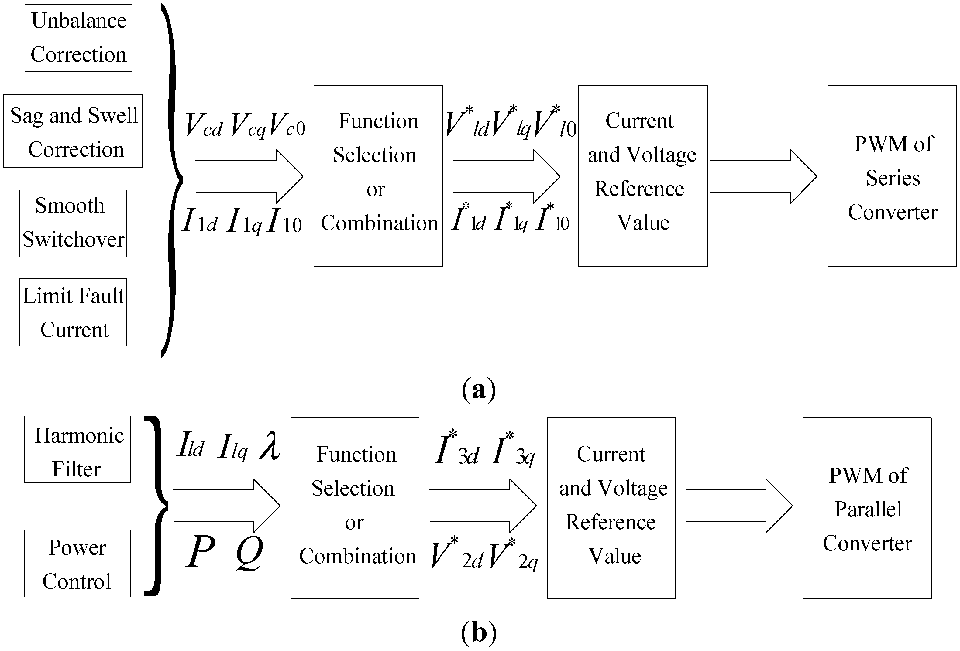
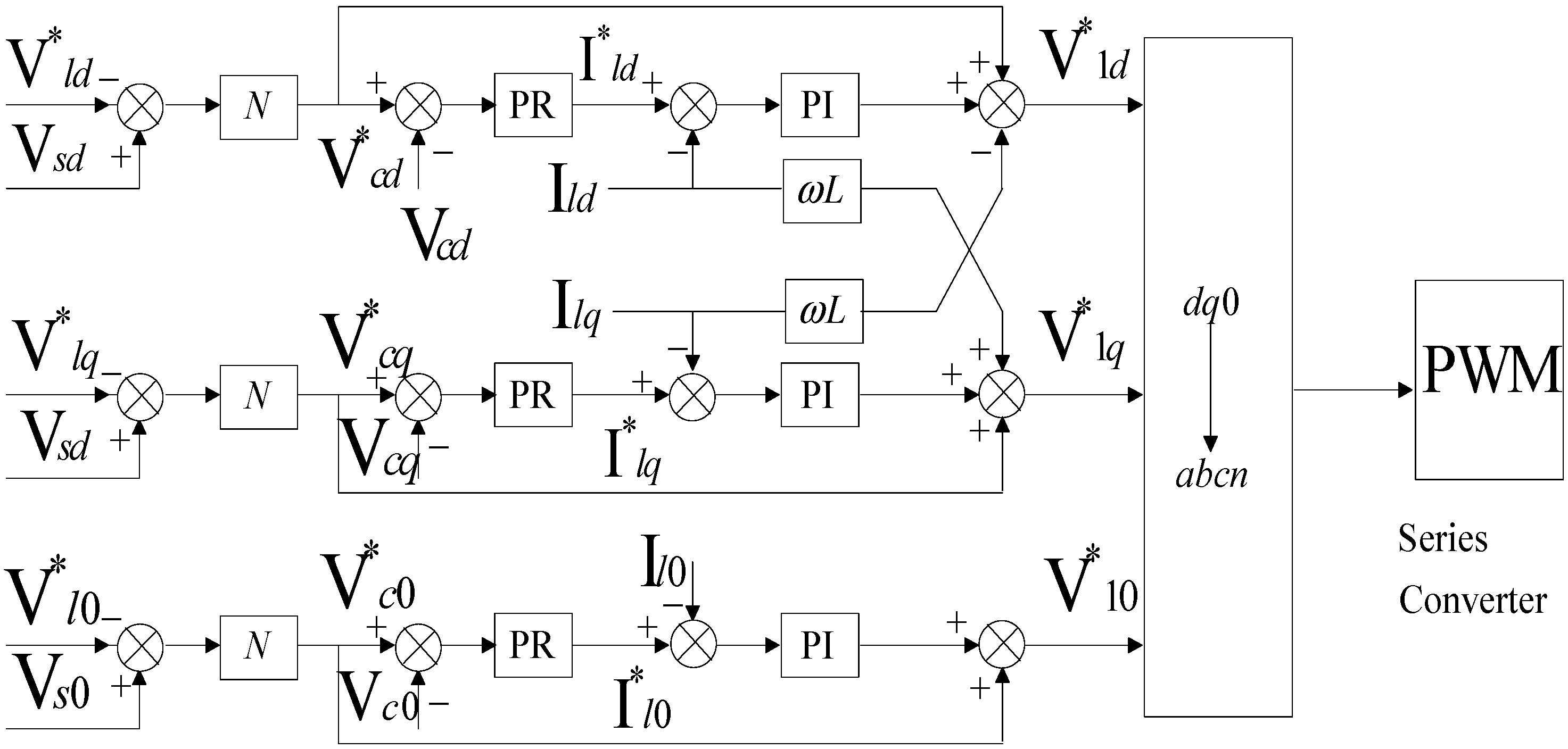
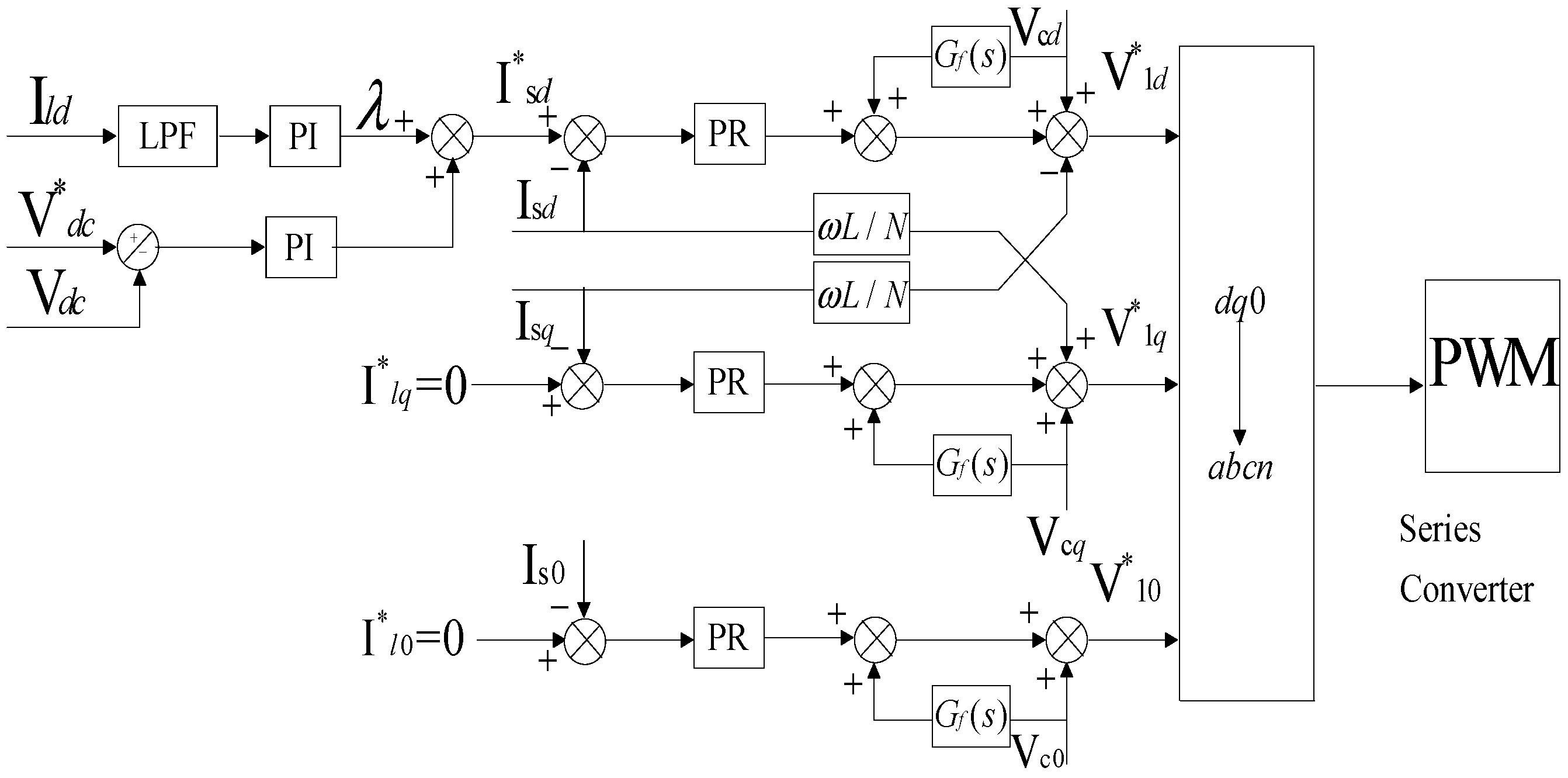
4.2. Control of the Series Converter


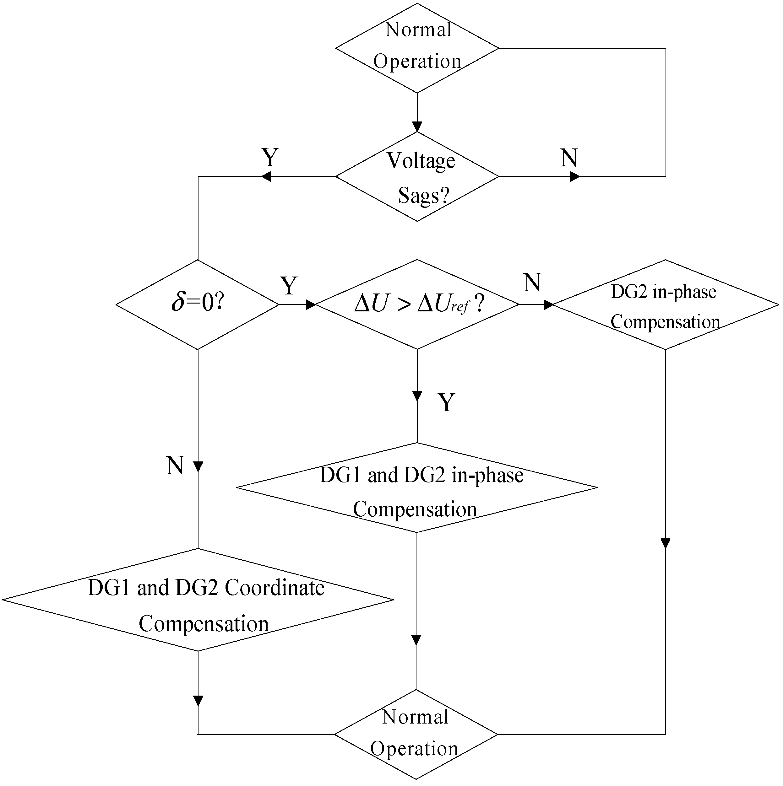
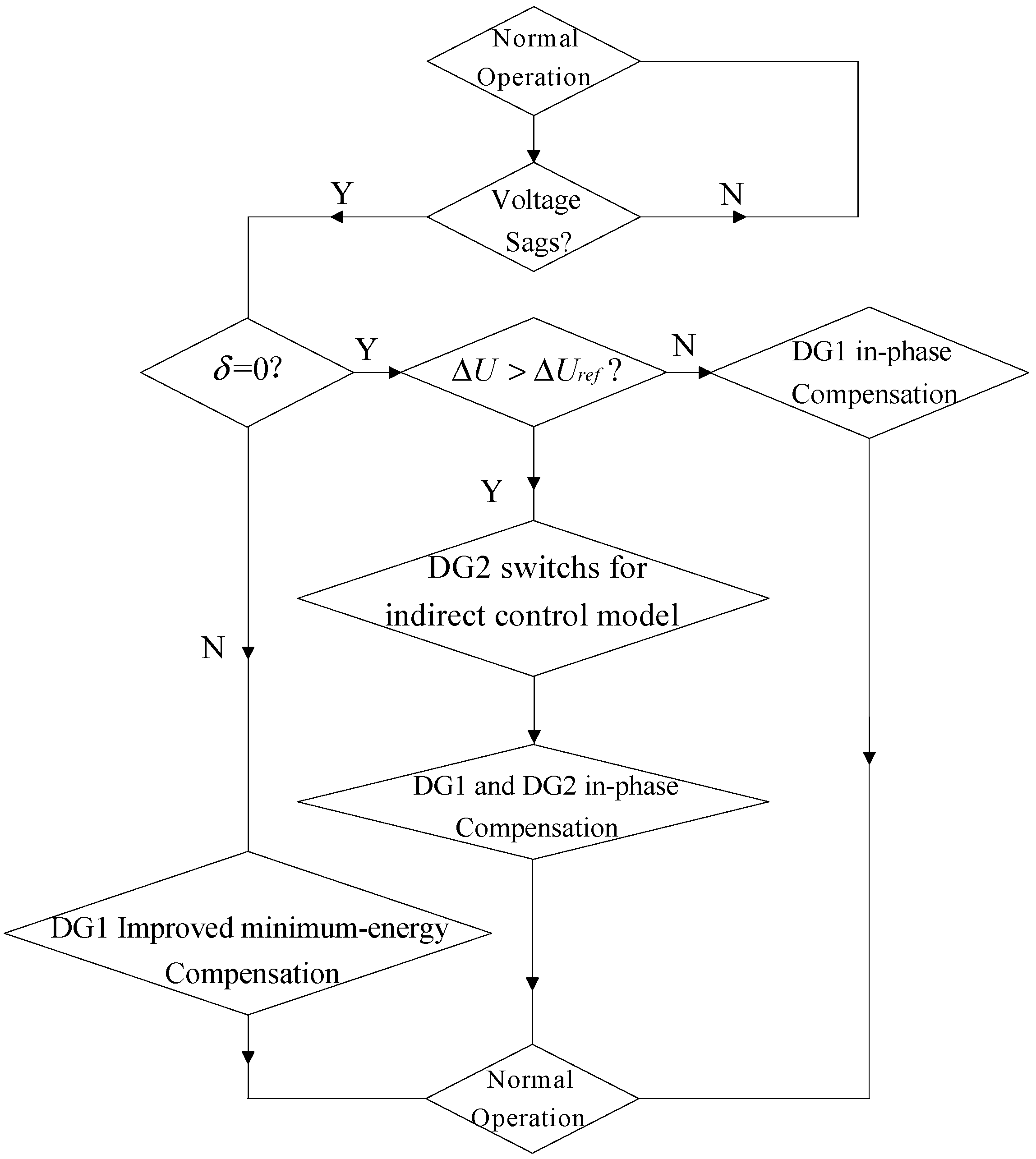
4.2.1. The Improved Indirect Control Strategy

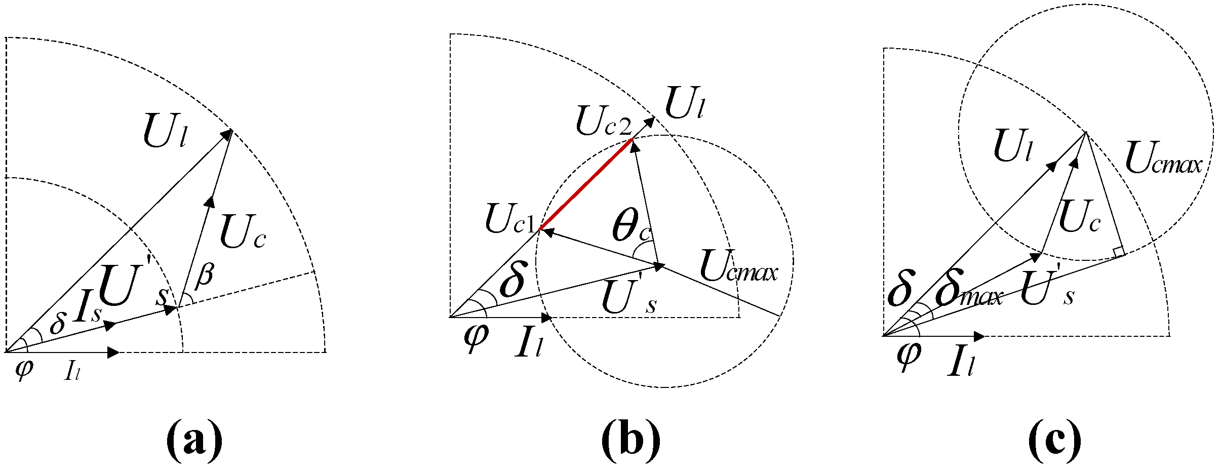
4.2.2. Comparison between Conventional Minimum-Energy and Improved Minimum-Energy Compensation
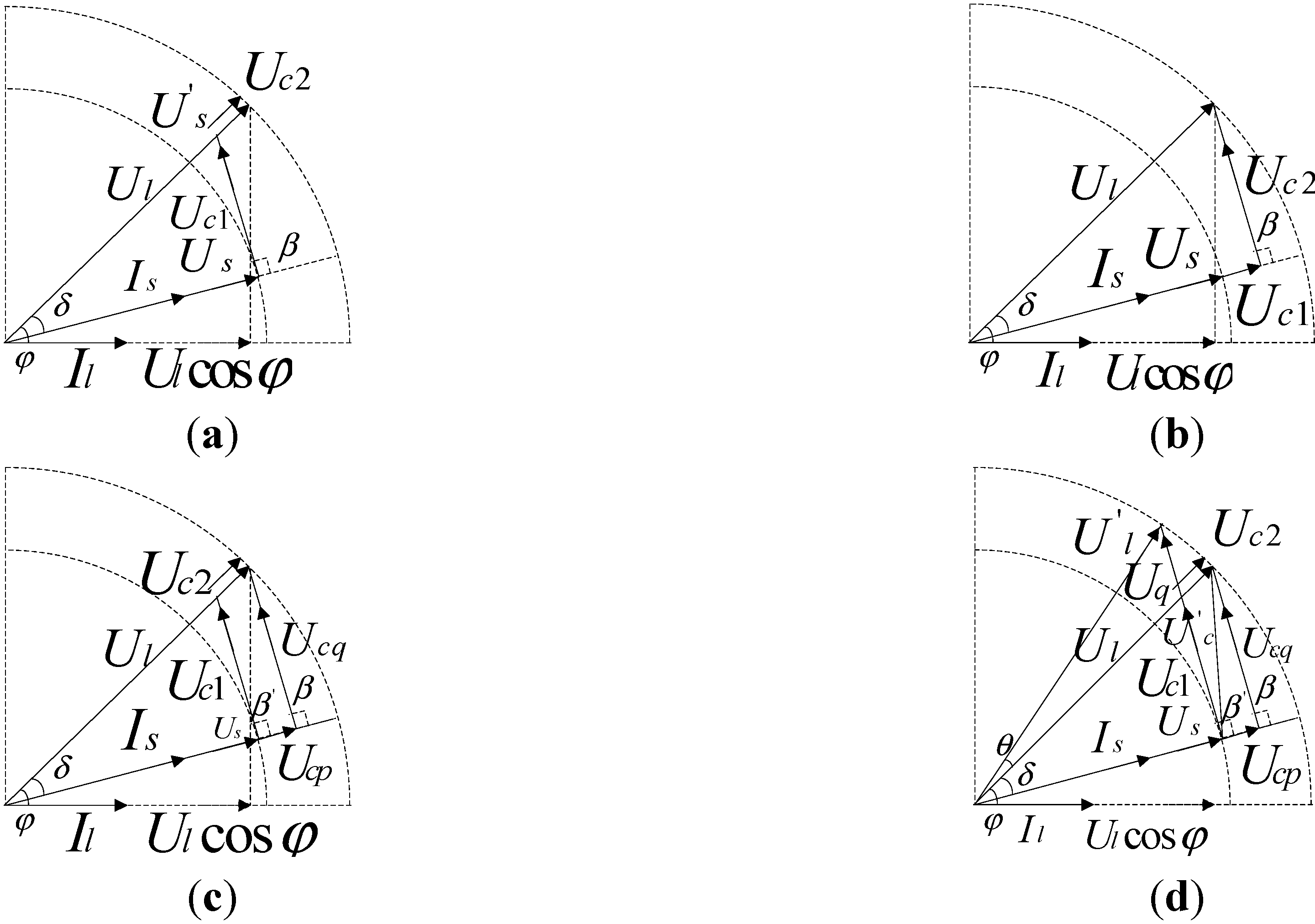
 can be obtained and its apparent power is
  . As shown in the figure, Uq > U'c, which means Sc > S'c. After comparison between this method and the conventional minimum-energy compensation method, although the active power ΔP = IsUcp increases, the apparent power S'c decreases. Specifically, the load voltage has no phase angle θ change, which is of vital importance to the protection of a load that is rather sensitive to phase jump. In combination with Figure 4, the coordination control of DG1 and DG2 can enlarge the compensation range of the voltage sag, decrease the DG capacity and decrease the power level of the converter. Its cost drops compared with the architecture in Figure 6 in paper [7].
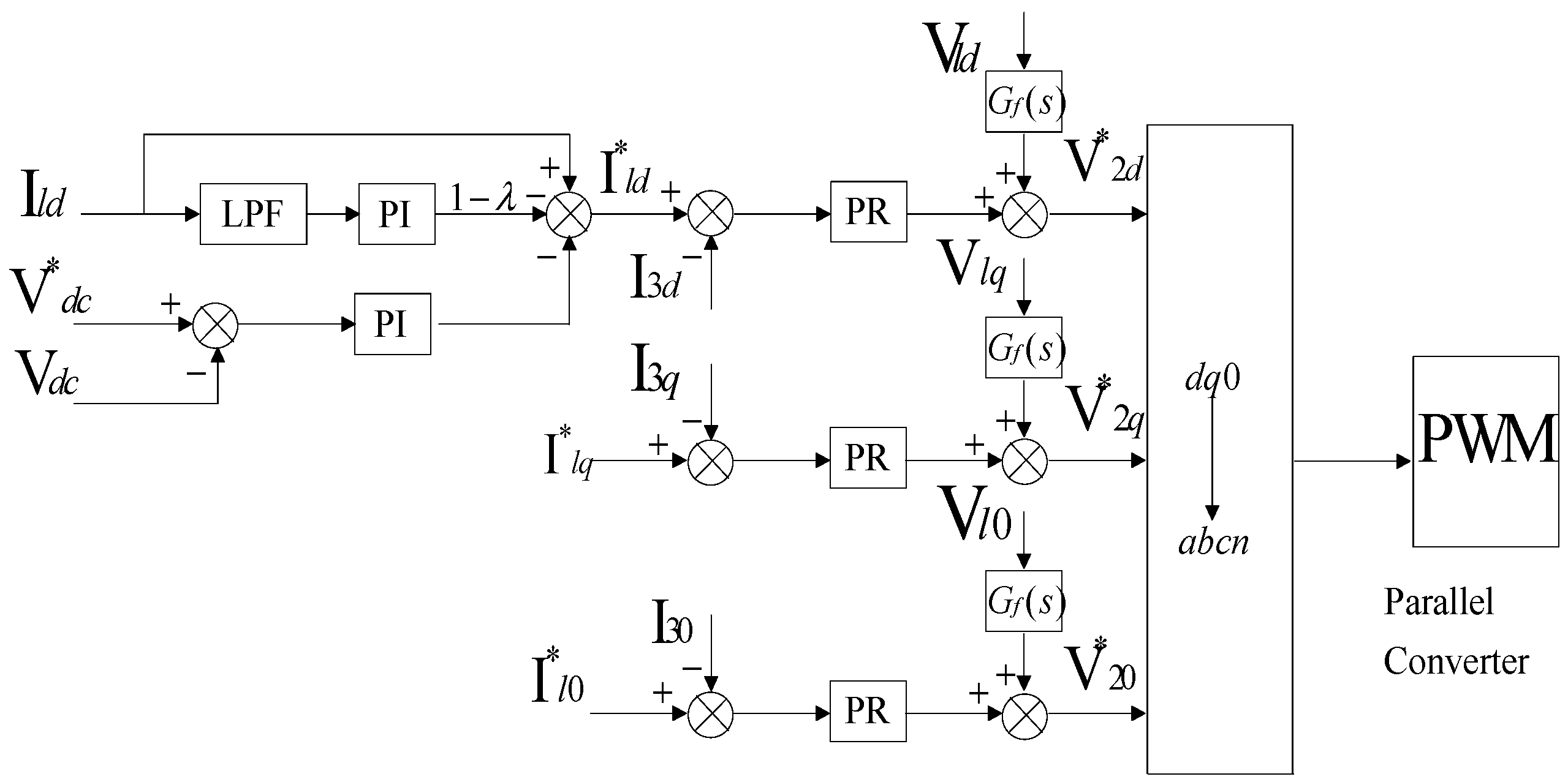
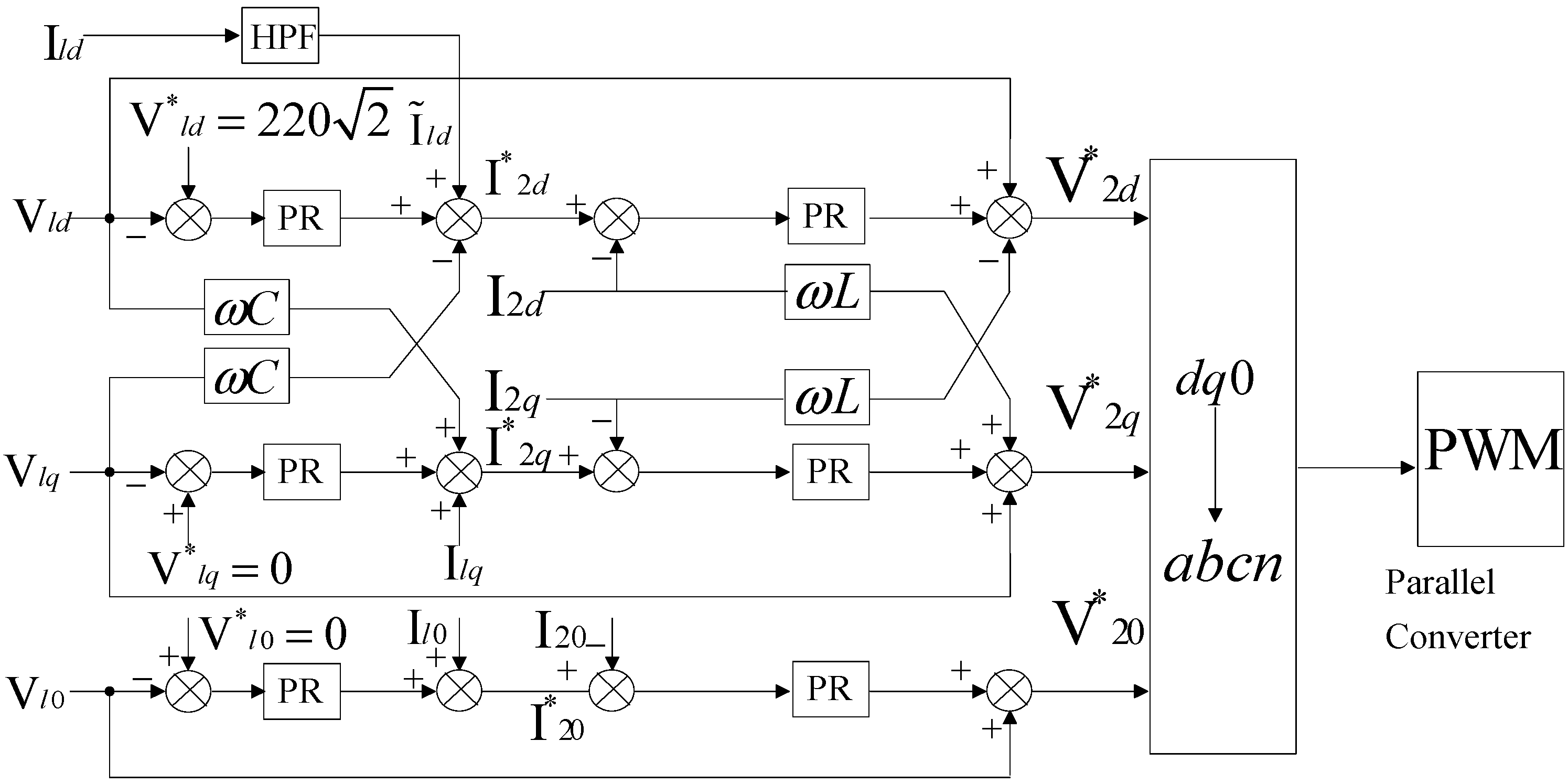
4.3. Control of a Parallel Converter


5. The Improved Direct Control Strategy Based on an Improved Structure of the UPQC
5.1. The Improved Direct Control Strategy


5.2. The Comparison between Improved Indirect Control and Improved Direct Control Strategies

| Control strategies | Improved indirect control strategy | Improved direct control strategy |
|---|---|---|
| Advantages | In voltage and current compensation, the amplitude of the required DG voltage is smaller; targeted at the voltage sag with the phase jump for a long time whose compensation effect is better; the effect of compensating harmonic current is better. | Without detection for the fault and the harmonic quantity; in voltage and current compensation, the external interference has little impact on control parameters; the applied micro-grid switching from the connected mode to islanded mode, DG2 control mode needs not to switch, and does not rely on DG1 control mode. |
| Disadvantages | In voltage and current compensation, the control parameter is rather sensitive to the external interference; compensation for voltage sags, voltage swells and the harmonic current, this method consumes more energy compared with the latter. The effective utilization rate of DG is relatively lower. | The ability of the compensating load harmonic current is little better, especially when the PCC has voltage distortion; when resolving the problem of voltage sags with a phase jump for a long time whose compensation effect is little better compared with the former. |
| Application fields | Small-power DG | Large-power DG |
6. The Simulation Verification and Analysis
| Parameter | Symbol | Value |
|---|---|---|
| Rated grid voltage | Vsabc / f | 220 V/50 Hz |
| Filter inductance | Ls / Lp | 2 mH/2 mH (ESR 0.01 Ω) |
| Filter capacitor | Cs / Cp | 100 μF/0.5 μF |
| Series transformer | N | 1:1 |
| DG voltage | Vdc | 790 V |
| DG-link capacitor | C | 4800 μF |
| Switching frequency | fsw | 10 KHz |
| Rectifier impedance | Zrec | 10 + 4 j(Ω before 0.12 s)/5 + 2 j(Ω after 0.12 s) |

| Time/Fractions | λ2P/DG2 | λ'2P/Utility grid |
|---|---|---|
| 0< t <0.12 | 0 | 1 |
| 0.12< t <0.24 | 0.15 | 0.85 |
| 0.24< t <0.34 | 0.3 | 0.7 |

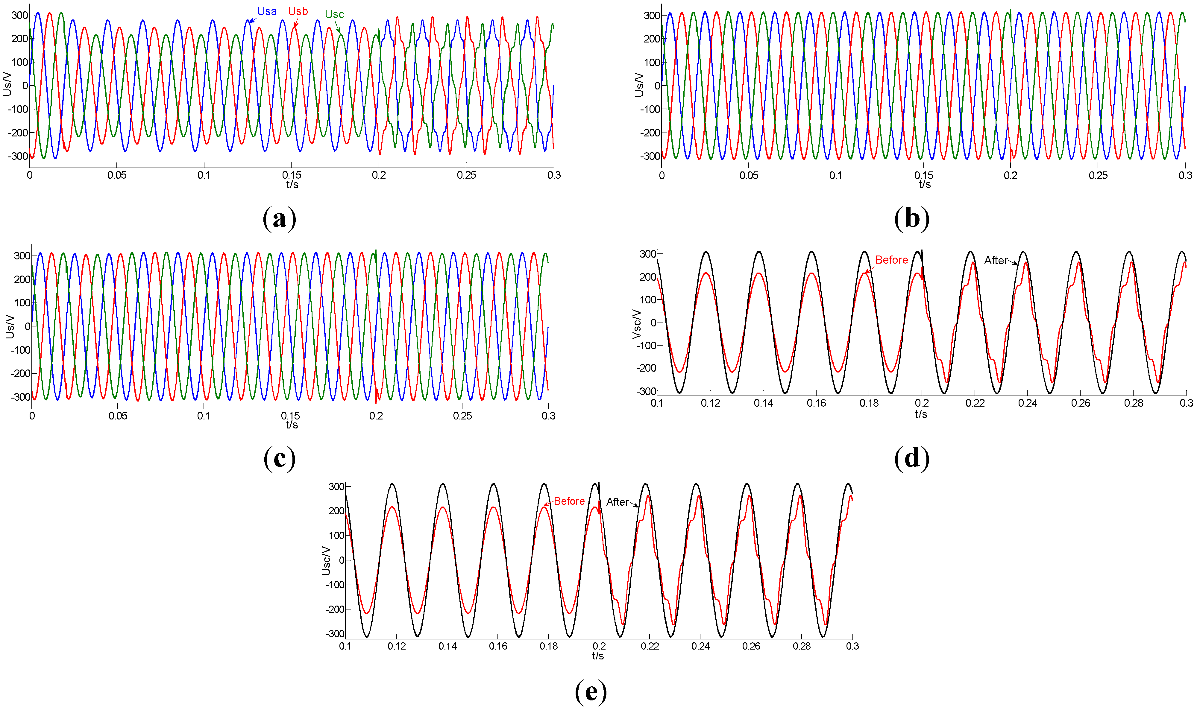
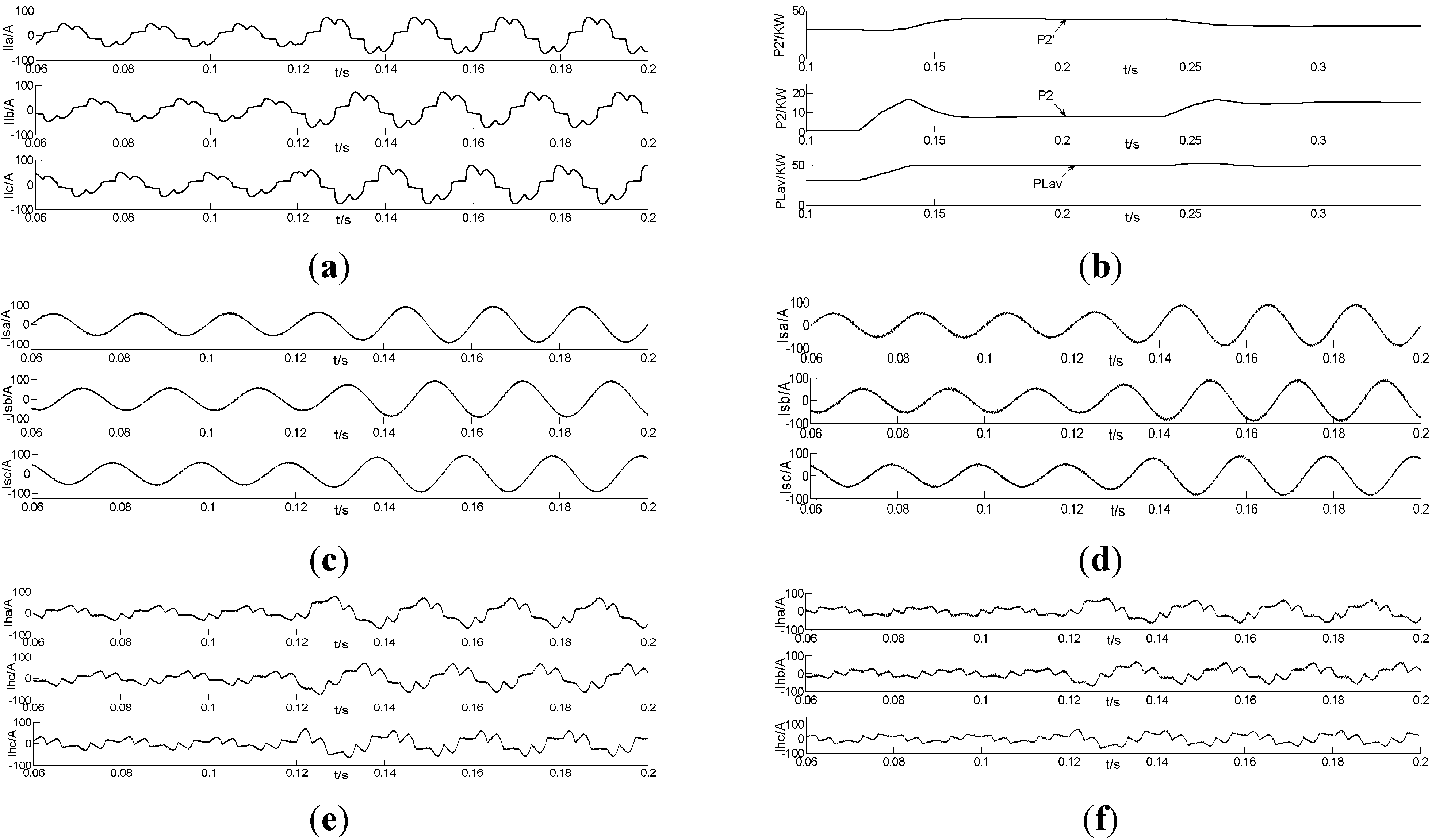
| Effect Compensation | THD of Phase a Voltage/(%) | THD of Phase b Voltage/(%) | THD of Phase c Voltage/(%) | THD of Phase a Current/(%) | THD of Phase b Current/(%) | THD of Phase c Current/(%) | Degree of unbalanced voltage/(%) |
|---|---|---|---|---|---|---|---|
| Before Compensation | 14.14 (after 0.2 s) | 14.14 (after 0.2 s) | 14.14 (after 0.2 s) | 13.61 | 15.45 | 17.37 | 5.79 |
| Indirect Control | 0.30 | 0.33 | 0.37 | 2.76 | 3.69 | 3.30 | 0.32 |
| Direct Control | 0.21 | 0.25 | 0.21 | 2.93 | 3.72 | 3.77 | 0.18 |

| Compensation methods | The actual jumped angle after compensation/(°) | The ideal jumped angle after compensation/(°) |
|---|---|---|
| Improved indirect method | 0.6353 | 0 |
| Improved direct method | 0.5906 | 0 |
| Conventional method | 22.3783 | 23.1301 |
7. Conclusions
Acknowledgments
Conflicts of Interest
References
- Marnay, C. Micro-Grids and Heterogeneous Security, Quality, Reliability, and Availability. In Proceedings of Power Conversion Conference, Nagoya, Japan, 2‑5 April 2007; pp. 629–634.
- Li, Y.W.; Vilathgamuwa, D.M.; Loh, P.C. A grid-interfacing power quality compensator for three-phase three-wire micro-grid applications. IEEE Trans. Power Electron. 2006, 21, 1021–1031. [Google Scholar] [CrossRef]
- Li, Y.W.; Vilathgamuwa, D.M.; Loh, P.C. Micro-grid power quality enhancement using a three-phase four-wire grid-interfacing compensator. IEEE Trans. Ind. Appl. 2005, 41, 1707–1719. [Google Scholar] [CrossRef]
- Majumder, R.; Ghosh, A.; Ledwich, G.; Zare, F. Load sharing and power quality enhanced operation of a distributed micro-grid. IET Renew. Power Gener. 2009, 3, 109–119. [Google Scholar] [CrossRef] [Green Version]
- Shahnia, F.; Majumder, R.; Ghosh, A. Operation and control of a hybrid micro-grid containing unbalanced and nonlinear loads. IEEE Trans. Electr. Power Syst. Res. 2010, 80, 954–965. [Google Scholar] [CrossRef] [Green Version]
- Wang, F.; Duarte, J.L.; Hendrix, M. Control of Grid-Interfacing Inverters with Integrated Voltage Unbalance Correction. In Proceedings of IEEE Power Electronics Specialists Conference, Rhodes, Greece, 15‑19 January 2008; pp. 310–316.
- Wang, F.; Duarte, J.; Hendrix, M. Grid-interfacing converter systems with enhanced voltage quality for micro-grid application—Concept and implementation. IEEE Trans. Power Electron. 2011, 26, 3501–3513. [Google Scholar]
- Shen, G.Q.; Xu, D.H.; Cao, L.P.; Zhu, X.C. An improved control strategy for grid-connected voltage source inverters with an LCL filter. IEEE Trans. Power Electron. 2008, 23, 1899–1906. [Google Scholar] [CrossRef]
- Papadimitriou, C.N.; Vovos, N.A. Transient response improvement of microgrids exploiting the inertia of a doubly-fed induction generator (DFIG). Energies 2010, 3, 1049–1066. [Google Scholar] [CrossRef]
- Zamani, M.; Yazdani, A.; Sidhu, T. A control strategy for enhanced operation of inverter-based micro-grids under transient disturbances and network faults. IEEE Trans. Power Deliv. 2012, 27, 1737–1747. [Google Scholar]
- Majumder, R.; Ghosh, A.; Ledwich, G. Power management and power flow control with back-to-back converters in a utility connected micro-grid. IEEE Trans. Power Syst. 2010, 25, 821–834. [Google Scholar] [CrossRef] [Green Version]
- Shi, X.L.; Jiang, J.C.; Guo, X.T. An efficiency-optimized isolated bidirectional dc-dc converter with extended power range for energy storage systems in microgrids. Energies 2013, 6, 27–44. [Google Scholar] [CrossRef]
- Zhang, N.; Gu, W.; Yu, H.J.; Liu, W. Application of coordinated SOFC and SMES robust control for stabilizing tie-line power. Energies 2013, 6, 1902–1917. [Google Scholar] [CrossRef]
- Xiao, Z.; Li, T.H.; Huang, M.; Shi, J.H.; Yang, J.J.; Yu, J.; Wu, W. Hierarchical MAS based control strategy for micro-grid. Energies 2010, 3, 1622–1638. [Google Scholar] [CrossRef]
- Katiraei, F.; Iravani, M.R.; Lehn, P.W. Micro-grid autonomous operation during and subsequent to islanding process. IEEE Trans. Power Deliv. 2004, 20, 248–257. [Google Scholar] [CrossRef]
- Zhang, G.R.; Zhang, T.L.; Ding, M.; Su, J.H.; Wang, H.N.; Lv, S.X.; Chen, J.L.; Xu, H.L. Simulation research on unified power quality conditioner with PV grid connected generation. Proc. CSEE 2007, 27, 82–86. [Google Scholar]
- Hsn, B.; Bae, B.; Kim, H.; Baek, S. Combined operation of unified power-quality conditioner with distributed generation. IEEE Trans. Power Deliv. 2006, 21, 330–338. [Google Scholar]
- Cai, L.H.; Jing, P.; Wu, S.Y.; Li, H.X. Control strategies of dynamic voltage restorer. Electr. Power Automot. Equip. 2007, 27, 22–25. [Google Scholar]
- Vilathgamuwa, D.M.; Perera, A.A.D.R.; Choi, S.S. Voltage sag compensation with energy optimized dynamic voltage restorer. IEEE Trans. Power Deliv. 2003, 18, 928–936. [Google Scholar] [CrossRef]
- Choi, S.S.; Li, B.H.; Vilathgamuwa, D.M. Dynamic voltage restoration with minimum energy injection. IEEE Trans. Power Syst. 2000, 51–57. [Google Scholar] [CrossRef]
- Wang, F.; Duarte, J.; Hendrix, M. Pliant active and reactive power control for grid-interactive converters under unbalanced voltage dips. IEEE Trans. Power Electron. 2011, 26, 1511–1521. [Google Scholar] [CrossRef]
- Zhou, N.C.; Chi, Y.; Wang, Q.G. Control strategies for micro-grid containing non-linear and unbalanced loads. Autom. Electr. Power Syst. 2011, 35, 61–66. [Google Scholar]
- Mohammad, D.; Amirnaser, Y. Islanded-mode control of electronically coupled distributed-resource units under unbalanced and nonlinear load conditions. IEEE Trans. Power Deliv. 2011, 26, 661–673. [Google Scholar]
© 2013 by the authors; licensee MDPI, Basel, Switzerland. This article is an open access article distributed under the terms and conditions of the Creative Commons Attribution license (http://creativecommons.org/licenses/by/3.0/).
Share and Cite
Xia, M.; Li, X. Design and Implementation of a High Quality Power Supply Scheme for Distributed Generation in a Micro-Grid. Energies 2013, 6, 4924-4944. https://doi.org/10.3390/en6094924
Xia M, Li X. Design and Implementation of a High Quality Power Supply Scheme for Distributed Generation in a Micro-Grid. Energies. 2013; 6(9):4924-4944. https://doi.org/10.3390/en6094924
Chicago/Turabian StyleXia, Mingchao, and Xiaoliang Li. 2013. "Design and Implementation of a High Quality Power Supply Scheme for Distributed Generation in a Micro-Grid" Energies 6, no. 9: 4924-4944. https://doi.org/10.3390/en6094924