
A study on demagnetization heat treatment of waste neodymium iron boron (NdFeB) magnets by using computer simulation
- Published
- Accepted
- Received
- Academic Editor
- Junkuo Gao
- Subject Areas
- Electronic, Optical and Magnetic, Materials Science (other)
- Keywords
- Demagnetization, NdFeB, Heat treatment, Computer simulation, Magnetic flux
- Copyright
- © 2023 Kim et al.
- Licence
- This is an open access article distributed under the terms of the Creative Commons Attribution License, which permits unrestricted use, distribution, reproduction and adaptation in any medium and for any purpose provided that it is properly attributed. For attribution, the original author(s), title, publication source (PeerJ Materials Science) and either DOI or URL of the article must be cited.
- Cite this article
- 2023. A study on demagnetization heat treatment of waste neodymium iron boron (NdFeB) magnets by using computer simulation. PeerJ Materials Science 5:e28 https://doi.org/10.7717/peerj-matsci.28
Abstract
In this study, demagnetization heat treatment at 100 ∼400 °C is studied by using computer simulation to secure the optimal demagnetization heat treatment conditions for waste neodymium iron boron (NdFeB) permanent magnets. From the computer simulation, the temperature of the magnet during heat treatment is higher than the set temperature by up to 6 °C. Delay time occurs when the furnace internal temperature and magnet temperature reached the set temperature. A delay time of 15 minutes in an air atmosphere and 10 minutes in a nitrogen atmosphere occurs. The Nd magnet was completely demagnetized at 300 °C as the magnetic flux decreased when the heat treatment temperature increased up to 250 °C. The fully demagnetized magnet could be magnetized to the level of a new magnet. It was confirmed that NdFeB magnets heat treated up to 350 °C in a nitrogen atmosphere can be reusable due to stable demagnetization being possible without surface change.
Introduction
Neodymium iron boron (NdFeB) magnets (hereafter referred to as NdFeBM) have strong magnetic properties, making suitable not only for industries requiring large amounts of energy, such as electric vehicle motors, wind power generation motors, large home appliances, and magnetic resonance imaging devices, but also for lightweight and miniaturized IT products, such as speakers. It is also widely used in small electronic devices such as headphones and computers.
However, rare earth elements are only found in some countries. Supply is unstable because it is mined and produced in only a few countries, and many countries rely solely on imports. For this reason, various studies are being conducted for the stable supply and demand of rare earth resources. Neodymium (Nd) can be replaced with cheaper rare earth such as La and Ce (Ren et al., 2018; Zhang et al., 2019; Jin et al., 2018). A technology that can completely replace rare earth elements, such as Fe-N and Fe-Ni magnets is being researched (Li et al., 2016; Ogi et al., 2013; Lewis et al., 2014; Kotsugi et al., 2011). In addition, technologies for recovering NdFeBM from large home appliances or vehicles that are discarded after use and recycling them through chemical processes or reusing the magnets as they are being researched (Kim et al., 2022; Jeon et al., 2018; Ahn et al., 2017; Li et al., 2019).
NdFeBM must first be demagnetized before being reused. NdFeBM are generally known to have a Curie temperature of 312 °C, which varies between 300 °C and 350 °C depending on the composition of the rare earth (Cha et al., 2019).
When a temperature higher than the Curie temperature is applied, demagnetization occurs, when magnetism is lost. NdFeBM have strong magnetism. Therefore, when collecting waste magnets, if the magnets are attached to the equipment, it is very difficult to separate and handle them. To prevent this, magnetism is removed through heat treatment.
However, when demagnetizing using heat treatment in an air atmosphere, NdFeBM are easily oxidized. In an overseas study, the research result states that the oxidation reaction of NdFeBM starts around 300 °C (Firdaus et al., 2018).
As oxidation proceeds around the Curie temperature, precise temperature control of the NdFeBM during demagnetization heat treatment is essential for reuse. A method of heat treatment in a non-oxidizing atmosphere involves an inert gas suppressing the oxidation of a magnet during the demagnetization process. Examples of inert gases include Ar, N2, and He, with N2, being the most inexpensive and widely used.
Therefore, accurate temperature control of the NdFeBM is required in a demagnetization heat treatment environment such as an air and nitrogen atmosphere.
In this study, the thermal history of NdFeBM is confirmed through computer simulation of air and nitrogen atmosphere to establish demagnetization heat treatment conditions, and furthermore, confirm the reusability of NdFeBM.
Materials & Methods
Specimens and analysis
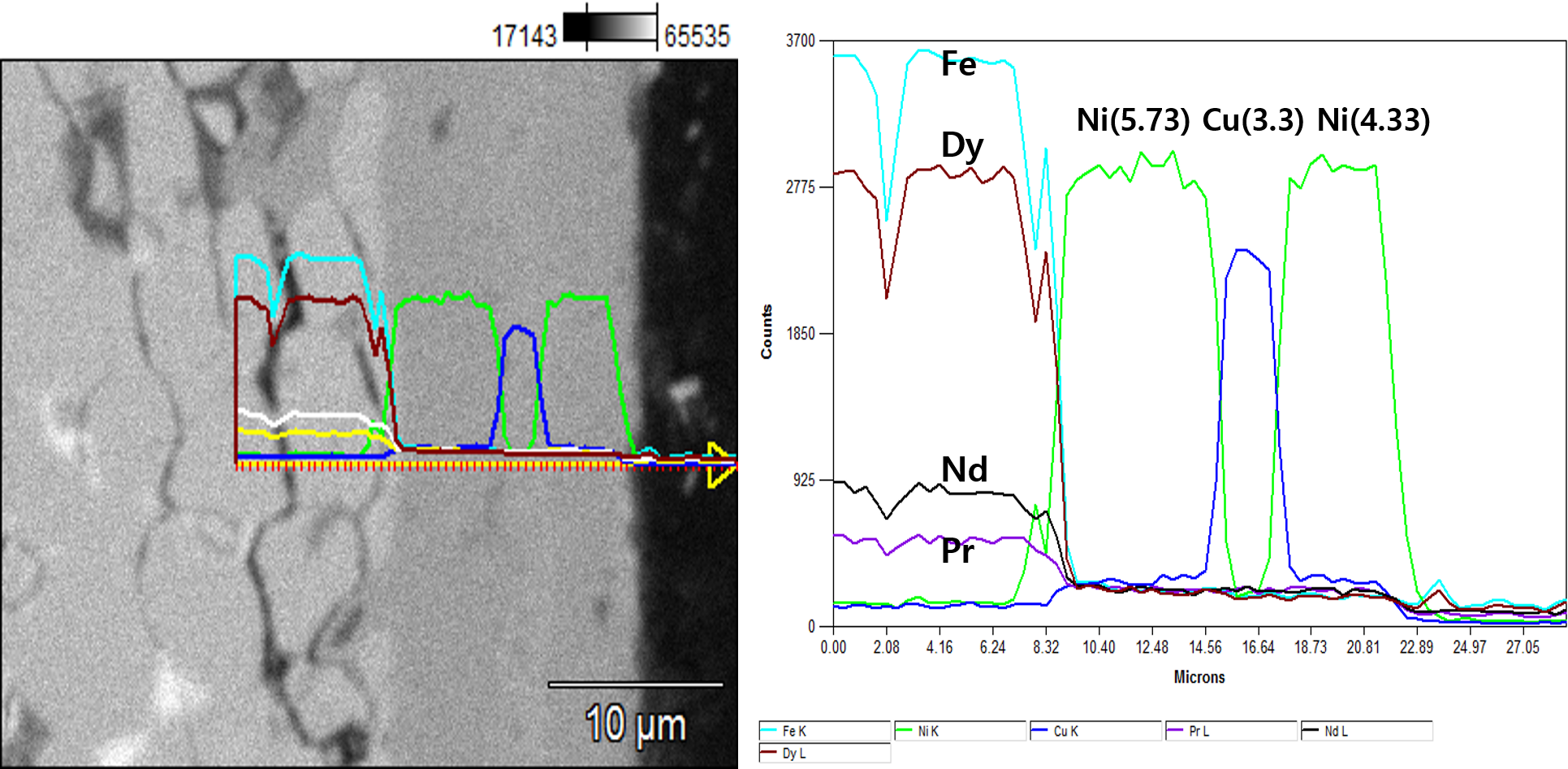
The NdFeBM used in the experiment is a N48H magnet. The specifications are 20 mm in diameter and 10 mm in height of a disc shape. The NdFeBM was analyzed using an optical microscope, high-resolution scanning electron microscope (HRFESEM) model SU8010, and an energy dispersive X-ray spectrometer (EDS) to confirm the integrity of the surface plating layer after demagnetization. Table 1 is the result of analyzing the composition ratio of the NdFeBM by EDS. Since it is a high-temperature Nd magnet of H grade, it contains 1% of Dy. Figure 1 is the result of analyzing the boundary between the base material of the magnet and the plating layer with line profiles to analyze the components, structure, and thickness of the plating layer that protects the surface of the magnet. The plating layer was composed of a 3-layer structure of Ni/Cu/Ni and was found to have a thickness of about 13 µm.
Heat treatment equipment
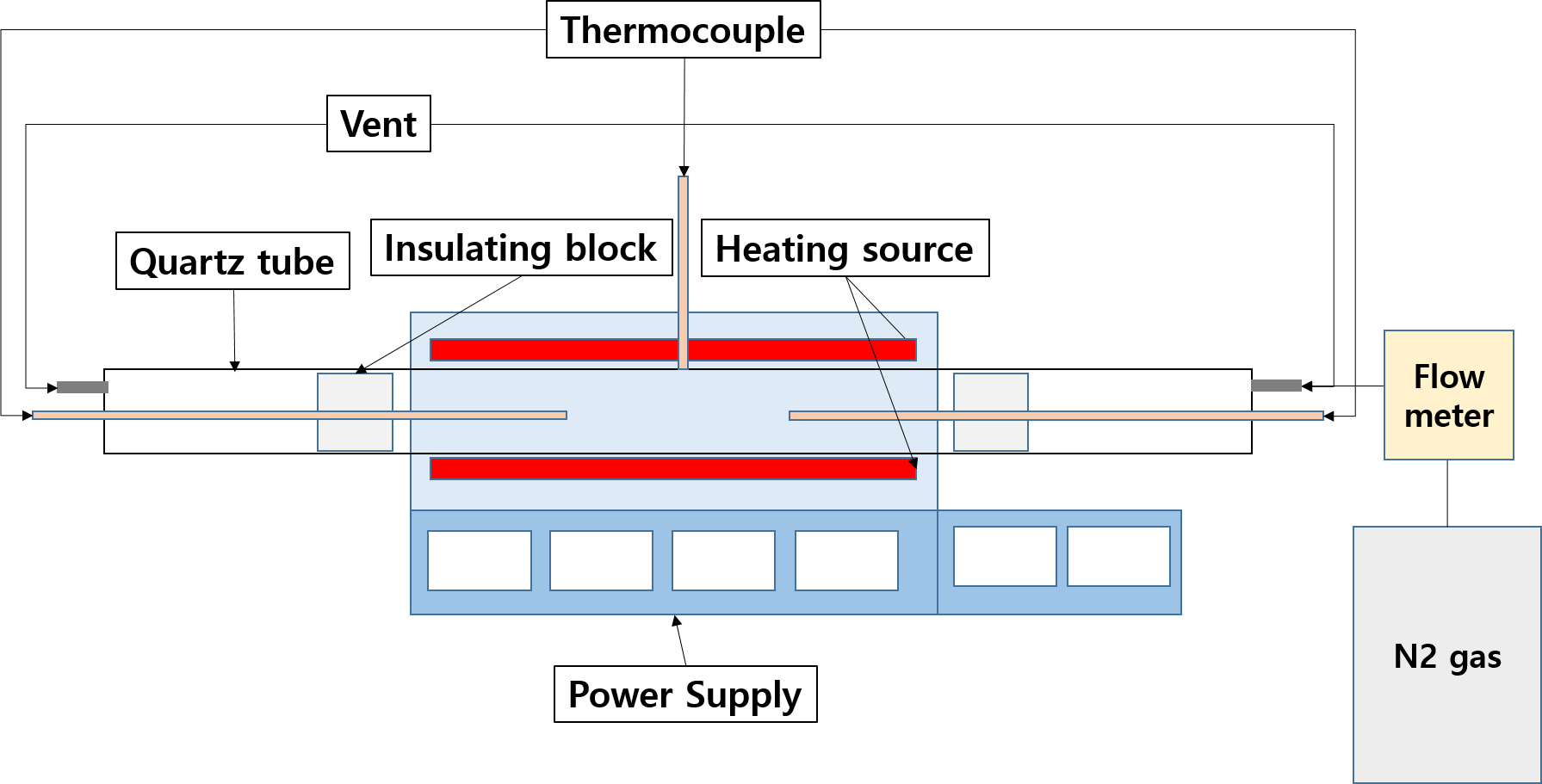
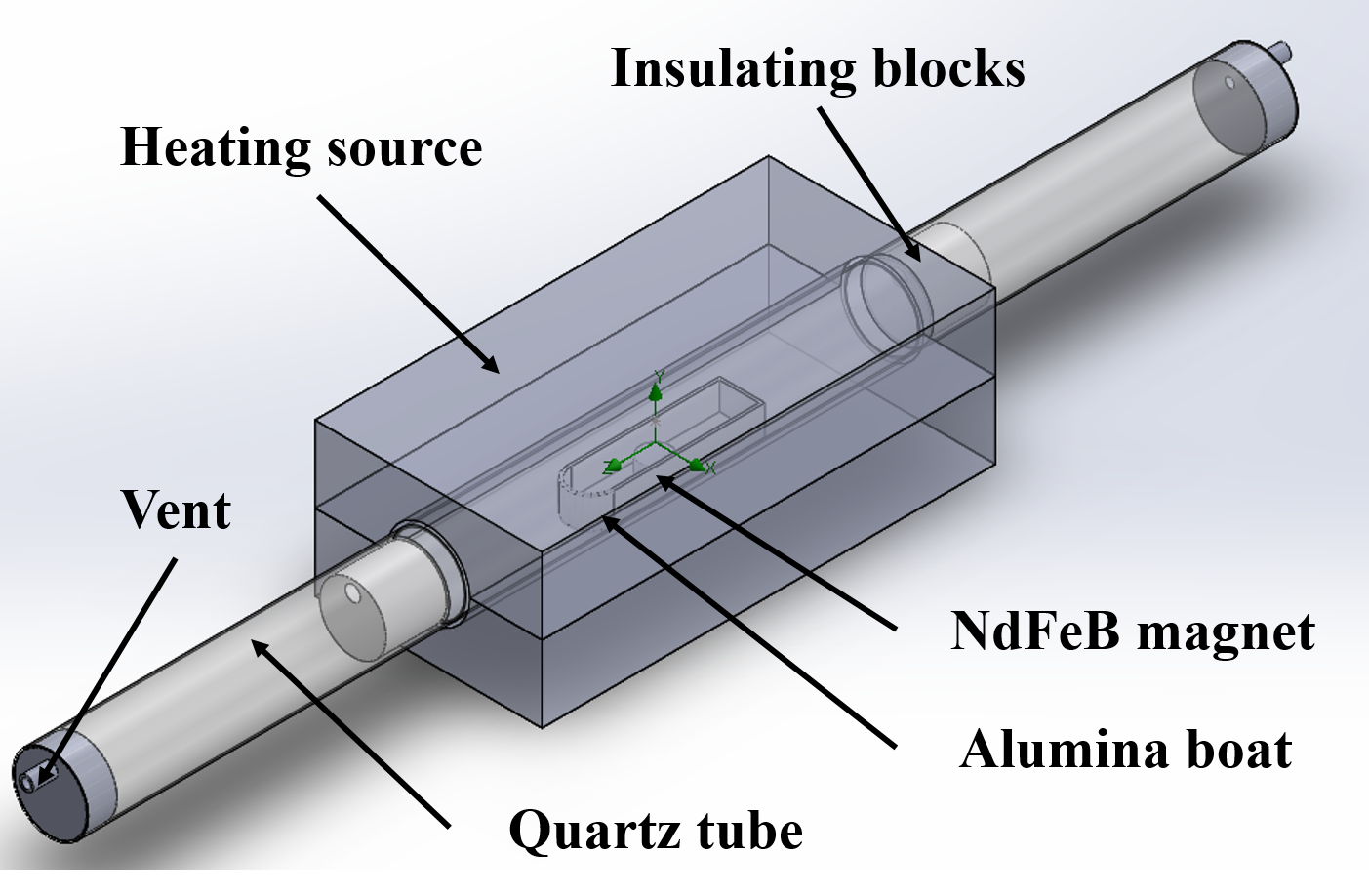
To demagnetize the NdFeBM, heating above the Curie temperature is necessary. A quartz tube furnace was used in the experiment as shown in Fig. 2. During heat treatment in the quartz tube furnace, thermocouple sensors are placed separately on both sides of the quartz tube in addition to the temperature control sensor in the center of the furnace to accurately control the temperature. The tip of the sensor is adjusted to the center of the NdFeBM specimen. For insulation during heat treatment, a refractory block was placed in heat sink of the quartz tube, with both ends sealed with silicon stoppers. The atmosphere in the heat treatment furnace is controlled by connecting a stainless tube of four mm to a silicon stopper for that nitrogen to flow there through. The flow rate of nitrogen was controlled with a flow meter. The heat treatment was carried out in batches where in which specimens were charged and heated at room temperature, and the atmosphere in the furnace is different from air and nitrogen. Heat treatment was performed at 100 ∼ 400 °C, with the heating time calculated and the temperature raised at a rate of 8 °C / min. The heat treatment in a nitrogen atmosphere was performed by controlling the nitrogen flow rate at 2 L/min.
| Composition (wt%) | |||||
|---|---|---|---|---|---|
| Nd | Pr | Fe | O | B | Dy |
| 19.07 | 4.79 | 71.85 | 1.23 | 1.23 | 0.98 |
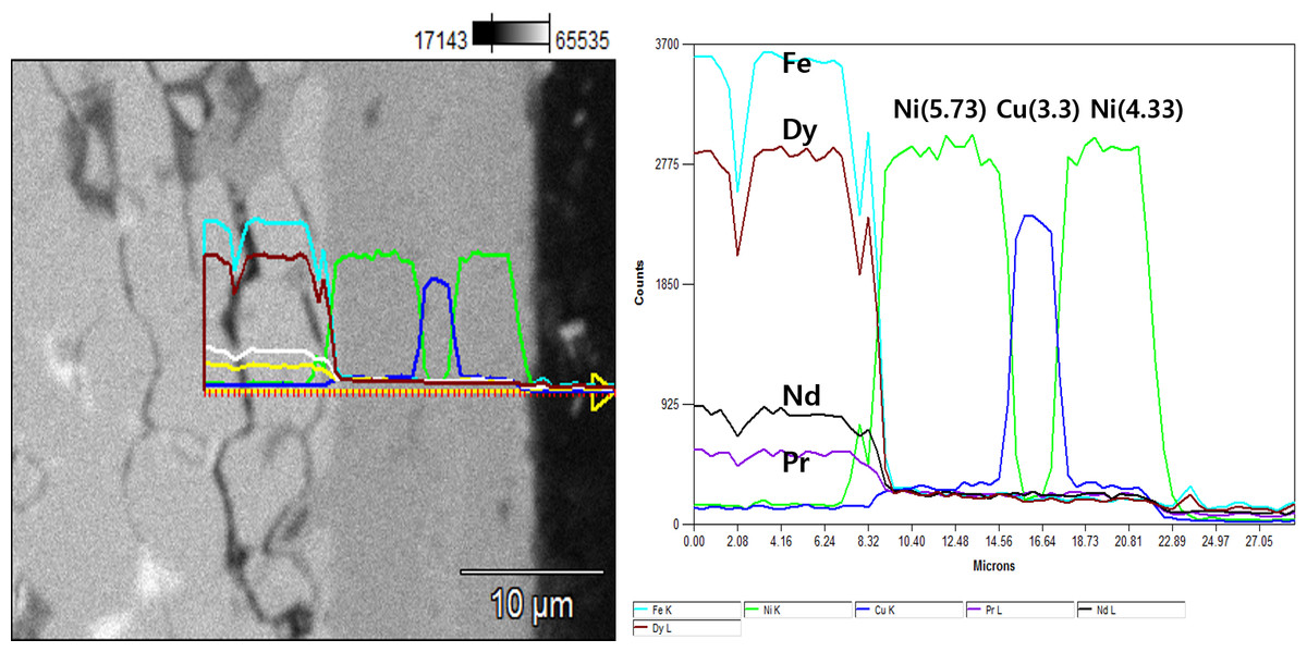
Figure 1: Cross-section of plating layer of Nd magnet.
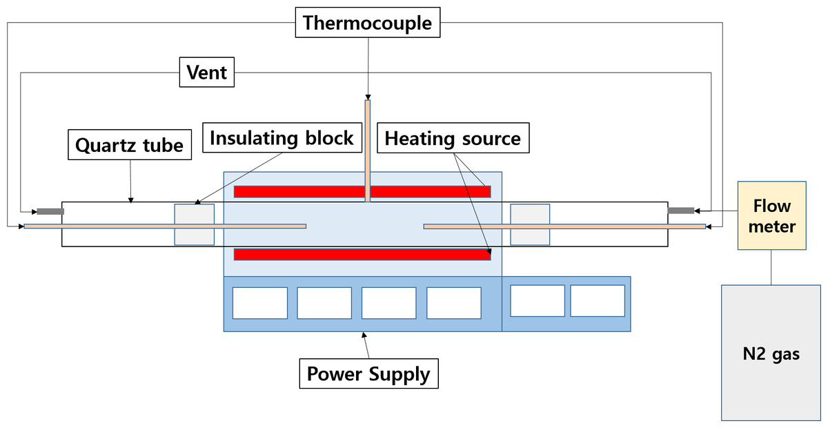
Figure 2: Quartz tube furnace.
Computer simulation of demagnetization heat treatment
For accurate demagnetization heat treatment, it is necessary to grasp the actual temperature change during heat treatment of the NdFeBM. Since the temperature inside the quartz tube is shielded by an external heat source, only the temperature around the magnet and inside the furnace can be measured using a thermocouple. Based on these measured values, the temperature of the Nd magnet inside the furnace was estimated by computer simulation with SOLIDWORKS, a thermal fluid analysis program. As of now, the governing equation used in the thermal flow analysis is as follows.
(1) Continuity equation (1)
(2) momentum equation (2)
(3) Energy equation (3)
t: time, ρ: density of the fluid, p: static pressure, τij: viscous shear stress, fi: volume force,
q: heat flux, hs : static enthalpy.
Figure 3 is the model used in the computational simulation. It was designed to mimic the quartz tube furnace, a heat treatment equipment. Table 2 shows the material and physical property values of each part of the analysis model. Starting at the initial room temperature of 20 °C, the internal temperature was raised to the set temperature of 100 ∼ 400 °C at a constant rate of 8 °C / min. The computational simulation of heat treatment in a nitrogen atmosphere limits nitrogen gas to pass through the quartz tube at a rate of 2 L/min.
Magnetic analysis of specimens
The purpose of this study is to confirm the possibility of reusing magnetized NdFeBM s after demagnetization heat treatment through conditions predicted by computer simulation heat treatment. It is necessary to check the demagnetization and magnetization, as determined by measuring the magnetic flux density of the NdFeBM. Magnetic flux density was measured using Tesla meter TM-601 equipment from Kanetec Co., Ltd. For more accurate measurement, the magnetic flux density was measured at three points at equal intervals centered on the plane perpendicular to the magnetization direction of the magnet, and the average value was defined as the measured value. For magnetization of the demagnetized NdFeBM, SCMI Co., Ltd.’s MCB-3530M capacitor discharge type magnetization power supply was used. The specifications of the device are: input voltage AC 220 V, maximum charging voltage DC 3500 V, capacitor capacity 3000 µF, maximum discharge current 40 kA, maximum discharge energy 18,375 J.
Results and Discussion
Comparison of computer simulation and heat treatment temperature
In actual heat treatment, it is known that the flux attenuation of NdFeBM is more dependent on temperature than time (Haavisto et al., 2010). For this reason, during the demagnetization heat treatment, the temperature of the NdFeBM from the heat source is paramount.
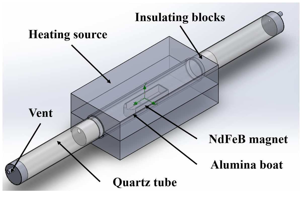
Figure 3: Computational simulation model of heat treatment in N2 gas.
| Specific heat [J/kg/k] |
Thermal conductivity [W/m/K) |
Density [kg/m3] |
|
|---|---|---|---|
| Heating source | 700 | 0.27 | 837 |
| Alumina Boat |
3960 | 30 | 850 |
| NdFeB magnet | 7800 | 9 | 440 |
| Quartz tube | 2200 | 2 | 700 |
| Insulating block | 2300 | 1.4949 | 877.96 |
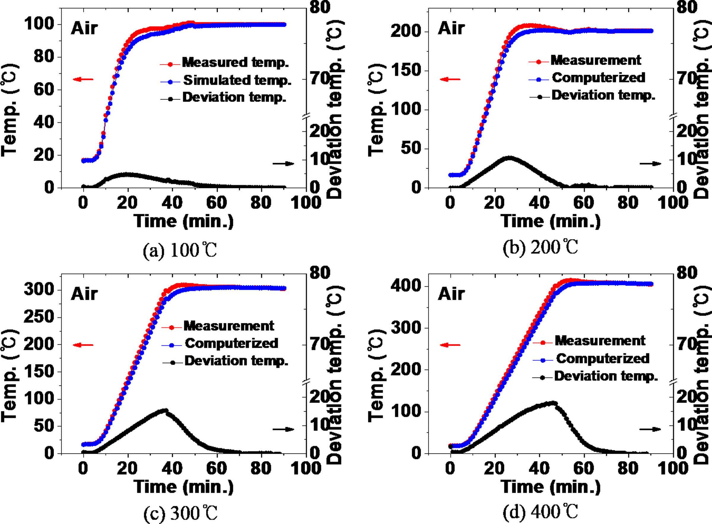
Figure 4 compares the measured value of the temperature inside the furnace and the value simulated by computer when heat treatment is performed at the range of 100 °C to 400 °C in an air atmosphere. During the heat treatment at 100 °C in Fig. 4A, a deviation occurred between the actual temperature and the simulated temperature during the temperature increase. In this logarithmical curve, temperature inside the furnace increased. In the temperature rising section, the temperature deviation increased from the beginning of the heat treatment, to a deviation of 5 °C at the 20-minute point, indicating that the actual temperature was higher. This is considered to be the result of the difference between the specific heat value of the equipment resource and the actual value in the computer simulation.
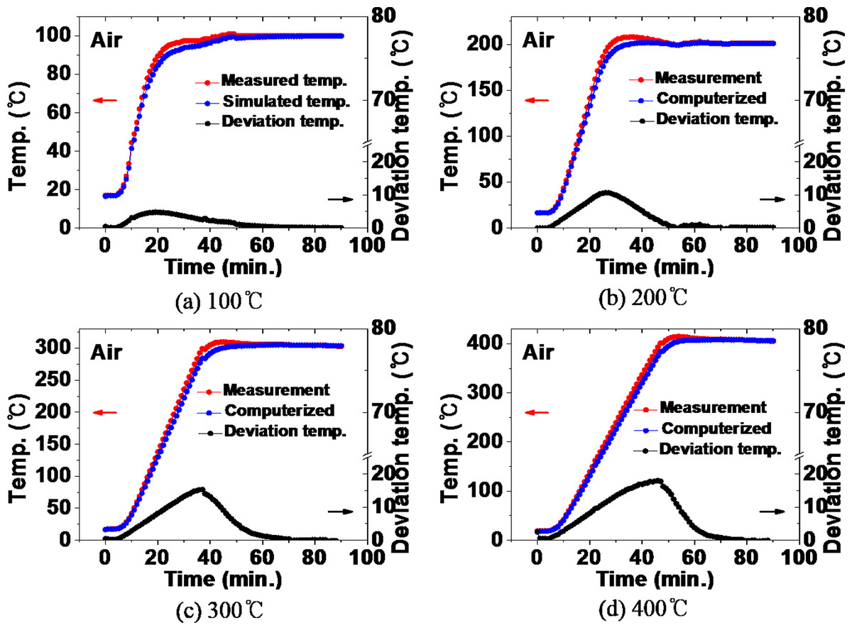
Figure 4: (A–D) Comparison between the actual measured value and the simulated value of the furnace internal temperature during heat treatment in an air atmosphere.
Subsequently, the deviation generally decreases. At 50 min the actual temperature and the simulated temperature remained the same without temperature deviation. In the case of the 200 °C heat treatment in Fig. 4B, after showing a temperature deviation of 10 °C at 26 min, the deviation decreased and a constant temperature was maintained without temperature deviation from 50 min. The same tendency was shown in the heat treatment at 300 °C and 400 °C in Figs. 4C and 4D.
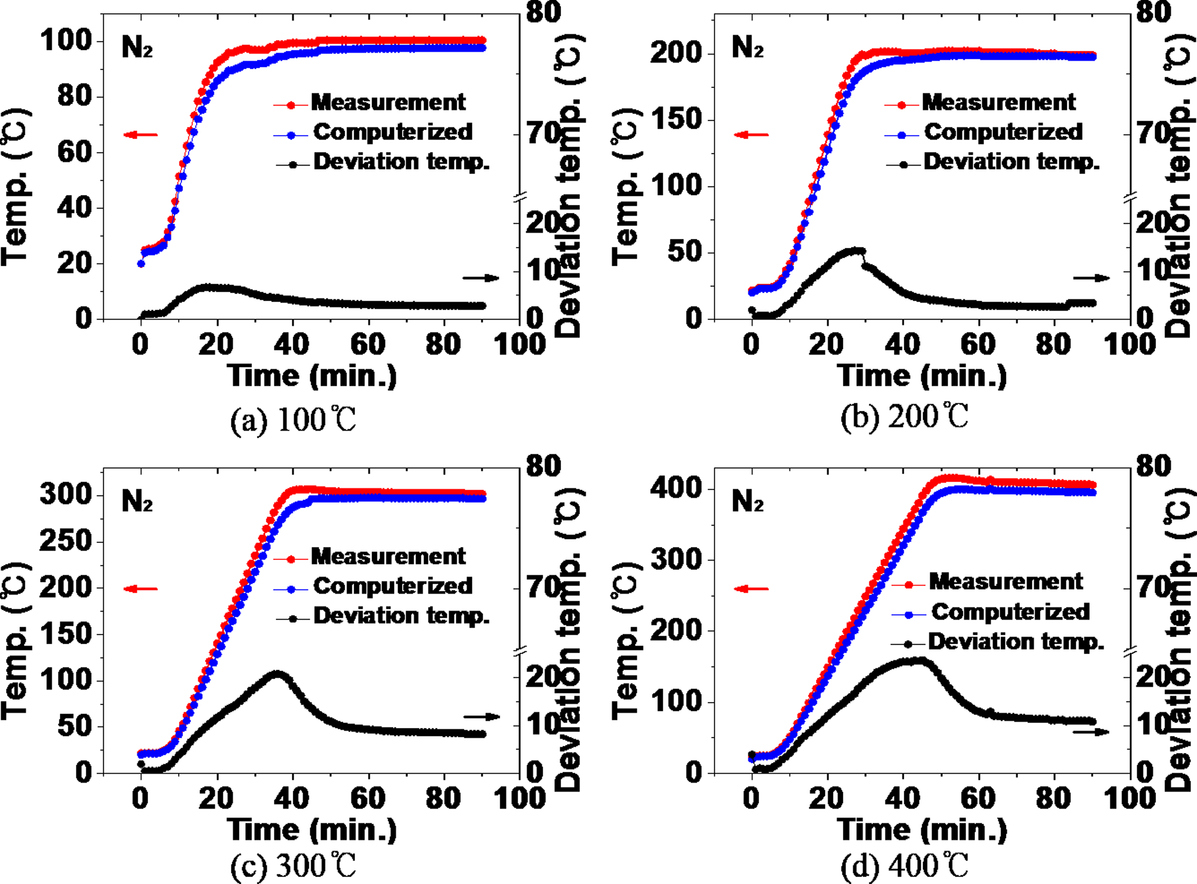
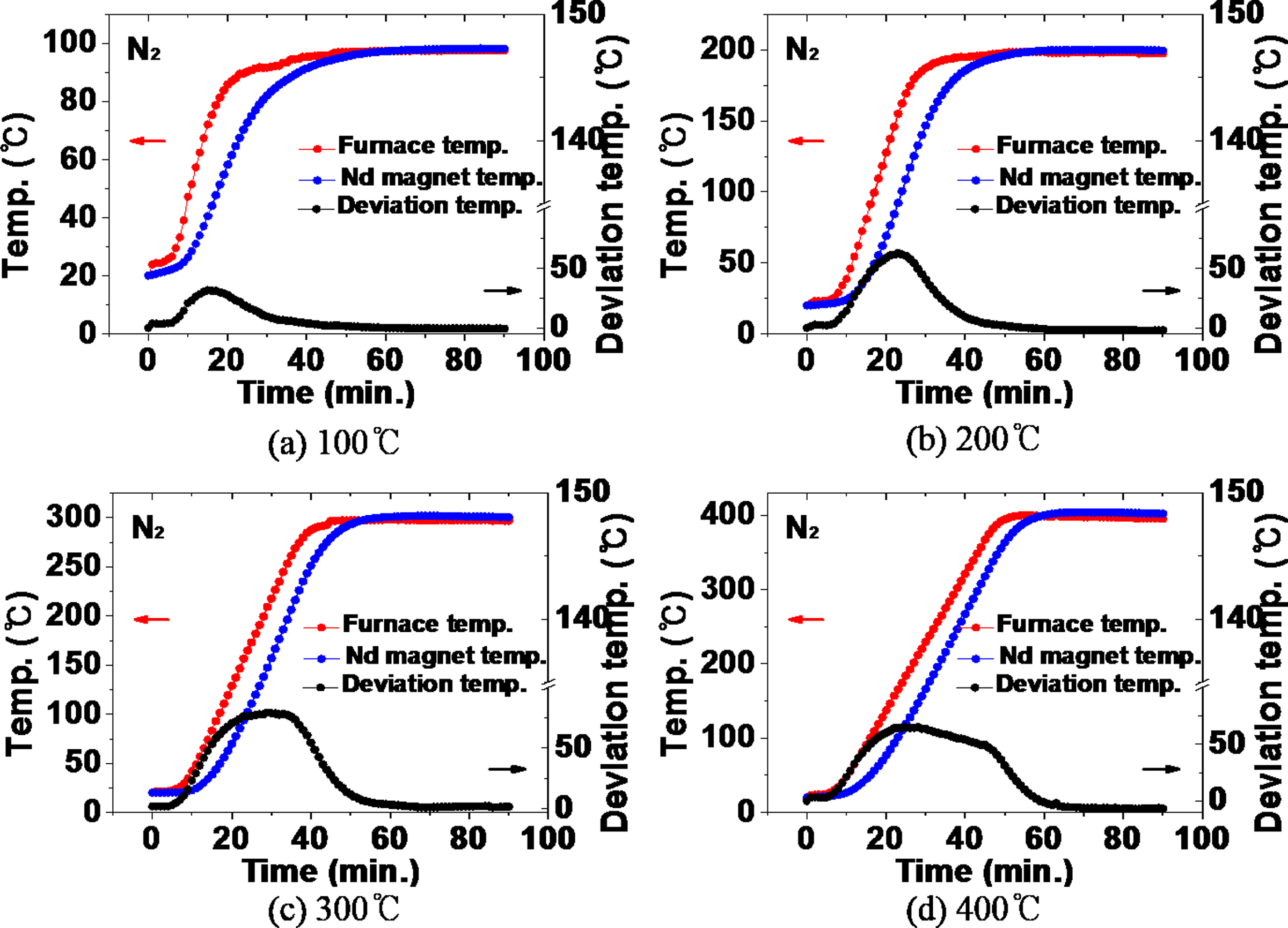
Figure 5 compares the measured value of the temperature inside the furnace and the simulated value during heat treatment in a nitrogen atmosphere. In the case of heat treatment at 100 °C in a nitrogen atmosphere in Fig. 5A, a temperature deviation of 6 °C was shown at 17 min, which slightly decreased, followed by a constant temperature deviation of about 3 °C (3% deviation) was maintained. In the 200 °C heat treatment in Fig. 5B, after showing a temperature deviation of 14 °C in 30 min, the deviation decreased and maintained a constant deviation of 3 °C (1.5% deviation). At 300 °C in Fig. 5C, a temperature deviation of 26 °C occurred at 38 min, and a constant temperature deviation of 8 °C (2.7% deviation) was maintained thereafter. At 400 °C in Fig. 5D, a constant temperature deviation of 10 °C (2.5% deviation) was maintained after a temperature deviation of 23 °C at 38 min. As the heat treatment temperature increased, the maximum deviation between the actual measured temperature and the temperature calculated by computer simulation increased together with the time for the maximum temperature deviation to occur. In the air atmosphere, the actual temperature and the simulated temperature completely matched in the temperature holding section, while the temperature deviation was less than about 3% in the nitrogen atmosphere. This is determined to be an error caused by forcibly introducing room temperature nitrogen and affecting the convection phenomenon inside the furnace. Therefore, the temperature deviation of the furnace internal temperature in the air atmosphere and the nitrogen atmosphere was less than 3%, secures the reliability of the computational simulation results.
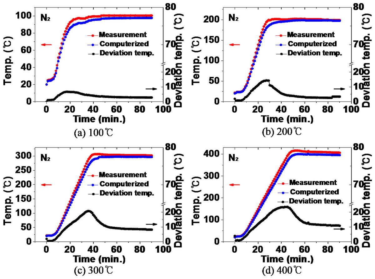
Figure 5: (A–D) Comparison between the actual measured value and the simulated value of the furnace internal temperature during heat treatment in a nitrogen atmosphere.
Thermal history behavior of NdFeBM during demagnetization heat treatment
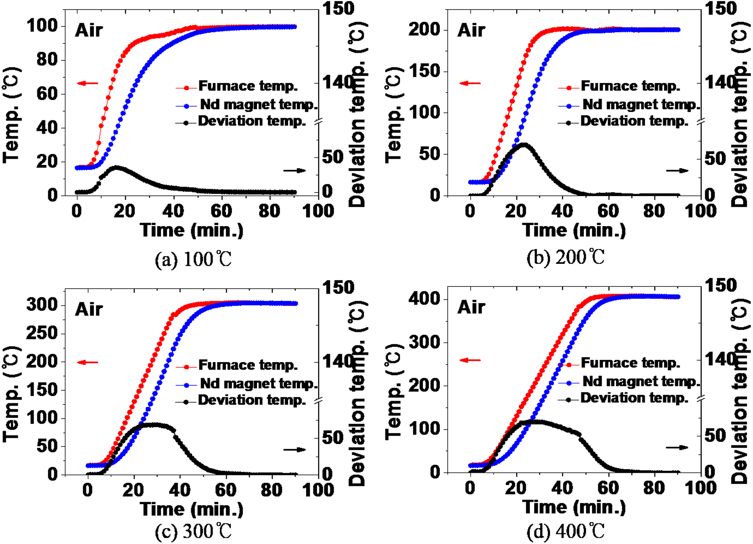
Previously, by comparing the actual internal temperature and the furnace internal temperature calculated through computer simulation, it was confirmed that the simulation result is very similar to the actual one. Based on these results, the thermal history over time of the NdFeBM during demagnetization heat treatment in the range of 100 ∼ 400 °C was calculated using computer simulation. Figure 6 shows the comparison between the temperature inside the furnace and the thermal history of the NdFeBM specimen during heat treatment in an air atmosphere. It can be seen that their difference between the temperature inside the furnace and the temperature of the NdFeBM in the temperature rising period. At 100 °C in Fig. 6A, the temperature inside the furnace rises faster than that of the NdFeBM in the heating section. During that time, a temperature deviation occurred and rose to a maximum of 35 °C in 16 min. After that, it started to decrease, and at 58 min, the final temperature of the NdFeBM and the inside of the furnace coincided with 100 °C.
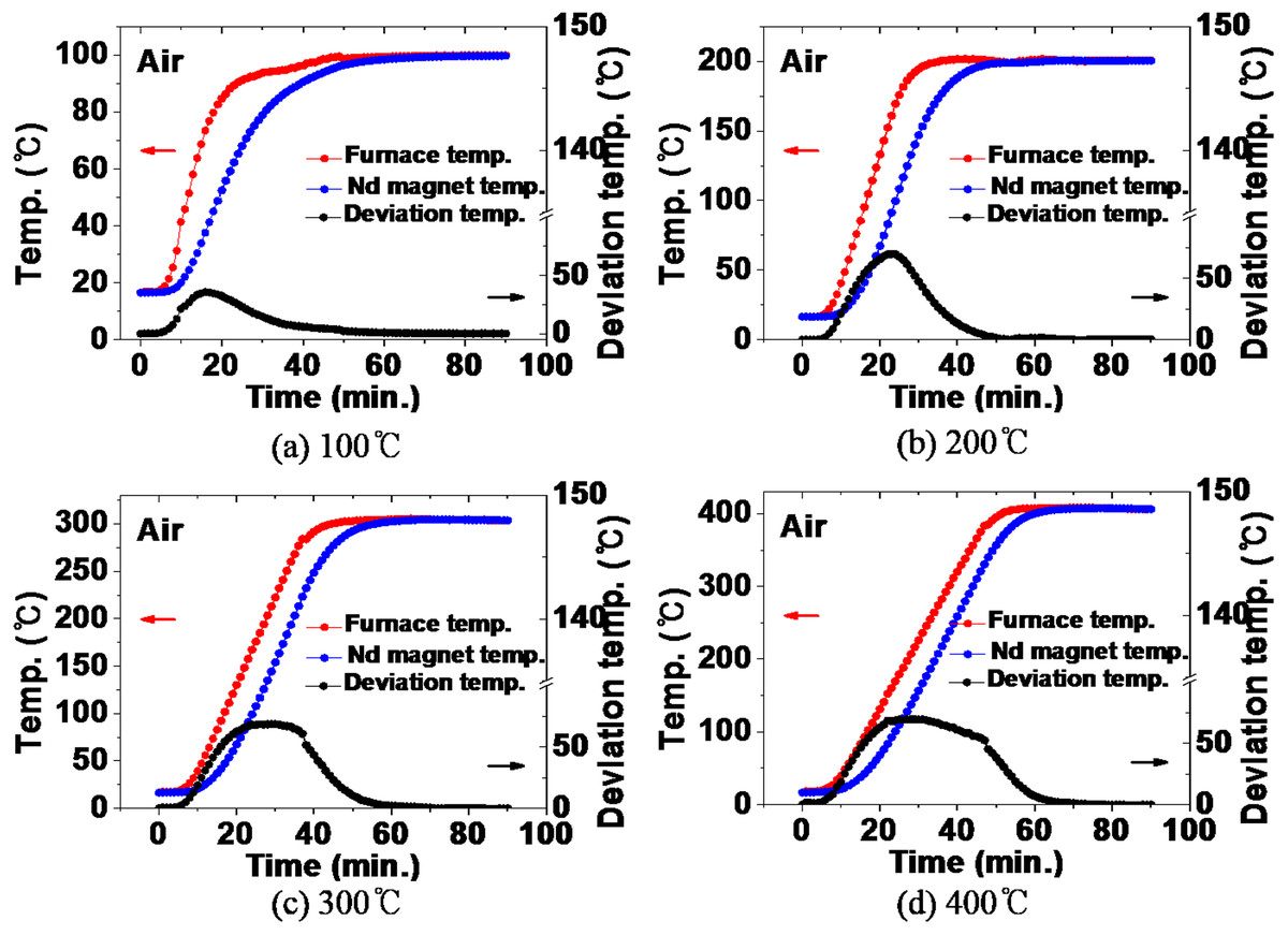
Figure 6: (A–D) Comparison of temperature inside the furnace and temperature of Nd magnet during heat treatment in air atmosphere.
The same behavior was shown at 200 °C, 300 °C, and 400 °C in Figs. 6B, 6C, and 6D, and the temperature deviation size and range tended to increase with the heat treatment temperature. As the temperature increases, so does the velocity of the fluid. Heat transfer by convection becomes more active, resulting in a faster rate of increase in the temperature inside the furnace. In contrast, the NdFeBM, where heat is transferred by thermal conduction between solids, is considered to have widened the deviation due to the relatively slow temperature rise. The final temperatures inside the furnace and magnet were 200 °C, 303 °C, and 406 °C respectively, showing a deviation of around 2% between the set temperature and the temperature of the magnet.
Figure 7 shows the temperature distribution in the furnace at 10-minute intervals during heat treatment in an air atmosphere, where the redness increases with set temperature. It can be seen that as the temperature rises the alumina boat containing the NdFeBM heat slower than the inside of the furnace. This results in a deviation between the temperature of the NdFeBM and the temperature inside the furnace. The temperature at the base of the furnace is lower due to the difference in the density of the fluid according to the temperature. It is considered that the temperature of the NdFeBM specimen part appears lower in the temperature rising section. At 100 °C in Fig. 7A, the temperature deviation was shown in the 0 to 40 minutes’ interval, and the largest temperature deviation was shown in the 20 min interval. This is consistent with the temperature deviation graph in Fig. 6A, and showed the same trend at 200 ∼ 400 °C.
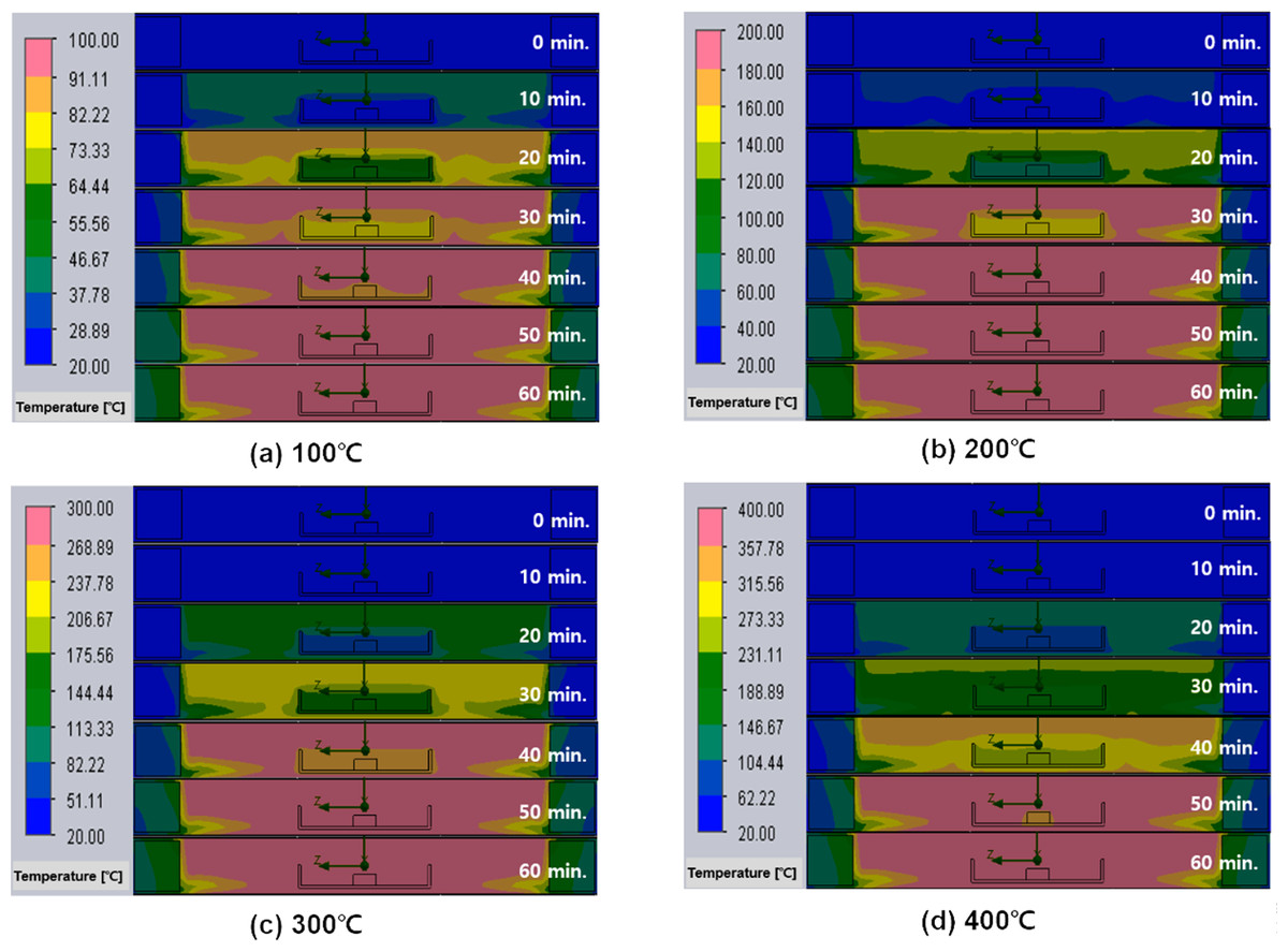
Figure 7: (A–D) Temperature distribution inside the furnace and Nd magnet over time of heat treatment in an air atmosphere.
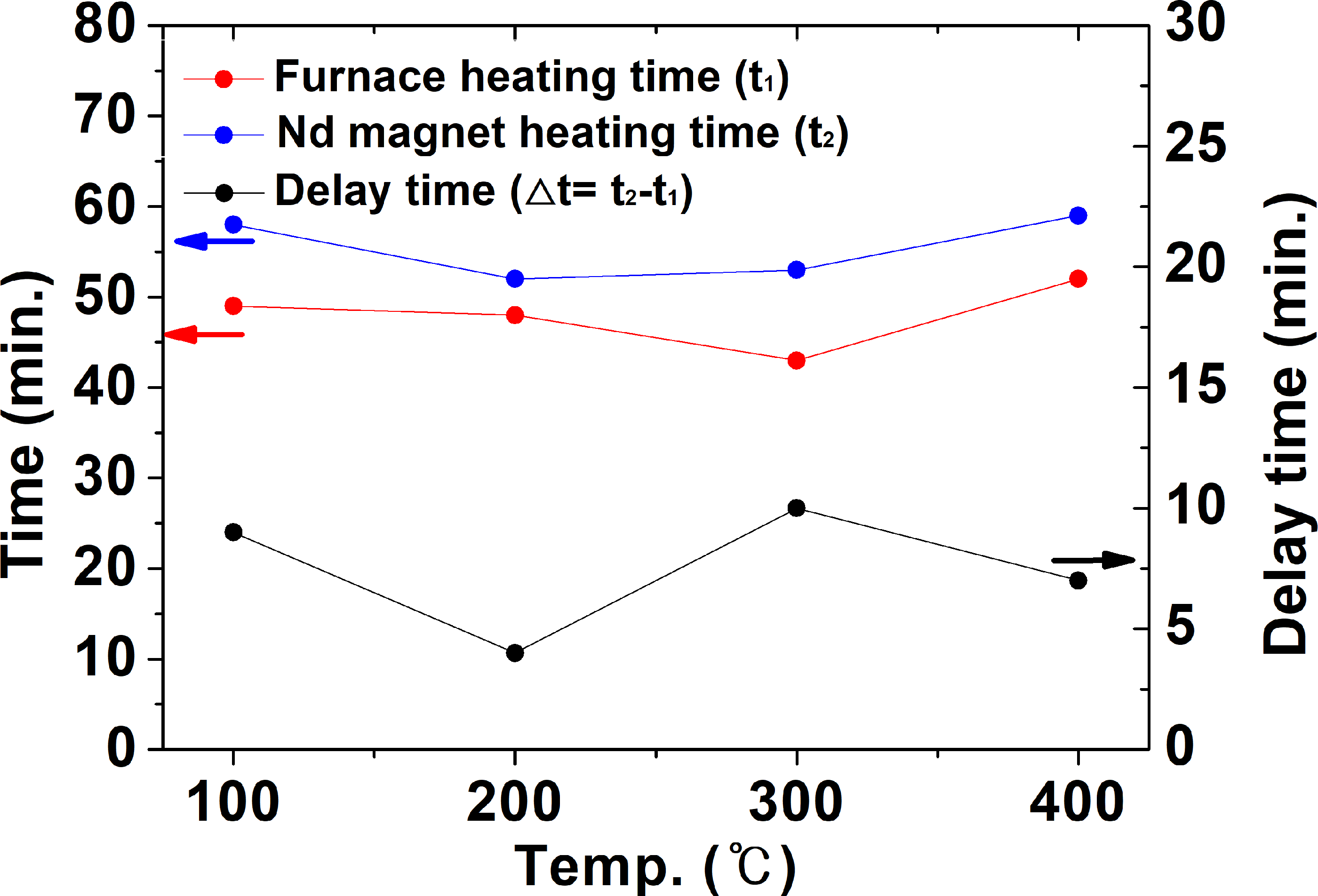
From Figs. 6 and 7, it is confirmed that the temperature deviation occurred due to the differencing rates of the temperature inside the NdFeBM and the furnace. The time for the furnace internal temperature to reach the set temperature from room temperature was defined as t1, and the time for the NdFeBM to reach the set temperature from room temperature as t2. Based on this, the delayed heat treatment time with the furnace internal temperature, which occurs when the NdFeBM reaches the set temperature, is defined as Δt (=t2–t1) as shown in Fig. 8.
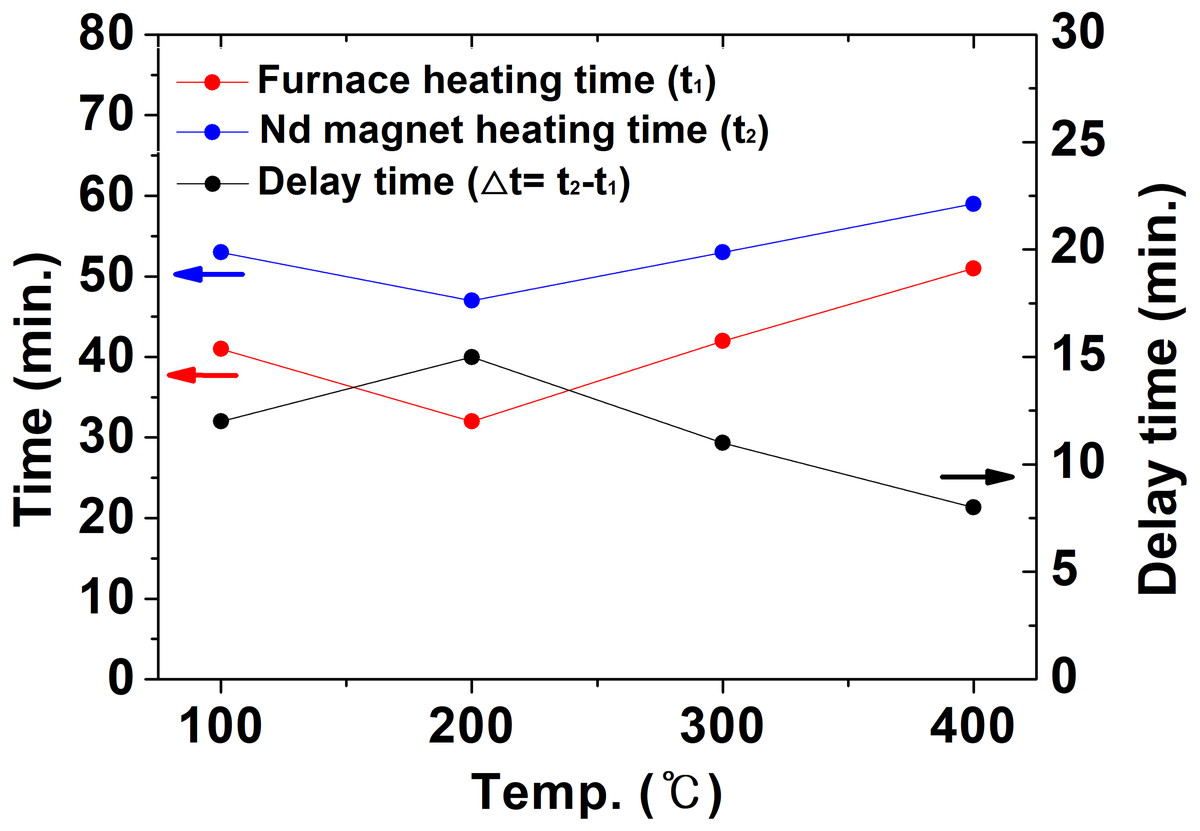
Figure 8: The time for the inside of the furnace and the Nd magnet to reach the set temperature in the air atmosphere and the delayed heat treatment time.
At 100 °C, t1 was 41 min after the start of heat treatment, t2 was 53 min, and Δt was 12 min. That is, after the temperature inside the furnace reaches the set temperature, the NdFeBM is also heated to the set temperature after about 12 min. Δt was 15 min at 200 °C, 11 min at 300 °C, and 8 min at 400 °C. As the heat treatment set temperature increased, the heat transferred by convection increased, and △t tended to decrease.
Figure 9 shows the comparison between the temperature inside the furnace and the thermal history of the NdFeBM specimen during heat treatment in a nitrogen atmosphere. During the heat treatment at 100 °C in Fig. 9A, the temperature inside the furnace was higher than that of the NdFeBM at 15 min, resulting in a temperature deviation of 31 °C. Thereafter, the temperature of the NdFeBM rose to 98 °C and the internal temperature of the furnace rose to 97 °C, maintaining a constant deviation of 1 °C. It is considered that the internal temperature of the furnace decreased due to the effect of nitrogen flow due to the predominance of heat transfer by convection. The temperature deviation occurred because the effect of nitrogen flow was small in the case of NdFeBM due to the predominance of heat conduction between solids. In the heat treatment at 200 °C, the final temperature of the NdFeBM is 199 °C while the internal temperature of the furnace is 197 °C, maintaining a temperature deviation of 2 °C. At 300 °C, the NdFeBM is 300 °C and the furnace internal temperature is 296 °C, maintaining a deviation of 4 °C. At 400 °C, the NdFeBM is 402 °C and the temperature inside the furnace is 395 °C, maintaining a 7 °C deviation. As the heat treatment temperature increased, the temperature inside the furnace appeared lower than the set temperature, this shows a tendency for the temperature deviation between the magnet and the inside of the furnace to increase. It is believed that the higher the temperature, the higher the convection phenomenon, activating an accelerated the heat loss due to the nitrogen flow, further reducing the internal temperature of the furnace.
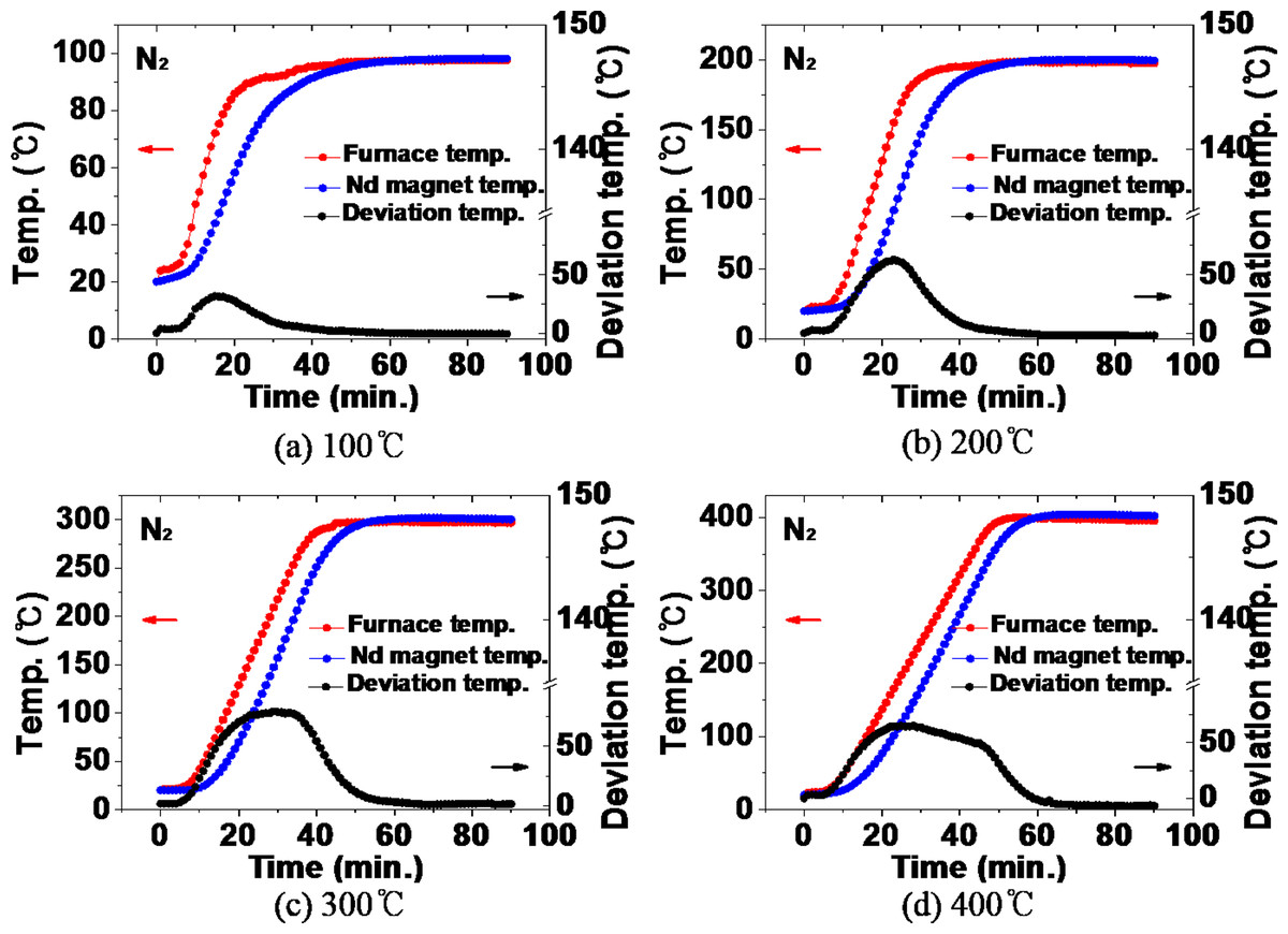
Figure 9: (A–D) Comparison of the temperature inside the furnace and the temperature of the Nd magnet during heat treatment in a nitrogen atmosphere.
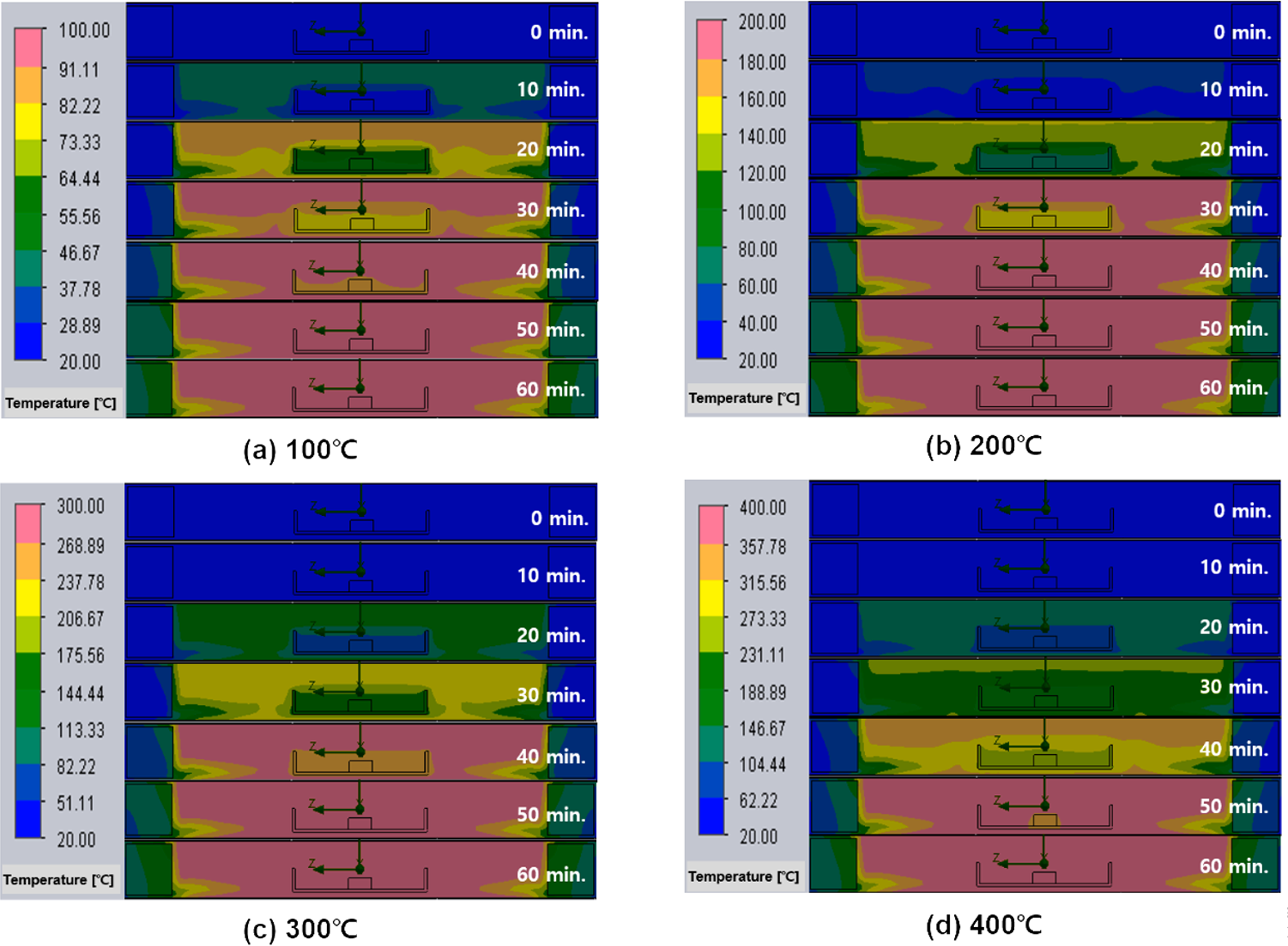
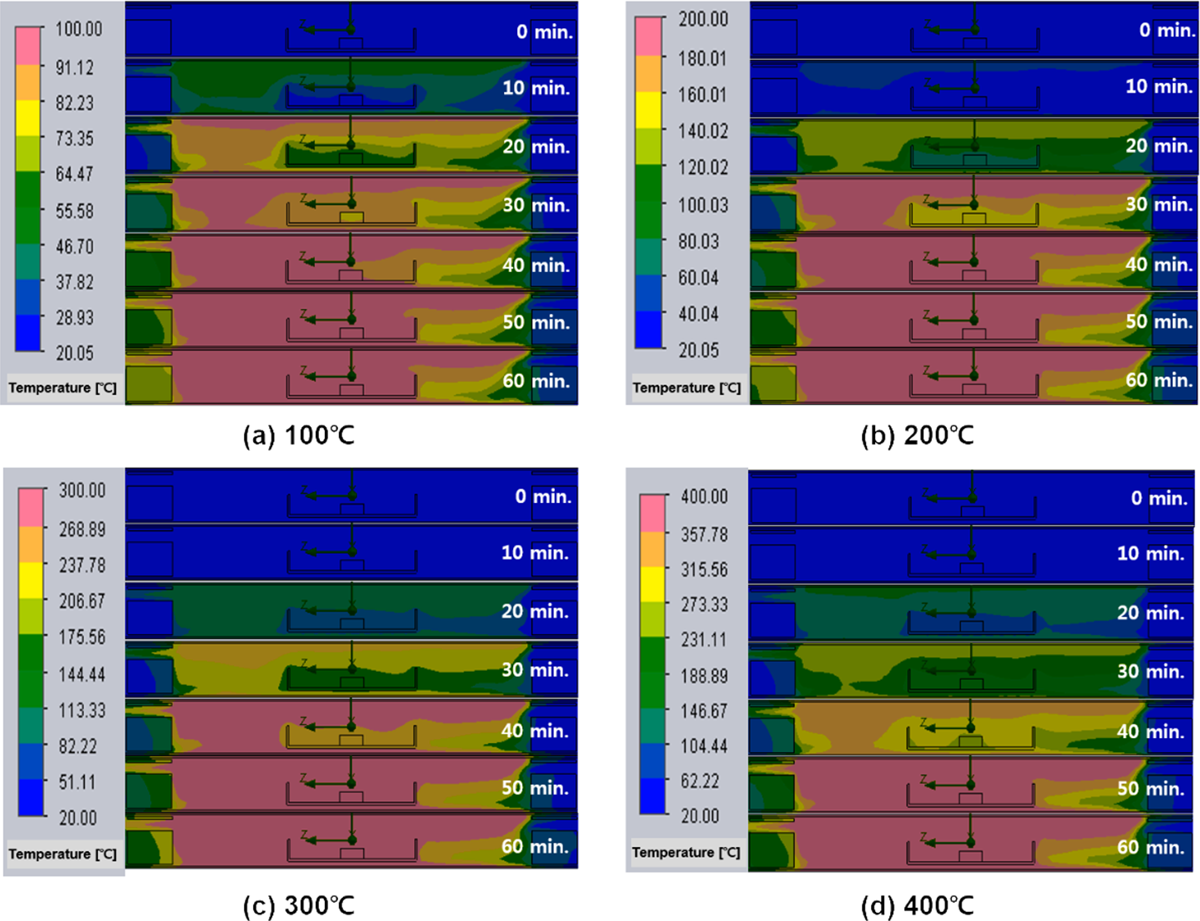
Figure 10 visually shows the temperature distribution inside the furnace during heat treatment in a nitrogen atmosphere. It can be seen that there is a deviation in the distribution of heat along the path where nitrogen flows in and out. Looking at the temperature distribution inside the furnace, a relatively unheated flow of low-temperature nitrogen is observed from the right insulating block into which the initial nitrogen is introduced to the wall of the alumina boat. Nitrogen appears to also come into contact with the surface of the NdFeBM along the surface of the alumina boat. As the heat treatment time elapses, the temperature of the left insulating block through which nitrogen is discharged increases more than that of the right insulating block. It is considered that this is due to heat loss occurring inside the furnace through discharging to the outside along the flow of nitrogen. Therefore, it is thought that the temperature inside the furnace is lower than the temperature of the NdFeBM as the heat loss that occurred due to the inflow and outflow of nitrogen gas.
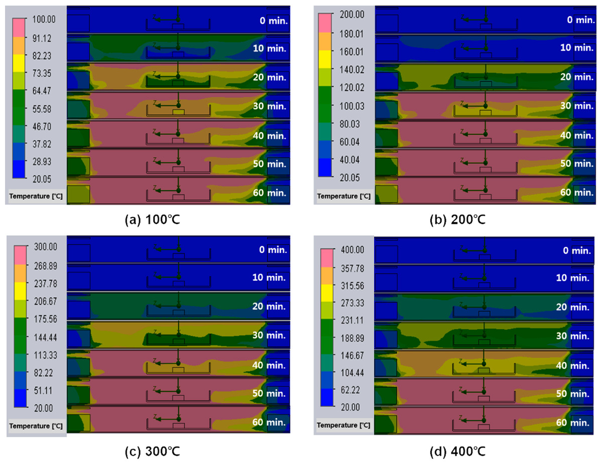
Figure 10: (A–D) Temperature distribution inside the furnace and Nd magnet over time of heat treatment in a nitrogen atmosphere.
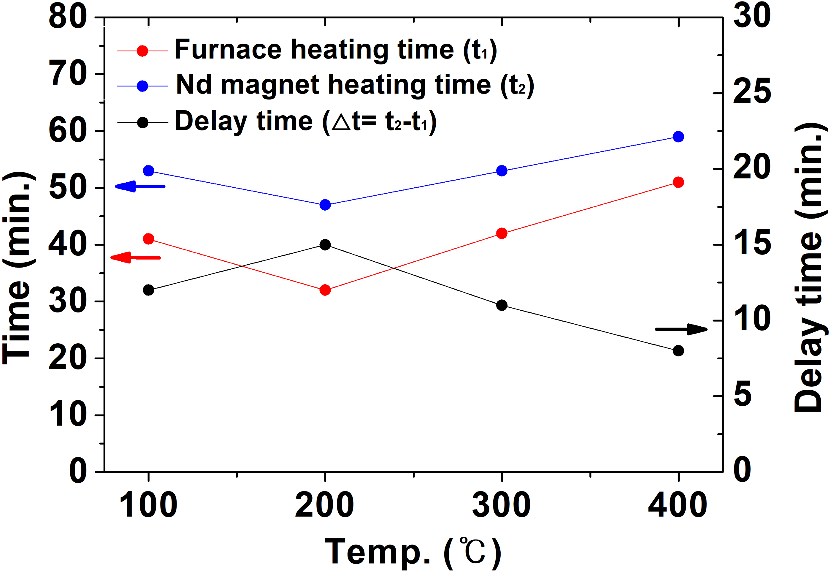
Figure 11 compares t1, t2, and △t during heat treatment in a nitrogen atmosphere. The time (t2) for the temperature of the NdFeBM to reach the set temperature was similar to the air atmosphere heat treatment result in Fig. 8. On the other hand, the temperature inside the furnace decreased from heat loss due to nitrogen flow and the time (t1) for the temperature inside the furnace to reach the set temperature was greatly increased. Hence, it is considered that Δt decreases compared to the air atmosphere. Through examining the thermal history behavior of NdFeBM with computer simulation, the delayed heat treatment time generated in the air atmosphere heat treatment was more than 10 min and 15 min in the air atmosphere. Therefore, in order to accurately control the temperature of the NdFeBM during the demagnetization heat treatment, the demagnetization heat treatment conditions must be determined in consideration of the delay time.
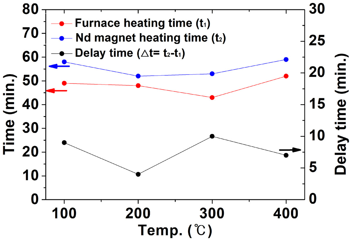
Figure 11: The time for the inside of the furnace and the Nd magnet to reach the set temperature and the required temperature holding time in a nitrogen atmosphere.
Figure 12 shows the internal pressure of the furnace according to the heat treatment setting temperature. Since the distribution of pressure inside the furnace appears uniform, the pressure value was based on the average value when the temperature inside the furnace and the NdFeBM reached the set temperature. Since the air atmosphere is a heat flow analysis in a closed system, the pressure of 1.1 ∼ 1.6 atm tended to increase slightly as the heat treatment set temperature increased. In the nitrogen atmosphere, since it is an open system in which nitrogen gas flows, the pressure was constant with almost no change.
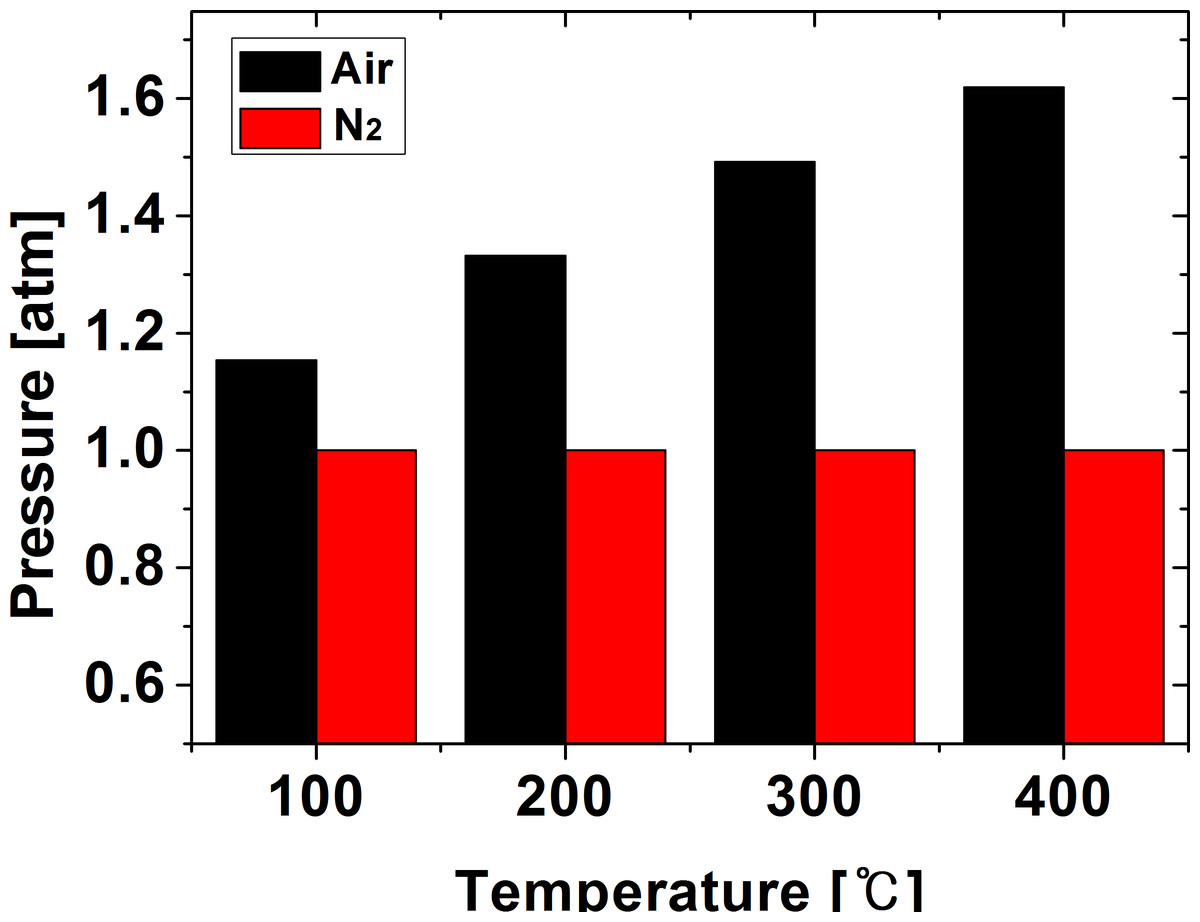
Figure 12: Residual flux value and magnetization rate according to demagnetization temperature of Nd magnet.
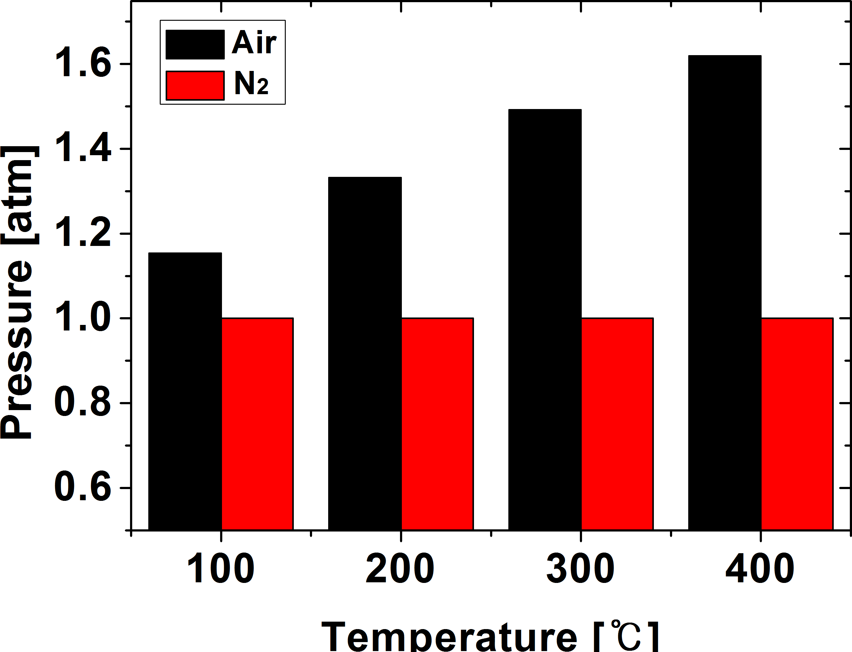
Demagnetization and magnetization of NdFeBM
Demagnetization heat treatment was performed in consideration of the heat treatment delay time previously reviewed with computer simulation. The NdFeBM was heat treated in the temperature range of 100 to 400 °C by setting the heat treatment holding time to 30 min in an air atmosphere and a nitrogen atmosphere. Residual flux was measured to confirm the flux change of the heat-treated NdFeBM. In order to confirm the possibility of reuse, the magnetization rate was calculated by measuring the residual flux after magnetization with the magnetization facility, and how much the magnetic flux was recovered compared to the initial period. The magnetization was performed by changing the charging voltage from the capacitor of the power facility to 2000V, 2500V, and 3000V, and the magnetization energy to 6,000J, 9,375J, and 13,500J, respectively.
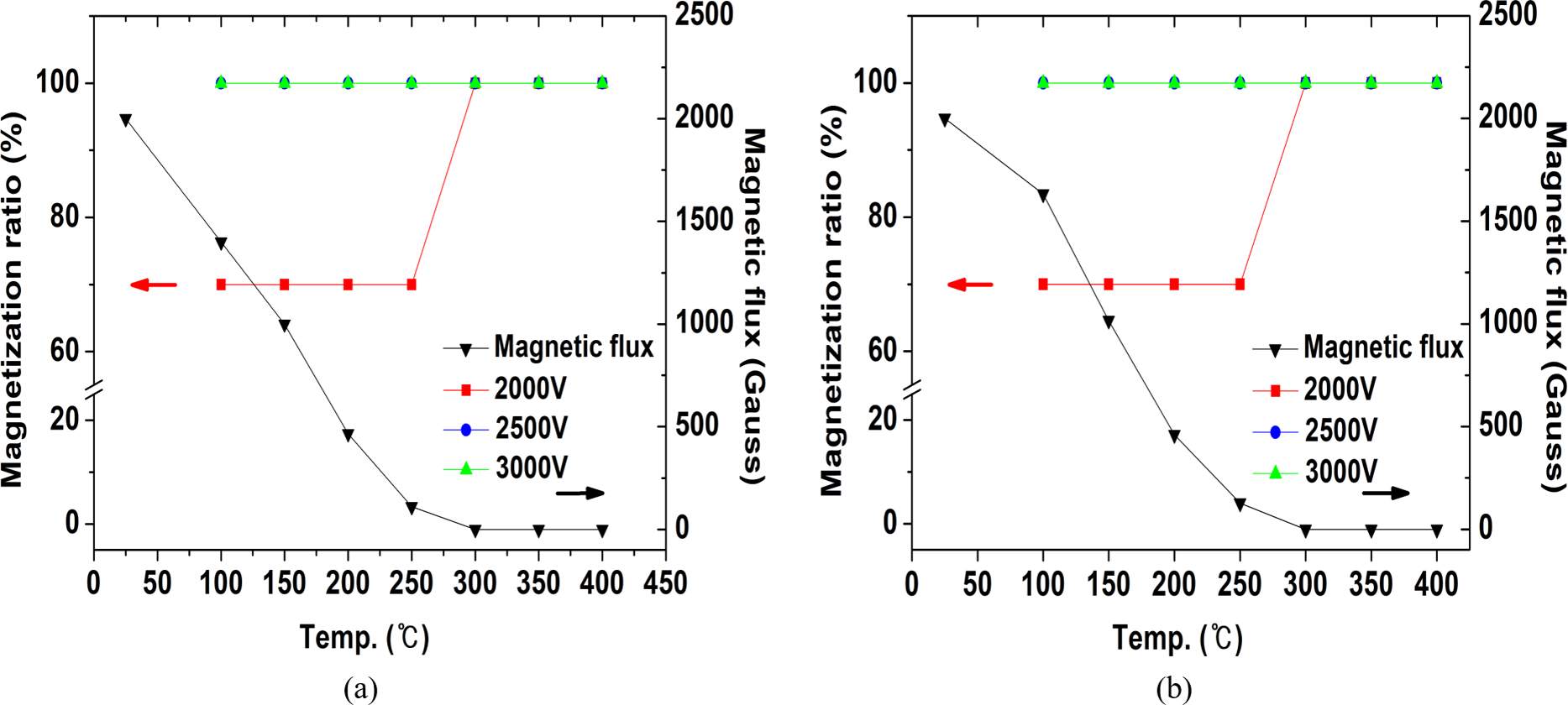
Figure 13 shows the results of the residual flux measurement and magnetization rate of NdFeBM demagnetized by temperature. The initial residual flux of the NdFeBM demagnetized in the air was 2000 G, 1400 G at 100 °C, 980 G at 150 °C, 433 G at 200 °C, and 100 G at 250 °C. At 300 °C, it was completely demagnetized and decreased to 0 G. An NdFeBM that was not completely demagnetized was only 70% magnetized when a magnetization energy of 6,000 J was applied. The fully demagnetized NdFeBM heat treated in the range of 300 °C to 400 °C had a magnetization rate of 100%. When the magnetization energy was increased to 9,375J and 13,500J, the magnetization rate was 100% despite the residual flux.
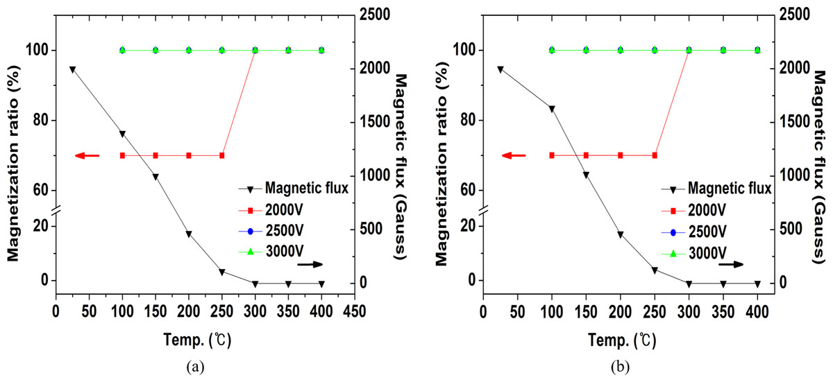
Figure 13: Residual flux value and magnetization rate according to demagnetization temperature of NdFeBM.
Figure 13B shows the results of the residual flux and magnetization rate of the NdFeBM subjected to demagnetization heat treatment in a nitrogen atmosphere. Similarly, the initial flux value was 2000 G. Residual fluxes of 1500 G at 100 °C, 1000 G at 150 °C, 466 G at 200 °C, and 110 G at 250 °C were measured. Above 300 °C, it was completely demagnetized to 0 G, same as the air atmosphere. Although the temperature of the NdFeBM in the nitrogen atmosphere was found to be 1 ∼ 4 °C lower than that in the air atmosphere, the effect of nitrogen inflow on the demagnetization temperature is considered to be insignificant. The NdFeBM with residual flux remained only 70% magnetized at 6,000 J, and completely magnetized at 9,375 J and above. The NdFeBM subjected to demagnetization heat treatment at 300 ∼ 400 °C was completely magnetized regardless of the charging voltage, showing the same tendency as the atmospheric atmosphere.
The heat treatment atmosphere did not affect the demagnetization efficiency of the NdFeBM, and more energy was required for magnetization if the residual flux value remained after demagnetization. Therefore, it is preferred to completely demagnetize the NdFeBM for efficient magnetization.
Analysis of the plating layer surface of NdFeBM after demagnetization heat treatment
Since NdFeBM are very vulnerable to corrosion from oxidation, a surface coating layer is formed to prevent corrosion. The NdFeBM used in this study is the most commonly used type of plating layer in the form of Ni/Cu/Ni. To demagnetize the NdFeBM, heat treatment is required at a temperature of 300 °C. or higher. In the case of heat treatment of magnets in large quantities, it is expected that heat treatment of 350 °C or more is required to sufficient heat transfer may be difficult with NdFeBM. However, during high-temperature heat treatment, the inner composition of the plating layer of the NdFeBM is altered and oxidized, which can damage the function (Nababan et al., 2021). Hence, in this study, the integrity of the plated layer surface of NdFeBM according to the demagnetization heat treatment conditions was studied for reuse of NdFeBM.
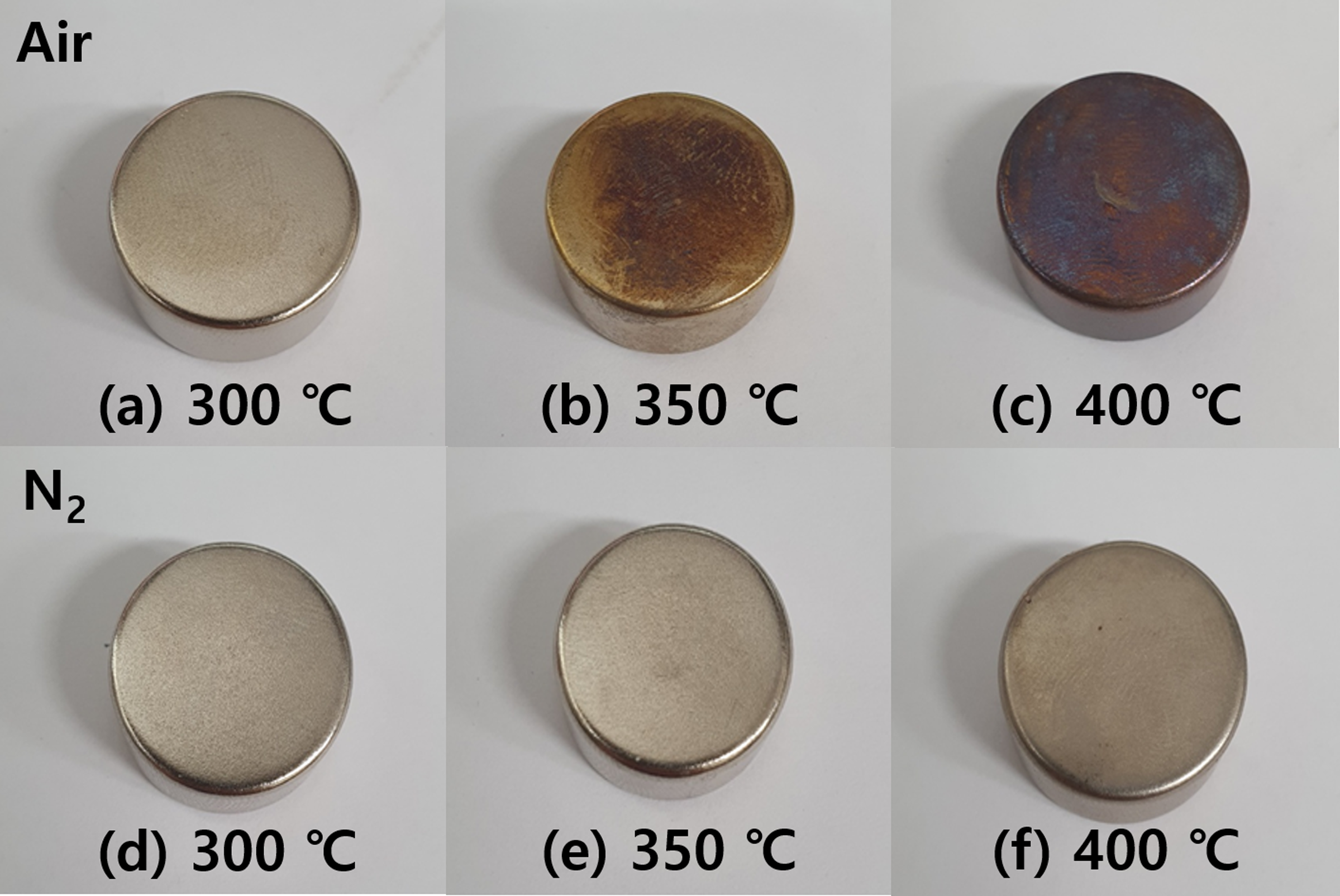
Figures 14A, 14B, 14C shows the discoloration of the NdFeBM surface heat-treated in an air atmosphere with an optical camera. No signs of discoloration were seen at 300 °C. At 350 °C, discoloration began and the surface took on a brass color at 400 °C, it can be seen that discoloration progressed further. On the other hand, in a nitrogen atmosphere, there was no sign of discoloration from 300 to 350 °C, and only a change in the gloss of the NdFeBM plating layer disappeared at 400 °C.
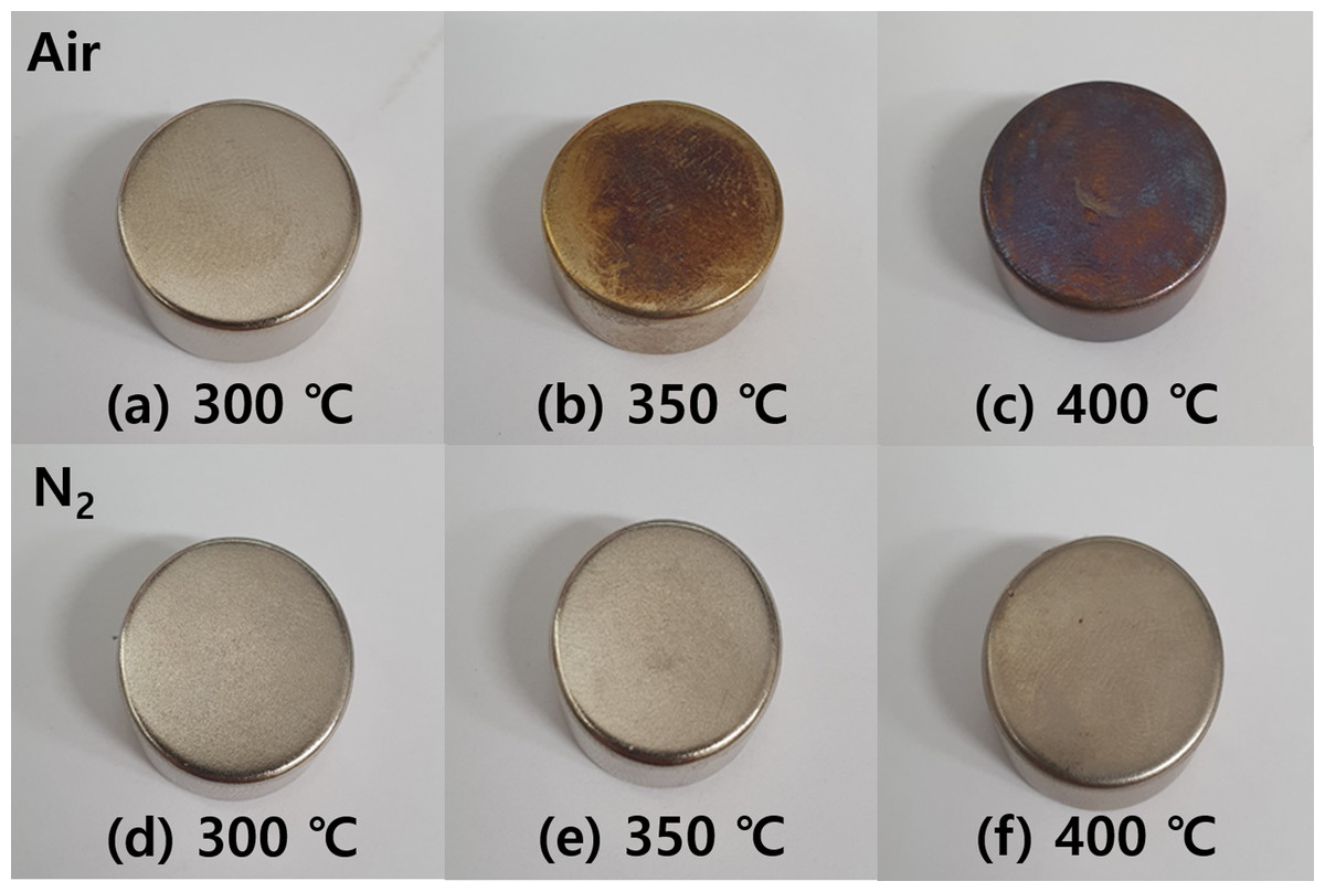
Figure 14: (A–D) Discoloration of NdFeBM surface according to demagnetization heat treatment atmosphere and temperature.
Table 3 shows the results of compositional analysis by EDS of the NdFeBM surface subjected to demagnetization heat treatment in air and nitrogen atmospheres. During heat treatment at 300 °C in an air atmosphere, 99% Ni and 1% O were detected on the surface. At 350 °C, 2.08% of Cu was detected on the surface and O increased to 1.77%. Due to the high temperature, it seems that the Cu layer inside the Ni/Cu/Ni plating layer diffused to the surface. It is believed that the discoloration of the surface in Fig. 14B is due to the formation of CuO by the reaction of Cu diffused on the surface with oxygen in the air. At 400 °C, the surface composition is 11.08% Cu and 4.39% O, consequently, the oxidation of Cu proceeds and the discoloration intensifies.
| Temp. [°C] |
Composition [wt%] | |||
|---|---|---|---|---|
| Ni | Cu | O | ||
| Air | 300 | 99.01 | – | 0.99 |
| 350 | 96.15 | 2.08 | 1.77 | |
| 400 | 84.53 | 11.08 | 4.39 | |
| N2 | 300 | 99.79 | – | 0.21 |
| 350 | 99.58 | – | 0.42 | |
| 400 | 97.27 | 2.09 | 0.64 | |
The surface of the NdFeBM heat treated at 300 ∼ 350 °C in a nitrogen atmosphere was 0.21 ∼ 0.42% O, which suppressed oxidation compared to the air atmosphere, and no signs of Cu diffusion or discoloration were found, so the surface integrity could be maintained. At 400 °C, 2.09% of Cu was detected, but it was thought that oxidation was suppressed due to nitrogen atmosphere and discoloration did not occur as shown in Fig. 14F.
As the heat treatment temperature of the NdFeBM increased, Cu and O on the surface of the plating layer of the magnet increased, resulting in a significant change in the surface composition.
Therefore, discoloration does not occur when demagnetization heat treatment is performed at 300 °C in an air atmosphere, and it is determined that the nitrogen atmosphere is the most suitable condition for stable demagnetization heat treatment without surface discoloration and compositional change up to 350 °C.
Conclusions
In order to establish the demagnetization heat treatment conditions of the NdFeBM, computational simulation was performed under the temperature conditions at 100 ∼ 400 °C in an air atmosphere and a nitrogen atmosphere.
During the demagnetization heat treatment, a lag time occurred between the time for the temperature inside the furnace to reach the set temperature and the time for the temperature of the NdFeBM to reach the set temperature. In the air atmosphere, the delay time was up to 15 min, and in the nitrogen atmosphere, the delay time was up to 10 min. Considering the mass effect of the magnet, it was determined that a temperature holding time that compensates for the delay time of at least 30 min is necessary for accurate temperature control.
The NdFeBM was heat treated from 100 ∼ 400 °C in consideration of the delay time, and it was confirmed that the residual magnetic flux decreased as the heat treatment temperature increased, completely demagnetizing at 300 °C.
NdFeBM heat treated up to 250 °C, which is below the demagnetization temperature, were difficult to magnetize due to the presence of residual magnetic flux. NdFeBM completely demagnetized at 300 °C or higher were magnetized to the level of new magnets.
During the demagnetization heat treatment from 300 ∼ 400 °C, the degree of oxidation on the surface of the NdFeBM plating layer increased by 1% to 4% as the temperature increased in the air atmosphere, and discoloration occurred from 350 °C. In the case of heat treatment in a nitrogen atmosphere, as the demagnetization heat treatment temperature increased, the degree of oxidation was 0.2 ∼ 0.6%. There was an oxidation inhibitory effect, and discoloration did not occur until 350 °C.
It was confirmed that stable demagnetization heat treatment is possible without changing or damaging the composition of the surface up to 350 °C in a nitrogen atmosphere where oxidation is suppressed, and the demagnetized NdFeBM can be magnetized and reused.