The CryoEM structure of the Saccharomyces cerevisiae ribosome maturation factor Rea1
- Institut de Génétique et de Biologie Moléculaire et Cellulaire, France
- Centre National de la Recherche Scientifique, UMR7104, France
- Institut National de la Santé et de la Recherche Médicale, U964, France
- Université de Strasbourg, France
- MRC Laboratory of Molecular Biology, United Kingdom
Figures
Figure 1 with 7 supplements
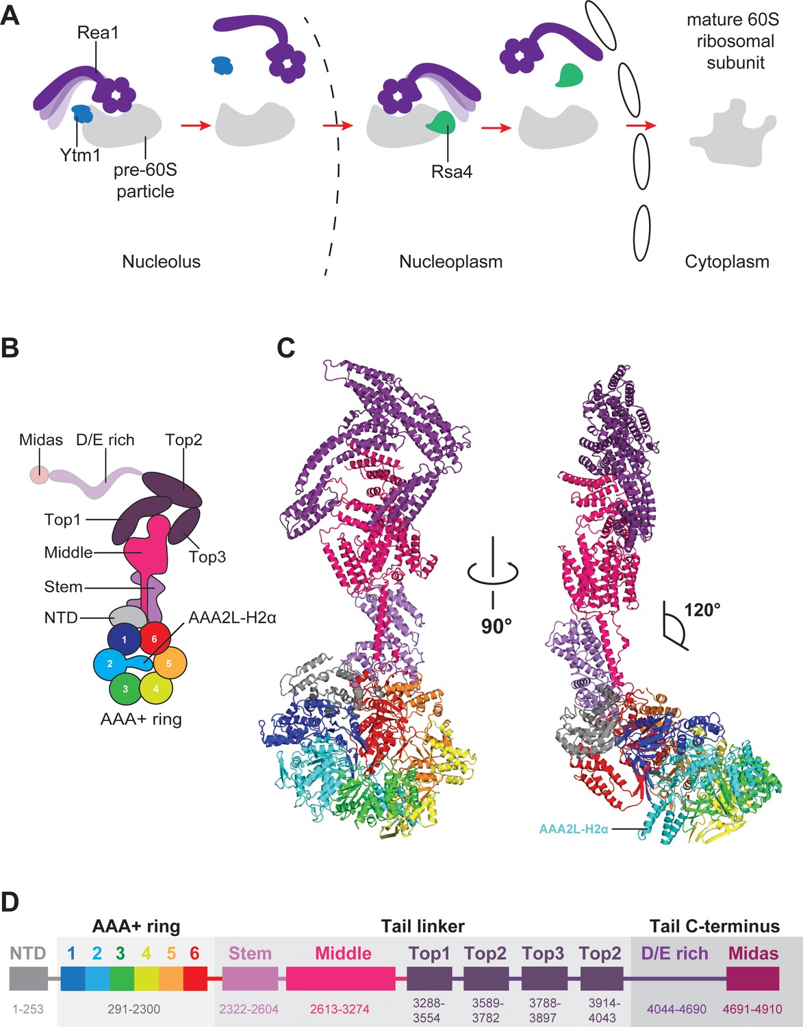
Function and structure of Rea1.
(A) Schematic representation of the reactions catalysed by Rea1. (B) Cartoon representation of the Rea1 structure showing the N-terminal domain, the AAA+ ring as well as the stem, middle and top domains of the linker. The top3 domain is an insertion of the top2 domain. The C-terminal D/E-rich region and the MIDAS domain of the tail are not visible as indicated by their transparent representation. (C) Front (left panel) and side view (right panel) of the Rea1 structure. The AAA2L-H2α insert occupies the central pore of the AAA+ ring. The linker region of the tail emerges at an angle of about 120° from the AAA +ring. (D) Colour-coded primary sequence representation of Rea1 domains.
Figure 1—figure supplement 1
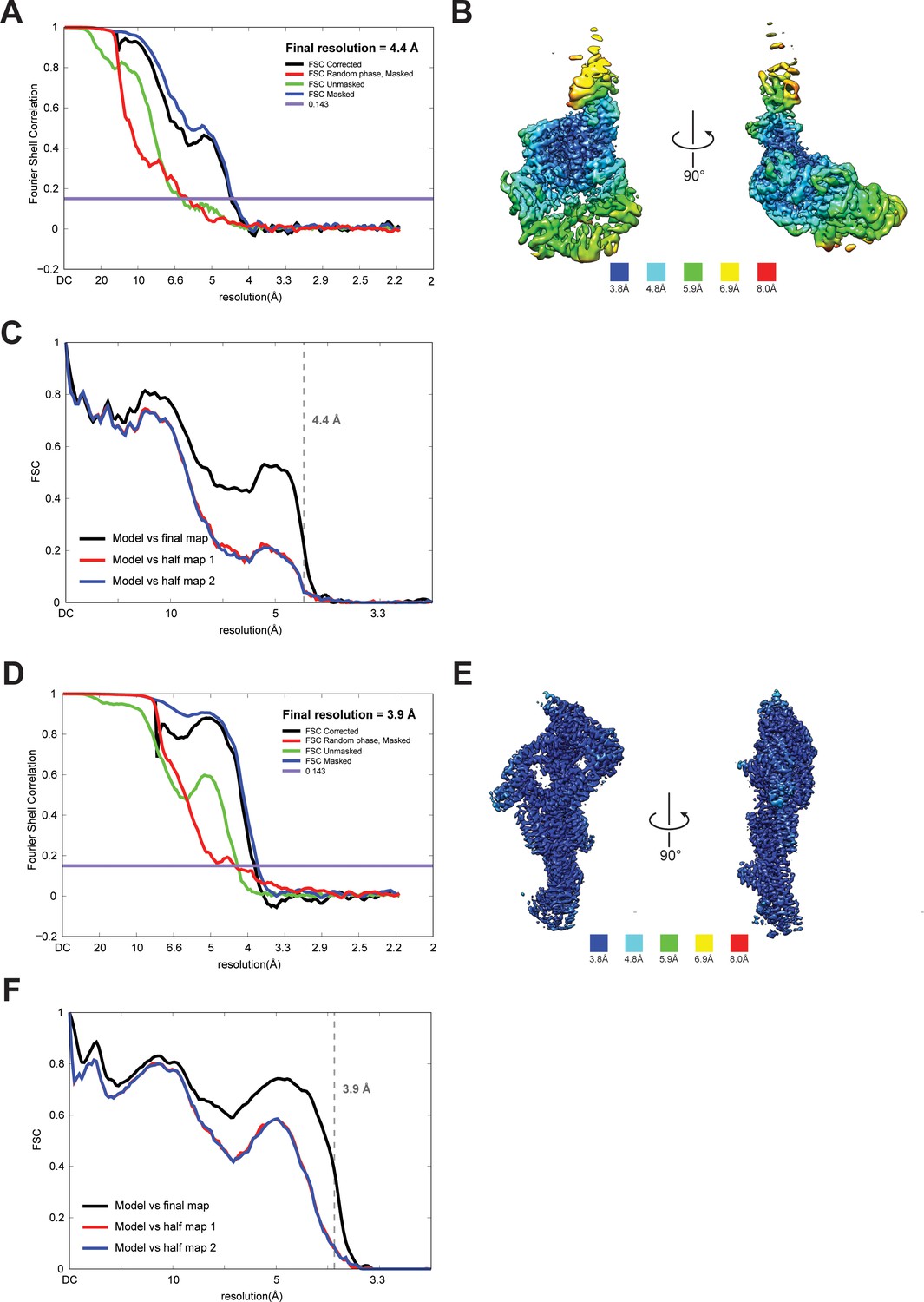
Quality of NTD-AAA + ring and linker cryoEM maps.
(A) Fourier shell correlation (FSC) plot for half-maps of the NTD-AAA+ ring reconstruction. The 0.143 FSC criteria is indicated as horizontal blue line. The final overall resolution is 4.4 Å. (B) Local resolution of the NTD-AAA+ ring reconstruction. (C) Model vs map FSC curves for final NTD-AAA+ ring model versus final NTD-AAA+ ring map. (D) Fourier shell correlation (FSC) plot for half-maps of the linker reconstruction. The 0.143 FSC criteria is indicated as horizontal blue line. The final overall resolution is 3.9 Å. (E) Local resolution of the linker reconstruction. (F) Model vs map FSC curves for final linker model versus final linker map.
Figure 1—figure supplement 2
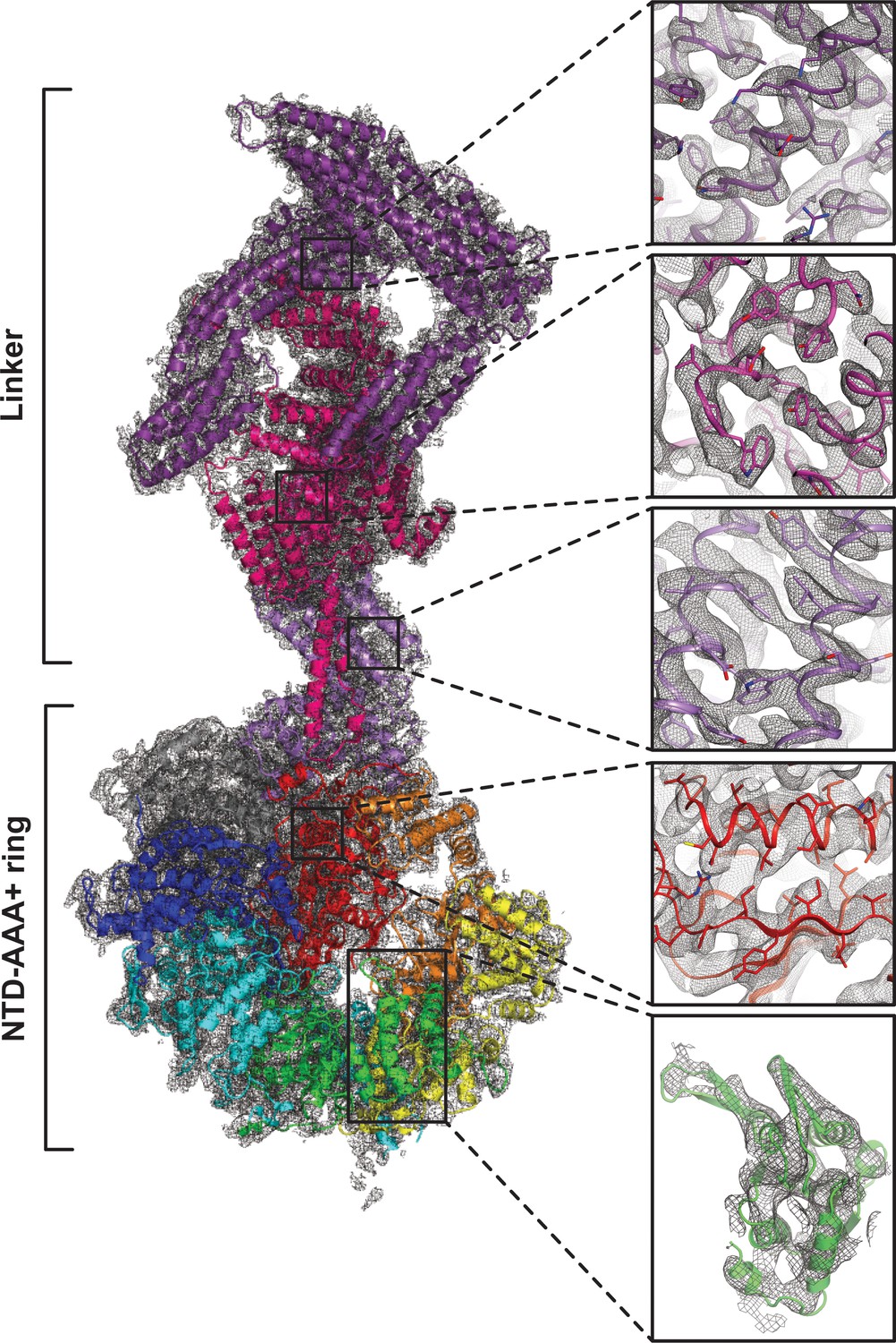
Quality of composite NTD-AAA+ ring linker cryoEM map.
The insets show the map quality in the linker top (purple), the linker middle domain (pink), the linker stem (violet), AAA6L (red) and AAA3L (green).
Figure 1—figure supplement 3
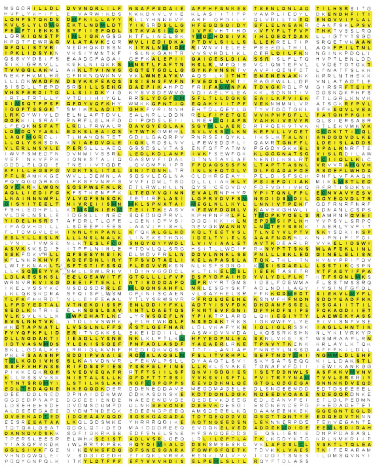
Rea1 mass spectrometry analysis after tryptic digest.
The identified peptides of S. cerevisiae Rea1 are shown in yellow. Methionine and cysteine residues highlighted in green indicate mass shifts due to sulphur oxidation. The sequence coverage level is 55%.
Figure 1—figure supplement 4
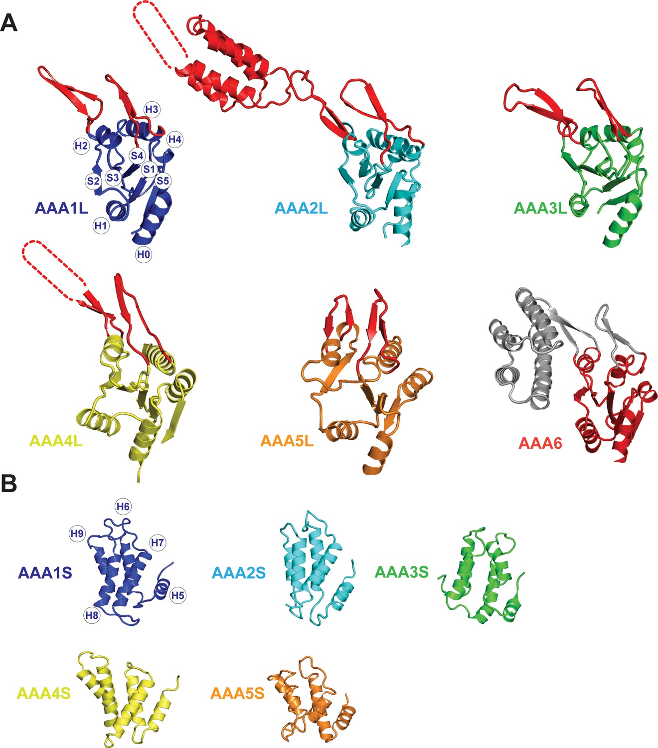
Core architecture of the Rea1 AAA +subunits.
(A) Core architecture of AAAL domains. Secondary structure elements are labelled for AAA1L. All Rea1 AAAL’s have β-sheet inserts in H2 as well as between H3 and S4 (red, grey for AAA6L) In AAA2L, AAA4L, and AAA6L the H2 β-sheet is extended by an α-helical bundle. For the AAA2L H2 α-helical bundle, four out of the five predicted α-helices can be located in the cryoEM maps. The predicted three α-helices of the AAA4L H2 α-helical bundle cannot be assigned in the maps. Missing regions within the H2 α-helical bundles are indicated by dotted lines. For AAA6L, all four α-helices of the AAA6L H2 α-helical bundle are visible. (B) Core architecture of the AAAS domains. Secondary structure elements are labelled for AAA1S. The core of all small domains consists of five α-helices. AAA6S is not present in Rea1.
Figure 1—figure supplement 5
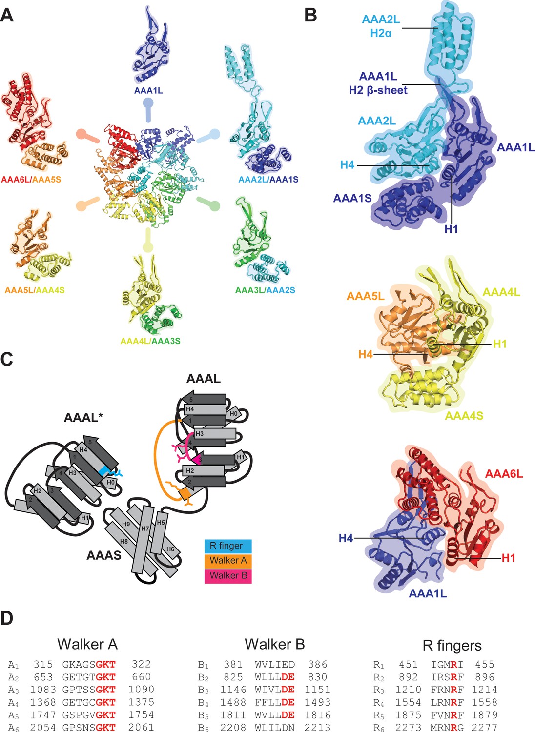
AAA+ ring architecture and nucleotide binding.
(A) In the Rea1 AAA+ ring each AAAL domain is tightly associated with the AAAS domain of the previous AAA+ module to form the following modules: AAA2: AAA2L-AAA1S, AAA3: AAA3L-AAA2S, AAA4: AAA4L-AAA3S, AAA5: AAA5L-AAA4S, and AAA6: AAA6L-AAA5S. The AAA1 module only exists of AAA1L because an AAA6S domain does not exist in Rea1. (B) The AAA+ nucleotide binding sites are located at the interface between neighbouring AAA+ domains. Each AAAL domain binds ATP via its Walker-A motif at the H1 helix. H4 of the neighbouring AAAL domain carries an arginine finger that promotes ATP-hydrolysis. For ATP hydrolysis to occur, both domains have to come together to bring the arginine finger at H4 into close contact with the nucleotide bound at the Walker-A motif of H1. The nucleotide-binding sites of Rea1 AAA1 (consisting of AAA1L/AAA1S/AAA2L), AAA4 (consisting of AAA4L/AAA4S/AAA5L), and AAA6 (consisting of AAA6L/AAA1L) are shown. Sites AAA1 and AAA6 are closed. The AAA4 site has an unusual architecture because AAA4L is rotated with respect to AAA5L (see main text). Sites AAA2, AAA3 and AAA5 are shown in Figure 2. (C) Schematic representation of an AAA+ nucleotide binding site. H1 carries the Walker-A motif (GKT) responsible for ATP binding. The C-terminal tip of S3 carries the Walker-B motif (DE) that activates a water molecule for the nucleophilic attack on the ATP γ-phosphate. H4 of the neighbouring AAAL domain (AAAL*) carries the arginine finger that stabilises the ATP-hydrolysis transition state. (D) The Walker-A, the Walker-B and the arginine finger motifs of Rea1 AAA+ domains. AAA1 and AAA6 lack the Walker-B motifs and cannot hydrolyse ATP at their sites. The arginine finger at AAA1 for S. cerevisiae Rea1 is not conserved in other species.
Figure 1—figure supplement 6
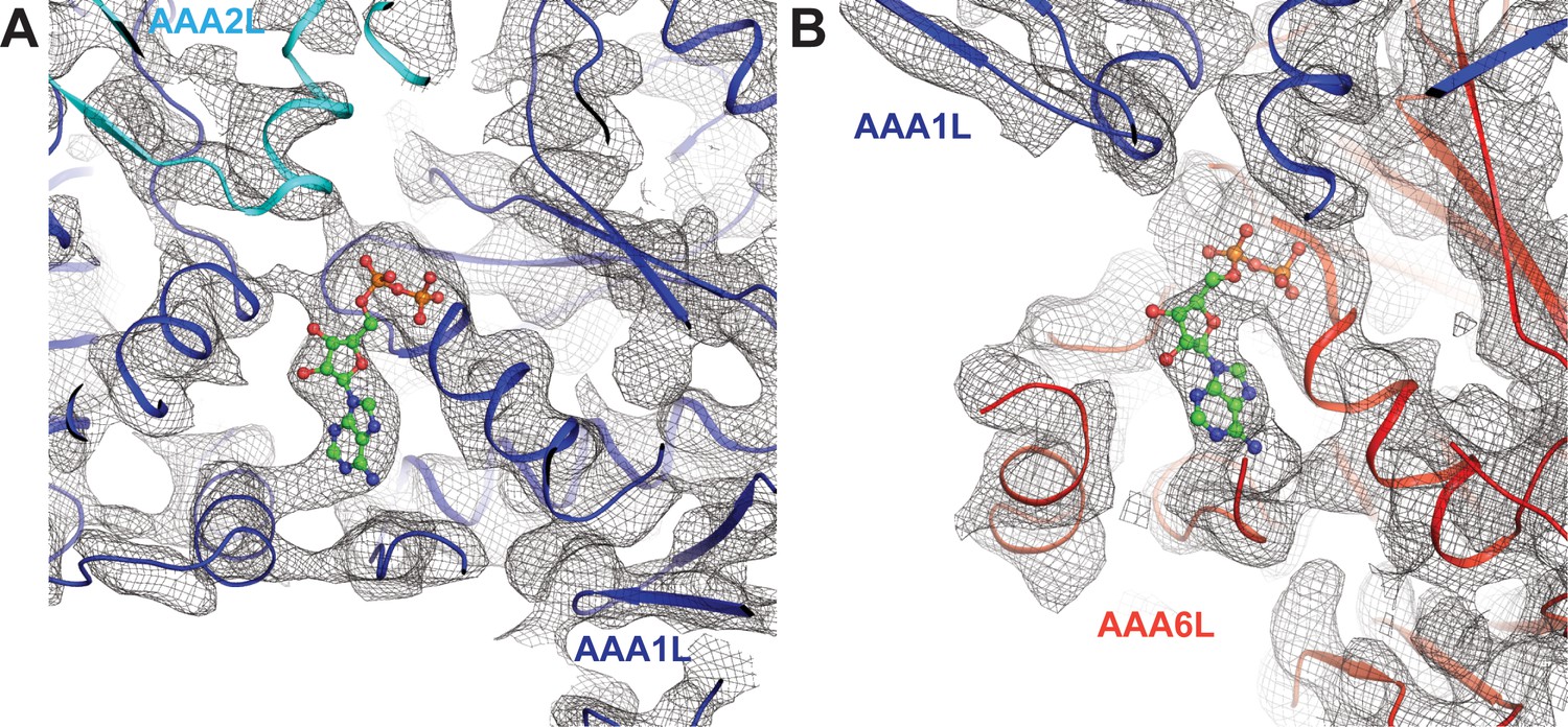
Nucleotide binding at the Rea1 AAA1 and AAA6 sites.
(A) Nucleotide density of the AAA1 site. (B) Nucleotide density at the AAA6 site. The densities are consistent with an ADP molecule (shown in balls and stick representation).
Figure 1—figure supplement 7
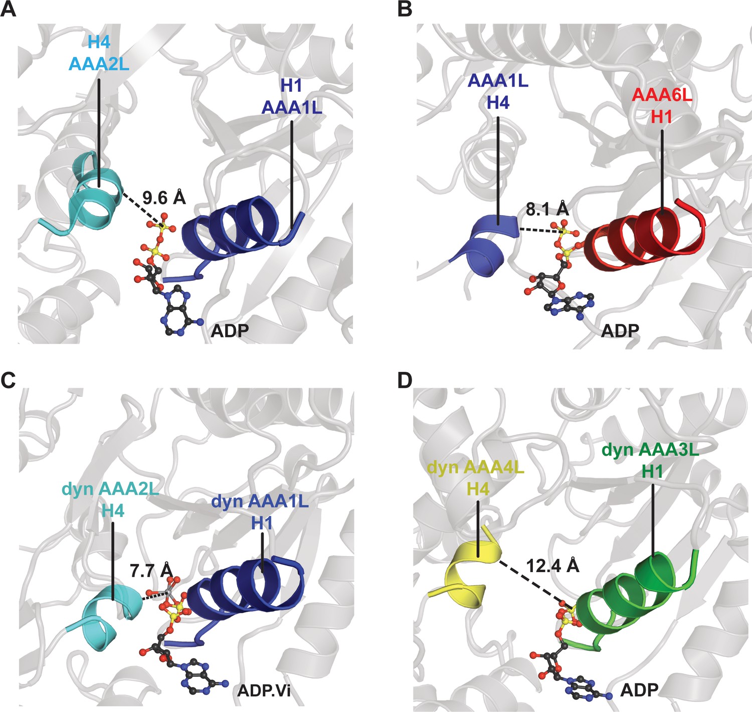
Comparison of the Rea1 AAA1 and AAA6 nucleotide-binding sites with the dynein AAA1 and AAA3 nucleotide-binding sites.
To analyse the degree of site closure, we compared the distance between the terminal phosphate or vanadate group of the nucleotide and the H4 α-helix, which harbours the arginine finger motif. In Rea1, this distance is (A) 9.6 Å for the AAA1, and (B) 8.1 Å for the AAA6 site. In dynein (PDB-ID: 4RH7), the H4-nucleotide distance is (C) 7.7 Å in the completely closed AAA1 site, and (D) 12.4 Å in the more open AAA3 site. This comparison suggests that the Rea1 AAA6 site is already completely closed in the ADP state, whereas the Rea1 AAA1 site might further close when bound to ATP.
Figure 2 with 2 supplements
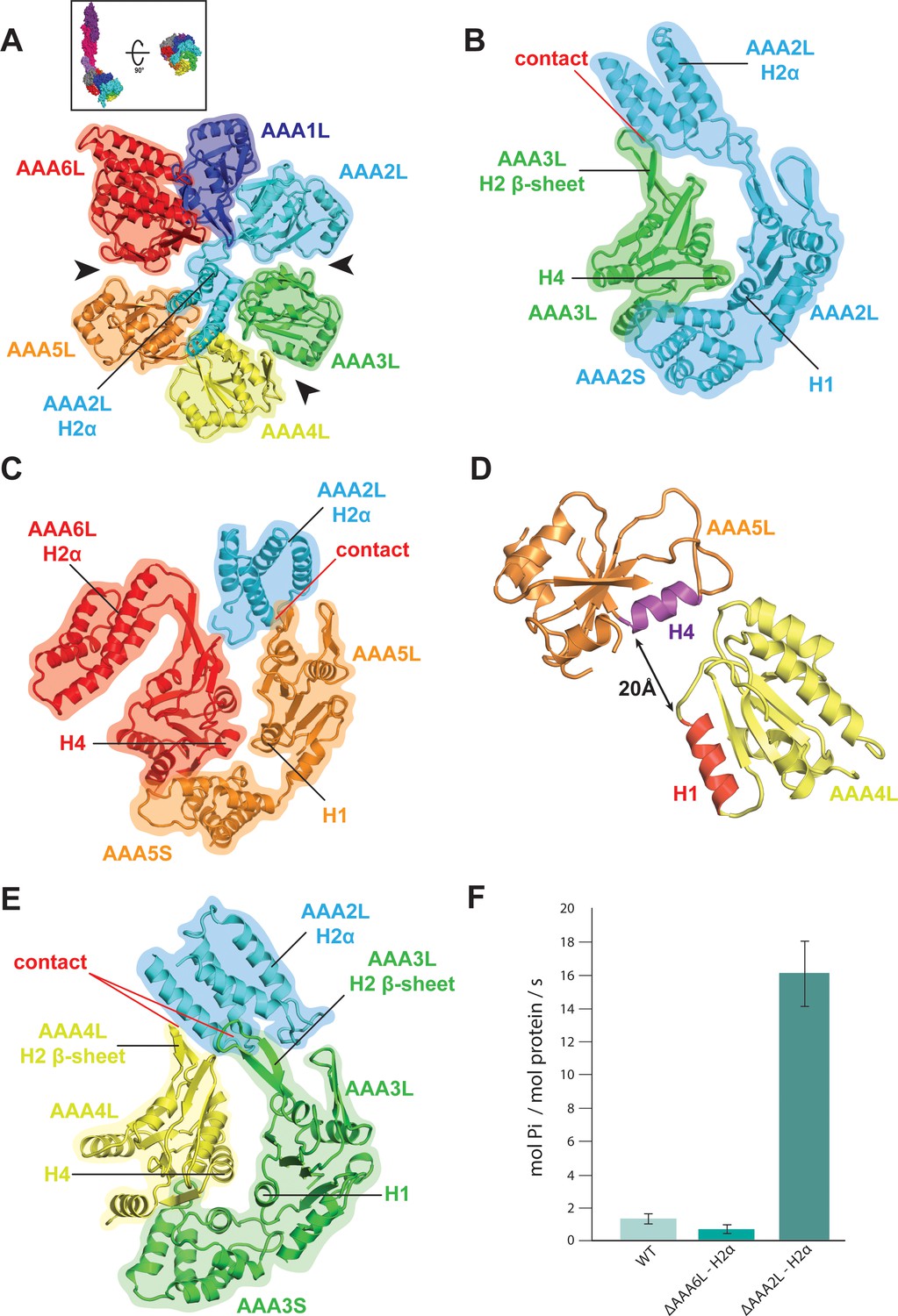
Rea1 AAA+ ring architecture and regulation of its ATPase activity.
(A) Architecture of the Rea1 AAA+ ring. For clarity, only AAAL domains are shown. Gaps exits between AAA2L/AAA3L, AAA3L/AAA4L and AAA5L/AAA6L (black arrows) indicating that nucleotide binding sites AAA2, AAA3 and AAA5 are open. The cartoon in the upper box establishes the view with respect to Figure 1C left panel. (B) Open AAA2 and (C) open AAA5 nucleotide-binding sites. In both cases, contacts between AAA2L-H2α and the AAA3L or AAA5L H2 β-sheets prevent site closure. (D) AAA4L is rotated with respect to AAA5L (see main text). The rotation moves its ATP-binding H1 α-helix (red) away from the AAA5L H4 α-helix (purple), which carries the R-finger to support ATP-hydrolysis at the AAA4 nucleotide site. The distance is indicated by the black arrow. For clarity parts of AAA5L and AAA4L are not shown. (E) Open AAA3 nucleotide-binding site. The gap between AAA3L and AAA4L is stabilized by contacts between AAA2L-H2α and the H2 β-sheets of AAA3L and AAA4L. (F) ATPase rates for wild type Rea1 (WT) and the AAA6L-H2α (ΔAAA6L-H2α) as well as AAA2L-H2α (ΔAAA2L-H2α) deletion mutants. Deleting AAA6L-H2α decreases the Rea1 ATPase rate, while deleting AAA2L-H2α leads to a 10–15-fold increase in ATPase activity.
Figure 2—figure supplement 1
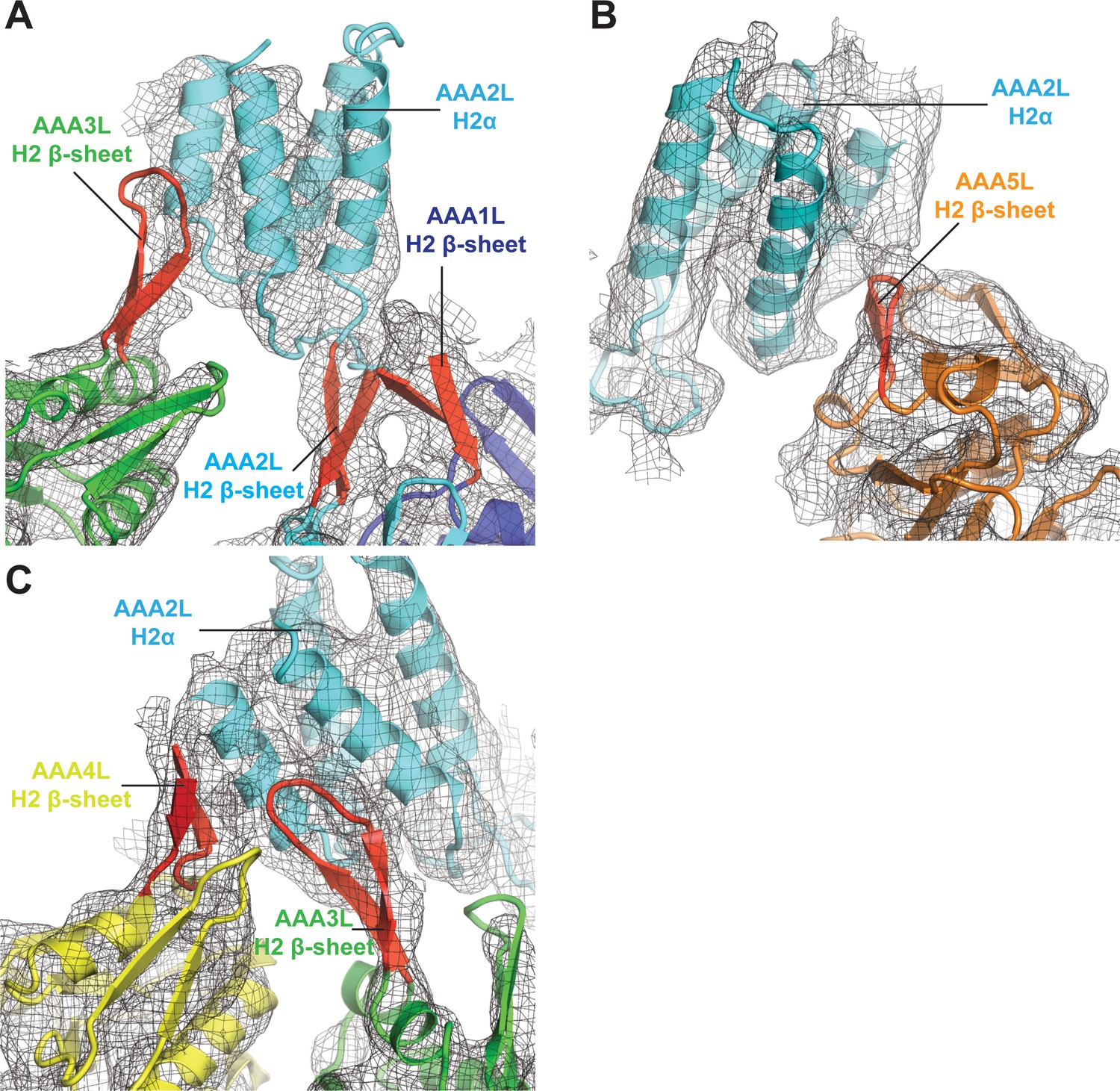
Interactions of AAA2L-H2α insert with H2 β-sheets of AAA1L, AAA3L, AAA4L, and AAA5L.
(A) The AAA2L H2 β-sheet interacts with the AAA1L H2 β-sheet. AAA2L-H2α contacts the tip of the AAA3L H2 β-sheet to keep the AAA2 site open. (B) AAA2L-H2α also contacts the tip of the AAA5L H2 β-sheet to stabilise the open AAA5 site. (C) AAA2L-H2α stabilises the open AAA3 nucleotide-binding site by contacting the AAA3L and AAA4L H2 β-sheets. AAA2L-H2α contacts the full length of the AAA4L H2 β-sheet and enforces a rotation of AAA4L (see main text). Only the β-sheet part of the AAA4L-H2α insert is visible. Its α-helical bundle cannot be assigned in the map. All H2-β-sheets are shown in red.
Figure 2—figure supplement 2

Rea1 AAA+ ring conformation and its comparison with dynein.
(A) In the Rea1 AAA+ ring, the H3 α-helices of AAA1L, AAA2L, AAA3L, AAA5L and AAA6L (red) point towards the pore of the AAA+ ring. The orientation of AAA4L (yellow) deviates from the orientation of the other AAA+ domains in the ring. It is rotated towards AAA5L as indicated by its H3 α-helix that points towards AAA5L rather than the AAA+ ring centre. For clarity only the AAAL domains of the AAA+ ring are shown and all inserts have been removed. (B) Comparison of Rea1 AAA+ ring with the ring of a dynein crystal structure in the ADP state. For clarity, only the AAAL domains are shown. Left panel: In Rea1, the AAA1L, AAA2L and AAA6L domains are more tightly associated and form one half of the AAA+ring. AAA3L, AAA4L, and AAA5L form the more loosely associated second half. The AAA1L-AAA2L + AAA6L domain block is separated from the AAA3L-AAA5L block by large gaps between AAA2L and AAA3L as well as AAA6L and AAA5L (black arrow heads). The internal organisation of the AAA3L-AAA5L half is characterised by the gap between AAA3L and AAA4L (grey arrow head), as well as the rotation of AAA4L towards AAA5L (both domains are shown in grey, with red H3 helices to indicate their relative orientation with respect to each other). Right panel: The dynein AAA+ ring (PDB-ID: 3VKG) is highly similar. Here, AAA2L-AAA4L form the more tightly packed first half of the ring. The weaker packed second half consists of AAA5L-AAA6L + AAA1L. Large gaps (black arrow heads) separate the two halves. The internal organisation of the second half is characterised by a gap between AAA5L and AAA6L (grey arrow head) and the rotation of AAA6L towards AAA1L (both highlighted in grey with H3 helices in red to indicate the orientation of AAA6L towards AAA1L).
Figure 3 with 1 supplement
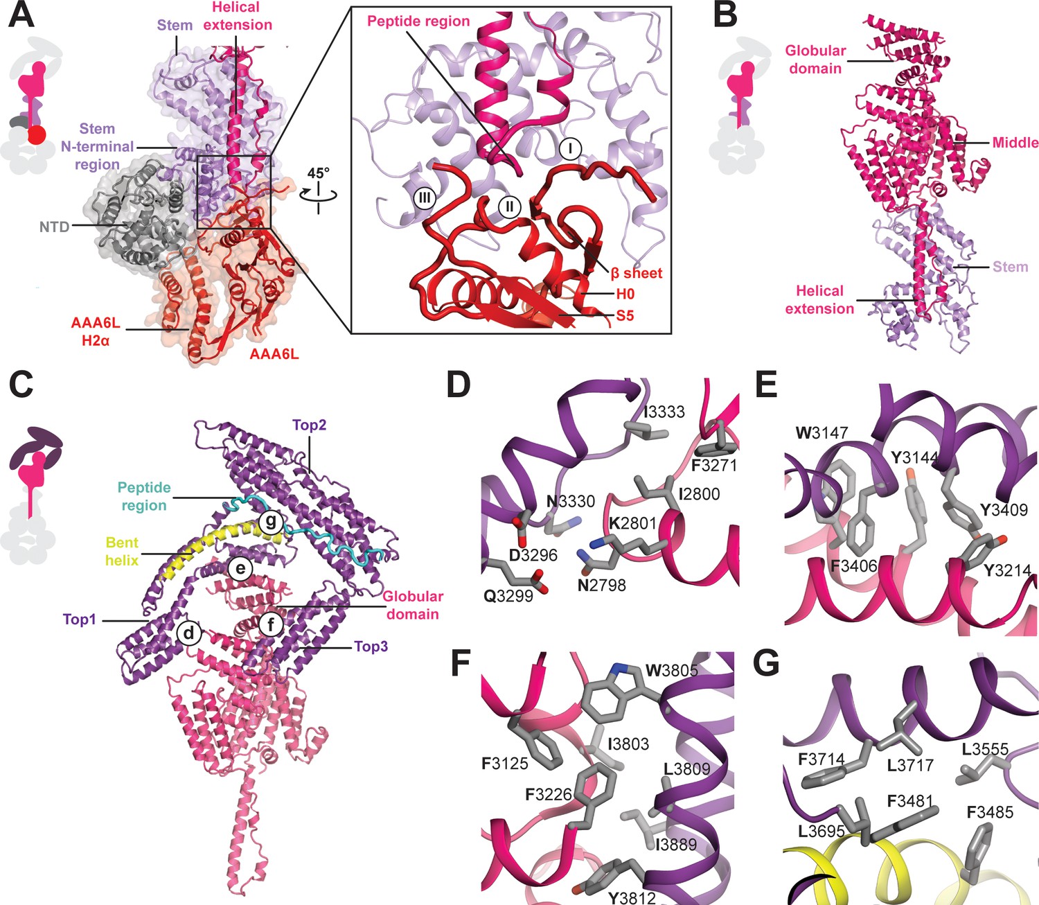
Architecture of the Rea1 linker.
(A) The AAA+ ring linker interface. Left panel: The N-terminal domain (NTD) acts as a scaffold between AAA6L and the linker stem via interactions with AAA6L-H2α and the N-terminal linker stem region. Right panel: Enlarged view of the AAA6L linker interactions. A β-sheet of AAA6L packs against the linker stem. AAA6L is also contacted by an α-helical extension of the linker middle domain. A short peptide region at its tip interacts with: (I) the loop leading to the AAA6L β-sheet, (II) the loop connecting this β-sheet to AAA6L H0 and (III) the loop connecting AAA6L S5 to the linker stem. (B) Linker middle domain featuring an α-helical as well as a globular extension. (C) The middle domain stabilises the architecture of the linker top. (D) Middle domain core and linker top1 interact through charged and hydrophobic residues. The interfaces between the middle domain globular extension and (E) top1, as well as (F) top3, are mainly hydrophobic. (G) Hydrophobic residues dominate the interface between top1 and top2. Top1 features a bent α-helix (yellow) and its connection to top2 is established via a long peptide region (cyan).
Figure 3—figure supplement 1
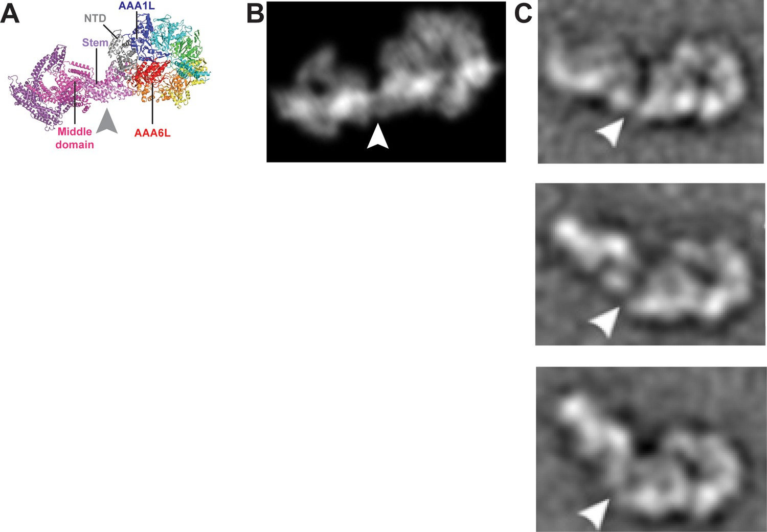
Remodelling of the Rea1 linker with respect to the AAA+ ring.
(A) The Rea1 ADP cryoEM structure. (B) 2D projection of the structure shown in A, and low pass filtered to 18 Å. (C) Top to bottom: Negative stain electron microscopy 2D classes of Rea1 published by Ulbrich et al. (2009). The linker appears to be in different conformations and is remodelled with respect to the AAA+ ring at a hinge region indicated by the white arrowheads. The view onto the AAA+ ring in the top panel is highly similar to the views in A and B. Comparing the (C) top panel to (A) and (B) suggests the area between linker stem and middle domain (grey arrowhead) as the hinge region.
Figure 4 with 6 supplements
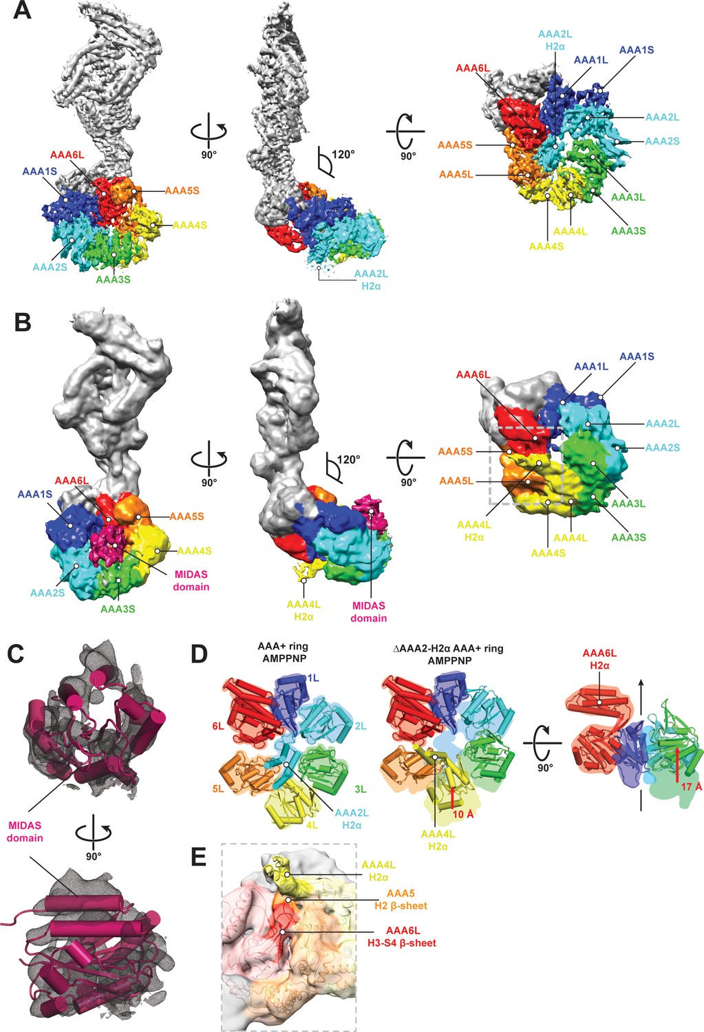
CryoEM structures of the Rea1 and Rea1_ΔAAA2L-H2α AMPPNP states.
(A) Front (left panel) and side (middle panel) view of the Rea1 AMPPNP state. The relative orientation of the linker with respect to the AAA+ ring has not changed. The AAA2L-H2α insert sits in the middle of the AAA+ ring (right panel), (B) Front (left panel) and side (middle panel) view of the Rea1_ΔAAA2L-H2α AMPPNP state. The angle between the linker and the AAA+ ring remains at 120°. A cryoEM density consistent with a MIDAS domain is visible above the AAA2S and AAA3S domains. The density for AAA2L-H2α has disappeared and the AAA4L-H2α insert is visible in the middle of the AAA+ ring (right panel) (C) Enlarged view of the MIDAS domain density demonstrating the fit with the integrin alpha-L MIDAS domain (purple cartoon, PDB-ID: 1T0P). Upper panel: front view, lower panel: side view. (D) Side-by-side comparison of the AAA+ rings of the Rea1 (left panel) and the Rea1_ΔAAA2L-H2α (middle and right panel) AMPPNP states. For clarity, only the AAAL domains (cartoon representation) are shown. The colour-coded outline of the AAAL positions of the Rea1 AMPPNP state (left panel) is superimposed on the AAAL positions of the Rea1_ΔAAA2L-H2α AMPPNP state (middle and right panels). For the right panel, AAA4L, and AAA5L were removed to better demonstrate the shift of AAA3L. The black arrow runs through the ring centre and indicates the direction towards the H2α insert side of the ring. Red arrows indicate the shift of the AAAL core. (E) Side view of the area marked by the grey dotted box of the right panel in (B) in transparent surface and cartoon representation. The AAA4L-H2α insert is in close proximity to the AAA5L H2 β-sheet and the AAA6L H3-S4 H2-β-sheet.
Figure 4—figure supplement 1
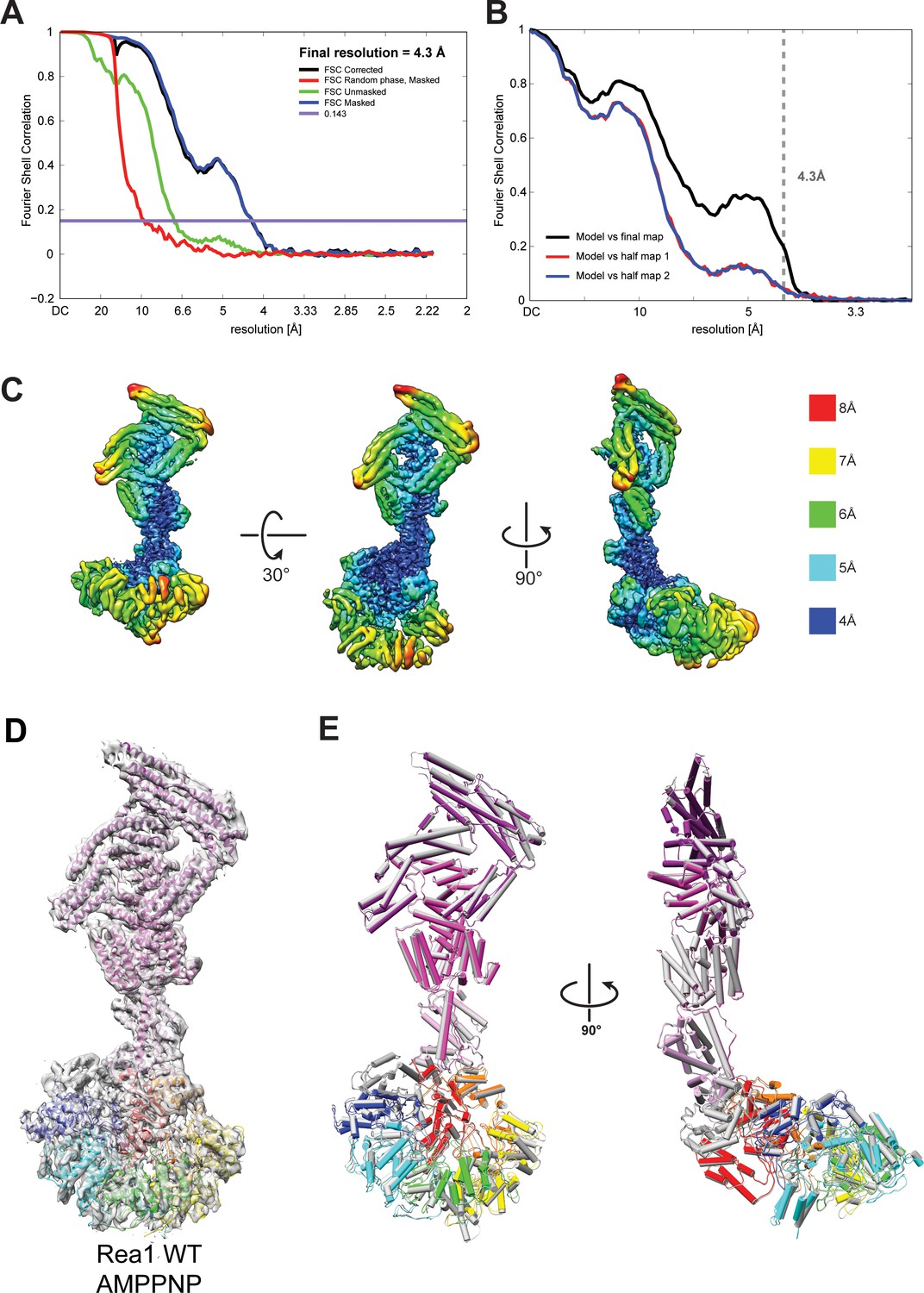
Quality of the Rea1 AMPPNP map and comparison of the Rea1 ADP and AMPPNP structures.
(A) Fourier shell correlation (FSC) plot for half-maps of the Rea1 AMPPNP reconstruction. The 0.143 FSC criteria is indicated as horizontal blue line. The final overall resolution is 4.3 Å. (B) Model vs map FSC curves for the final Rea1 AMPPNP model versus the final Rea1 AMPPNP map. (C) Local resolution of the Rea1 AMPPNP reconstruction. (D) The final Rea1 AMPPNP model docked into the cryoEM map. (E) Alignment of the Rea1 AMPPNP (colour coded) and Rea1 ADP (grey) structures. Left panel: front view, right panel: side view. The two structures are largely identical.
Figure 4—figure supplement 2

Negative stain electron microscopy reconstructions of Rea1 APO and ATP states.
(A) Front (left panel) and side view (right panel) of the Rea1 APO state. The angle between the linker and the AAA+ ring (red) is marked on right panel. It remains around 120° like in the Rea1 ADP structure. (B) Front (left panel) and side view (right panel) of the Rea1 ATP state. The angle between the linker and AAA+ ring has not changed.
Figure 4—figure supplement 3

Negative stain electron microscopy reconstructions of Rea1_ΔAAA2L-H2α APO, AMPPNP, ATP and ADP states.
The left panels represent the front views and the right panels the side views of the (A) APO, (B) AMPPNP, (C) ATP and (D) ADP states of the Rea1_ΔAAA2L-H2α deletion mutant. The angle between the linker and the AAA+ ring (red) is marked at the right panel of (A). It remains around 120° in all investigated states indicating that also Rea1_ΔAAA2L-H2α does not undergo nucleotide depended large scale linker remodelling. The APO and AMPPNP states shown in (A) and (B) have an additional density that extends from the AAA+ ring (red arrows).
Figure 4—figure supplement 4
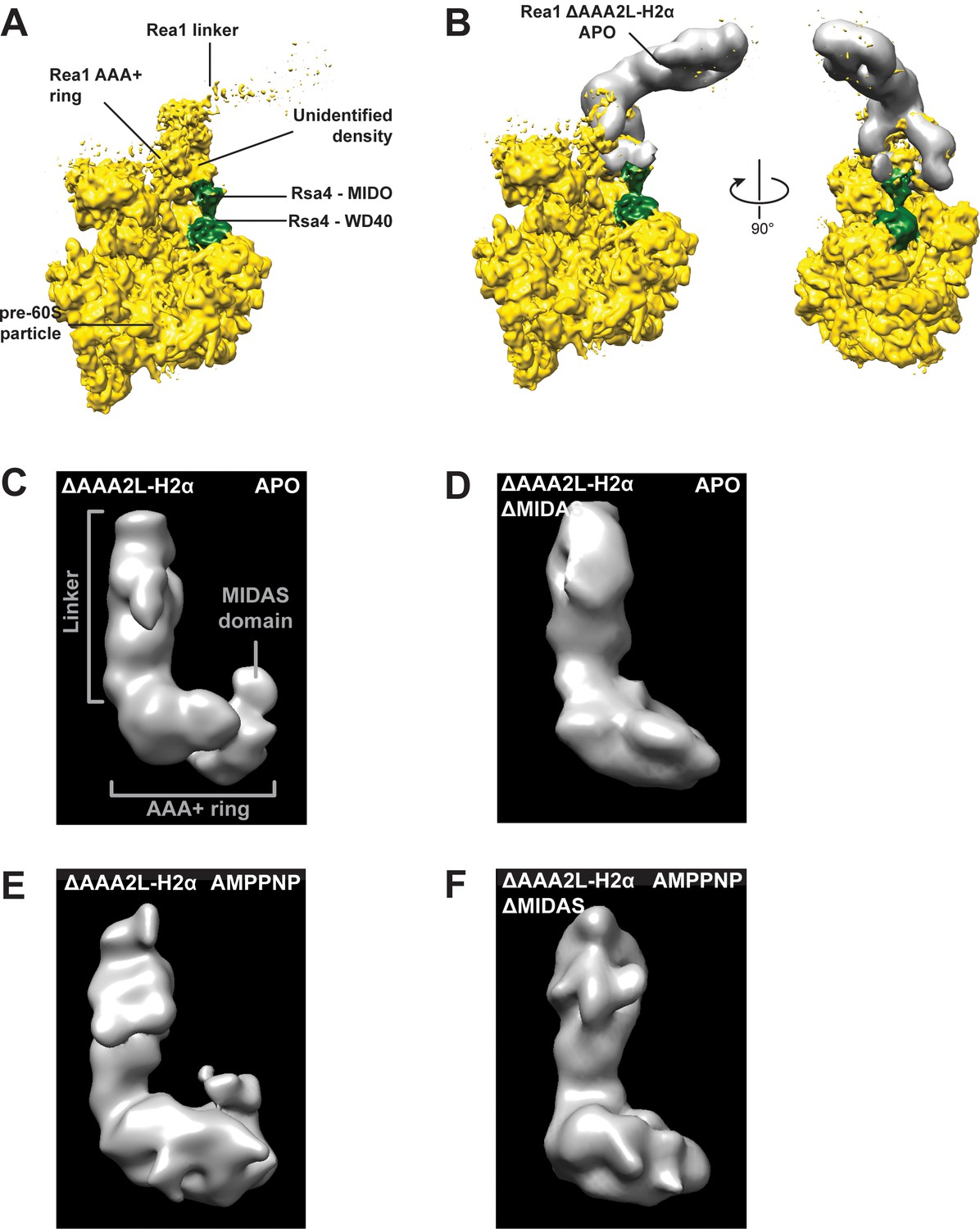
The additional density at the AAA+ ring of the Rea1_ΔAAA2L-H2α APO and AMPPNP states is the MIDAS domain.
(A) A recently published cryoEM structure of a complex between Rea1 and an Rsa4 containing pre60S particle revealed the location of the Rea1 AAA+ ring on the pre60S particle. The Rea1 linker was flexible with respect to the AAA+ ring as indicated by its weaker density. It also revealed the location of Rsa4 (green). An unidentified density was found to sit right above the Rsa4 MIDO domain. (B) Docking the AAA+ ring of Rea1_ΔAAA2L-H2α APO would place the additional AAA+ ring density directly above the Rsa4 MIDO domain into the so far unidentified density. This suggest that the extra density is the MIDAS domain. Left panel: side view, right panel: front view. (C) Side view of the negative stain electron microscopy reconstruction of the Rea1_ΔAAA2L-H2α APO state. (D) Side view of the negative stain electron microscopy reconstruction of the Rea1_ΔAAA2L-H2α_ΔMIDAS APO state. (E) Side view of the negative stain electron microscopy reconstruction of the Rea1_ΔAAA2L-H2α AMPPNP state. (F) Side view of the negative stain electron microscopy reconstruction of the Rea1_ΔAAA2L-H2α_ΔMIDAS AMPPNP state. Consistent with its interpretation as MIDAS domain, the extra density is not visible in D and F.
Figure 4—figure supplement 5
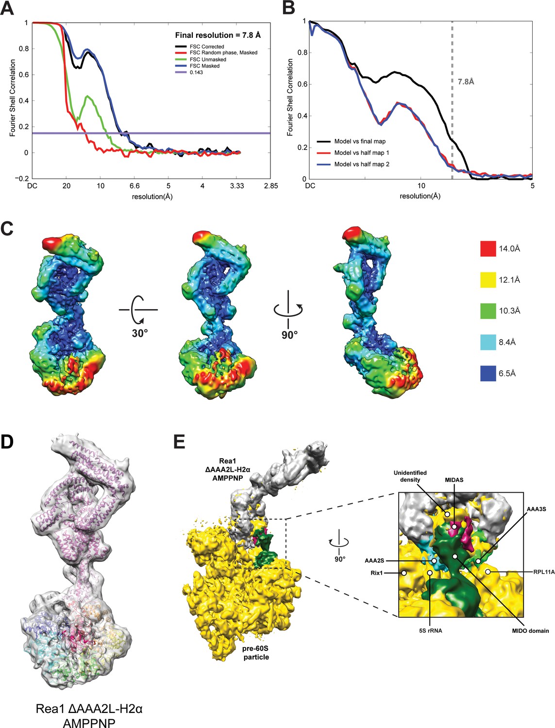
CryoEM structure of the Rea1_ΔAAA2L-H2α AMPPNP state.
(A) Fourier shell correlation (FSC) plot for half-maps of the Rea1_ΔAAA2L-H2α AMPPNP reconstruction. The 0.143 FSC criteria is indicated as horizontal blue line. The final overall resolution is 7.8 Å. (B) Model vs map FSC curves for the final Rea1_ΔAAA2L-H2α AMPPNP model versus the final Rea1_ΔAAA2L-H2α AMPPNP map. (C) Local resolution map of the Rea1_ΔAAA2L-H2α AMPPNP reconstruction. (D) The Rea1_ΔAAA2L-H2α AMPPNP model docked into the cryoEM map. (E) Docking of the Rea1_ΔAAA2L-H2α AMPPNP cryoEM map into the cryoEM map shown in Figure 4—figure supplement 4A would place the MIDAS domain density in direct contact with the MIDO domain of Rsa4. The AAA2S and AAA3S domains of the AAA+ ring contact the 5S rRNA and Rpl11A, respectively.
Figure 4—figure supplement 6
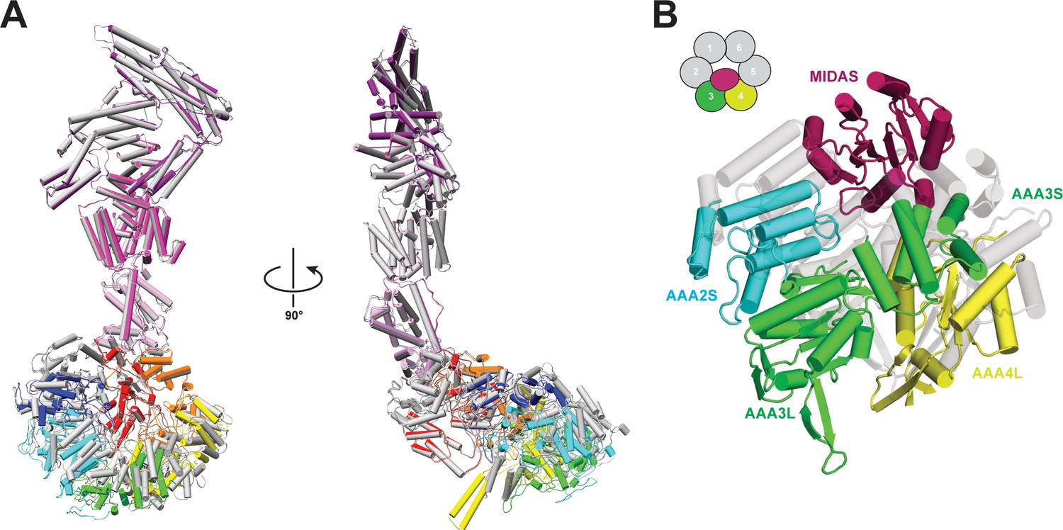
Comparison of Rea1 and Rea1_ΔAAA2L-H2α AMPPNP states.
(A) The Rea1_ΔAAA2L-H2α AMPPNP structure (colour coded) superimposed on the Rea1 AMPPNP structure (grey) Left panel: front view, right panel: side view. The superimposition was done by aligning the NTD, AAA1, AAA6 and the linker. Rearrangements are evident for the AAA2, AAA3, AAA4 and AAA5 modules. For clarity, the MIDAS domain has been removed (B) Conformational rearrangements leading to the creation of the MIDAS docking site. In the alignment shown in (A), the AAA3 and AAA4 modules, consisting of AAA3L/AAA2S and AAA4L/AAA3S, have moved to create the MIDAS domain binding site above their AAA2S and AAA3S domains. The Rea1_ΔAAA2L-H2α AMPPNP structure is colour coded and the Rea1 AMPPNP structure is shown as transparent grey cartoon.
Figure 5
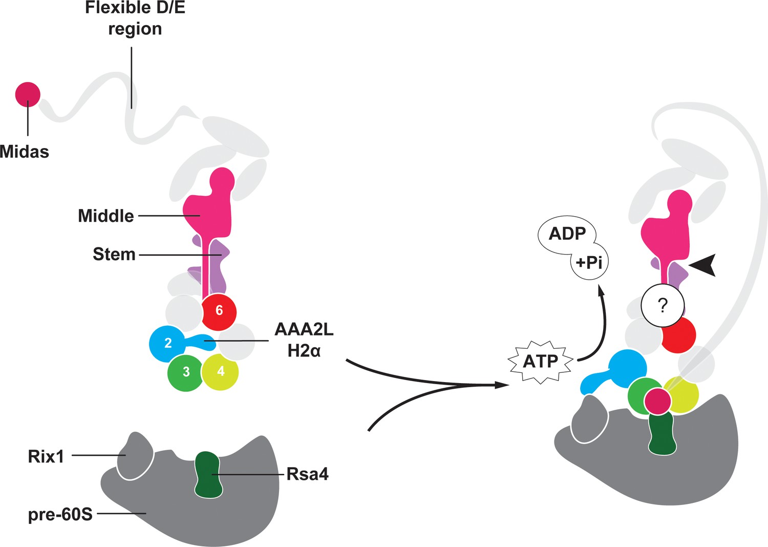
Model for Rea1 mediated Rsa4 assembly factor removal.
In the absence of pre60S particles the Rea1 ATP-hydrolysis activity is inhibited by AAA2L-H2α. When Rea1 binds to pre60S particles, AAA2L-H2α relocates towards Rix1, and the Rea1 ATPase activity is stimulated. AAA2L-H2α removal allows nucleotide dependent conformational changes in the ring that cause a shift in the positions of the AAA3 and AAA4 modules and result in the recruitment of the MIDAS domain. The AAA+ ring binding site brings the MIDAS domain in close contact with its Rsa4 substrate. AAA6L of the AAA6 module has the ideal position to communicate ATP-dependent conformational changes of ring into the linker via its interface with the linker stem and the helix extension of the linker middle domain. The interface between linker stem and middle domain (black arrow head) might act as a pivot point during linker remodelling. The rearrangement of the linker during remodelling, and how it produces force to remove the Rsa4 engaged MIDAS domain from the AAA+ ring remains unknown (question mark).
Tables
Key resources table
| Reagent type (species) or resource | Designation | Source or reference |
|---|---|---|
| Strain, strain background (S. cerevisae) | JD1370 | DOI: 10.1126/science.1212642 |
| Chemical compound | 1,4-dithiotreitol (DTT) | Thermo Fisher SCIENTIFIC |
| Chemical compound | ATP | ACROS Organics |
| Chemical compound | AMPPNP | Jena biosciences |
| Chemical compound | ADP | SIGMA-ALDRICH |
| Chemical compound | Roche cOmplete, EDTA-free Protease Inhibitor | SIGMA-ALDRICH |
| Chemical compound | Dimethylsulfoxide (DMSO) | SIGMA-ALDRICH |
| Chemical compound | Phenylmethylsulfonyl fluoride (PMSF) | SIGMA-ALDRICH |
| Chemical compound | Yeast Nitrogen Base without Amino acids | Formedium |
| Chemical compound | D(+) - Glucose | Formedium |
| Chemical compound | D(+) - Galactose | Formedium |
| Chemical compound | CSM, -Ura | Formedium |
| Chemical compound | Triton X-100 | SIGMA-ALDRICH |
| Commercial assay or kit | EnzChek Phosphate Assay Kit | Thermo Fisher SCIENTIFIC |
| Software, algorithm | Adobe Photoshop version 16.0.3 (for figure preparation) | Adobe Systems, Inc. N/A |
| Software, algorithm | PyMOL(TM) 2.0.6 Schrodinger LLC | https://pymol.org/edu/?q=educational/ |
| Software, algorithm | Chimera Pettersen et al., 2004 | https://www.cgl.ucsf.edu/chimera/download.html |
| Software, algorithm | Gautomatch | https://www.mrc-lmb.cam.ac.uk/kzhang/Gautomatch/ |
| Software, algorithm | Serial EM Mastronarde, 2005 | http://bio3d.colorado.edu/SerialEM |
| Software, algorithm | MotionCor2Zheng et al., 2017 | http://msg.ucsf.edu/em/software/motioncor2.html |
| Software, algorithm | RELION 2.0 Kimanius et al., 2016 | http://www2.mrc-lmb.cam.ac.uk/relion |
| Software, algorithm | COOT Emsley and Cowtan, 2004 | http://www2.mrc-lmb.cam.ac.uk/personal/pemsley/coot |
| Software, algorithm | PHENIX Adams et al., 2010 | https://www.phenix-online.org |
Additional files
-
Supplementary file 1
Data collection and refinement statistics.
Data collection and refinement statistics for the presented cryoEM maps and structural models. VPP = volta phase plate.
- https://doi.org/10.7554/eLife.39163.023
-
Transparent reporting form
- https://doi.org/10.7554/eLife.39163.024
Download links
A two-part list of links to download the article, or parts of the article, in various formats.
Downloads (link to download the article as PDF)
Open citations (links to open the citations from this article in various online reference manager services)
Cite this article (links to download the citations from this article in formats compatible with various reference manager tools)
The CryoEM structure of the Saccharomyces cerevisiae ribosome maturation factor Rea1
eLife 7:e39163.
https://doi.org/10.7554/eLife.39163


