Author Contributions
The work presented in this paper is the output of an Innovate UK research project, HiTEV, jointly undertaken by The University of Sheffield and Nissan Technical Centre Europe. Z.Q.Z., D.A.S., M.P.F., and B.B. are the project investigators, while H.Q., J.R., T.M., D.I., T.K., K.S., and J.G., are the project team members, all contributed to the FEA calculation, analyses, discussions and the paper writing. All authors have read and agreed to the published version of the manuscript.
Figure 1.
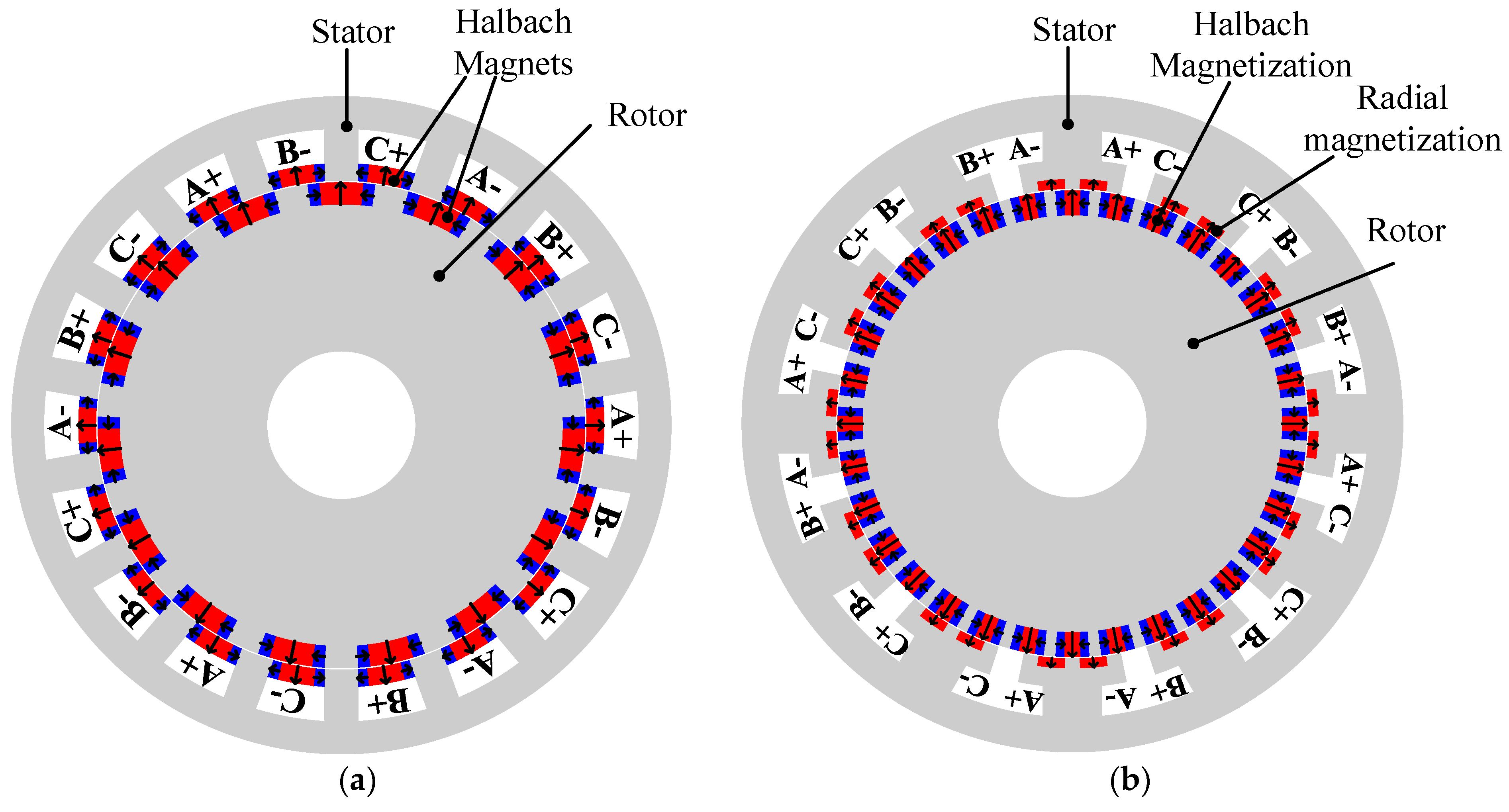
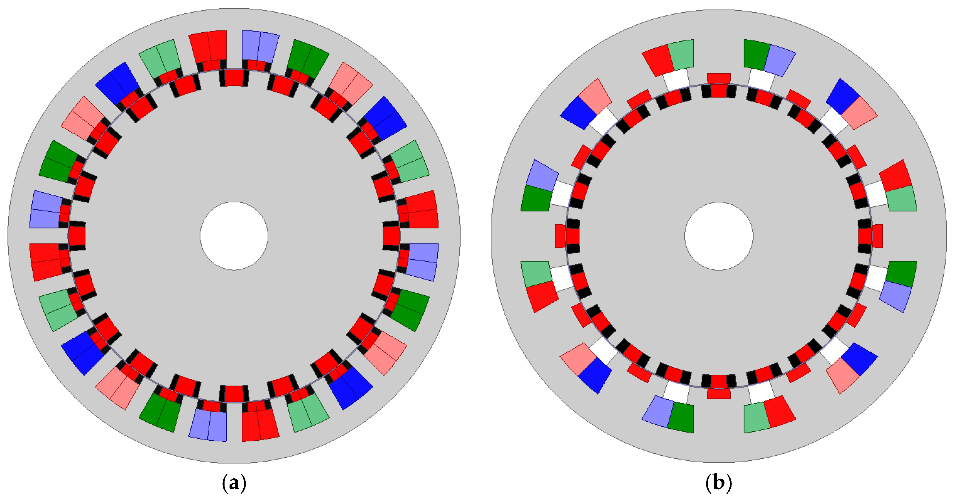
Machine topologies of dual permanent magnet (PM) machines. (a) 24S20R4Pa stator slot dual-PM (SSDPM) machine; (b) 12S20R4Pa split-tooth dual-PM (STDPM) machine.
Figure 1.
Machine topologies of dual permanent magnet (PM) machines. (a) 24S20R4Pa stator slot dual-PM (SSDPM) machine; (b) 12S20R4Pa split-tooth dual-PM (STDPM) machine.
Figure 2.
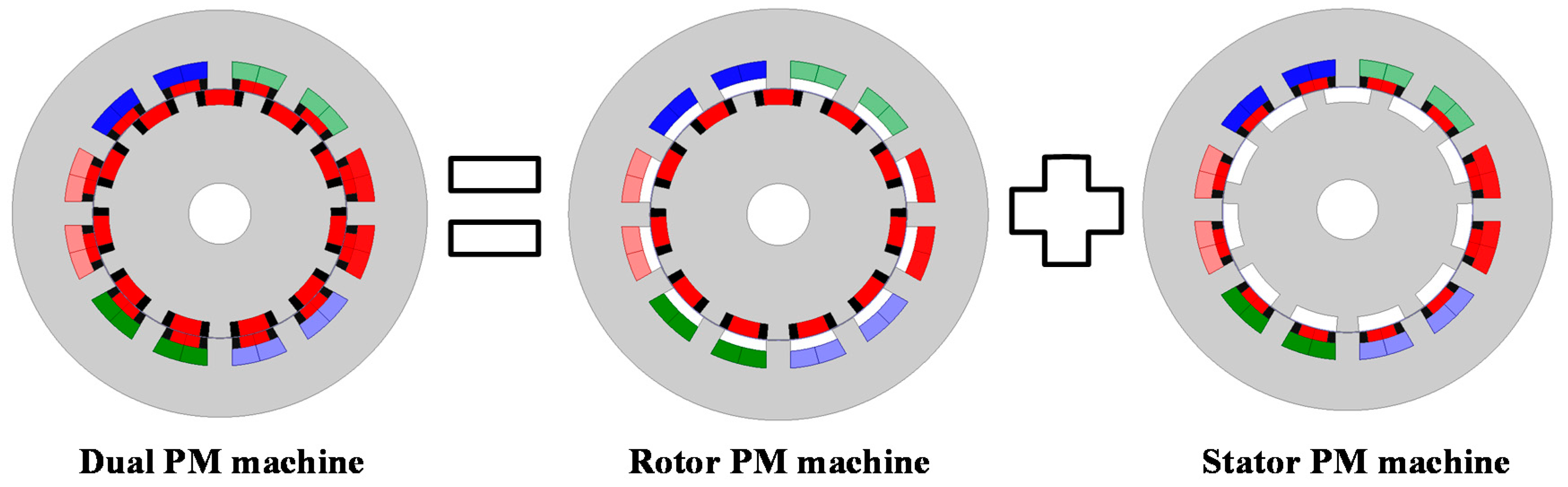
Machine decomposition of 12S11R1Pa SSDPM machine.
Figure 2.
Machine decomposition of 12S11R1Pa SSDPM machine.
Figure 3.
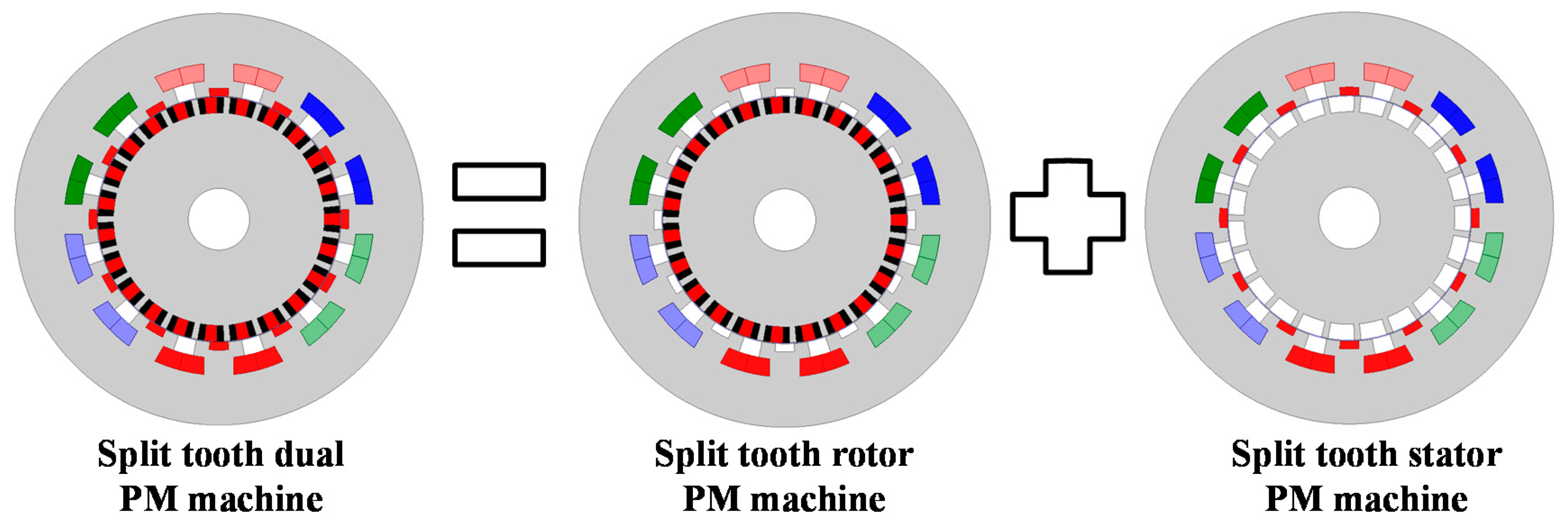
Machine decomposition of 12S23R1Pa STDPM machine.
Figure 3.
Machine decomposition of 12S23R1Pa STDPM machine.
Figure 4.
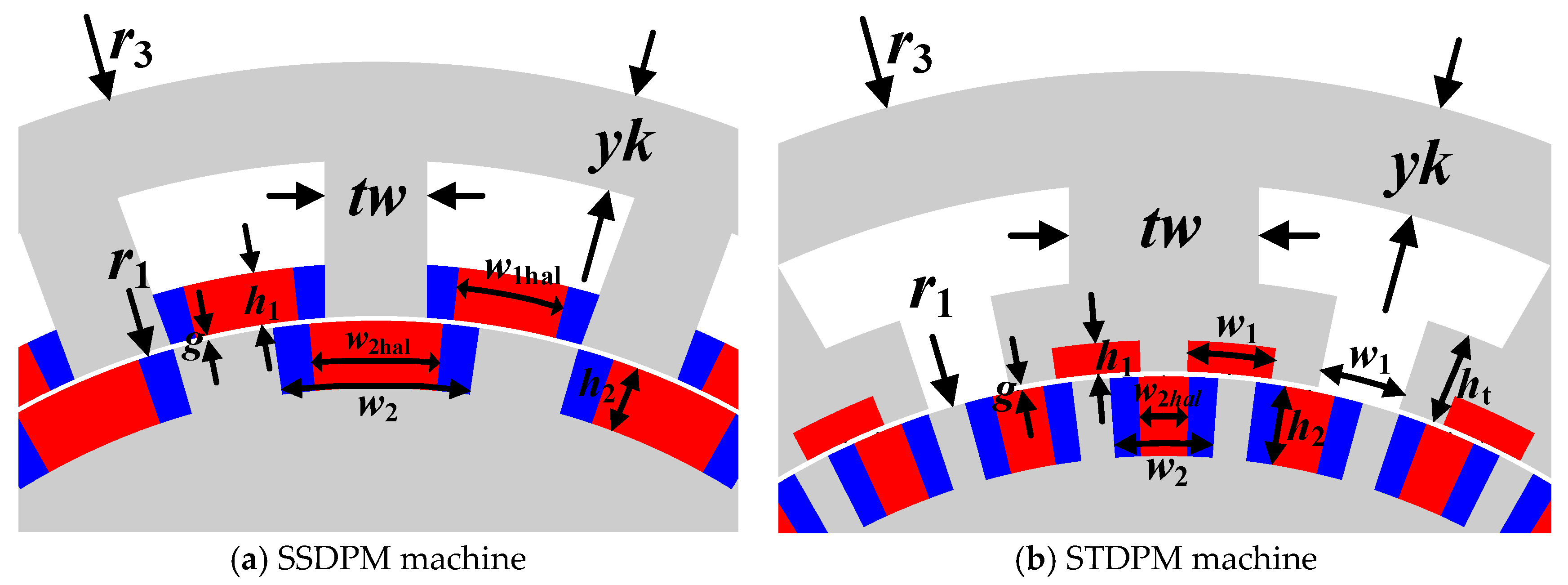
Key design dimensions of dual-PM machines. (a) SSDPM machine; (b) STDPM machine.
Figure 4.
Key design dimensions of dual-PM machines. (a) SSDPM machine; (b) STDPM machine.
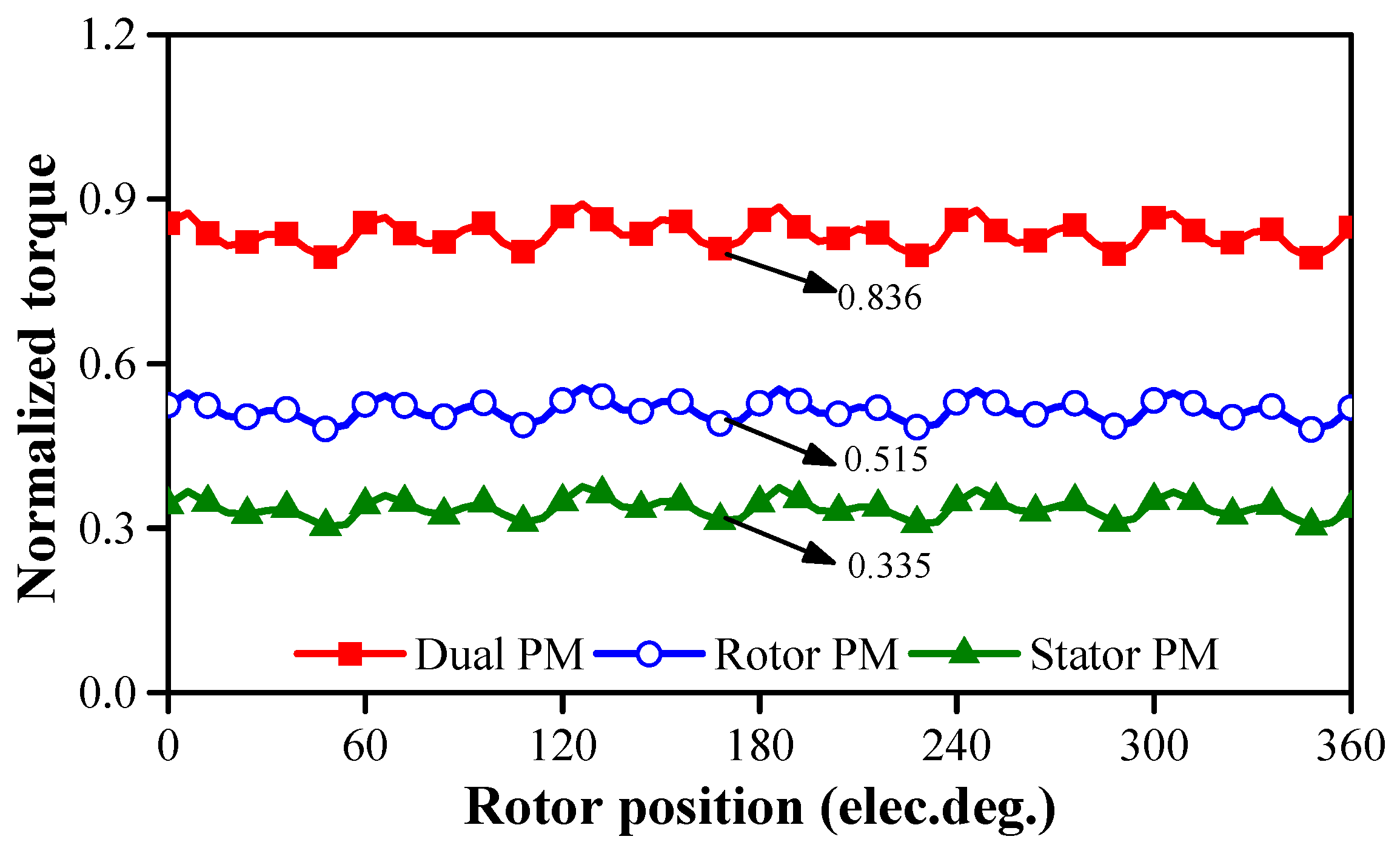
Figure 5.
Torque decomposition of 12S11R1Pa SSDPM machine when relative permeability is 50.
Figure 5.
Torque decomposition of 12S11R1Pa SSDPM machine when relative permeability is 50.
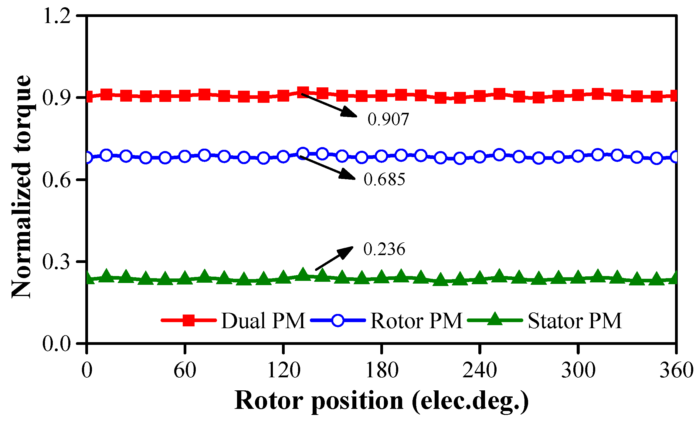
Figure 6.
Torque decomposition of 12S23R1Pa STDPM machine when relative permeability is 50.
Figure 6.
Torque decomposition of 12S23R1Pa STDPM machine when relative permeability is 50.
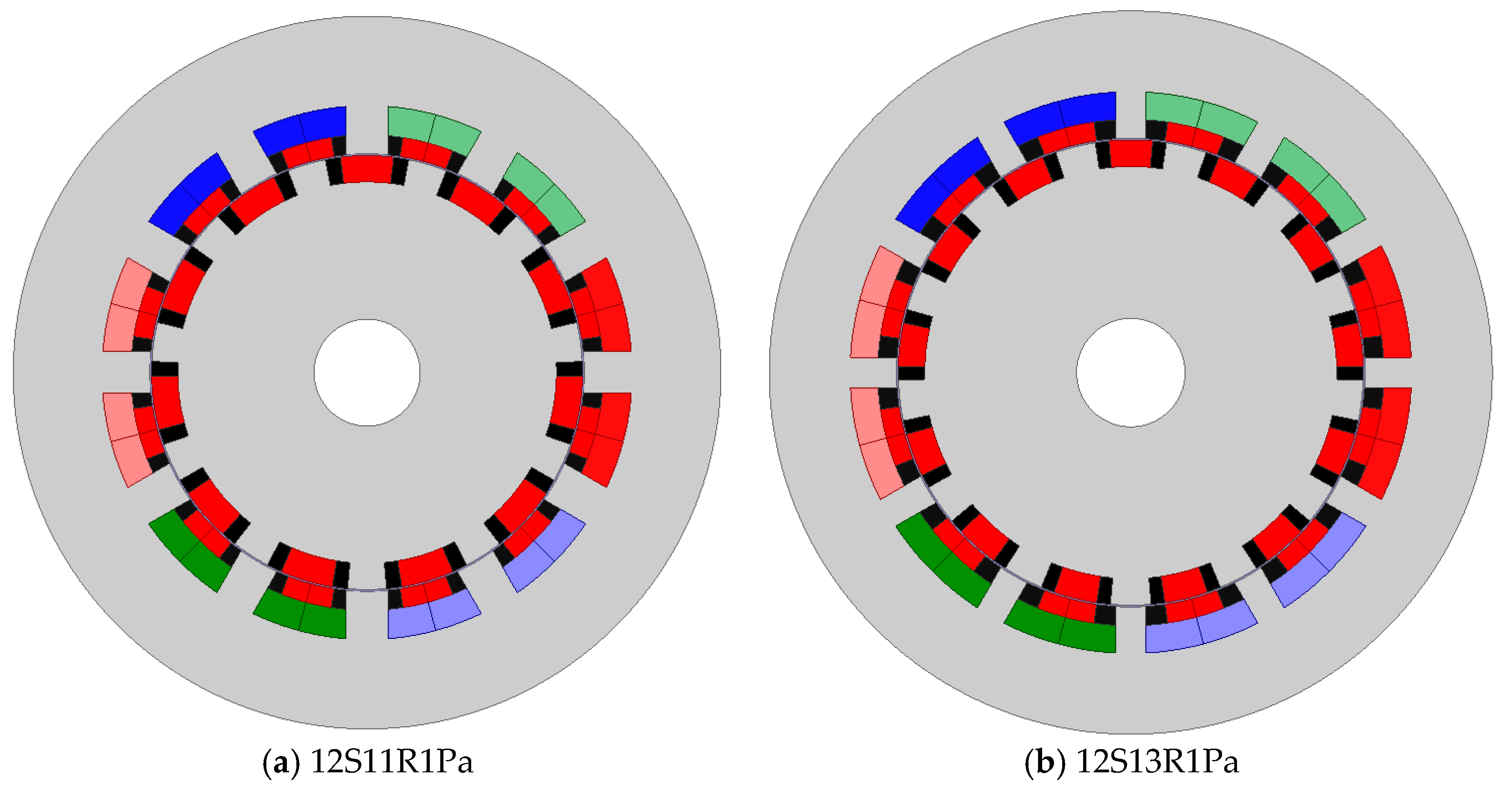
Figure 7.
Twelve-stator-slot SSDPM machines with a different rotor slot number. (a) 12S11R1Pa; (b) 12S13R1Pa.
Figure 7.
Twelve-stator-slot SSDPM machines with a different rotor slot number. (a) 12S11R1Pa; (b) 12S13R1Pa.
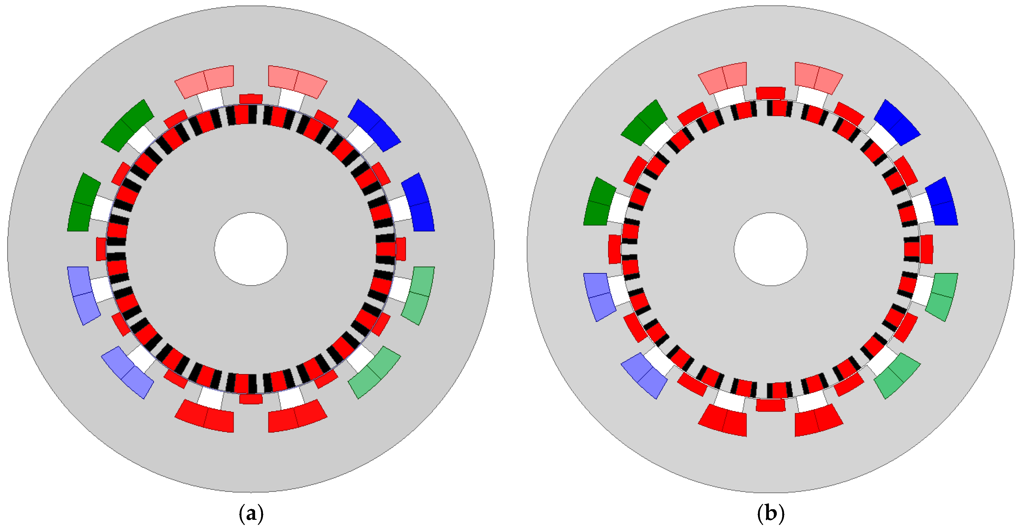
Figure 8.
Twelve-stator-slot STDPM machines with a different rotor slot number. (a) 12S23R1Pa; (b) 12S25R1Pa.
Figure 8.
Twelve-stator-slot STDPM machines with a different rotor slot number. (a) 12S23R1Pa; (b) 12S25R1Pa.
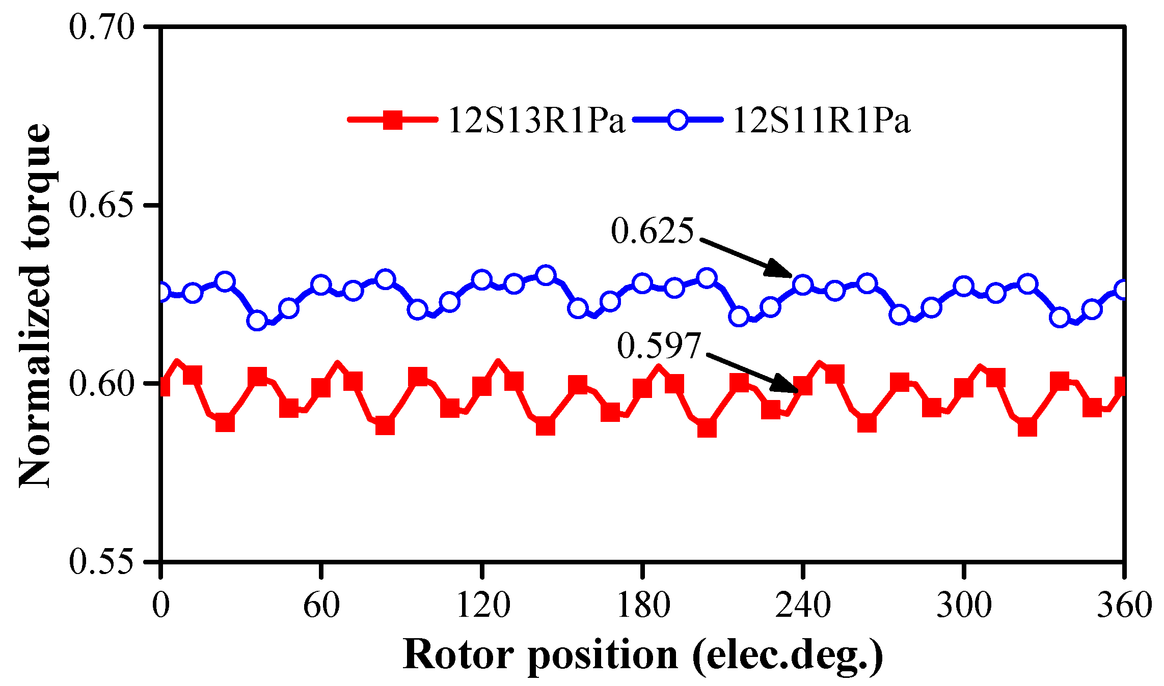
Figure 9.
Torque waveforms of 12S1Pa SSDPM machines.
Figure 9.
Torque waveforms of 12S1Pa SSDPM machines.
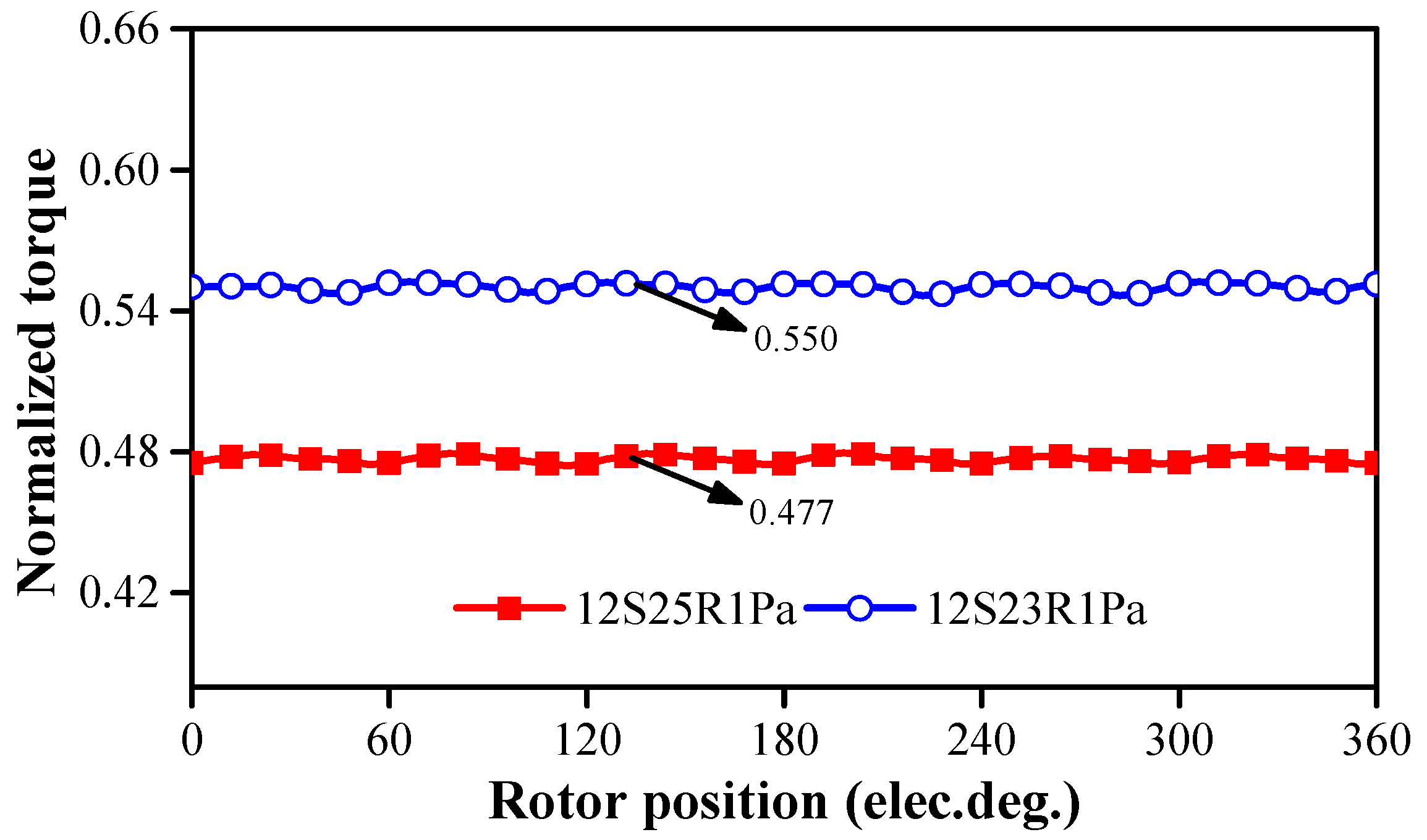
Figure 10.
Torque waveforms of 12S1Pa STDPM machines.
Figure 10.
Torque waveforms of 12S1Pa STDPM machines.
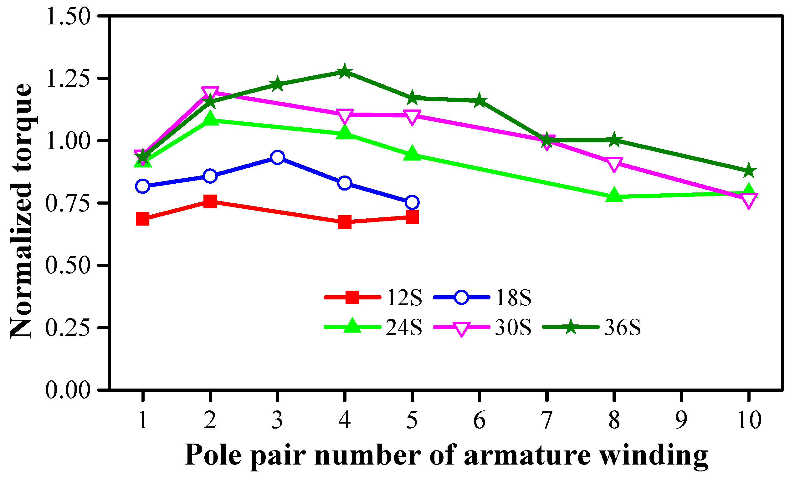
Figure 11.
Torques versus armature pole pair number and stator slot number when rotor slot number is selected as Ns − Pa.
Figure 11.
Torques versus armature pole pair number and stator slot number when rotor slot number is selected as Ns − Pa.
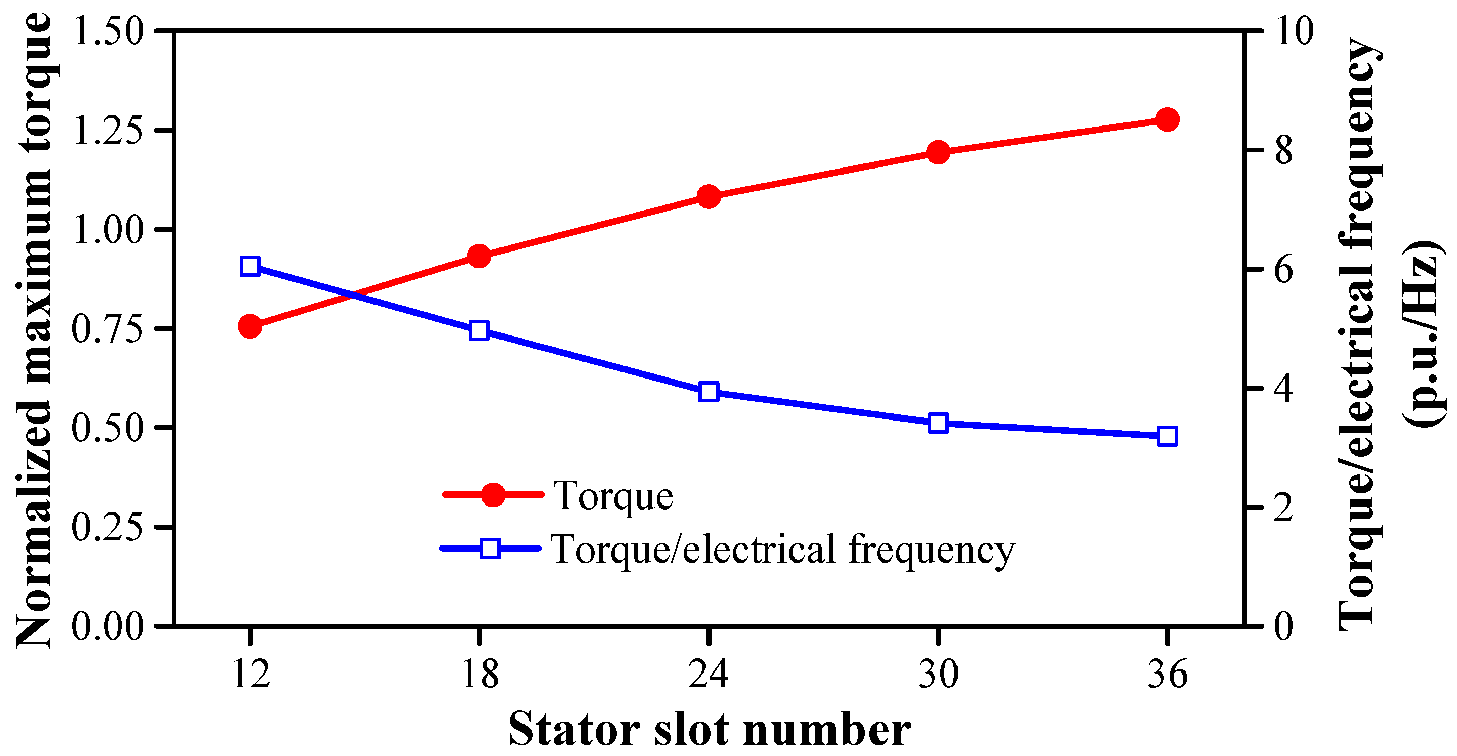
Figure 12.
Maximum torque and torque/electrical frequency versus stator slot number at 600 rpm.
Figure 12.
Maximum torque and torque/electrical frequency versus stator slot number at 600 rpm.
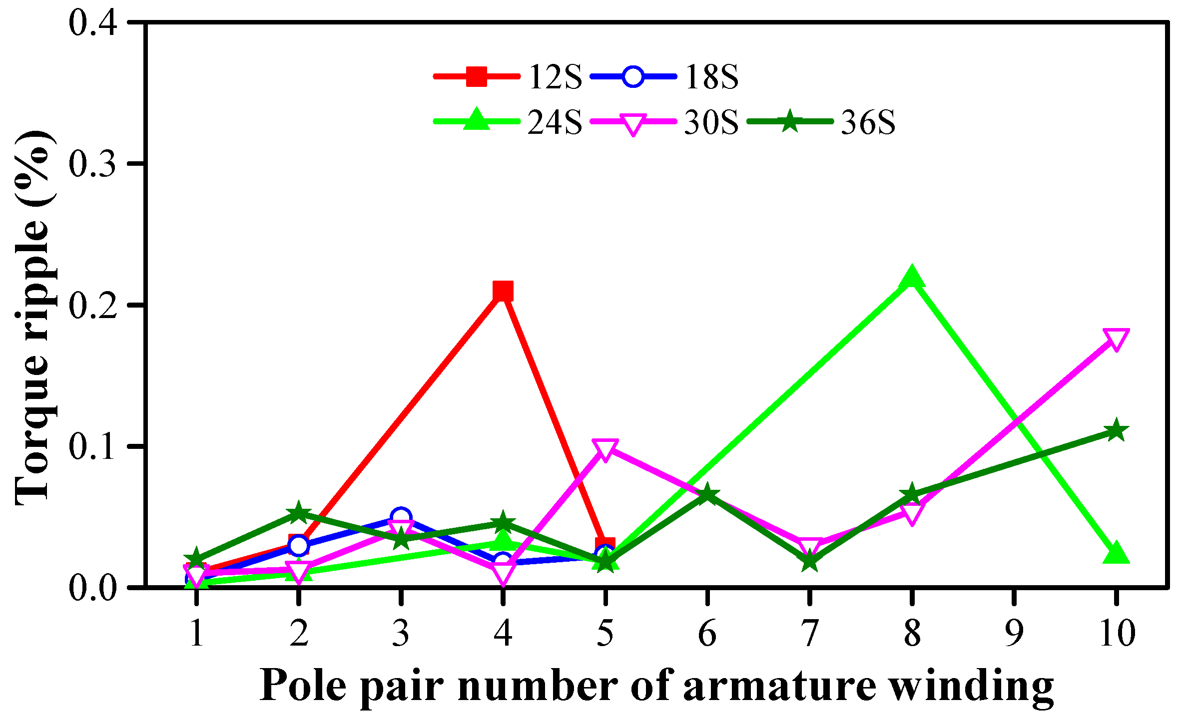
Figure 13.
Torque ripples versus armature pole pair number and stator slot number when rotor slot number is selected as Ns − Pa.
Figure 13.
Torque ripples versus armature pole pair number and stator slot number when rotor slot number is selected as Ns − Pa.
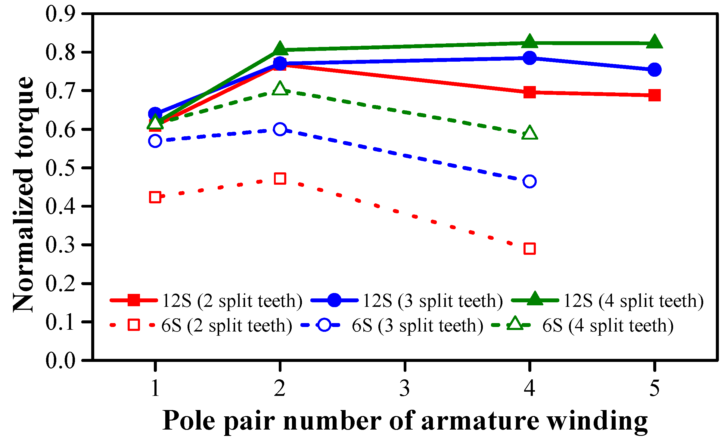
Figure 14.
Torques versus stator slot number, armature pole pair number, and split-tooth number when rotor slot number is selected as nNs − Pa.
Figure 14.
Torques versus stator slot number, armature pole pair number, and split-tooth number when rotor slot number is selected as nNs − Pa.
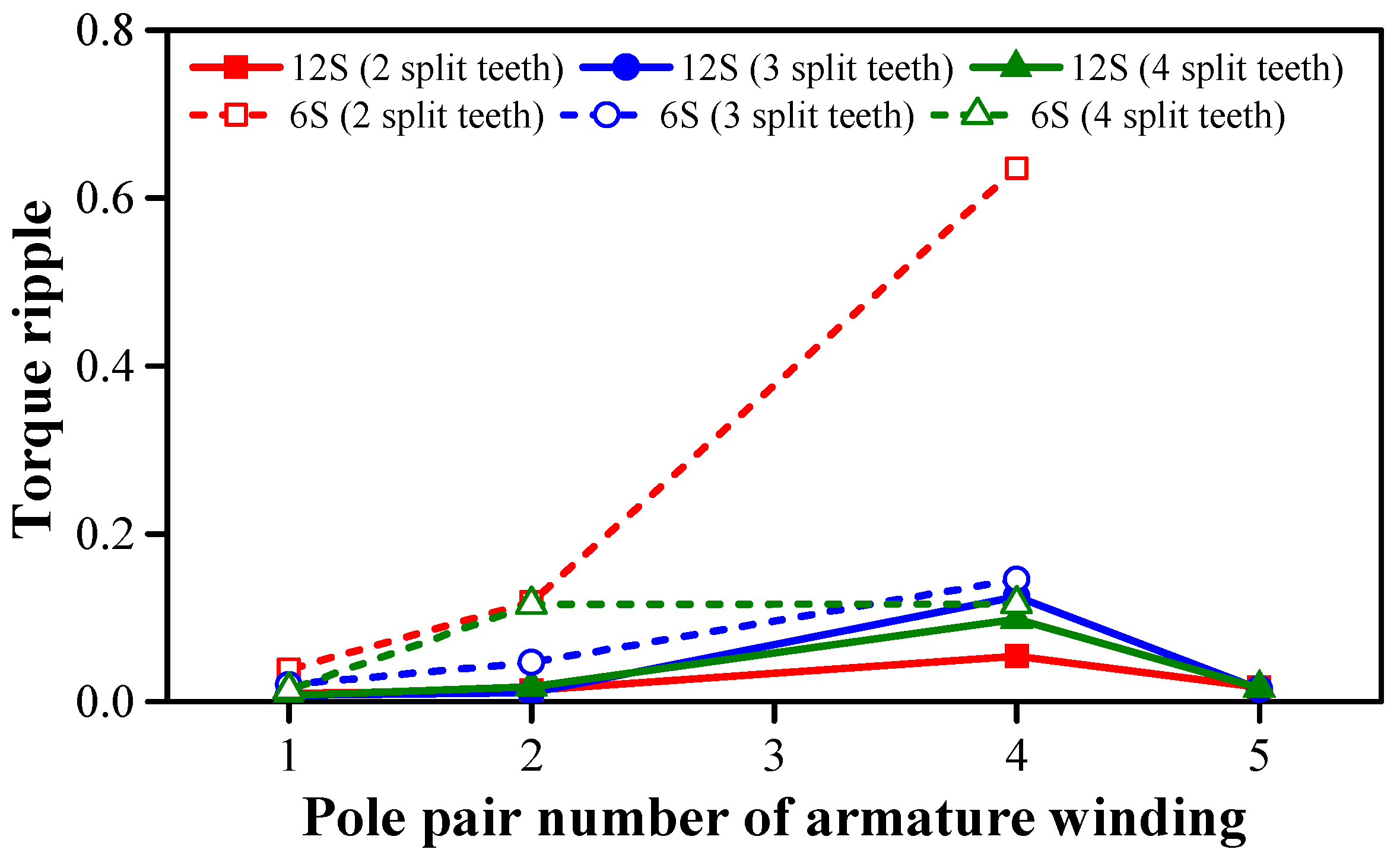
Figure 15.
Torque ripples versus stator slot number, armature pole pair number, and split-tooth number when rotor slot number is selected as nNs − Pa.
Figure 15.
Torque ripples versus stator slot number, armature pole pair number, and split-tooth number when rotor slot number is selected as nNs − Pa.
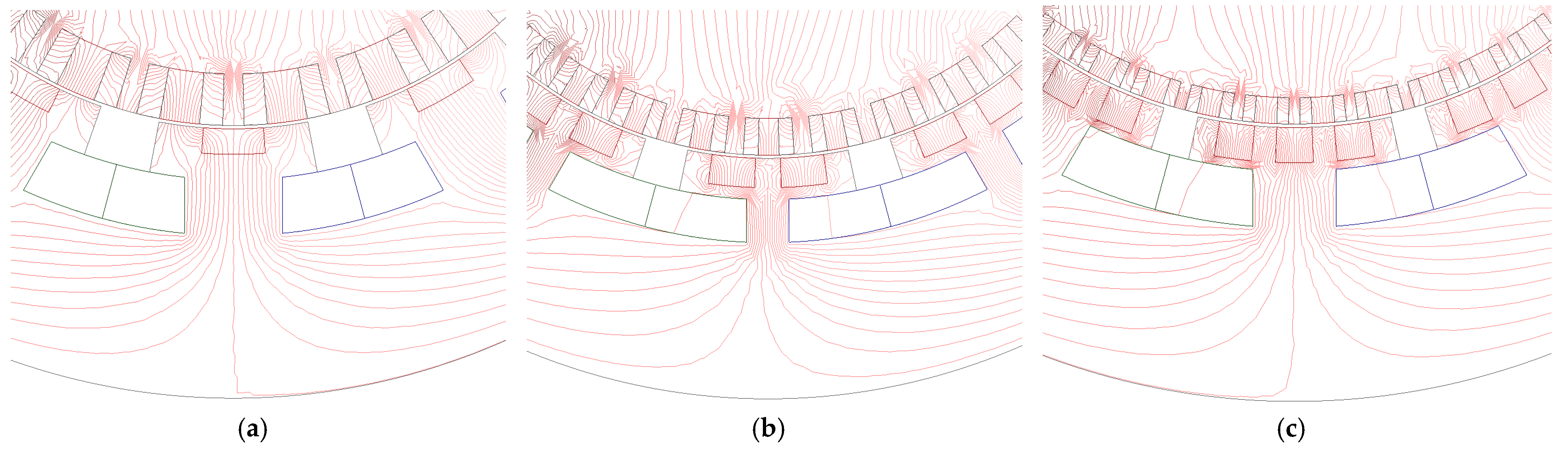
Figure 16.
Flux line distributions of 12S1Pa STDPM machines with a different split tooth number at open-circuit condition. (a) 2 split teeth; (b) 3 split teeth; (c) 4 split teeth.
Figure 16.
Flux line distributions of 12S1Pa STDPM machines with a different split tooth number at open-circuit condition. (a) 2 split teeth; (b) 3 split teeth; (c) 4 split teeth.
Figure 17.
Topologies of two dual-PM machines. (a) 24S20R4Pa SSDPM machine; (b) 12S20R4Pa STDPM machine.
Figure 17.
Topologies of two dual-PM machines. (a) 24S20R4Pa SSDPM machine; (b) 12S20R4Pa STDPM machine.
Figure 18.
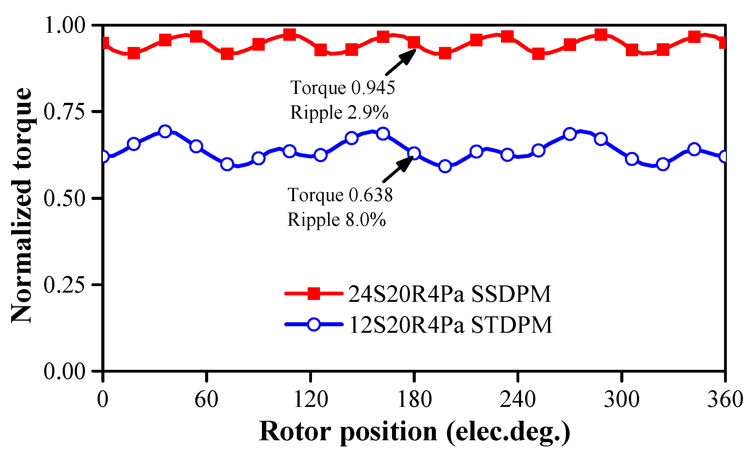
Comparison of torque waveforms of two dual-PM machines under the same copper loss (120 °C).
Figure 18.
Comparison of torque waveforms of two dual-PM machines under the same copper loss (120 °C).
Figure 19.
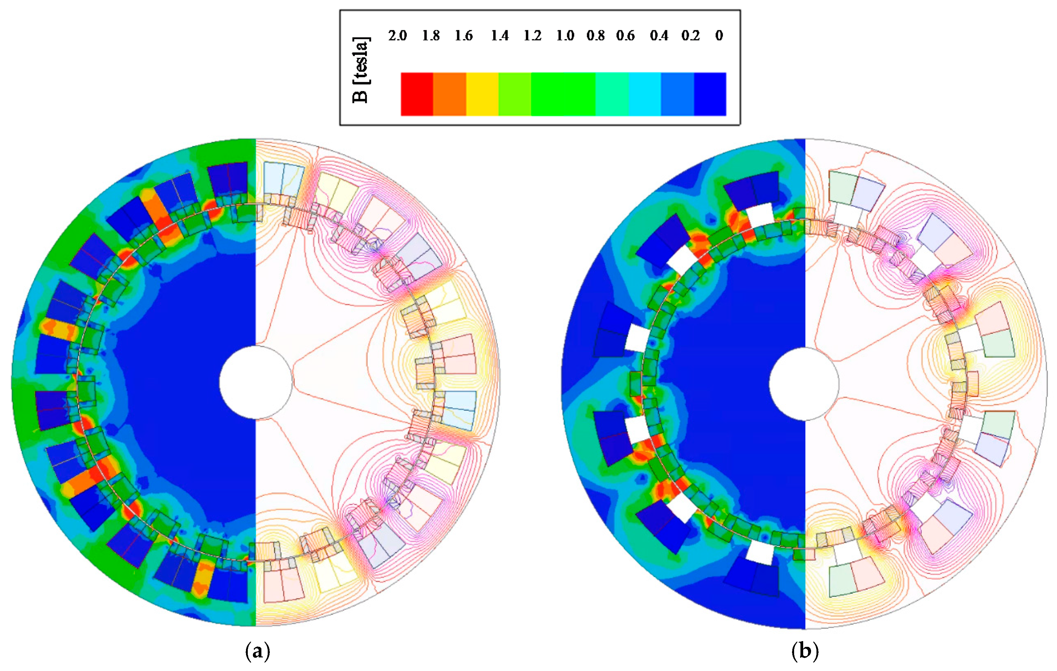
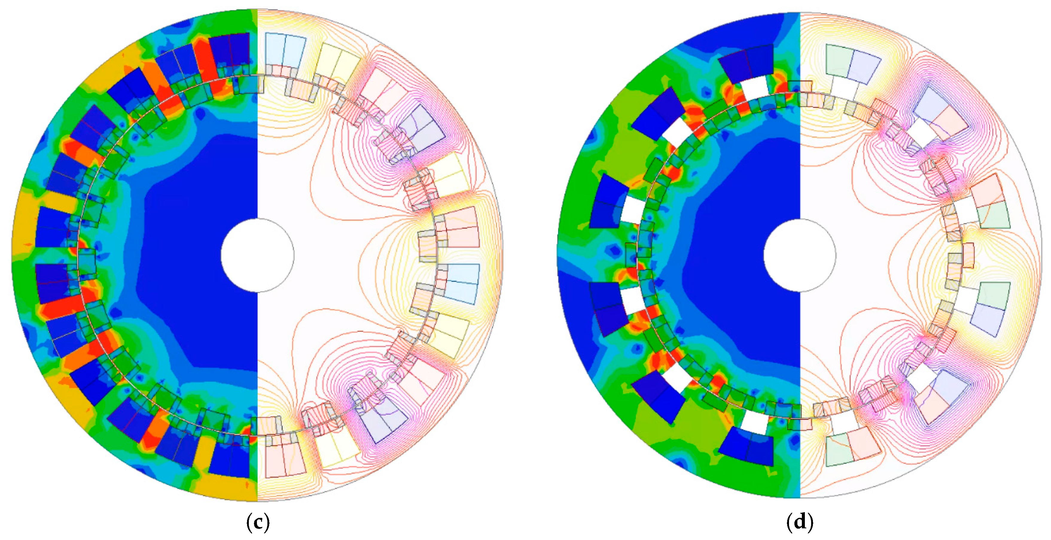
Flux density distributions of two dual-PM machines. (a) 24S20R4Pa SSDPM machine at open circuit condition; (b) 12S20R4Pa STDPM machine at open circuit condition; (c) 24S20R4Pa SSDPM machine at load condition (Id = 0 and Iq = Imax); (d) 12S20R4Pa STDPM machine at load condition (Id = 0 and Iq = Imax).
Figure 19.
Flux density distributions of two dual-PM machines. (a) 24S20R4Pa SSDPM machine at open circuit condition; (b) 12S20R4Pa STDPM machine at open circuit condition; (c) 24S20R4Pa SSDPM machine at load condition (Id = 0 and Iq = Imax); (d) 12S20R4Pa STDPM machine at load condition (Id = 0 and Iq = Imax).
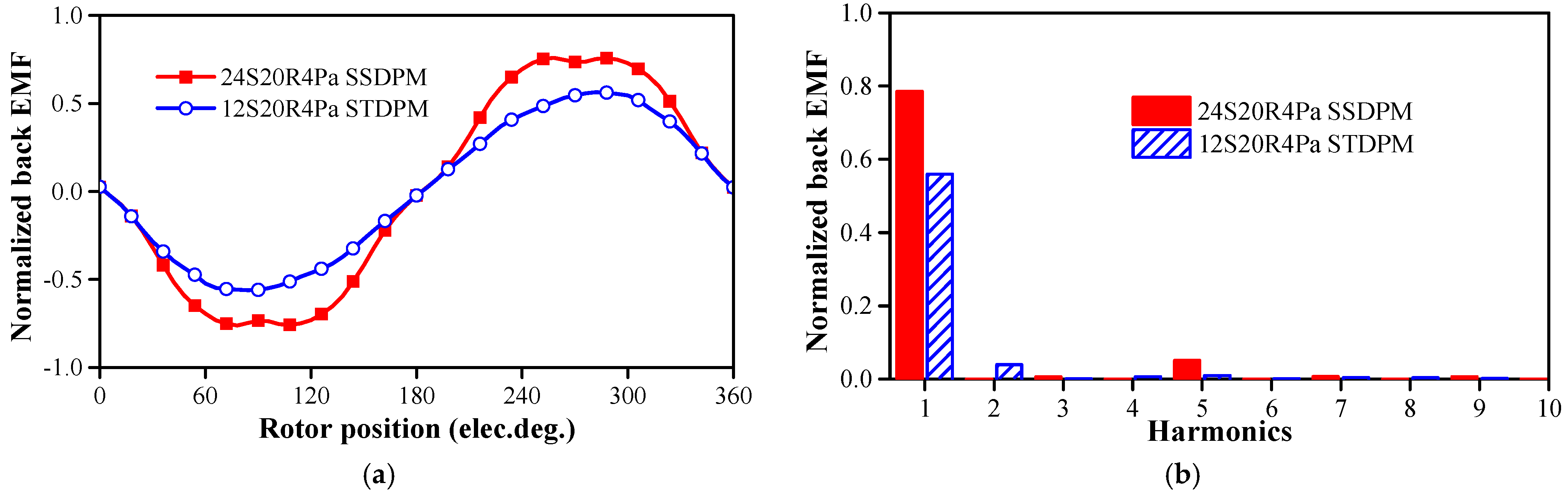
Figure 20.
Back EMFs of two dual-PM machines at 600 rpm. (a) Waveforms; (b) spectra.
Figure 20.
Back EMFs of two dual-PM machines at 600 rpm. (a) Waveforms; (b) spectra.
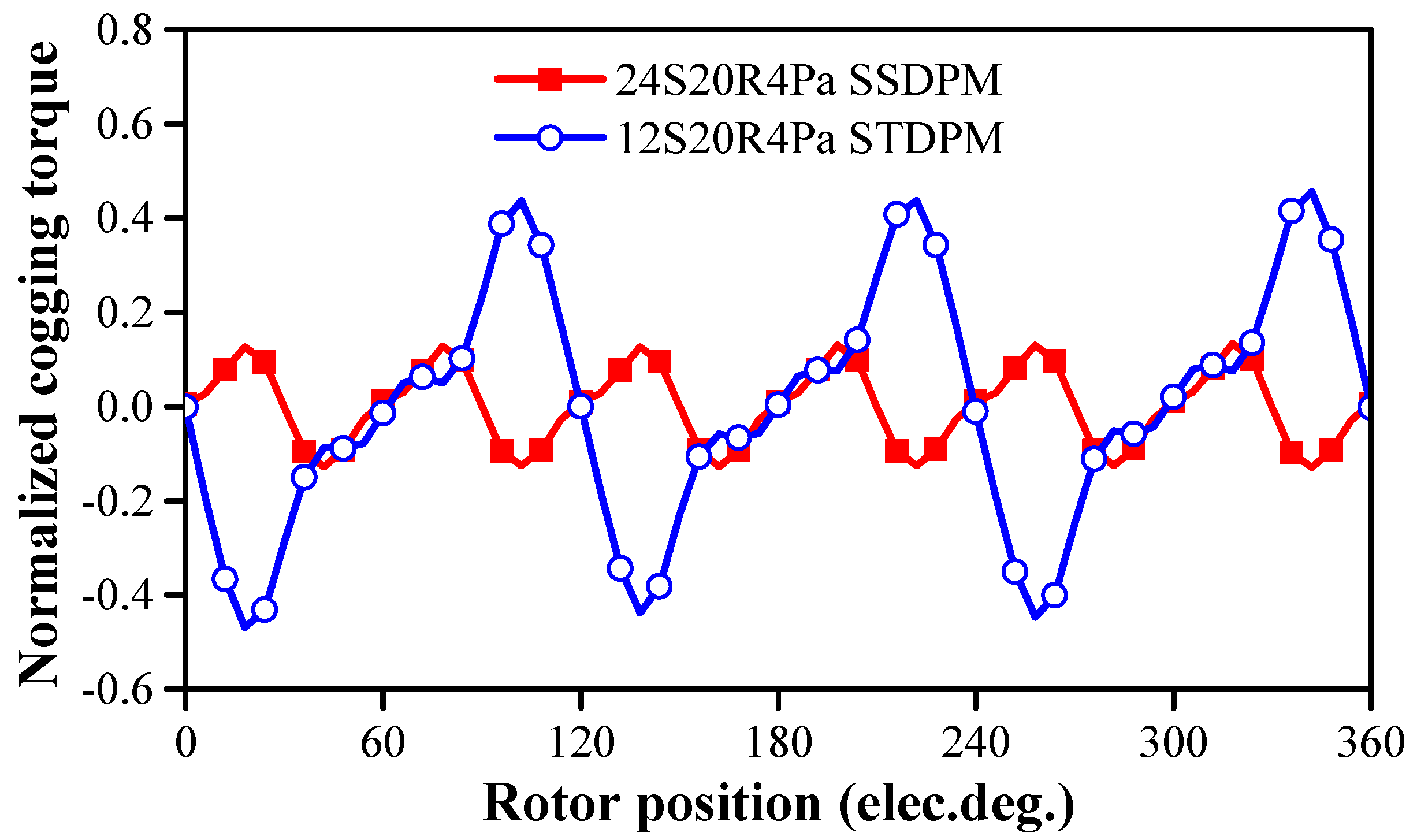
Figure 21.
Cogging torques of two dual-PM machines.
Figure 21.
Cogging torques of two dual-PM machines.
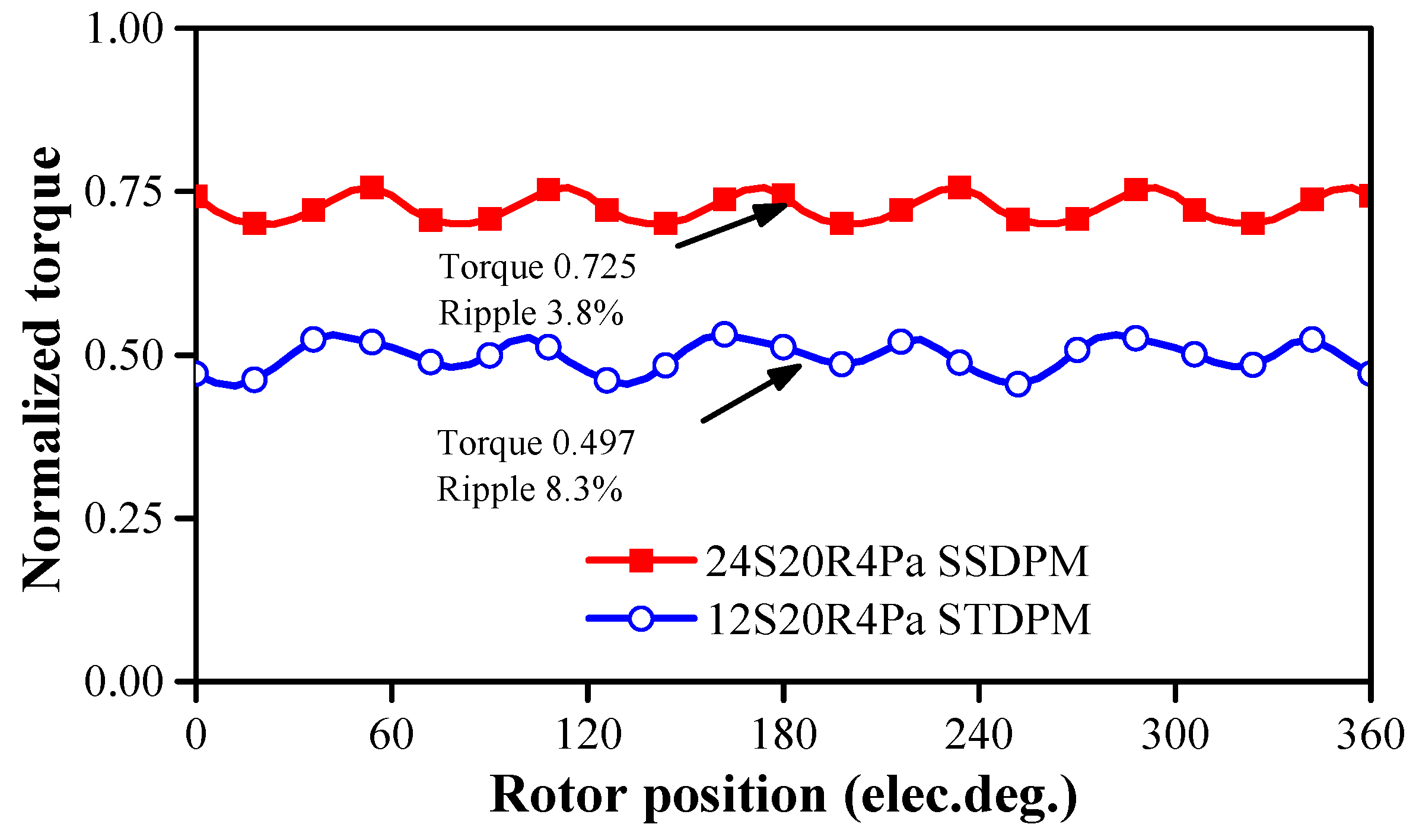
Figure 22.
Torque waveforms of two dual-PM machines when I = Imax and turn number per phase is adjusted to satisfy inverter requirements.
Figure 22.
Torque waveforms of two dual-PM machines when I = Imax and turn number per phase is adjusted to satisfy inverter requirements.
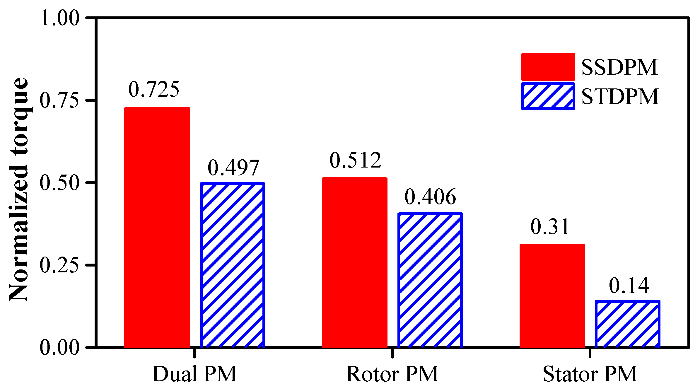
Figure 23.
Torque decomposition of two dual-PM machines using frozen permeability method.
Figure 23.
Torque decomposition of two dual-PM machines using frozen permeability method.
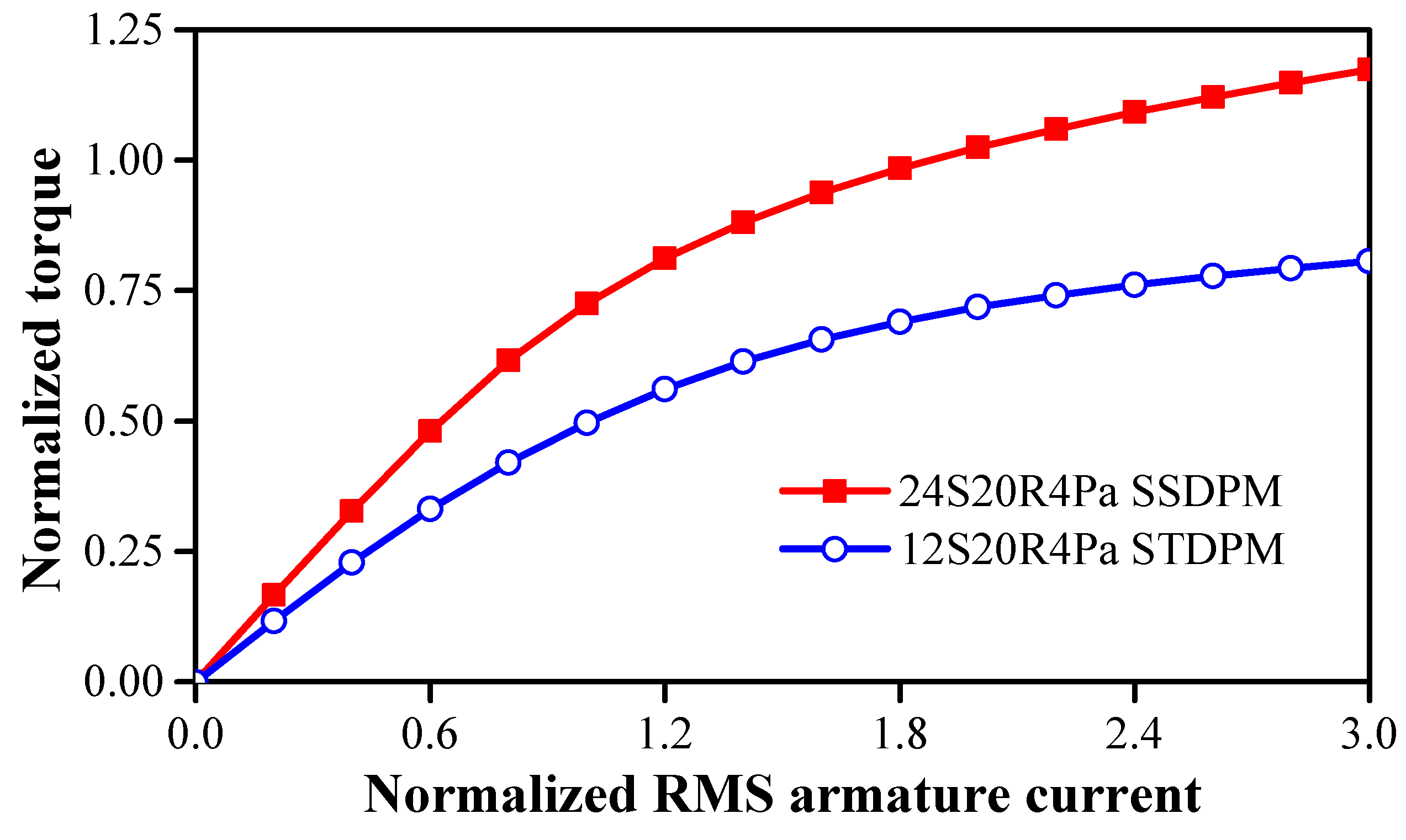
Figure 24.
Torques versus current of two dual-PM machines.
Figure 24.
Torques versus current of two dual-PM machines.
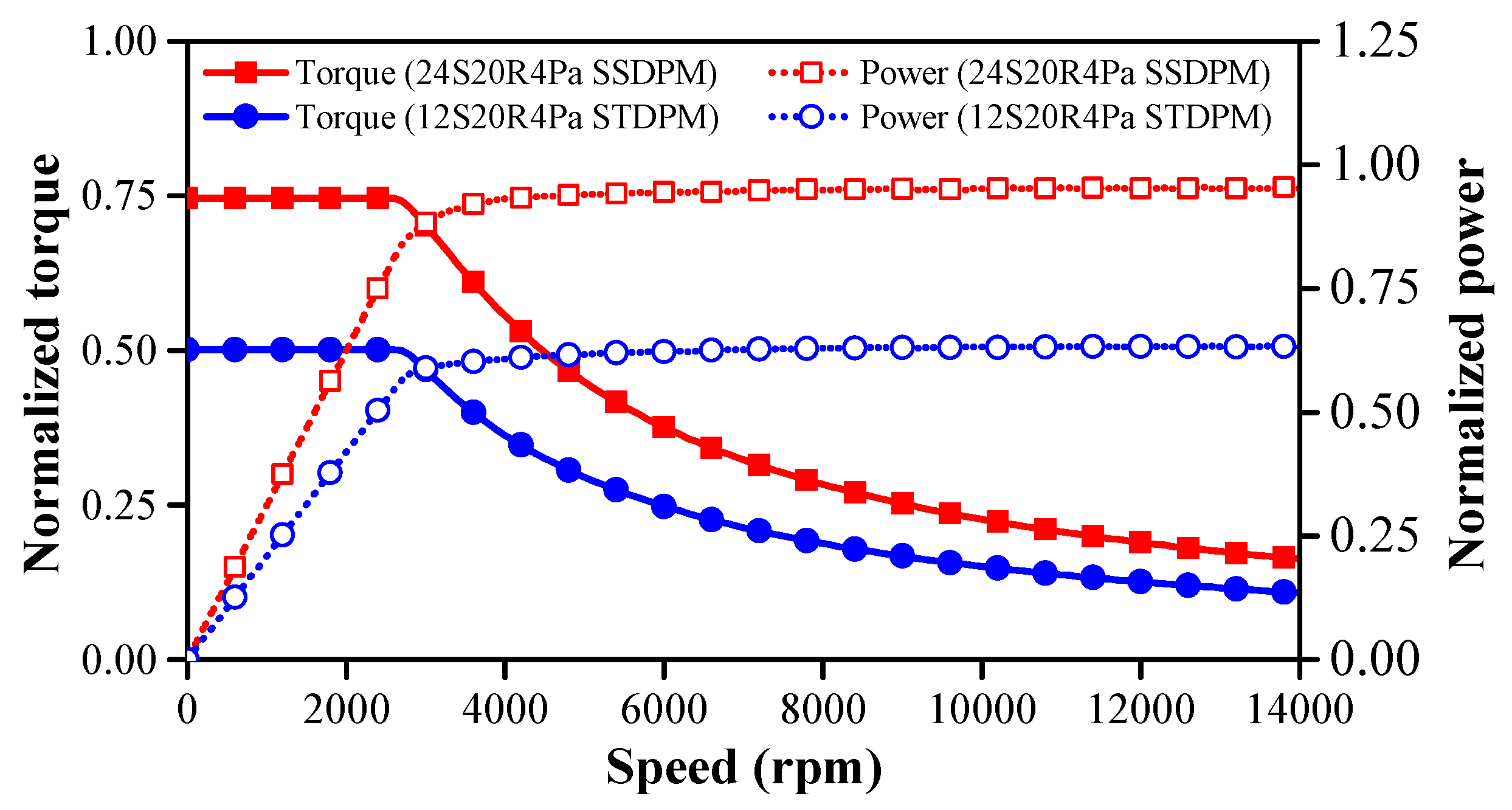
Figure 25.
Torques/powers versus speed of two dual-PM machines.
Figure 25.
Torques/powers versus speed of two dual-PM machines.
Table 1.
Parameters of optimized SSDPM machines with different slot/pole number combinations.
Table 1.
Parameters of optimized SSDPM machines with different slot/pole number combinations.
| Symbol | 12S11R | 12S13R | 12S10R | 12S8R | 12S7R | 18S17R | 18S16R | 18S15R | 18S14R | 18S13R | 24S23R | 24S22R | 24S20R | 24S19R | 24S16R | 24S14R |
| 1Pa | 1Pa | 2Pa | 4Pa | 5Pa | 1Pa | 2Pa | 3Pa | 4Pa | 5Pa | 1Pa | 2Pa | 4Pa | 5Pa | 8Pa | 10Pa |
| r3 (mm) | 100 |
| lstk (mm) | 140 |
| g (mm) | 0.5 |
| Br, µr | 1.3 T, 1.05 |
| tw (mm) | 11.7 | 8.5 | 13.5 | 16 | 18.2 | 5.75 | 9.2 | 10.3 | 10.3 | 10.6 | 5.0 | 6.5 | 6.95 | 8.4 | 8.6 | 9.6 |
| w2 (deg) | 10.4 | 17.6 | 26.2 | 30.3 | 35.9 | 13.1 | 15.4 | 16.2 | 18.0 | 18.3 | 9.9 | 9.9 | 10.5 | 10.9 | 12.5 | 17.5 |
| yk (mm) | 25.1 | 22.3 | 14.5 | 9.3 | 9.4 | 25.8 | 13.2 | 9.9 | 6.3 | 6.7 | 24.6 | 15.4 | 9.6 | 8.1 | 5.5 | 5.9 |
| r1 (mm) | 60.9 | 64.3 | 67.8 | 70 | 65.7 | 62.1 | 69.8 | 73.8 | 69.0 | 72.6 | 64.8 | 71.5 | 73.0 | 74.2 | 75.9 | 68.1 |
| h1 (mm) | 5.3 | 5.2 | 4.7 | 4.2 | 4.9 | 5.3 | 4.3 | 5.3 | 4.7 | 4.4 | 5.1 | 4.9 | 4.1 | 4.5 | 5.1 | 4.2 |
| h2 (mm) | 7.4 | 7.3 | 7.1 | 6.7 | 7.3 | 7.2 | 7.0 | 6.8 | 7.4 | 7.3 | 7.3 | 7.1 | 7.1 | 6.2 | 7.2 | 7.4 |
| Sslot (mm2) | 208.0 | 232.3 | 349.9 | 436.8 | 470.6 | 120.0 | 231.4 | 202.8 | 370.6 | 303.5 | 70.4 | 112.7 | 192.5 | 177.8 | 187.7 | 260.9 |
| w1hal | 0.63 | 0.58 | 0.60 | 0.66 | 0.4 | 0.41 | 0.5 | 0.64 | 0.58 | 0.52 | 0.39 | 0.41 | 0.58 | 0.53 | 0.4 | 0.51 |
| w2hal | 0.64 | 0.62 | 0.75 | 0.72 | 0.78 | 0.59 | 0.71 | 0.65 | 0.66 | 0.64 | 0.60 | 0.58 | 0.64 | 0.7 | 0.74 | 0.69 |
| Symbol | 30S29R | 30S28R | 30S26R | 30S25R | 30S23R | 30S22R | 30S20R | 36S35R | 36S34R | 36S33R | 36S32R | 36S31R | 36S30R | 36S29R | 36S28R | 36S26R |
| 1Pa | 2Pa | 4Pa | 5Pa | 7Pa | 8Pa | 10Pa | 1Pa | 2Pa | 3Pa | 4Pa | 5Pa | 6Pa | 7Pa | 8Pa | 10Pa |
| tw (mm) | 5.2 | 5.2 | 7.3 | 6.9 | 7.3 | 7.9 | 8.1 | 4.0 | 4.0 | 5.0 | 5.1 | 6.7 | 5.2 | 6.8 | 6.2 | 7.3 |
| w2 (deg) | 8.6 | 8.9 | 9.5 | 10.8 | 10.7 | 11.4 | 12.6 | 7.5 | 7.3 | 7.7 | 7.7 | 7.7 | 7.6 | 7.7 | 9.0 | 9.1 |
| yk (mm) | 24.8 | 14.6 | 8.6 | 7.7 | 6.3 | 5.1 | 4.3 | 23.5 | 15.0 | 9.9 | 9.7 | 7.3 | 6.2 | 6.8 | 5.5 | 4.8 |
| r1 (mm) | 64.9 | 74.2 | 76.3 | 77.9 | 73.9 | 74.2 | 71.4 | 67.5 | 67.5 | 77.8 | 75.3 | 78.1 | 76.9 | 78.7 | 77.4 | 78.5 |
| h1 (mm) | 5.4 | 4.0 | 4.9 | 3.8 | 3.8 | 3.8 | 3.7 | 3.8 | 4.4 | 5.5 | 4.7 | 3.5 | 3.5 | 3.5 | 4.5 | 3.9 |
| h2 (mm) | 6.9 | 6.9 | 6.4 | 7.4 | 7.0 | 6.5 | 7.1 | 6.4 | 6.6 | 7.1 | 6.5 | 7.4 | 6.0 | 7.4 | 6.7 | 7.1 |
| Sslot (mm2) | 44.4 | 80.3 | 105.0 | 114.9 | 165.9 | 168.2 | 197.8 | 42.0 | 122.7 | 64.1 | 96.1 | 90.7 | 129.6 | 89.8 | 111.8 | 101.4 |
| w1hal | 0.50 | 0.42 | 0.56 | 0.43 | 0.41 | 0.39 | 0.79 | 0.31 | 0.34 | 0.49 | 0.33 | 0.54 | 0.41 | 0.58 | 0.44 | 0.63 |
| w2hal | 0.38 | 0.57 | 0.50 | 0.66 | 0.55 | 0.68 | 0.54 | 0.41 | 0.48 | 0.39 | 0.40 | 0.55 | 0.53 | 0.50 | 0.45 | 0.49 |
Table 2.
Parameters of optimized 6-slot STDPM machines with a different split-tooth number and armature pole pair number.
Table 2.
Parameters of optimized 6-slot STDPM machines with a different split-tooth number and armature pole pair number.
| Symbol | 2 Split-Tooth | 3 Split-Tooth | 4 Split-Tooth |
|---|
| 6S11R1Pa | 6S10R2Pa | 6S8R4Pa | 6S17R1Pa | 6S16R2Pa | 6S14R4Pa | 6S23R1Pa | 6S22R2Pa | 6S20R4Pa |
|---|
| tw (mm) | 34.5 | 34.9 | 34.1 | 17.7 | 37.8 | 15.5 | 26.9 | 34.0 | 28.8 |
| w1 (deg) | 19.7 | 19.1 | 17.3 | 12.3 | 12.0 | 11.4 | 9.2 | 7.8 | 8.9 |
| yk (mm) | 22.4 | 21.0 | 13.8 | 25.4 | 16.1 | 9.5 | 25.8 | 14.9 | 11.2 |
| ht (mm) | 7.9 | 7.0 | 7.3 | 7.2 | 7.1 | 6.1 | 6.2 | 8 | 5.7 |
| so (deg) | 19.7 | 19.1 | 17.3 | 12.3 | 12 | 11.4 | 9.2 | 7.8 | 8.9 |
| r1 (mm) | 61.5 | 56.7 | 61.8 | 59.9 | 62.6 | 75.3 | 60.4 | 64.8 | 73.8 |
| h1 (mm) | 4.2 | 4.0 | 4.8 | 4.4 | 4.5 | 4.7 | 4.4 | 4.8 | 4.8 |
| h2 (mm) | 7.7 | 8.0 | 7.1 | 7.5 | 7.1 | 7.9 | 6.6 | 7.8 | 7.9 |
| Sslot (mm2) | 330 | 586.9 | 585.1 | 401.2 | 578.7 | 637.4 | 333.5 | 575.9 | 521.8 |
| w2 (deg) | 22.3 | 26.3 | 33.3 | 16.3 | 16.3 | 19.0 | 12.9 | 11.8 | 13.0 |
| w2hal | 0.85 | 0.80 | 0.87 | 0.57 | 0.53 | 0.56 | 0.45 | 0.59 | 0.58 |
Table 3.
Parameters of optimized 12-slot STDPM machines with a different split-tooth number and armature pole pair number.
Table 3.
Parameters of optimized 12-slot STDPM machines with a different split-tooth number and armature pole pair number.
| Symbol | 2 Split-Tooth | 3 Split-Tooth | 4 Split-Tooth |
|---|
| 12S23R1Pa | 12S25R1Pa | 12S22R2Pa | 12S20R4Pa | 12S19R5Pa | 12S35R1Pa | 12S34R2Pa | 12S32R4Pa | 12S31R5Pa | 12S47R1Pa | 12S46R2Pa | 12S44R4Pa | 12S43R5Pa |
|---|
| tw (mm) | 14.6 | 19.9 | 18.6 | 22.2 | 23.0 | 6.7 | 21.7 | 22.1 | 22.4 | 11.7 | 16.1 | 21.8 | 15.8 |
| w1 (deg) | 8.6 | 10.4 | 8.9 | 8.3 | 9.4 | 6.4 | 6.6 | 6.2 | 6.0 | 4.6 | 4.1 | 4.2 | 3.8 |
| yk (mm) | 24.3 | 22.6 | 16.1 | 12.4 | 12.0 | 24.7 | 17.4 | 10.2 | 11.1 | 24.4 | 18.9 | 12.2 | 8.6 |
| ht (mm) | 7.6 | 6.5 | 7.5 | 8.1 | 6.8 | 6.5 | 7.6 | 6.9 | 5.9 | 6.1 | 5.8 | 6.6 | 5.4 |
| so (deg) | 8.6 | 10.4 | 8.9 | 8.3 | 9.4 | 6.4 | 6.6 | 6.2 | 6.0 | 4.6 | 4.1 | 4.2 | 3.8 |
| r1 (mm) | 59.3 | 61.2 | 64.8 | 66.9 | 69.1 | 61.4 | 65.5 | 71.7 | 68.7 | 61.0 | 64.5 | 73.1 | 73.4 |
| h1 (mm) | 3.8 | 4.9 | 4.6 | 4.5 | 4.1 | 4.6 | 4.2 | 3.0 | 3.0 | 4.9 | 2.60 | 3.6 | 3.2 |
| h2 (mm) | 7.7 | 6.3 | 7.6 | 5.6 | 7.6 | 5.8 | 7.0 | 6.7 | 8.0 | 3.7 | 5.9 | 6.9 | 7.6 |
| Sslot (mm2) | 190 | 168.2 | 248.2 | 246.2 | 231.3 | 210.9 | 173 | 235.6 | 281.8 | 205.8 | 242.3 | 167.8 | 351.4 |
| w2 (deg) | 12.6 | 9.9 | 12.9 | 13.4 | 12.6 | 7.5 | 6.9 | 7.6 | 7.8 | 6.1 | 5.5 | 5.8 | 6.3 |
| w2hal | 0.47 | 0.58 | 0.52 | 0.47 | 0.54 | 0.41 | 0.57 | 0.69 | 0.58 | 0.49 | 0.49 | 0.47 | 0.42 |
Table 4.
Comparison of electromagnetic performances with a different rotor slot number selection under 600 rpm and the same copper loss.
Table 4.
Comparison of electromagnetic performances with a different rotor slot number selection under 600 rpm and the same copper loss.
| | Normalized Torque (p.u.) | Normalized Power Factor (p.u.) | Normalized Iron Loss (p.u.) | Efficiency |
|---|
| 12S11R1Pa | 0.625 | 0.547 | 0.36 | 83.0% |
| SSDPM |
| 12S13R1Pa | 0.597 | 0.493 | 0.38 | 82.3% |
| SSDPM |
| 12S23R1Pa | 0.550 | 0.293 | 0.89 | 80.3% |
| STDPM |
| 12S25R1Pa | 0.477 | 0.267 | 0.95 | 77.8% |
| STDPM |
Table 5.
Comparison of electromagnetic performances of two dual-PM machines under 600 rpm and the same copper loss.
Table 5.
Comparison of electromagnetic performances of two dual-PM machines under 600 rpm and the same copper loss.
| | 24S20R4Pa SSDPM | 12S20R4Pa STDPM |
|---|
| Normalized torque (p.u.) | 0.725 | 0.497 |
| Torque per PM volume (p.u./cm3) | 1.34 | 1.28 |
| Normalized power factor (p.u.) | 0.93 | 0.69 |
| D-axis inductance (µH) | 56.9 | 61.1 |
| Q-axis inductance (µH) | 62.59 | 61.4 |
| Normalized iron loss (p.u.) | 0.33 | 0.24 |
| Efficiency | 93.5% | 89.7% |


