
A Cyber-Physical All-Hazard Risk Management Approach: The Case of the Wastewater Treatment Plant of Copenhagen


1
SINTEF Community, S.P. Andersens vei 3, 7031 Trondheim, Norway
2
BIOFOS, Refshalevej 250, 1432 Copenhagen, Denmark
3
SINTEF Digital, Strindvegen 4, 7034 Trondheim, Norway
*
Author to whom correspondence should be addressed.
Water 2023, 15(22), 3964; https://doi.org/10.3390/w15223964
Submission received: 25 September 2023
/
Revised: 31 October 2023
/
Accepted: 13 November 2023
/
Published: 15 November 2023
(This article belongs to the Special Issue Cyber-Physical Security for the Water Sector)
Abstract
:The ongoing digitalization of critical infrastructures enables more efficient processes, but also comes with new challenges related to potential cyber-physical attacks or incidents. To manage their associated risk, a precise and systematic framework should be adopted. This paper describes a general methodology that is consistent with the Risk Management ISO (31000-2018) and builds on specific tools developed within the H2020 digital-water.city (DWC) project. The approach has been demonstrated for a digital solution of the DWC project that allows to visualize inflow predictions for the Wastewater Treatment Plant (WWTP) in the city of Copenhagen. Specifically, the risk assessment and risk treatment steps are demonstrated in the case of the spoofing of the web interface where misleading forecast data may turn into fallacious maintenance schedules for the operators. The adopted methodology applied to the selected use case led to the identification of convenient measures for risk mitigation.
1. Introduction
Fundamental activities in an organized society often rely on critical infrastructures, which are defined as those infrastructures whose damage, destruction, or disruption by natural disasters or malicious behaviour may have a significant negative impact on the security and the well-being of the society itself. The Directive (EU) 2022/2557 of the European Parliament and of the Council of 14 December 2022 on the resilience of critical entities (CER Directive) aims at strengthening the resilience of critical infrastructure to a range of threats, including natural hazards, terrorist attacks, insider threats, or sabotage. The new directive, that replaced the European Critical Infrastructure Directive of 2008, covers 11 sectors and, among others, adds water and wastewater, which were missing in the previous one. To implement the CER Directive, Member States will need to adopt a national strategy and carry out regular risk assessments to identify entities that are considered critical or vital for the society and the economy.
Threats to the service caused by one sector could result from failures in other interconnected sectors, and as stated by the Directive, Member States “should consider the extent to which sectors depend on one another”.
Along with the process of digitalization of the water and wastewater sectors, new vulnerabilities are produced by the increasing risk of service disruption due to cyber-attacks. Indeed, critical infrastructures are nowadays made of two interconnected parts, the physical and the cyber layers, where physical infrastructures are supported by sensors, actuators, telecommunication systems, and software to operate more effectively [1,2]. A deep understanding of the connections between these layers of critical infrastructures allow to enhance the preparedness to cyber-physical attacks or incidents. As a part of the planning and implementation of digital solutions to support critical processes, risk management plays a fundamental role in limiting the associated risk in terms of economic, social, and environmental losses [3]. In fact, risk management offers a systematic way to help address the vulnerabilities brought by the adoption of digital solutions. The systematic steps are described by the risk management process in ISO standard 31000-2018 [4], illustrated in Figure 1.
Together with physical threats, cyber-attacks are more and more frequently observed in water organizations and critical infrastructures (CIs) in general, due to the high increase in digital applications to improve the efficiency of processes and physical devices. As described in [5,6], different kinds of threats have been detected in the recent years connected with digital solutions, also targeting the water sector. The presented approach extends and customizes the work of the STOP-IT project (https://stop-it-project.eu, accessed on 17 August 2023) to the DWC project (https://www.digital-water.city, accessed on 17 August 2023), which deals with 15 innovative digital solutions (DSs) in five European cities. These DSs have been developed in the context of water organizations. The connected potential risk events and associated potential risk reduction measures were identified by the project partners, within the Risk Identification Database (RIDB) and Risk Reduction Measure Database (RRMD), where potential risk events and mitigation measures are described with a consistent semantic structure [7,8,9]. Additionally, within the DWC project, Bour et al. [5] classified the attacks against digital solutions into six categories:
- -
- Attacks against infrastructure (e.g., Denial of Service (DoS) attack).
- -
- Attacks on IoT sensors (e.g., sensors being impersonated to send misleading values to the backend server, or credentials of sensors being used to gain access to a private network, thus extending the attack surface).
- -
- Attacks on ML/AI (e.g., specially crafted input to mislead the underlaying algorithm). These attacks can be chained after the attacks on IoT sensors to control the input.
- -
- Attacks on applications (e.g., web, mobile, etc.).
- -
- Human errors/failures (e.g., a user is given more access to an application than required, exposing sensitive data).
- -
- Social engineering (e.g., attackers may trick operators into performing harmful actions).
A cyber-physical all-hazard risk management approach has been designed with the purpose of being applied by an organization that manages a CI and wishes to improve its cyber-physical protection. It helps identify, analyse, and prioritize the full range of potential cyber-physical hazards. The approach takes into account different methods developed for performing a risk management process for risk identification, analysis, evaluation, and treatment that can be used by a team of experts within the organization to properly go through the steps of risk management. The team should have a clear overview of each responsibility about the involved assets, distinguishing a sub-group who is in charge of the overall organization’s strategies and another sub-group who is capable of providing knowledge about the system’s processes and IT solutions. By following the steps presented in the discussed approach, supported by the exemplification through a use case, the users can perform similar assessments, adapted to the specific context, by following the proposed procedure. The use case consists of a wastewater treatment plant (WWTP) with given characteristics during periodic maintenance and under a cyber-attack. The presented approach has been developed as a joint collaboration between the Partners SINTEF, BIOFOS, and DHI. One of the digital solutions (DS) developed within the DWC project (namely, “Web platform for integrated sewer and wastewater treatment plant control”, as reported in [7]), developed by BIOFOS and DHI, was selected as the target of a cyber-attack scenario, considering a specific threat, i.e., the spoofing of the web interface where forecast data are visualized by operators, leading to a wrong flow prediction and thus to a wrong maintenance schedule.
The approach discussed throughout the paper relies on a structured methodology to support organizations managing CIs to deal with cyber-physical protection. It might inspire the definition of a comprehensive framework for cyber and non-cyber resilience of critical entities as required by the CER Directive. After having properly defined the context and identified the risk, the proposed approach to support the risk analysis combines two methods to estimate consequences and probabilities, i.e., a stress-testing procedure and an interview-based assessment, respectively. The two methods were originally applied uncoupled from each other in the context of water supply systems within the STOP-IT project. In this paper, the risk analysis approach has been generalized, extending its domain of application. The resulting risk is finally evaluated, and appropriate risk treatment measures are considered. The novel contribution of this paper resides in the original combination and adoption of different methods for risk identification, analysis, evaluation, and treatment, which are hereby applied for a case study, fitting the general methodology provided by ISO 31000-2018 [4].
Throughout the document, firstly, the methodology is presented, including the description of each risk management step according to the adopted ISO framework, as well as the selected methods and the technical details of the case study. Secondly, the results on the case study with the adopted methods for each step are presented and discussed. Finally, the conclusions are provided, including limitations and potential improvements of the proposed approach, followed by the future perspectives of the study.
2. Materials and Methods
Referring to Figure 1, guidance on the following steps is provided:
- Defining the context.
- Risk identification.
- Risk analysis.
- Risk evaluation.
- Risk treatment.
Monitoring and review, recording and reporting, and communication and consultation are activities to be carried out and promoted continuously by risk managers across the different steps.
2.1. Defining the Context
2.1.1. Defining the Scope and Criteria within ISO Framework
The aims of defining the context are to set the basis for performing the risk management process, describing the system of interest with external and internal conditions that can influence the risk management steps, defining responsibilities, and setting the risk criteria against which the risk will be assessed. The risk management process should be aligned with the utility objectives and strategies and should target the specific risk affecting the achievement of those objectives. Thus, defining the context is a necessary step for risk management, which concerns the identification of all external and internal variables to be considered when managing risk. The primary step for the context description phase is to define the scope for which risk is assessed. The work hereby presented deals with risks related to cyber-physical threats in the water sector. Moreover, the list of the consequence dimensions to be assessed, the relative scales to define probability frequencies and consequence severity, and the corresponding risk level scales have to be set in advance. Finally, risk criteria must be defined and agreed in order to judge the magnitude of computed risk events. A risk criterion can be defined as the critical value of a Key Performance Indicator (KPI) that should not be exceeded, and if exceeded, risk reduction measures should be adopted.
KPI ≤ target value → risk mitigation measures are not needed.
KPI > target value → risk mitigation measures are needed.
The risk criteria might also cover more shaded areas of risk severity characterization, with less clear-cut categories not limited to “high” and “low” risk levels, covering also intermediate zones of “medium” risk. The definition of the ranges of combinations of probabilities and consequences reflecting different levels of risk severity are often represented in the form of risk matrices when different categories of probability and consequence dimensions are combined.
As an example, a scale of probability (p) could be given by the following levels:
- -
- Very unlikely (VU): less than once per 100 year (p < 0.01).
- -
- Remote (R): once per 10–100 year (0.01 ≤ p < 0.1).
- -
- Occasional (O): once per 1–10 year (0.1 ≤ p < 1).
- -
- Probable (P): once to 12 times a year (1 ≤ p < 12).
- -
- Frequent (F): more than once a month (p > 12).
In terms of consequences, a scale should be also defined with respect to the selected KPI, as in the example provided in the following list:
- -
- Very low (VL): KPI < 1.
- -
- Low (L): 1 ≤ KPI < 3.
- -
- Medium (M): 3 ≤ KPI < 10.
- -
- High (H): 10 ≤ KPI < 30.
- -
- Very high (VH): KPI ≥ 30.
By combining the categories of probability (p) and consequence (c), a risk matrix may be derived, as shown in Table 1. The organization can assign different levels of risk, color-coded in Table 1, for different combinations of p and c [10].
For instance, the given risk event may fall into the grey, green, and yellow areas with low, acceptable, or tolerable risk or into the orange and red areas with high or very high level of risk; thus, mitigation measures should be implemented accordingly.
2.1.2. The Context of the Considered Case Study
The Damhusåen WWTP in the Greater Copenhagen area, managed by BIOFOS, was selected as the case study. One of the BIOFOS’s main objective is the reduction in the pollution of the environment produced by treatment activities. Risk management is applied to deal with cyber-physical attacks or incidents that may damage the environment when the infrastructure of provided services are not sufficiently protected. The combined sewer system connected to the WWTP covers an area of 55 km2, delivering both rain- and wastewater from a population of 305,000 inhabitants, while the plant loading is 378,000 population equivalent (PE) when the loading of industry is included. The design capacity is 350,000 PE; hence, currently, the treatment plant loading is more than 100% loaded. Normal dry weather inflow for WWTP can reach 5000 m3/h, but inflow under heavy rain events can reach up to 28,000 m3/h, due to the combined sewer system. Under heavy rain events, the daily inflow can reach 500,000 m3/d. Inflow with diluted wastewater during rain events with inflow of over 10,000 m3/h is only treated using mechanical treatment. Under normal conditions, the wastewater is treated both mechanically and biologically before it is discharged to the receiving water at Øresund, 1.5 km out in the sea. The WWTP is characterized by four lines where all the biological treatment steps are run in parallel. The capacity of each line is equal to 2500 m3/h, for a total treatment capacity of 10,000 m3/h, as mentioned above. To cover the high peaks of inflow due to the rain events, the WWTP is equipped with equalization tanks with a total volume of 44,000 m3. In case of maintenance of one of the four treatment line, BIOFOS estimated a time of up to 24 h to restore normal operation conditions if the line is required to be functional again.
Firstly, the mechanical treatment, consisting of screening, grit and grease removal, and primary settling, is performed to reduce the content of unwanted substances that could interfere with biological treatment, as well as to remove a significant part of the suspended solids in wastewater.
In the mechanical screens, all larger particles over about 8 mm are removed. The screening material is dewatered and transported for external incineration at a waste incineration plant. In the grit and grease removal, larger sand and stone particles are separated from the incoming wastewater. Air is pumped into the tank to promote the separation of sand and grease. The extracted sand is washed and sent to external reuse, e.g., for road construction work. The removed grease is pumped over to the treatment plant’s digester tanks, where it is converted into biogas. The primary tanks act as large sedimentation tanks, where the waste suspended solid content settles, and around 50–60% of the suspended material found in the incoming wastewater is removed. Because of its high energy content, primary sludge is pumped over to the digester, where it is converted into biogas.
Secondly, the primary treated wastewater undergoes an advanced biological treatment, where the wastewater’s content of organic matter, nitrogen, and phosphorus is reduced. However, to achieve a stable phosphorus removal under all conditions, a smaller amount of precipitation with chemicals is needed. Moreover, to reach the necessary treatment capacity, all four treatment lines must be in operation for the plant to have full biological and hydraulic treatment capacity. The biological purification includes the involvement of hydrolysis tanks, aeration tanks, and secondary tanks.
In the first type of tanks mentioned for biological purification, the incoming wastewater is mixed with activated sludge (return sludge), consisting of bacteria which reduce the content of organic matter, nitrogen, and phosphorus through biological processes. In these tanks, the hydrolysis of active sludge takes place, forming easily degradable organic matter, which promotes biological phosphorus and nitrogen removal. In the aeration tanks, the wastewater is treated biologically within two tanks that alternate oxygen-rich and oxygen-poor conditions. In the oxygen-rich phase, a breakdown of organic matter and a biological conversion of the nitrogen content from ammonia to nitrate (nitrification) take place. In the low-oxygen phase, aeration is stopped; hence, anoxic conditions occur, and a biological conversion from nitrate to free nitrogen gas takes place with the use of organic matter (denitrification) because the bacteria need organic matter to perform the denitrification process. The nitrogen gas produced by the bacteria bubbles up to the atmosphere. Moreover, to obtain a low concentration of phosphorous in the effluent of the aeration tank, a small amount of precipitation chemicals is dosed to the outlet of the aeration tank. The precipitated phosphorus is then taken out in the secondary clarifier as a chemical sludge. In the secondary tanks, the activated sludge settles together with the part of the wastewater’s phosphorus content that has been chemically removed. The settled activated sludge is pumped back to the start of the biological treatment as a return sludge, and the treated wastewater is finally directed to the receiving waters. To keep the activated sludge concentration constant, a smaller part of the activated sludge is constantly taken out as biological surplus sludge/secondary sludge. Since the activated sludge still has a high energy content, it can also be fed to the digester, where a significant part of the biological sludge is converted into biogas.
Both the primary sludge and the secondary sludge are pumped into the digesters, where biogas is produced. The biogas produced consists of 62% methane and 38% carbon dioxide gas. In this process, the amount of sludge is reduced by 35% approximately, as the carbon in the sludge is converted into methane and carbon dioxide gas. The biogas is used to make electricity and heat at the treatment plant. Specifically, the produced electricity is sold to the grid, while the produced heat is used to heat up the digesters, and the surplus heat is sold to the city district heating grid. The remaining sludge from the digester is dewatered to 20–25% dry matter and to a water content of 75–80%. The sludge is transported to final incineration at one of BIOFOS incineration plants.
Information regarding plant loading per day and the quality of biologically treated wastewater, in terms of COD (Chemical Oxygen Demand) and representing the organic matter, nitrogen, and phosphorus, is reported in Table 2. Specifically, inlet concentrations and plant loading per day are shown together with the effluent concentrations and the effluent discharge per day. Based on the plant loading and the effluent discharge, the percentage of removal of organic matter and nutrients can be calculated.
Although the treatment plant is highly loaded, all effluent demands at the discharge permit are well below the thresholds, depicted in Table 2 as effluent required concentrations. The analysed treatment plant is highly automated and controlled by a SCADA system (supervisory control and data acquisition system) that visualizes plant operation, handles alarms, and provides access to graphs and reports. Beyond the SCADA system, an advanced online control system (expert system) optimizes and automates the operation of the water treatment line with online sensors (flow, oxygen, ammonium, nitrate nitrogen, orthophosphate, water level, temperature, suspended solids, and sludge blanket). The system has different modules that optimize the nitrogen removal, biological phosphorus removal, and chemical phosphorus precipitation. Outside normal working hours the plant is remotely controlled from the central control room, nevertheless at least one employee monitors the status of the plant during evening and night hours.
Overall, the WWTP is optimised to control pollutions through advanced digital solutions, therefore managing the risk connected with the digitalization of such infrastructure is crucial.
In light of the current scientific knowledge and the best engineering practice, the storm water and sanitary systems should be separate, particularly to allow a suitable wastewater treatment. However, for combined systems, the inflow is characterized by a significant degree of dilution during and just after the rain events, having the actual inflow value much higher than the expected value for wastewater flow of a given hour of the day. Under emergencies such as cyber-physical attacks or extreme stormwater events, the existing wastewater system based on combined sewers might entail the by-pass of biological treatments to directly discharge into a receiving water body, according to past design criteria of CSO (Combined Sewer Overflow) devices in Europe [11,12]. Specifically, a dilution coefficient r, given in (1) and with a value ranging from 3 to 6, is considered as the minimum critical value rc under which all the inflows should be properly treated [13].
where Qr is the inflow generated by the rain, and Qww is the contribution of wastewater flow.
Obviously, in the stage of the design of CSO devices, the adoption of lower values of the critical dilution coefficient rc leads to an increase in CSOs and a consequent decrease in biologically treated volumes. For the case study, the risk criteria have been defined considering that the critical dilution coefficient rc is equal to three.
When the system has a reduced capacity due to maintenance operations, the equalization tanks might not be enough to cover water overloads, since with a reduced capacity, the plant might not be able to treat all the wastewater characterized by dilution coefficients below the designed rc. Knowing in advance the expected inflow for the next 48 h, the web application developed within the DWC project would help in planning the maintenance of each of the WWTP lines, without consequences in terms of undiluted and untreated overflows of wastewater, despite the reduced treatment capacity.
Usually, the maintenance is performed during dry weather because, in that case, there is no necessity of using all the four parallel treatment lines of the WWTP. The critical conditions should be identified during the phase of risk analysis, but it is possible to hypothesize in advance that they are likely to occur if the attack is performed few hours before or during small–medium rain events. In this case, the operators might perform maintenance expecting dry weather conditions, but they will eventually experience a higher inflow than expected because of the considered attack; thus, this will potentially lead to untreated wastewater that will not sufficiently diluted, according to the designed rc.
2.2. Risk Identification
2.2.1. Risk Identification within ISO Framework
Since the objective of the presented risk management process is the cyber-physical protection of CIs, the risk identification step consists of the identification of risk events, due to physical, cyber, or physical-cyber threats, that will eventually have negative impacts on the achievement of service goals of organizations such as the utilization of CIs. Before analysing and evaluating the level of risk due to a certain cyber-physical attack in a water system, different aspects of that risk should be clarified. A proper risk description should comprise four elements, namely, sources, type of event, causes, and consequences [14]. Information useful to support risk identification includes expert knowledge and judgement, personal and organizational experiences, checklists, historical records, incident databases, previous risk registers, and reports from previous risk assessments. Identifying the events and their possible paths is an important and not straightforward step in the risk management process. Each risk event has its causes and understanding them can significantly help in estimating the level of risk. The risk causes, type of threat, and consequences are parts of each event path [15]. The mentioned RIDB identifies the type of threats, the sources of risk, the description of the events, and the type of consequences produced.
2.2.2. Adopted Approach for the Identification of the Considered Risk
The considered digital solution allows a water utility to visualize the predictions of the flow entering the WWTP 48 h in advance. Accurate rain forecasts are the inputs for a Machine Learning (ML) model that provides the timeseries of the mentioned flow, allowing optimized operations of the treatment process and improved schedules of maintenance. Specifically, the maintenance would be performed when dry time is expected. If a rain event is expected, the WWTP should work at full capacity because of the expected high loads to be treated. However, if the internal attacker modifies the visualized data to hide a rain event and the corresponding flow predictions, the water organization might start the programmed maintenance on one of the gate valves installed on the treatment lines. Therefore, if the internal attacker knows about the planned maintenance and manages to change the web interface visualization for the following 48 h into a typical condition of dry weather, some issues may arise because of the unexpected inflow. According to BIOFOS, the recovery of full capacity would be restored in 24 h.
The RIDB adopted for the case study covers the events identified by DWC partners as the most relevant risks related to their digital solutions developed in the project. The RIDB of the DWC project builds on the approach provided by the STOP-IT project that focused on cyber-physical attacks in water supply systems (available at https://risk-explorer.digital-water.city/event, accessed on 17 August 2023).
The events included in the RIDB should be considered as individual “building blocks” from which the complex risk scenarios can be derived by their combination. Therefore, the RIDB does not include events generated by the combination of multiple risks.
The sentence’s structure is the same for each record to ensure consistency, as shown in Figure 2.
The user of the database can create a new event in the RIDB if the risk event of interest is not included, maintaining the same structure in each record.
2.3. Risk Analysis
2.3.1. Risk Analysis within the ISO Framework
After having identified the risk events, the phase of risk analysis should be undertaken. During this step, the probabilities and consequences are examined to assess the frequency and the impact of the identified risks on the water system. The risk analysis will also determine which risk factors potentially have a greater impact on the analysed system [16]. In this step, understanding how to model the risk event is key, keeping in mind which data would be required in the analysis in relation to the risk criteria set a priori, and which variables are the most relevant for the identified risk event (e.g., potential critical areas, number of affected individuals, etc.). During the risk management process, the consequence assessed for the specific dimensions of impacts (e.g., economic, reduction in service, environmental, organizational resilience, etc.) could be quantified through KPIs [17] and combined with the estimation of the dimensionless probability of a successful cyber-attack. When possible, risk is assessed by multiplying consequence with the probability of success (Risk = Probability × Consequence).
As a possible risk criterion, the computed risk in terms of the selected KPI may be compared with a target value so that the risk manager can decide whether or not the risk level is acceptable or tolerable.
In the water infrastructure domain, a methodology that involves the stress-testing of drinking water supply systems have been developed in the STOP-IT project through the RAET (Risk Assessment and Evaluation Toolkit). The stress-testing platform (STP) [18] integrated into RAET can simulate both physical and cyber sub-systems, coupling the simulation environment of the physical layer to an emulation environment able to model the cyber layer of the water system control and communication infrastructure (e.g., from SCADA to PLCs to monitoring), where cyber protection solutions will be implemented, when cyber-attacks will be attempted. The platform allows to analyse, for example, the effects of introducing malware to the supervisory system and trace these effects to KPI.
For risk analysis, there are three types of methods used for determining the level of risk, namely, qualitative, semi-quantitative, and quantitative methods [19].
Qualitative Methods: This type of approach is often adopted for decision-making based mainly on expert judgment, experience, and intuition. These methods can be used when the level of risk is low and does not warrant the time and resources necessary for making an extensive analysis. These methods are also used when the numerical data available are not adequate for a more extensive computational and quantitative analysis; thus, it would serve as the basis for a subsequent, more detailed analysis. The qualitative methods include brainstorming, questionnaires and interviews, evaluation for multidisciplinary groups, judgment of specialists and experts, etc.
Semi-Quantitative Methods: In this type of approach, classifications and scores based on empirical formulas are usually adopted, with calculations targeted on retrieving the ranges of likelihood and consequence of a certain risk event. The classifications are shown in relation to an appropriate scale for calculating the level of risk. High attention should be provided with respect to the adopted scale, in order to avoid misunderstandings or misinterpretations of the results of the calculation.
Quantitative Methods: This type of approach allows to assign non-discrete values of loss to the various identified risks, enabling the calculation of the level of risk for several scenarios of attack. The quantitative methods include the analysis of likelihood and consequences usually computed by multiple simulations (e.g., stress-testing procedures [20,21,22,23,24,25,26] and Monte Carlo simulations [27,28,29,30,31,32,33]). The assessment of the consequences could be expressed in terms of KPIs related to different dimensions (finance, health, reputation, environment, etc.), depending on the nature of the risk in which an organisation is interested. Given a model or digital twin of the system, stress-testing can be adopted as a method to compute the potential impact, provided the cyber-attack is successful. On the other hand, if historical data are available, the probability of a successful cyber-attack could be computed based on the recognized past malicious events. Combining the objectively estimated probabilities with the consequences computed through stress-testing simulations, a quantitative risk analysis can be performed.
2.3.2. Adopted Approach to Estimate Consequences for the Identified Risk
The consequences are evaluated with a stress-testing approach for the case study. A simple mathematical model of the system has been adopted, considering primarily the capacities of treatment lines and equalization tanks. Stress-testing consists of exploring the response of the model of the system under the maintenance of one treatment line. All the available historical records of the inflow to the system are considered as input, and non-diluted and biologically untreated cubic meters of wastewater are considered as output. In Figure 3, the available inflows of 2020 at the inlet to the WWTP are shown.
Specifically, the available data consisted of inflow values of the year 2020, with a resolution of one minute. The data shown in Figure 3 were firstly aggregated with hourly averages. Moreover, the missing data of a part of the second half of August were excluded from the computations. According to the suggestions of the WWTP manager, one week in the first half of August (from 9 August 2020 to 16 August 2020) was considered as a reference for the hourly averages of wastewater flows Qww without any rain flow contributions. Although, during the year, wastewater values are affected by seasonal fluctuations, the selected week represents a good estimate for the yearly average wastewater flow according to WWTP manager, both in connection with the expected average usage of the wastewater system and in connection with the presence of a long dry period. In general, during other periods, the inflow was higher because of frequent rain events and related high soil moisture levels that increased the run-off, arriving to the WWTP even with many hours of delay with respect to the time of actual rain precipitations. Having this selected week as a reference for the analysed year, dilution coefficients were computed along the whole year. Concerning the critical dilution coefficient rc, within the mentioned range of values between three and six, as mentioned the lowest value equal to three was considered for the case study. However, the level of accepted dilution can vary from case to case, according to the internal objectives of the organization. The equalization tanks are generally adopted to absorb additional loads that cannot be immediately treated by the operating treatment lines. For the simulation of the scenario of attack during the maintenance on one of the four treatment lines, the tanks were considered completely empty (thus with full capacity) on the 1 January 2020, and the water was considered as stored every time the flow at the entrance of the WWTP was greater than 7500 m3/h and released to the available treatment lines when the WWTP received a flow of less than 7500 m3/h. The available volumes in the internal process tanks of the WWTP were considered negligible with respect to the volume available at the entrance of the WWTP with the equalization tanks, accounting for a total volume of 44,000 m3 (largely not utilised for most of the time), since this capacity is much greater than the one of internal tanks of the WWTP. The critical events along the year were identified, considering the organisation could stop the consequences when issues last for more than 24 h.
2.3.3. Adopted Approach to Estimate Probabilities for the Identified Risk
The evaluation of the probabilities of successful cyber-attacks on CIs could be challenging when a new digital solution has been recently developed and/or no historical records about past events are available. A semi-quantitative approach for the vulnerability and exposure assessment of systems to cyber-physical attacks, developed with InfraRisk-CP in the STOP-IT project [34], has been adopted for the case study. The probabilities of a successful attack might be evaluated based on a structured subjective assessment that should take into account expert judgments about multiple aspects such as the attractiveness of the assets or the hacking capabilities of the attacker with respect to vulnerable parts of the existing IT systems. In InfraRisk-CP, the following approach is used to assess the frequency of a successful attack:
- To find the frequency and the probability of success of an attack attempt (sometimes referred to as the likelihood of threat happening), a set of questions is provided.
- For each question, there is a predefined list of answers, where each answer is associated with a score.
- The scores are aggregated according to the formulas described in the InfraRisk-CP manual [34] to provide a total score for the frequency of an attempt and a total score for the probability of success.
- To transform the score to a frequency or probability number, a low value fL or pL and a high value fH or pH are defined. fL represents the frequency of an attack attempt if all scores for the attack attempt questions have the lowest possible values, and fH represents the frequency of an attack attempt if all scores have the highest possible values. pL represents the probability of a successful attack attempt if all scores have the lowest possible values, and pH represents the probability if all scores have the highest possible values.
- To find the frequency of a successful attack attempt, the frequency of an attack attempt is multiplied with the probability of success.
2.4. Risk Evaluation
2.4.1. Risk Evaluation within ISO Framework
The risk evaluation step involves the comparison of the results of risk analysis with the risk criteria, and KPIs target values established at the first step of the risk management process. According to the ISO, this phase leads to a set of possible decisions, listed in the following:
- -
- do nothing further;
- -
- consider risk treatment options;
- -
- undertake further analysis to better understand the risk;
- -
- maintain existing controls;
- -
- reconsider objectives.
Decisions should take into account the wider context and the actual and perceived consequences to external and internal stakeholders. The outcome of the risk evaluation should be recorded, communicated, and then validated at appropriate levels of the organization. To facilitate the evaluation, the response of the system to the assessed inputs should be related to risk criteria, selected on the basis of the organizational goals with respect to the identified risk events. When risk reduction measures are adopted, the digital twin of the system should change accordingly; thus, the step of risk analysis and the associated risk evaluation should be run again.
2.4.2. Adopted Approach to Evaluate the Identified Risk
With the stress-testing procedure applied to the system under a number of different configurations and based on the selected KPIs, it is possible to derive the conditions which may lead to the most serious consequences for the considered CI. After having combined the estimated consequences with their probability of occurrence, the risk levels are assessed by comparing the risk values with the risk criteria. The definition of the level of risk can lead to the optimal selection of the risk reduction measures to be implemented within the risk treatment phase.
2.5. Risk Treatment
2.5.1. Adopted Approach to Evaluate the Identified Risk
The purpose of the risk treatment is to select and implement the best options for addressing the identified risk. During this phase, the risks derived during the risk assessment should be lowered. In general terms, this can be performed by reducing the likelihood of an incident and/or by reducing the potential consequences for the system. According to the ISO, the risk treatment phase itself involves an iterative process made of the following steps:
- -
- formulating and selecting risk treatment options;
- -
- planning and implementing risk treatment;
- -
- assessing the effectiveness of that treatment;
- -
- deciding whether the remaining risk is acceptable;
- -
- if not acceptable, taking further treatment.
The DWC project provides a database called RRMD where several risk reduction measures were gathered and associated with related risks events of the RIDB. When risk reduction measures are selected, the steps of risk analysis and risk evaluation should be performed again by considering the change introduced by the selected measures. The benefit in terms of risk reduction can be compared to the cost of the considered measures; thus, a final decision is taken.
2.5.2. Adopted Approach to Treat the Identified Risk
The RRMD was adopted to explore different risk reduction measure alternatives for the case study. Since the RRMD is not and cannot be an exhaustive list of all possible risk reduction measures, it does not supply a fully prepared and formulated plan for risk treatment, but rather shows the user options on how existing risks could be treated by choosing and implementing one or several measures. Thus, it is important to enable future users of the tool to populate the database with additional measures. Only by keeping the RRMD a “living register”, its practical value can be ensured in the future, also with respect to the incoming cyber-physical threats of critical infrastructures; thus, the users may contribute by adding new relevant measures in the database (available at https://risk-explorer.digital-water.city/measures, accessed on 17 August 2023).
The RRMD was firstly developed under the project STOP-IT, then the database was populated with generally described risk reduction measures to extend its applicability to other systems, beyond the scope of the DWC project. This ensures the implementation of the listed measures in a large variety of cases. A many-to-many relationships between the risk events of RIDB and the measures of RRMD can be achieved; thus, an event of the RIDB may be associated with several suitable measures of the RRMD. On the other hand, a measure from the RRMD may address several risks documented in the RIDB.
3. Results and Discussion
3.1. Defining the Context
The Risk Criteria for the Considered Case Study
The water organisation aims at identifying the most hazardous scenarios of pollutant concentration, where eventually under cyber-attack, the polluted untreated overflows released in the environment might have a dilution coefficient r of below three. Beyond the risk management steps, at least one risk criterion must be defined, according to the objectives of the involved organization, in relation to a selected KPI. For the case study, the yearly cubic meters related to biologically untreated and undiluted volumes (under the selected threshold of dilution coefficient) of wastewater were considered within a maximum duration of 24 h per event. The constrain of 24 h per event was considered because, for the specific identified risk, the organization stated that an eventual emergency can be recovered within 24 h. Notably, each considered gate valve of the WWTP is being maintained once every two years, and given that there are four treatment lines, the maintenance on one of the gate valves is being executed twice per year on average, according to the WWTP manager.
The value of the selected KPI, expressed in m3, is the yearly maximum polluted cubic meters of wastewater related to events with a maximum duration of 24 h. Volumes of untreated wastewater associated with events lasting for more than one day should not be taken into consideration according to the definition of the risk event. The resulting KPI needs to be compared with pre-set values, which define the levels of risk.
Based on the internal objectives of the organization, the thresholds of the levels of risk have been defined.
Specifically, the threshold between medium and high risk has been set to 1.200 m3 of undiluted wastewater, corresponding to the estimated minimum wastewater inflow entering the WWTP for one hour during dry weather. The threshold between low and medium risk has been set to 120 m3 of undiluted wastewater, corresponding to the estimated minimum wastewater inflow entering the WWTP for ten minutes during dry weather. The mentioned thresholds for defining the different levels of risk are reported in Table 3.
The environmental damage produced by untreated wastewater depends on the total amount of released pollution loads, thus delivering untreated wastewater to the environment for 1 h has a greater impact than delivering it for 10 min. The cubic meters of wastewater under dry conditions associated with these selected amounts of time were set as thresholds by the WWTP manager to estimate low, medium, and high levels of risk.
An amount between 1000 and 1500 m3 of wastewater is what can be expected at night for the case study for the minimum use of the wastewater system in one hour, during dry conditions; thus, 1200 m3 was considered as a reference. In 10 min, one-sixth of this quantity, namely, 200 m3, can be expected. However, as a stricter and safer estimate, the WWTP manager considered the value equal to 120 m3 to be set as the threshold between medium and low risk levels.
Hence, risk criteria are defined through these thresholds that may trigger the risk treatment step, implying that the organization should consider risk mitigation measures if thresholds are exceeded with the already existing mitigation measures.
3.2. Risk Identification
Identified Risk for the Case Study
In the analysed cyber-attack scenario, the actual rain has been hidden; thus, an unexpected discharge overloads the three lines of the plant left in operation.
Exploring the DWC RIDB, the water organization recognized a risk event generated by an internal attacker that could lead to quantity or quality issues based on the effluent of the WWTP. Specifically, row 14 of RIDB is about the spoofing generated by an internal attacker of the web application for the visualization of WWTP inflow forecast. As reported in the database, considering the specific sentence structure related to each listed event, the risk is described in the following Figure 4, where the colour code in the sentence depicts the corresponding elements of the adopted risk event’s syntax.
3.3. Risk Analysis
3.3.1. Consequences Evaluation for the Case Study
In Figure 5, the hourly values obtained by averaging the corresponding flows of the week of August considered as the reference for dry weather along the year are depicted.
On the basis of the data of Figure 3 and Figure 5, the hourly dilution coefficients were calculated, as shown in Figure 6.
Flows with a dilution coefficient equal or less than three corresponds usually to small rain events that could eventually lead to quantity and quality issues if a part of the WWTP was wrongly scheduled for maintenance, so that the available treatment capacity is reduced. The 87 hourly values of the flow exceeding the capacity of 7500 m3/h, and which have a value of dilution coefficient r of less than three, are reported in Figure 7.
The 87 hourly values, shown in Figure 7, could potentially lead to quality and quantity issues, but the equalization tanks can be used to store the wastewater if they are not completely full. From Figure 7, it can be observed that the minimal accepted value of critical coefficient dilution of equal to three never overcomes a flow of 10,000 m3/h, which means that under normal operations (without maintenance on one of the treatment lines), there are no events that can generate issues if the critical dilution coefficient is set to this value, nor the equalization tank is required to be used. On the other hand, if a higher critical dilution coefficient was considered (e.g., rc = 6), potential issues would have arisen even if the full capacity of the treatment lines was available. With high critical dilution coefficients, the equalization tanks would also be crucial in normal operations with the full available capacity of the treatment lines.
With a reduced capacity of 7500 m3/h, even a critical dilution coefficient rc equal to three leads to the mandatory use of the equalization tanks.
In Figure 8, the values of volume that should be stored, i.e., needed storage (NS), considering a treatment capacity equal to 7500 m3/h, are shown as bars, and the maximum storage volume of the equalization tanks (equal to 44,000 m3) is highlighted with a horizontal orange line.
All the hourly values above the orange line of Figure 8 could not be retained by the existing equalization tanks because they would exceed their capacity limits.
The dates of events shown in Figure 7, which potentially could lead to quality and quantity issues, were matched with the events exceeding the maximum capacity of the equalization tanks shown in Figure 8, as illustrated in Figure 9.
The 35 hourly values shown in Figure 9 (characterized by r ≤ 3, flow > 7500 m3/h, and NS > 44,000 m3) can be grouped into seven events that last for less than 24 h.
In a wrongly scheduled maintenance, all the events reported in Figure 9 are related to significant issues for the organization because they are characterized by dilution coefficients equal to or below three. The selected KPI was then evaluated. Notably, based on the dilution coefficients of the identified events, the untreated and not stored wastewater volumes were computed by dividing the volumes shown in Figure 9 by the related hourly dilution coefficients reported in Figure 6. In Figure 10, the volumes of undiluted, untreated, and not stored wastewater are shown.
Figure 10 reports the events of 22, 25–26 February (more than 24 h), 5–6 and 19–20 (more than 24 h) June, 26 September, 26 October, and 22 December.
The maximum value of untreated volume of the year within a maximum duration of 24 h provides the value of the selected KPI, in terms of consequences. Specifically, among the mentioned seven events, the 26 September 2020 is associated with the maximum untreated volume of wastewater within the same 24 h, equal to 1.865 m3 and represents the consequence KPI value for 2020.
Looking at the dates of the critical flow events, a retrospective assessment was performed with respect to the rain events of 2020 to better understand the involved risk factors. In Figure 11, the available rain events of 2020 for seven relevant stations (in the area of the studied catchment) of the Danish rain gauge network (SVK), expressed in µm/s and with a resolution of one minute, are reported.
In terms of risk factors, it is important to highlight that the most dangerous conditions are not necessarily connected to the most extreme rain events (see, for instance, 22, 25–26 February, 5–6 June, 26 October, and 22 December) mainly because the values of dilution coefficients would be higher than three for a large part of the event; thus, wastewater could be considered adequately diluted. However, on the other hand, the equalization tanks might be more easily filled completely during extreme events. Moreover, extreme rains are more likely detected in advance through additional sources of information; thus, for the attacker, it would be more difficult to trick the WWTP operators and plan the attack during a scheduled maintenance just before a well-known expected extreme event.
3.3.2. Probability Evaluation for the Case Study
To evaluate the probabilities or the frequency of a successful attack, the approach for cyber-attacks proposed in InfraRisk-CP from the STOP-IT project was considered.
It was assumed that the internal attacker is aware of the most favourable conditions for an attack, in terms of expected flows and planned maintenance of the system.
As described, each gate valve is being maintained once every two years, and given that there are four treatment lines, the maintenance on one of the gate valves is being executed twice per year on average, according to the WWTP manager.
Since the attack is internal, it is assumed that the attacker has the possibility to partially drive the schedules of the programmed maintenance at the same moment of the seven events during the year that produce consequences for the analysed risk. The term “partially” is due to the extent of the attacker’s will to drive the maintenance schedules and carry out the attack, which depends on the scores (S1–S15) of the InfraRisk-CP methodology. Thus, regardless of the attack attractiveness, assuming that over a period of 10 years the attacker would try at least one attempt, the frequency of attack spans from a minimum of once per ten year and a maximum of two times per year.
The frequency of these two extreme values derived with expert judgements for attempting the spoofing of the web application of the considered digital solution can indeed be estimated through InfraRisk-CP:
- -
- fL (lowest attack frequency) = 0.1/year.
- -
- fH (highest attack frequency) = 2/year.
The probability of success is mainly related to the capabilities of the attacker and to the security of the IT system. According to BIOFOS, the attacker is supposed to have good chances to penetrate the IT system since the considered attack is internal, but the actual value mainly depends on the capacities and the permissions already owned by the attacker. Specifically, if the attacker already has the full permission to a company’s IT system as an administrative user and the IT system has negligible protection in comparison with the attacker’s capabilities, the attack success probability is estimated to be 100%. On the other hand, if the attacker’s capabilities are negligible in comparison with the IT system and he is only a technical user of the company, some effort for stealing the required credential of an administrative user would be needed; thus, in this case, the attack success probability is estimated to be equal to 1%.
- -
- pL (lowest attack success probability) = 1%.
- -
- pH (highest attack success probability) = 100%.
The answers of BIOFOS to InfraRisk-CP questions are provided in Appendix A together with the scores and formulas to calculate the frequency and probability of success for the considered attack.
In the analysed case, f is equal to 0.5/year and p is equal to 0.25; thus, the frequency of a successful attack is given by the following:
This frequency is expressed as a certain value per year, hence in the analysed case, fA is equal to 0.125/year, i.e., slightly more than once per ten years.
3.4. Risk Evaluation
Evaluation of Risk for the Case Study
The risk evaluation was derived from the previous phase of risk analysis. Specifically, the worst event of 2020 that may cause environmental issues was considered for the consequence assessment, in terms of the selected KPI, equal to 1.865 m3/year.
The probability of a successful attack per year is equal to 0.125, and it was computed through the approach that follows the InfraRisk-CP’s methodology. Multiplying the consequences expressed in terms of the KPI with the probability, the risk is finally evaluated as a medium risk, by comparing the results with the level of risk defined in Table 4, since the risk is associated with the risk actual value (KPI) equal to 233 m3/year.
Based on this evaluation, different risk reduction measures could be adopted in the next phase of risk management, consistent with the actual level of risk.
3.5. Risk Treatment
Mitigation Strategies for the Case Study
By exploring the RRMD, the following categories of risk reduction measures have been selected by the user as being potentially relevant to their case:
- Implementation of IT security systems.
- Implementation of the training procedure of the employees.
- Increase in the volume of the equalization tank.
In the first two cases, the risk might be prevented (the probabilities of the occurrence of a successful attack are lowered), while in the third case, the impact might be mitigated (the same probabilities hold true, but the attack might have a less impact on the system, in terms of the selected KPI). The suggested complete list of the RRMD connected to the selected risk event is shown in Figure 12.
The value of the decreased probability of a successful attack when the first two types of measures are implemented is site-specific and depends on the current level of employee training and the protection of the IT system.
In InfraRisk-CP, if all the quantities that depend on the level of protection of the organization (S5-S6-S7-S8-S17-S18-S19) are raised to their best score, the obtained estimation of the probability of a successful attack is equal to 0.017, leading to a significant reduction in the risk, since it would be decreased almost to the 14% of the original value of risk, i.e., 33 m3, corresponding to low risk, according to the adopted risk criteria. On the other hand, if the organization implements actions to decrease the consequences (e.g., obtained with M33 of RRMD, for instance, by doubling the volume of the equalization tanks), the associated KPI could be computed through the same procedure of stress-testing, described in the risk analysis part. By adopting a doubled storage volume in the equalization tanks (88,000 m3 of storage) and by following the same procedure described for the consequence assessment in the risk analysis section, the hypothetical untreated polluted overflows of wastewater in 2020 were computed and are reported in Figure 13.
Considering the definition of the selected KPI, its new value would be the same as before the implementation of the equalization tank, i.e., equal to 1865 m3 in terms of consequences and 233 m3 in terms of risk, showing how important it is to take decisions on the basis of a structured risk management process. In fact, even if the yearly untreated volume is globally reduced, the yearly maximum event, relevant to the performed risk assessment, does not report any significant improvement connected to this mitigation measure. On the contrary, if an additional treatment line with a capacity of 2500 m3/h is installed, no negative consequences would be reported, since all the yearly inflow can be treated during the eventual considered attack. In this case, the water organisation can increase its level of standards, for instance, by increasing the minimum level of critical dilution coefficient. In particular, a value of risk similar to the one computed with the actual conditions would be reached by considering a maximum acceptable critical dilution coefficient rc of about five, instead of being equal to three.
Moreover, the implementation of additional IT security solutions, such as a proper firewall for the web application, would impact, for instance, the scores S9, S12, and S13 of the InfraRisk-CP assessment, providing a significantly lower estimate of the probability of a successful attack.
The decision about the risk reduction measures to be implemented is dependent on a cost–benefit analysis; thus, it is highly site-specific. Nevertheless, because of the extremely high potential for risk reduction related to the reduction in the probability component, in comparison with the expected implementation cost, the solutions, i.e., Information Security Management System and Restricted Access to IT system, are suggested for the case study.
By assuming an effective implementation of the measures, i.e., Information Security Management System and Restricted Access to IT system, to reduce the probabilities of a successful attack, the score S5 and S6 would pass from four (the current situation) to one (both measures affect S5) and two (Information Security Management System significantly affects S6, but this is not the case for Restricted Access to IT system), respectively, leading to an estimated fA equal to 0.063/year and corresponding to an estimated risk equal to 117 m3/year, i.e., low risk, based on the selected risk criterion.
4. Conclusions
The described methodology supports the adoption of a risk management process covering cyber-physical security and the safety of critical infrastructures. To limit the undesirable effects that digital tools may bring, a set of tools and methods developed as a part of the DWC project serves as a guide for other organisations that need to assess the risks associated with digital solutions. The following steps were discussed through the exemplification of a use case where relevant methods, in brackets, were adopted.
- -
- Defining the context.
- -
- Risk identification (RIDB).
- -
- Risk analysis (Stress-testing procedure and Infrarisk-CP).
- -
- Risk evaluation.
- -
- Risk treatment (RRMD).
The adopted approach allowed the identification of potential suitable solutions in the risk treatment step for the case study. However, a cost–benefit analysis is recommended to finalise the decision among the risk reduction measure alternatives. The implemented approach allowed to understand that, for instance, more capacity at the equalization tanks was not needed to improve the level of risk, while lighter solutions, which significantly lowered the probabilities of a successful attack, such as Information Security Management System and Restricted Access to IT system, were recommended as moderately priced and effective solutions. Moreover, according to this study, consequences would be considerably reduced by increasing the treatment capacity, and furthermore, an upgrade of the considered WWTP is planned for 2027. Specifically, a future design capacity of biological treatment equal to 13,000 m3/h (corresponding to 480,000 population equivalent) will be in place to reduce the bypasses of wastewater that is treated only mechanically.
These results capture the importance of the definition of objectives and the development of a risk management procedure with a systematic and structured approach, which can provide insights on how to manage the considered risk. As future perspective of this study, the proposed methodology can be applied to other domains of critical infrastructures to further prove the applicability of the described approach.
Author Contributions
C.B.: Conceptualization, Investigation, Methodology, Formal analysis, Data curation, Software, Validation, Writing—Original Draft Preparation, and Writing—Review and Editing. C.T.: Resources, Investigation, and Writing—Review and Editing. M.G.J.: Writing—Review and Editing. R.U.: Conceptualization, Methodology, and Writing—Review and Editing. All authors have read and agreed to the published version of the manuscript.
Funding
The work reported in this paper has received funding from the DWC project, European Union’s H2020 Research and Innovation Programme under Grant Agreement No. 820954.
Data Availability Statement
The data can be shared upon request to the authors.
Acknowledgments
We thank Sten Lindberg and Dines Thornberg, from DHI and BIOFOS, respectively, for having provided essential information for this paper.
Conflicts of Interest
The authors declare that they have no known competing financial interests or personal relationships that could have appeared to influence the work reported in this paper.
Appendix A
In the following section, the answers of BIOFOS to InfraRisk-CP questions are provided to estimate the frequency of successful attack.
- (1)
- How attractive it is to make an attempt to attack the water system, in terms of the following:
- -
- Recognisability?Answer: S1 = 2 (low). Due to the fact that there is no recognisability in affecting the wastewater treatment plants, power plants and distribution system are at a much higher risk.
- -
- Symbolism?Answer: S2 = 1 (very low). This will likely not affect the citizens, but “only” the environment, and drinking water and distribution systems are at a much higher risk than the wastewater treatment plants.
- -
- Potential for economic profit (e.g., ransom)?Answer: S3 = 3 (medium). Organized crime does not specifically target wastewater treatment plants, but there is a medium risk.
- -
- Potential for political profit?Answer: S4 = 1 (very low). Other utility sectors are at a much higher risk, such as electricity/power and drinking water utilities.
Note: Recognisability deals with attackers having a desire to be recognized within a community. Typically, this could be individual hackers. Symbolism could be relevant for terrorist groups that often have an objective to cause fear and uncertainty. Economic profit would relate to organized crime. Political issues could relate to foreign nations or political groups within one nation.
The scores S1, S2, S3, and S4 could be seen as competing scores, and thus, we utilise a total attractiveness score, SA = max (S1, S2, S3, S4) + ∆A. Here, ∆A = 0.25 ln n, where n represents the number of scores equal to the maximum score. Notably, ∆A = 0, if the maximum score is one or five or the maximum score appears only once. In the analysed case, SA is equal to three.
- (2)
- Level of Organizational issues, specifically regarding the following:
- -
- Measures implemented towards insiders?Answer: S5 = 4 (low). Low employee education regarding the implemented IT security can cause issues. Although user accounts for system access are in place, but no internal system to catch unsuccessful login/or hacking attempts is implemented.
- -
- Quality of internal surveillance and intelligence systems?Answer: S6 = 4 (low). No central system is implemented.
- -
- Systematic preparedness exercises, investigation, and learning?Answer: S7 = 5 (very low). An exercise on the IT systems and infrastructure is never completed.
- -
- Security focus in agreements with vendors and contractors?Answer: S8 = 4 (low). Vendors and contractors are required to sign a confidentiality agreement regarding GDPR and information obtained during work/interaction with BIOFOS.
Note: For the organizational factors affecting the frequency of attack, we calculate an average score using the following equation: SO = (S5 + S6 + S7 + S8)/4. Thus, in the analysed case, SO is equal to 4.25.
- (3)
- Influencing conditions when an attacker will make an attack attempt on a specific component:
- -
- How vulnerable the component seems from the attacker’s point of view?Answer: S9 = 2 (low). Technical systems are behind the company firewall and a technical firewall that covers all the technical IT-systems. No administrative IT system user has direct access to the technical systems. A different technical username is required.
- -
- Visible protective measures by the utility manager for a specific component.Answer: S10 = 2 (high). The physical access to buildings and components is restricted. Alarm systems are installed in the buildings.
- -
- How critical the component seems from the attacker’s point of view?Answer: S11 = 2 (low). Normal attackers do not have specific knowledge regarding the operations, equipment, and control used at the wastewater treatment plant.
- -
- Accessibility of a particular component.Answer: S12 = 2 (low). All technical computer terminals are locked when not in use. Components (motors and gates) at the treatment plant cannot be operated locally when in the automatic control mode.
- -
- Attacker’s capability vs. required capability to make an attempt.Answer: S13 = 3 (medium). An attacker needs some skills to make an attempt, but it is possible.
- -
- Attacker’s available resources vs. required resources.Answer: S14 = 3 (medium). An attacker needs good resources to make an attempt, but it is possible.
Note: For the conditions influencing the willingness of an attacker to make an attempt, an average score is also proposed: SW = (S9 + S10 + S11 + S12 + S13 + S14)/6. Thus, in the analysed case, SW is equal to 2.33.
- (4)
- Evidence with respect to possible attacks:
- -
- How is the actual cyber security situation evaluated by the security authorities (police, intelligence, etc.)?Answer: S15 = 3 (medium). Wastewater treatment plants are not the first in line for an attack, and a higher risk is evident at power plants and power distribution and drinking water production and distribution plants.
- -
- Evidence from the internal surveillance of a specific attack (computerized monitoring tools).This quantity is measured in terms of the number of attack attempts per time unit, typically per year.Answer: S16 is not available. Main users cannot be currently detected, and normal users would use workstations that are recognized; however, currently, there are no evidence regarding this inference.
Note: To obtain a total normalized score for the likelihood of an attack, consider the average of SA, SO, SW, and S15 and standardize it between 0 and 1:
L = (SA + SO + SW + S15 − 4)/(20 − 4); thus, in the analysed case, L is equal to 0.54.
The frequency of an attack based on the influencing conditions is given by the following:
The yearly frequency based on the assessment of conditions can be averaged using the observed frequency S16, if available.
For the probability assessment of a successful attack, another set of questions and related answers provided by BIOFOS are given below.
- (5)
- Likelihood of succeeding in an attempt:
- -
- Attacker’s capability vs. required capability to succeed in an attemptAnswer: S17 = 4 (high). The attacker is an internal attacker, but normally, an attacker must overcome several firewalls and login to specific systems to succeed.
- -
- Attacker’s available resources vs. required resources to succeed in an attemptAnswer: S18 = 4 (high). The attacker is an internal attacker, but normally, only highly trained attackers can access and penetrate the implemented security measures to gain access to technical systems.
- -
- Explicit protective measuresAnswer: S19 = 2 (high). Even if the attacker is an internal attacker, he uses a VPN access; thus, an encryption is used. Moreover, only VPN access from Danish IP addresses is allowed, a two-step user verification for VPN access is adopted, and an administrative IT user must login to VPN. To access the technical systems, a technical user is allowed to access the server only via a VMware remote desktop, and no direct server access is provided. Finally, there are regular software updates for the firewall, antivirus tools, clients, and servers for both administrative and technical systems.
In the analysed case, Q is equal to 0.7, given by Q = (S17 + S18 + S19 + S6+ S7 − 5)/20; thus, the probability of a successful attack can be derived by the following:
Given the answers and formulas of the adopted method, in the analysed case, f is equal to 0.5/year, and p is equal to 0.25. Furthermore, their product provides the probability of having a successful attack.
References
- Chen, H. Applications of cyber-physical system: A literature review. J. Ind. Integr. Manag. 2017, 2, 1750012. [Google Scholar] [CrossRef]
- Nikolopoulos, D.; Moraitis, G.; Bouziotas, D.; Lykou, A.; Karavokiros, G.; Makropoulos, C. Cyber-physical stress-testing platform for water distribution networks. J. Environ. Eng. 2020, 146, 04020061. [Google Scholar] [CrossRef]
- Axelrod, C.W. Managing the risks of cyber-physical systems. In Proceedings of the 2013 IEEE Long Island Systems, Applications and Technology Conference (LISAT), Farmingdale, NY, USA, 3 May 2013; pp. 1–6. [Google Scholar]
- ISO 31000:2018; Risk Management. Risk Assessment Techniques. International Standards Organization: Geneva, Switzerland, 2018.
- Bour, G.; Bosco, C.; Ugarelli, R.; Jaatun, M.G. Water-Tight IoT–Just Add Security. J. Cybersecur. Priv. 2023, 3, 76–94. [Google Scholar] [CrossRef]
- Hassanzadeh, A.; Rasekh, A.; Galelli, S.; Aghashahi, M.; Taormina, R.; Ostfeld, A.; Banks, M.K. A review of cybersecurity incidents in the water sector. J. Environ. Eng. 2020, 146, 03120003. [Google Scholar] [CrossRef]
- Bour, G.; Selseth, I.; Jaatun, M.; Ugarelli, R. D4.2: Risk Identification Database & Risk Reduction Measures Database. November 2021. Available online: https://zenodo.org/records/6497050 (accessed on 17 August 2023).
- Ostfeld, A.; Salomons, E.; Smeets, P.; Makropoulos, C.; Bonet, E.; Meseguer, J.; Mälzer, H.-J.; Vollmer, F.; Ugarelli, R. D3.2 Risk Identification Database. Supporting Document for RIDB. 2018. Available online: https://stop-it-project.eu/download/ridb-supporting-document-d3-2/ (accessed on 17 August 2023).
- Mälzer, H.-J.; Vollmer, F.; Corchero, A. Risk Reduction Measures Database (RRMD). D4.3—Supporting Document. 2019. Available online: https://stop-it-project.eu/download/rrmd-supporting-document-d4-3/ (accessed on 17 August 2023).
- Raspati, G.S.; Bruaset, S.; Bosco, C.; Mushom, L.; Johannessen, B.; Ugarelli, R. A Risk-Based Approach in Rehabilitation of Water Distribution Networks. Int. J. Environ. Res. Public Health 2022, 19, 1594. [Google Scholar] [CrossRef]
- Mannina, G.; Viviani, G. Separate and combined sewer systems: A long-term modelling approach. Water Sci. Technol. 2009, 60, 555–565. [Google Scholar] [CrossRef]
- Freni, G.; Mannina, G.; Viviani, G. Identifiability analysis for receiving water body quality modelling. Environ. Model. Softw. 2009, 24, 54–62. [Google Scholar] [CrossRef]
- Campisano, A.P.; Creaco, E.; Modica, C. Improving combined sewer overflow and treatment plant performance by real-time control operation. In Enhancing Urban Environment by Environmental Upgrading and Restoration; Springer: Dordrecht, The Netherlands, 2004; pp. 122–138. [Google Scholar]
- Makropolous, C.; Moraitis, G.; Nikolopoulos, D.; Karavokiros, G.; Lykou, A.; Tsoukalas, I.; Morley, M.; Castro Gama, M.; Okstad, E.; Vatn, J. Deliverable 4.2: Risk Analysis and Evaluation Toolkit. 2019. Available online: https://stop-it-project.eu/download/risk-analysis-and-evaluation-toolkit/ (accessed on 17 August 2023).
- Giannopoulos, G.; Filippini, R.; Schimmer, M. Risk assessment methodologies for Critical Infrastructure Protection. Part I: A state of the art. JRC Tech. Notes 2012, 1, 1–53. [Google Scholar] [CrossRef]
- Renuka, S.M.; Umarani, C.; Kamal, S. A Review on Critical Risk Factors in the Life Cycle of Construction Projects. J. Civ. Eng. Res. 2014, 4, 31–36. [Google Scholar] [CrossRef]
- Werner, M.J.E.; Yamada, A.P.L.; Domingos, E.G.N.; Leite, L.R.; Pereira, C.R. Exploring organizational resilience through key performance indicators. J. Ind. Prod. Eng. 2021, 38, 51–65. [Google Scholar] [CrossRef]
- Nikolopoulos, D.; Moraitis, G.; Bouziotas, D.; Lykou, A.; Karavokiros, G.; Makropoulos, C. RISKNOUGHT: A cyber-physical stress-testing platform for water distribution networks. In Proceedings of the 11th World Congress on Water Resources and Environment (EWRA 2019) “Managing Water Resources for a Sustainable Future”, Madrid, Spain, 2–6 July 2019. [Google Scholar]
- Han, C.H.; Han, C. Semi-quantitative cybersecurity risk assessment by blockade and defense level analysis. Process Saf. Environ. Prot. 2021, 155, 306–316. [Google Scholar] [CrossRef]
- Bosco, C.; Raspati, G.S.; Tefera, K.; Rishovd, H.; Ugarelli, R. Protection of Water Distribution Networks against Cyber and Physical Threats: The STOP-IT Approach Demonstrated in a Case Study. Water 2022, 14, 3895. [Google Scholar] [CrossRef]
- Sorge, M.; Virolainen, K. A comparative analysis of macro stress-testing methodologies with application to Finland. J. Financ. Stab. 2006, 2, 113–151. [Google Scholar] [CrossRef]
- Battiston, S.; Martinez-Jaramillo, S. Financial networks and stress testing: Challenges and new research avenues for systemic risk analysis and financial stability implications. J. Financ. Stab. 2018, 35, 6–16. [Google Scholar] [CrossRef]
- Esposito, S.; Stojadinovic, B.; Babič, A.; Dolšek, M.; Iqbal, S.; Selva, J.; Giardini, D. Engineering risk-based methodology for stress testing of critical non-nuclear infrastructures (STREST Project). In Proceedings of the 16th World Conference on Earthquake Engineering, Santiago, Chile, 9–13 January 2017. [Google Scholar]
- Esposito, S.; Stojadinović, B.; Babič, A.; Dolšek, M.; Iqbal, S.; Selva, J.; Broccardo, M.; Mignan, A.; Giardini, D. Risk-based multilevel methodology to stress test critical infrastructure systems. J. Infrastruct. Syst. 2020, 26, 04019035. [Google Scholar] [CrossRef]
- Argyroudis, S.A.; Fotopoulou, S.; Karafagka, S.; Pitilakis, K.; Selva, J.; Salzano, E.; Basco, A.; Crowley, H.; Rodrigues, D.; Matos, J.P.; et al. A risk-based multi-level stress test methodology: Application to six critical non-nuclear infrastructures in Europe. Nat. Hazards 2020, 100, 595–633. [Google Scholar] [CrossRef]
- Linkov, I.; Trump, B.D.; Trump, J.; Pescaroli, G.; Hynes, W.; Mavrodieva, A.; Panda, A. Resilience stress testing for critical infrastructure. Int. J. Disaster Risk Reduct. 2022, 82, 103323. [Google Scholar] [CrossRef]
- Hojjati, S.N.; Noudehi, N.R. The use of Monte Carlo simulation in quantitative risk assessment of IT projects. Int. J. Adv. Netw. Appl. 2015, 7, 2616. [Google Scholar]
- Sadeghi, N.; Fayek, A.R.; Pedrycz, W. Fuzzy Monte Carlo Simulation and Risk Assessment in Construction. Comput. Civ. Infrastruct. Eng. 2010, 25, 238–252. [Google Scholar] [CrossRef]
- Arnold, U.; Yildiz, Ö. Economic risk analysis of decentralized renewable energy infrastructures—A Monte Carlo Simulation approach. Renew. Energy 2015, 77, 227–239. [Google Scholar]
- Mun, J. Modeling Risk: Applying Monte Carlo Simulation, Real Options Analysis, Forecasting, and Optimization Techniques; John Wiley & Sons: Hoboken, NJ, USA, 2006; Volume 347. [Google Scholar]
- Koc, K.; Işık, Z. Assessment of Urban Flood Risk Factors Using Monte Carlo Analytical Hierarchy Process. Nat. Hazards Rev. 2021, 22, 04021048. [Google Scholar] [CrossRef]
- Nabawy, M.; Khodeir, L.M. A systematic review of quantitative risk analysis in construction of mega projects. Ain Shams Eng. J. 2020, 11, 1403–1410. [Google Scholar] [CrossRef]
- Kroese, D.P.; Brereton, T.; Taimre, T.; Botev, Z.I. Why the Monte Carlo method is so important today. Wiley Interdiscip. Rev. Comput. Stat. 2014, 6, 386–392. [Google Scholar] [CrossRef]
- STOP-IT. InfraRisk CP—User’s Guide. 2020. Available online: https://stop-it-project.eu/download/infrarisk-cp-user-guide/ (accessed on 17 August 2023).
Figure 1.
Steps of risk management (ISO 31000-2018 [4]).
Figure 1.
Steps of risk management (ISO 31000-2018 [4]).

Figure 2.
Record structure in the RIDB with highlighted colour scheme adopted to distinguish the different component of the records.
Figure 2.
Record structure in the RIDB with highlighted colour scheme adopted to distinguish the different component of the records.

Figure 3.
Measured flows at the entrance of the analysed WWTP in the year 2020.

Figure 4.
Selected event following the generic record structure of RIDB with highlighted colour scheme adopted to distinguish between the different component of the records.
Figure 4.
Selected event following the generic record structure of RIDB with highlighted colour scheme adopted to distinguish between the different component of the records.

Figure 5.
Average daily flow pattern in dry weather conditions.

Figure 6.
Estimated dilution coefficients at the entrance of the analysed WWTP in the year 2020.

Figure 7.
2020 hourly flow values greater than 7500 m3/h and coefficient dilution less than three.

Figure 8.
Hourly values to be stored in 2020 with a flow of greater than 7500 m3/h and a coefficient dilution of less than three.
Figure 8.
Hourly values to be stored in 2020 with a flow of greater than 7500 m3/h and a coefficient dilution of less than three.

Figure 9.
Critical hourly values in 2020 of undiluted, unstored, and biologically untreated wastewater.
Figure 9.
Critical hourly values in 2020 of undiluted, unstored, and biologically untreated wastewater.

Figure 10.
Critical hourly values in 2020 of wastewater without any rain contribution.

Figure 11.
Rain data in 2020 of seven stations of the Danish rain gauge network.

Figure 12.
Risk reduction measures in the RRMD associated with the identified risk in the RIDB.

Figure 13.
Critical hourly values in 2020 of wastewater without any rain contribution in the case of doubling the volume of the equalization tanks as a risk reduction measure.
Figure 13.
Critical hourly values in 2020 of wastewater without any rain contribution in the case of doubling the volume of the equalization tanks as a risk reduction measure.


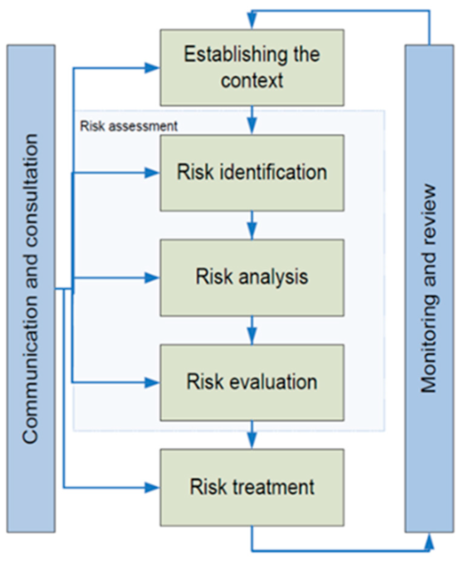
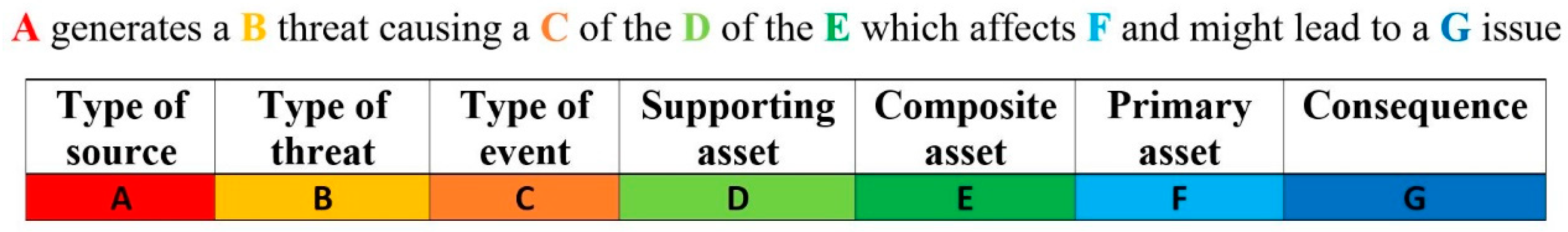
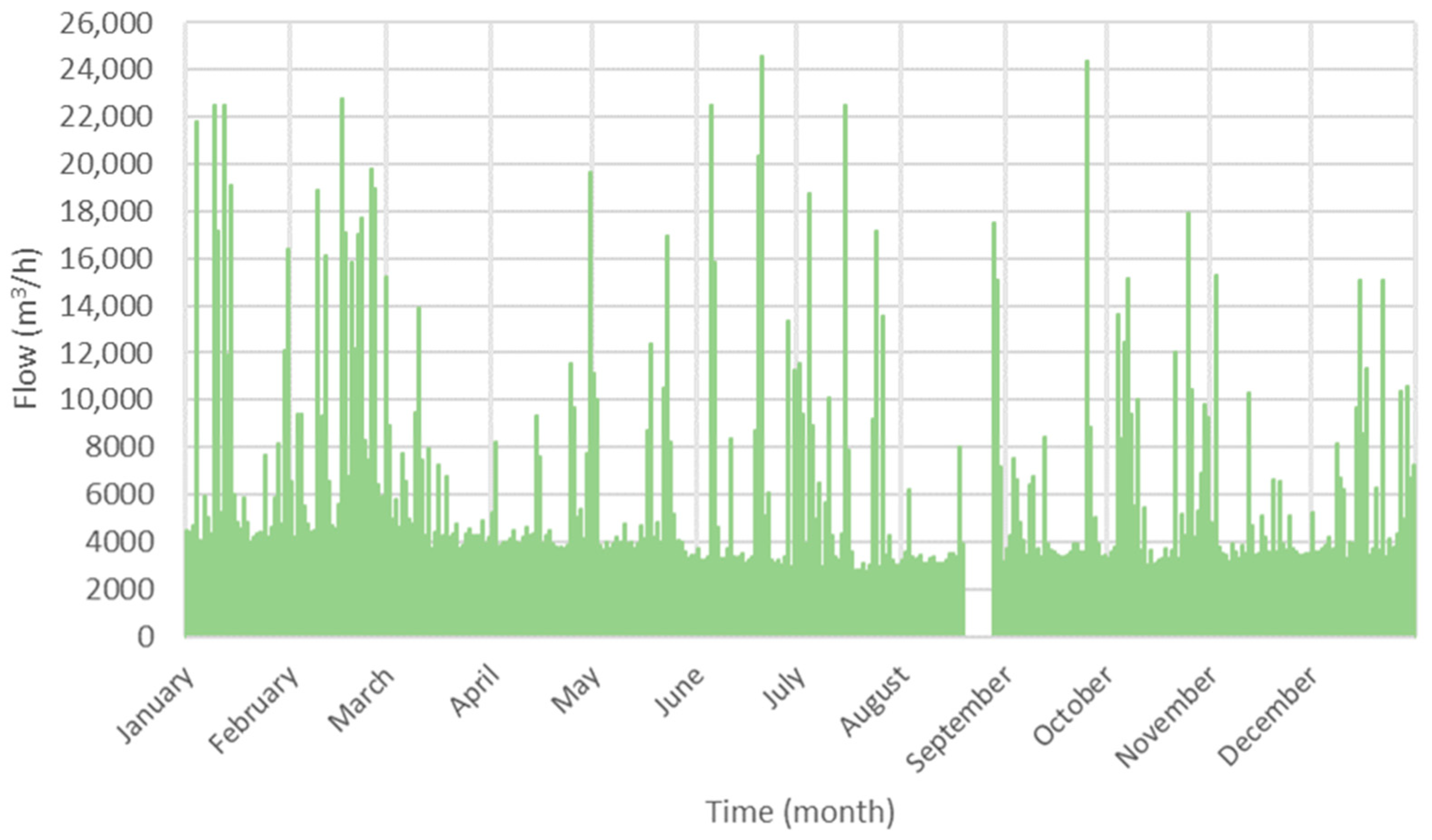
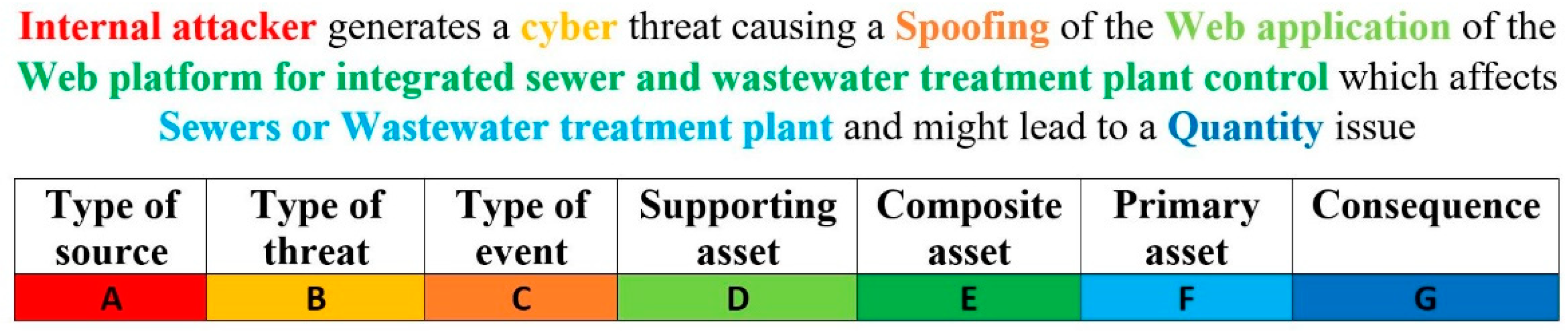
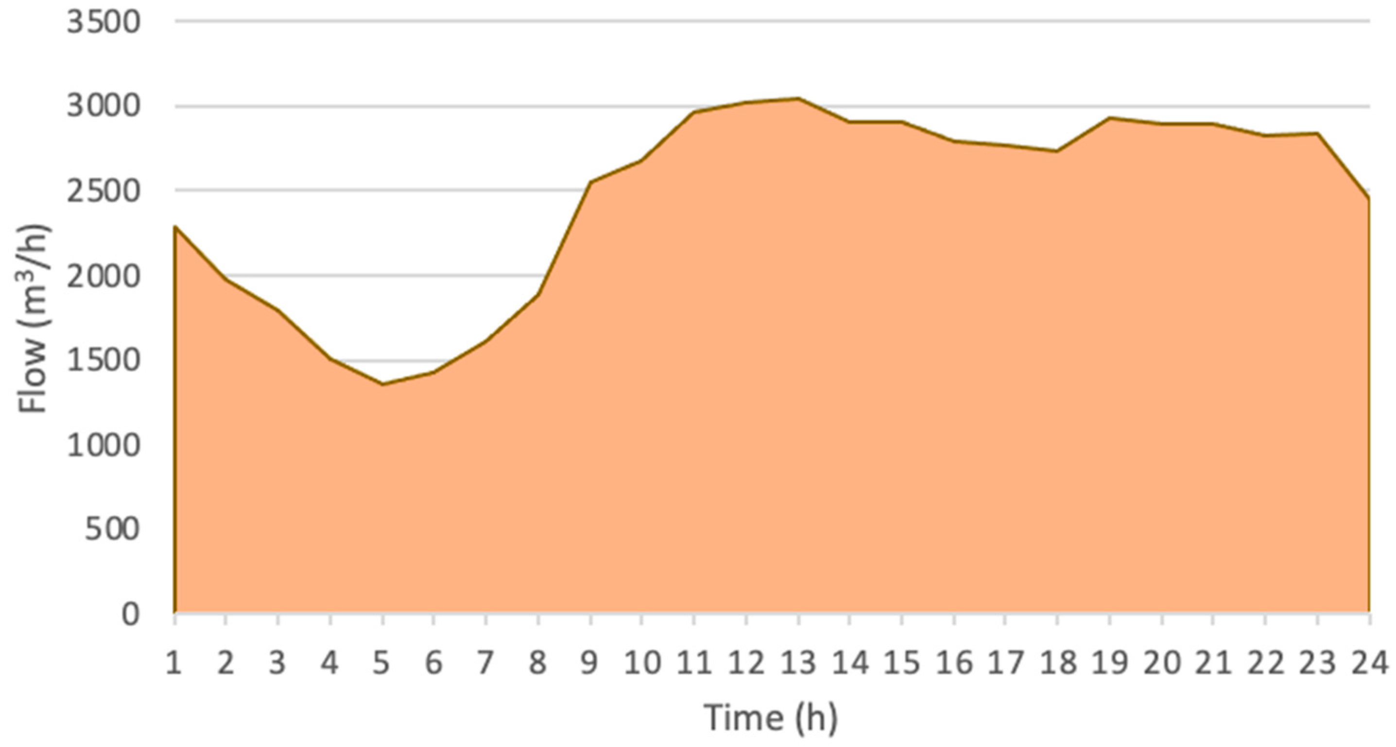
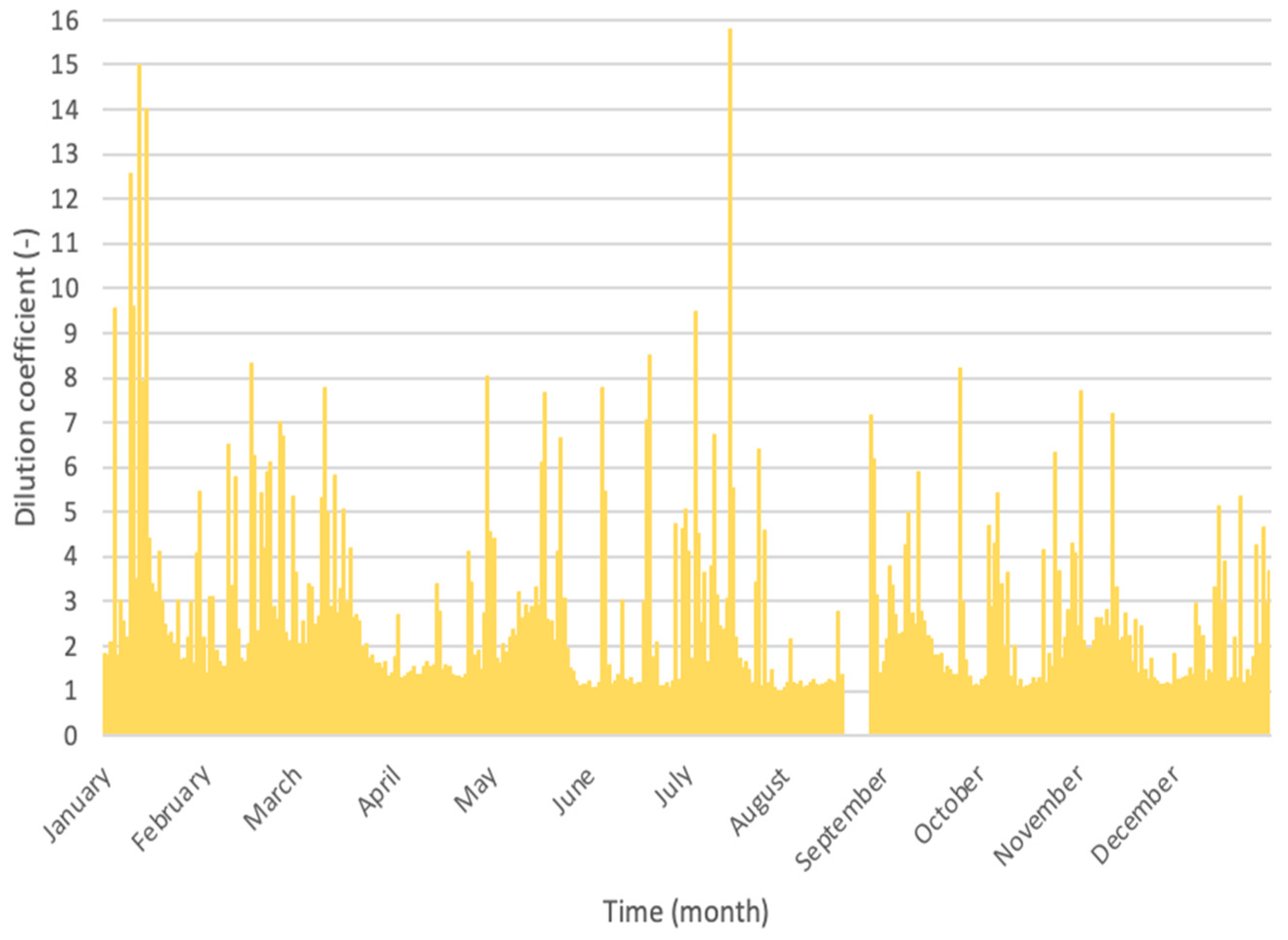
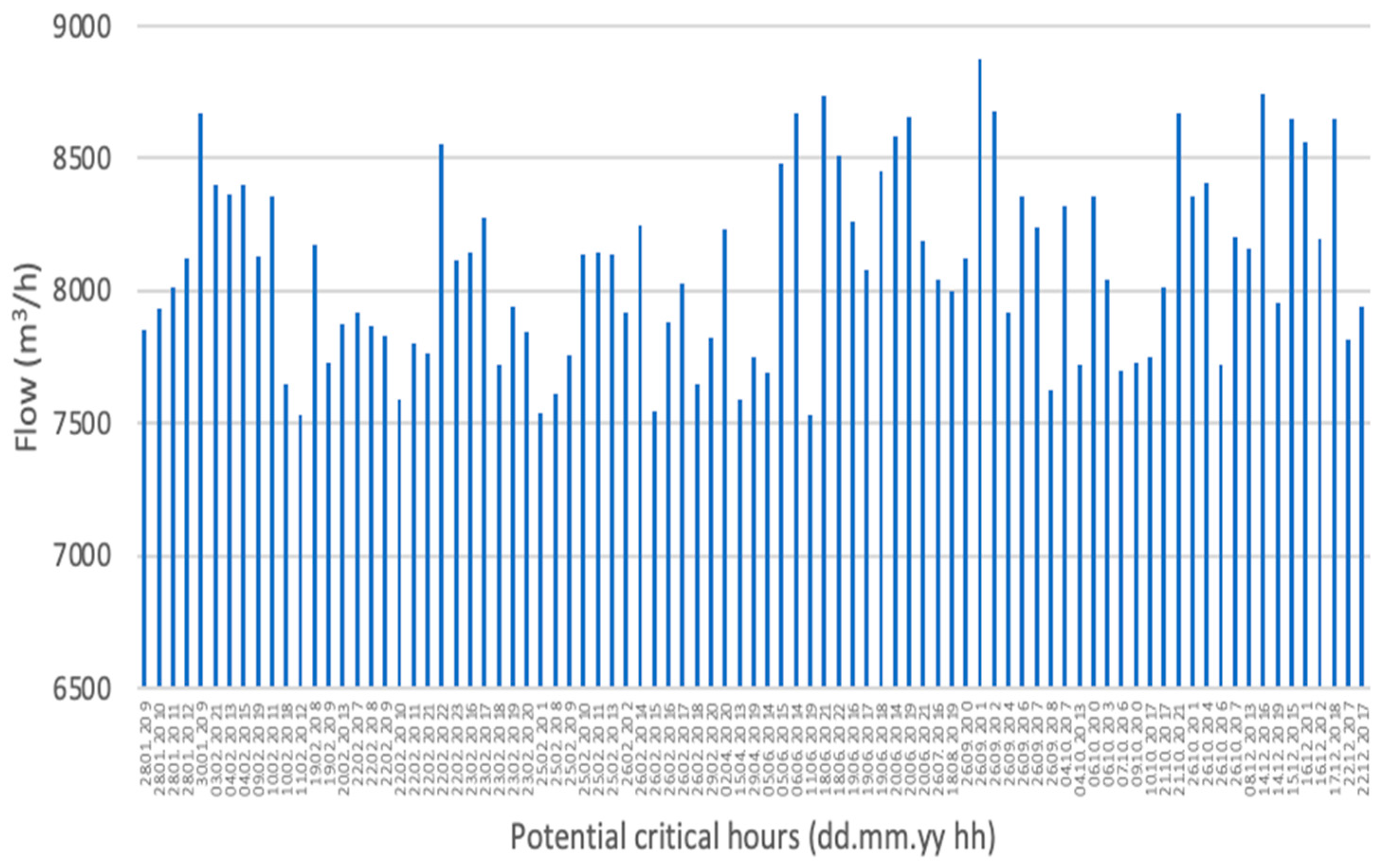
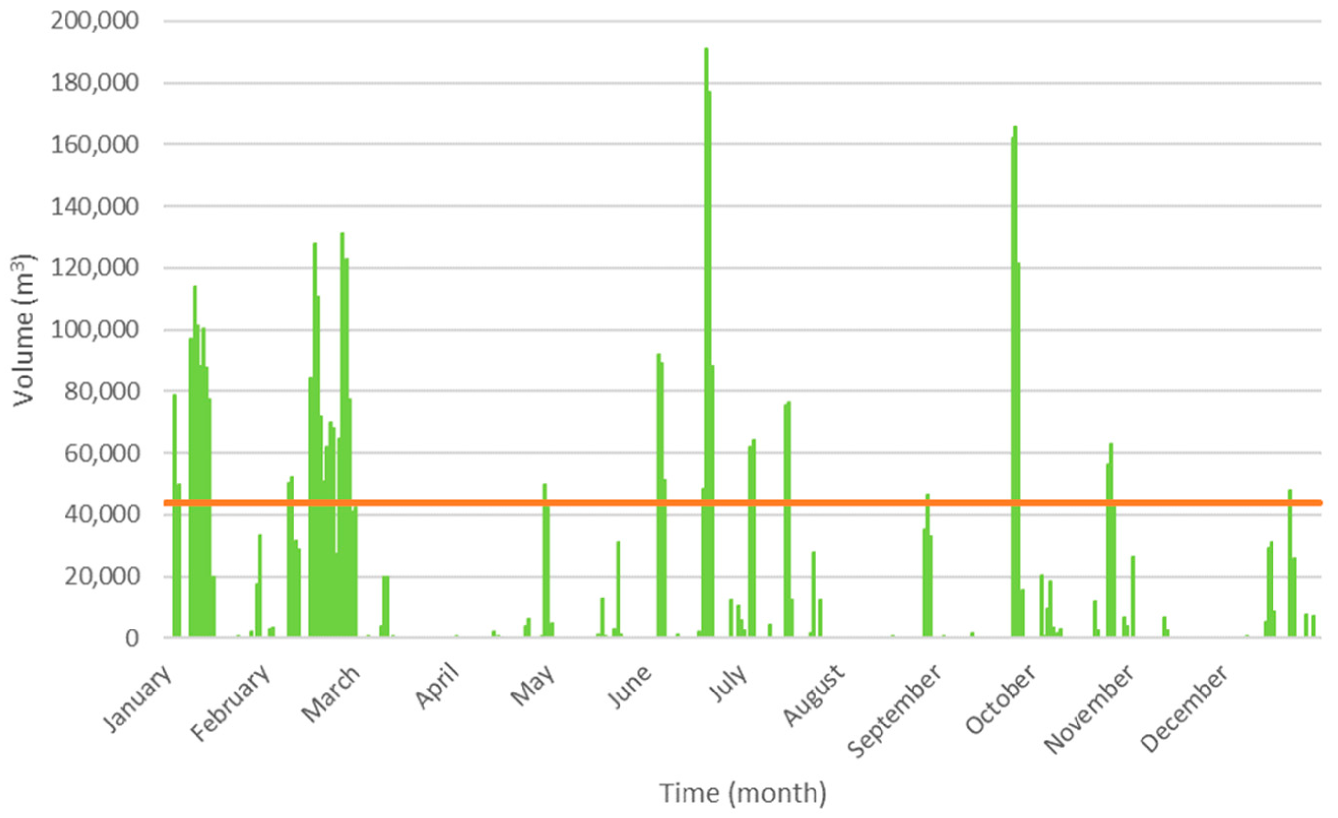
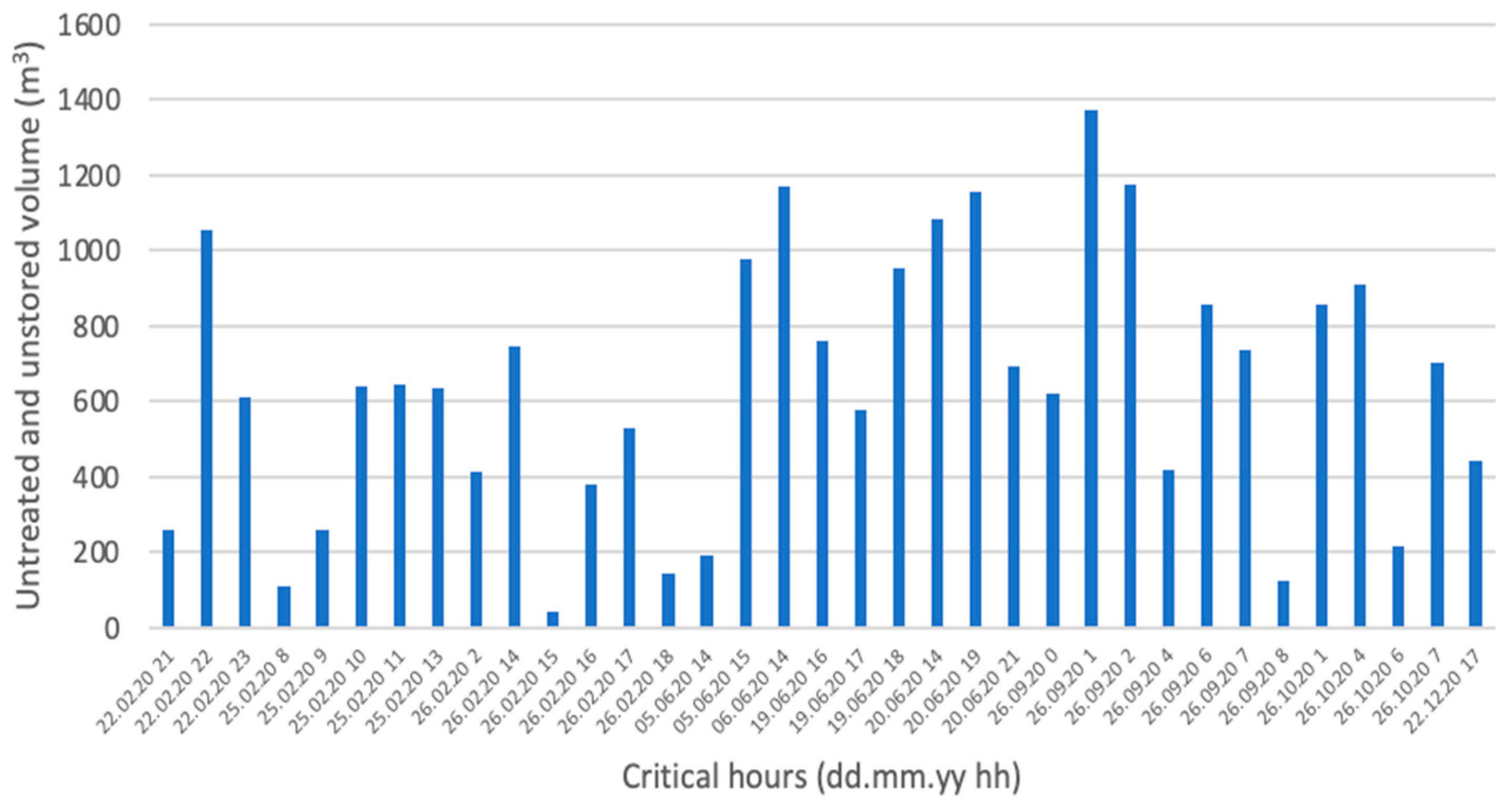
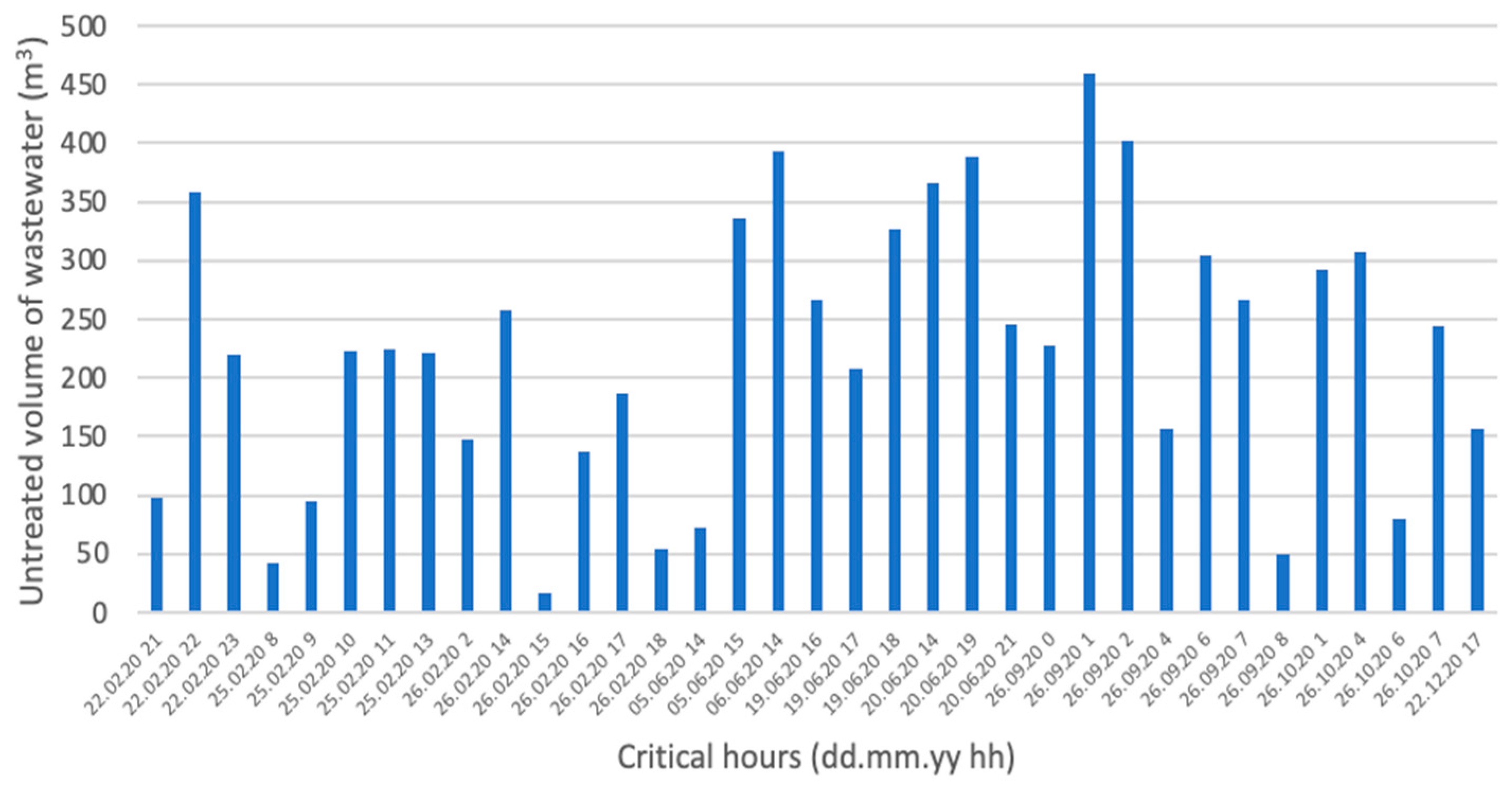
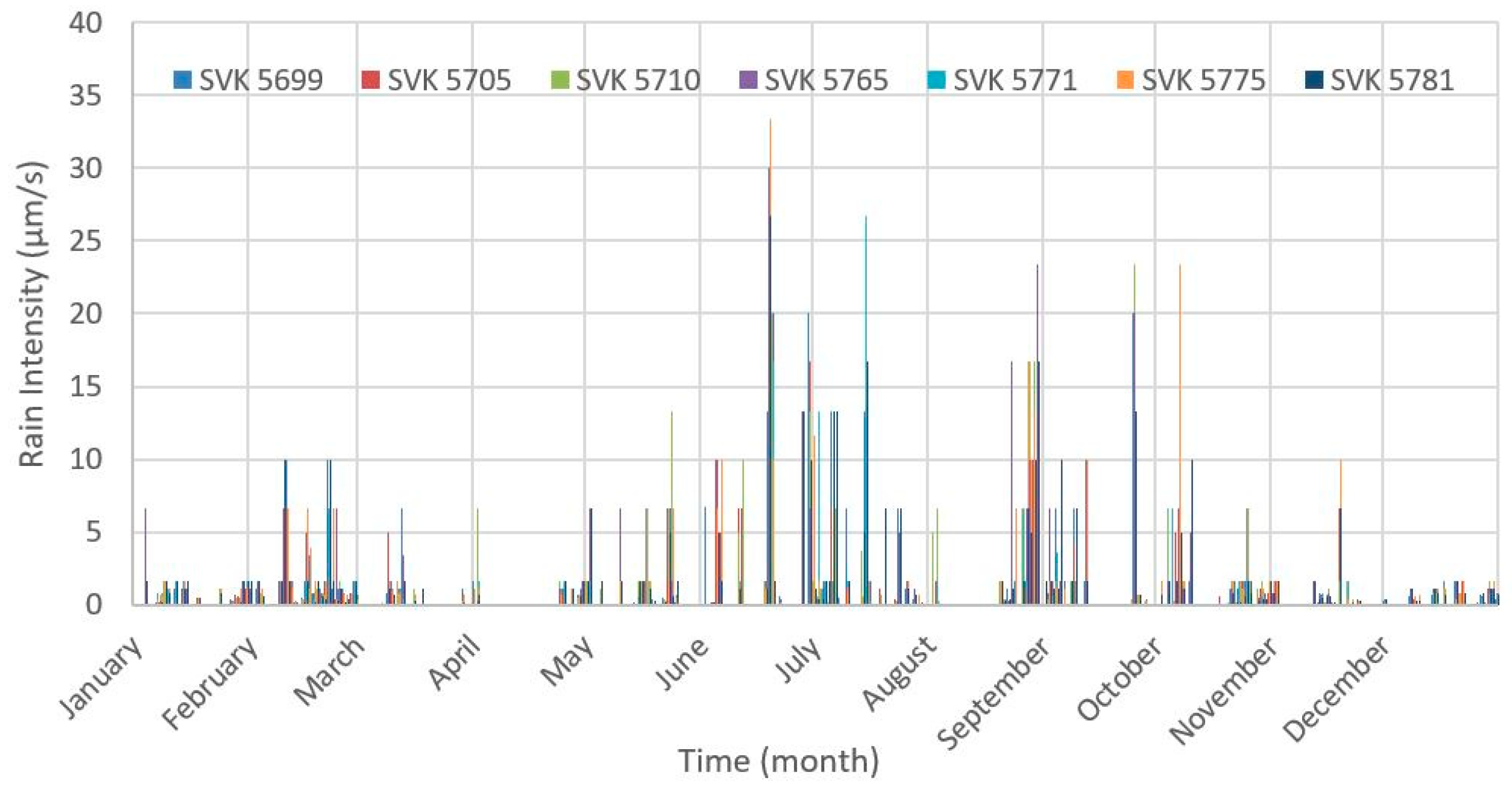
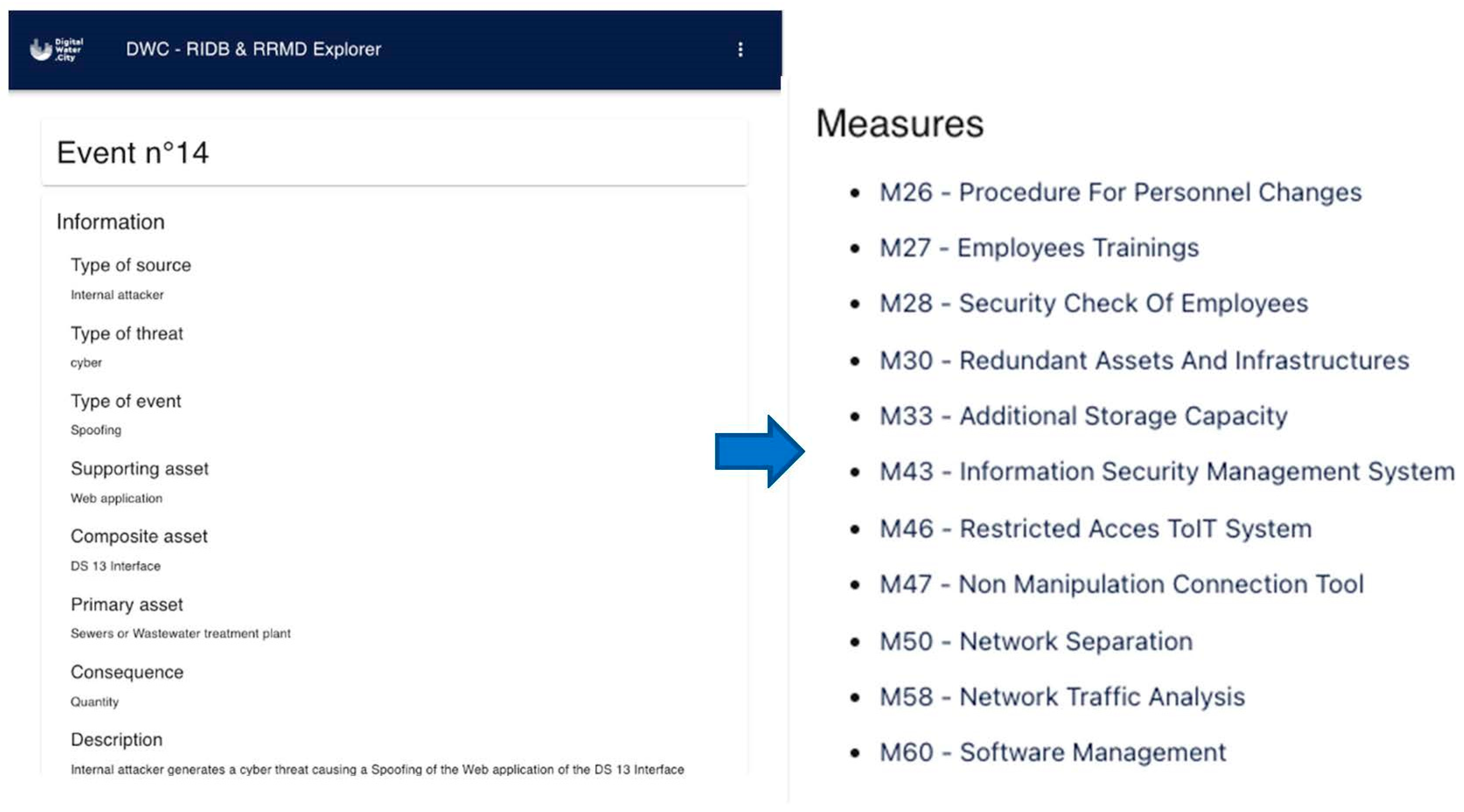
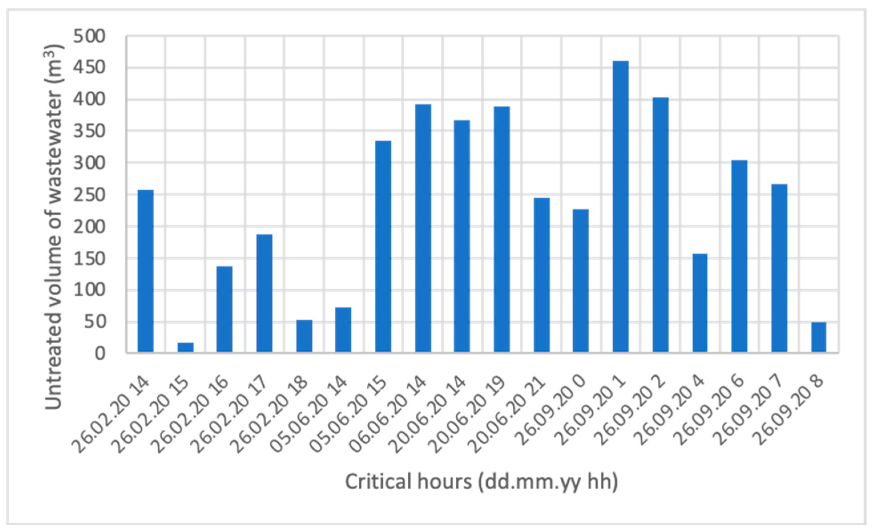
Table 1.
An example of risk matrix with five risk levels, with very low (VL) risk in grey, low (L) in green, medium (M) risk in yellow, high (H) risk in orange, and very high (VH) in red.
Table 1.
An example of risk matrix with five risk levels, with very low (VL) risk in grey, low (L) in green, medium (M) risk in yellow, high (H) risk in orange, and very high (VH) in red.
| Probability (p) | F | M | H | H | VH | VH |
| P | L | M | M | H | VH | |
| O | L | L | M | M | H | |
| R | VL | L | L | M | H | |
| VU | VL | VL | L | L | M | |
| VL | L | M | H | VH | ||
| Consequence (c) | ||||||
Table 2.
Characterization of WWTP loading and effluent quality.
| Parameter | COD | Nitrogen | Phosphorus | Units |
|---|---|---|---|---|
| Inlet concentrations | 680 | 53 | 7.1 | mg/L |
| Plant loading per day | 47,000 | 3700 | 500 | kg/d |
| Effluent required concentrations | 75 | 8.0 | 1.5 | mg/L |
| Effluent concentrations | 32 | 6.1 | 0.6 | mg/L |
| Effluent discharge per day | 2169 | 416 | 42 | kg/d |
| Percentage of pollutants removal | 95 | 89 | 92 | % |
Table 3.
Low risk (in green), medium risk (in yellow), and high risk (in red) as pre-defined levels of risk for the case study expressed in terms of the selected KPI, based on thresholds corresponding to time intervals of 10 and 60 min.
Table 3.
Low risk (in green), medium risk (in yellow), and high risk (in red) as pre-defined levels of risk for the case study expressed in terms of the selected KPI, based on thresholds corresponding to time intervals of 10 and 60 min.
| Low Risk | Medium Risk | High Risk |
|---|---|---|
| KPI ≤ 120 | 120 < KPI ≤ 1200 | KPI > 1200 |
Table 4.
Identification of the level of risk by comparing results with targets values.
| Low Risk | Medium Risk | High Risk |
|---|---|---|
| KPI ≤ 120 No Low Risk: 233 > 120 | 120 < KPI ≤ 1200 Medium Risk: 120 < 233 ≤ 1200 | KPI > 1200 No High Risk: 233 < 1200 |
Disclaimer/Publisher’s Note: The statements, opinions and data contained in all publications are solely those of the individual author(s) and contributor(s) and not of MDPI and/or the editor(s). MDPI and/or the editor(s) disclaim responsibility for any injury to people or property resulting from any ideas, methods, instructions or products referred to in the content. |
© 2023 by the authors. Licensee MDPI, Basel, Switzerland. This article is an open access article distributed under the terms and conditions of the Creative Commons Attribution (CC BY) license (https://creativecommons.org/licenses/by/4.0/).
Share and Cite
MDPI and ACS Style
Bosco, C.; Thirsing, C.; Jaatun, M.G.; Ugarelli, R. A Cyber-Physical All-Hazard Risk Management Approach: The Case of the Wastewater Treatment Plant of Copenhagen. Water 2023, 15, 3964. https://doi.org/10.3390/w15223964
AMA Style
Bosco C, Thirsing C, Jaatun MG, Ugarelli R. A Cyber-Physical All-Hazard Risk Management Approach: The Case of the Wastewater Treatment Plant of Copenhagen. Water. 2023; 15(22):3964. https://doi.org/10.3390/w15223964
Chicago/Turabian StyleBosco, Camillo, Carsten Thirsing, Martin Gilje Jaatun, and Rita Ugarelli. 2023. "A Cyber-Physical All-Hazard Risk Management Approach: The Case of the Wastewater Treatment Plant of Copenhagen" Water 15, no. 22: 3964. https://doi.org/10.3390/w15223964
Note that from the first issue of 2016, this journal uses article numbers instead of page numbers. See further details here.