
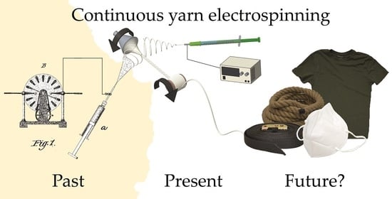
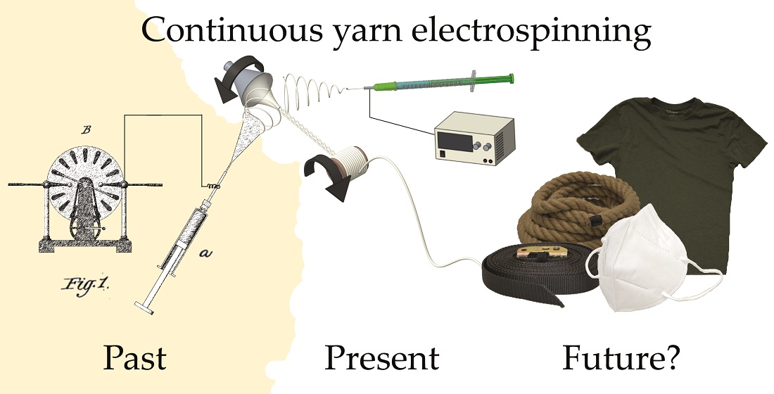
Continuous Yarn Electrospinning


1
Department of Biomaterials, University of Bayreuth, 95447 Bayreuth, Germany
2
Bayreuth Center for Colloids and Interfaces (BZKG), University of Bayreuth, 95447 Bayreuth, Germany
3
Bayreuth Center for Molecular Biosciences (BZMB), University of Bayreuth, 95447 Bayreuth, Germany
4
Bayreuth Center for Material Science (BayMAT), University of Bayreuth, 95447 Bayreuth, Germany
5
Bavarian Polymer Institute (BPI), University of Bayreuth, 95447 Bayreuth, Germany
*
Author to whom correspondence should be addressed.
Textiles 2022, 2(1), 124-141; https://doi.org/10.3390/textiles2010007
Submission received: 22 December 2021
/
Revised: 10 February 2022
/
Accepted: 19 February 2022
/
Published: 23 February 2022
(This article belongs to the Special Issue New Research Trends for Textiles)
Abstract
:Nanofiber-based nonwoven mats produced in electrospinning setups are usually very fragile, which often limits their applicability. Yarns have the potential to enable the incorporation of nanofibers into other materials using well-established techniques such as sewing, knitting, weaving and embroidering, thus broadening the application of nanofibers. Here, we review the development of continuous yarn electrospinning processes. Amongst several possible approaches, funnel-based collector systems have been widely adopted. Here, we summarize recent developments in the field and highlight studies providing visions on how to expand that field of research in future studies of continuous yarn electrospinning.
1. Introduction
Electrospinning is an electrostatic-based technique used to produce ultrafine fibers from the micrometer down to the nanometer scale [1]. It is a simple yet highly customizable process which can be used in conjunction with many systems such as polymer melts [2], polymer solutions [1], sol-gels [3], and even ceramics [4]. Due to the process versatility, electrospun fibers and mats have found potential applications in various fields such as air filtration [5], tissue engineering and drug delivery [6,7], gas sensing [8], material reinforcement [9], and catalysis [10].
Generally speaking, the direct products of the electrospinning process are either one-dimensional as in the case of bundles and yarns, or two-dimensional as in the case of nonwoven mats. Within these two forms, the fiber orientation can be random, aligned, or a mixture of both. Between the two forms, nonwoven mats are arguably the far easier form to produce due to the bending instability that almost inevitably occurs during the extension of the electrostatically generated jets (Figure 1), which results in the random deposition of solidified fibers on a surface. Thus, the manufacture of electrospun mats does not require an elaborate setup.
Electrospun yarns on the other hand are more difficult to produce. Once the jet has been generated from the liquid reservoir—typically the tip of a needle—the challenge is to ensure the alignment of up to thousands of tiny, solidified fibers into a bundle before the fibers touch and adhere to a surface, then twisting the bundle into a yarn in a controlled manner. For the past two decades, various groups have come up with different techniques for producing electrospun yarns of different composition and qualities. We will see that one particular method and its variants have been used repeatedly by different groups. However, as these works were dictated by their own specific research interests and applications, the experiments were not conducted in such a way that the results are easily comparable.
There had so far been several reviews on the topic of yarn electrospinning [12,13,14,15], though none of them specifically discussed the problem of direct comparison between the various methods. If yarn electrospinning is to be a method that is widely adopted, researchers should be able to decide which methods are the most suitable for their own application based on certain parameters such as production speed, fiber fineness, yarn fineness, and fiber mechanical properties. Additionally, one widely available polymer that is easily electrospun should also be used as a standard polymer whose characterization allows the comparison between various yarn electrospinning setups.
2. Continuous Yarn Electrospinning
The phenomenon known today as electrospinning has been known as early as the 19th century. One account was given in 1887 by CV Boys, in which he described the behavior of organic melts on an insulated dish subjected to high voltage. Upon reaching the edge of the dish, the droplets of the melt could be observed flying away from the dish, leaving a trail of fibers in their path. He further observed a rosy shade on a piece of paper when sealing wax was used, attributing it to “innumerable fibres separately almost invisible”, possibly the first account of an electrospun nonwoven mesh [16].
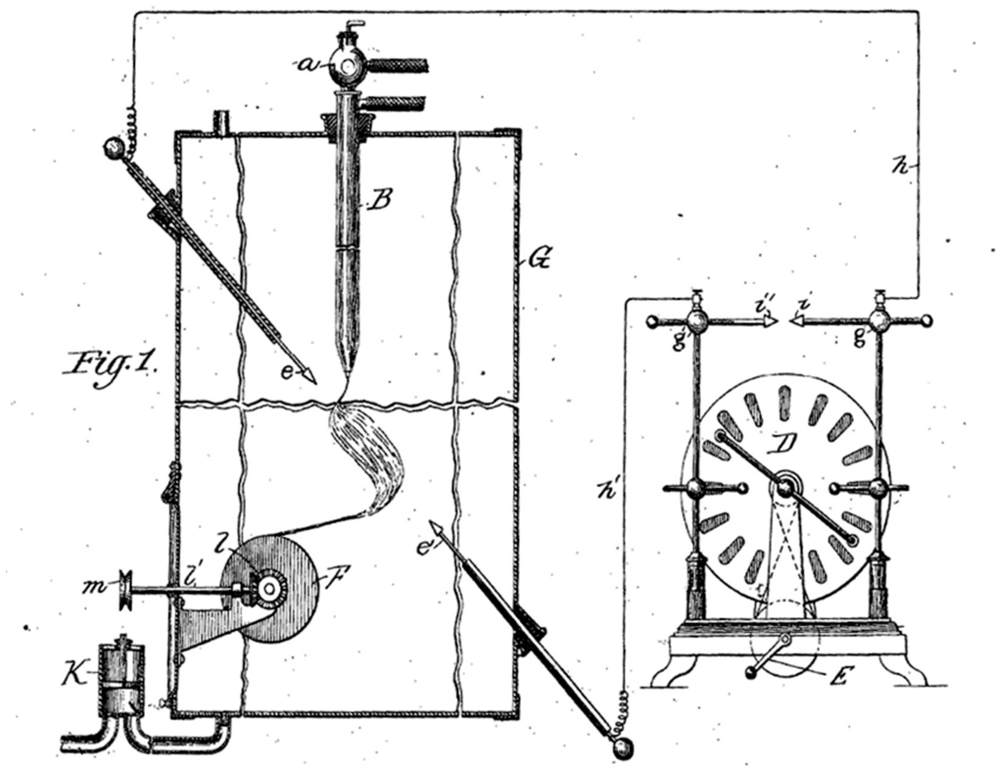
The first patent concerning fiber electrospinning, according to Tucker et al. [17], was published in 1900 by Cooley [18]. Arguably, this was also the first patent on the continuous electrospinning of fiber bundles, the schematics of which is seen in Figure 2. The patent describes the delivery of the spinning solution by means of a glass capillary (B) into the electric field generated by two electrodes (e and e’) charged to a high voltage by using e.g., a Wimshurst machine (D), a common high voltage generator at that time. Interestingly, the electrode does not need to directly contact the spinning solution. Instead, the solution gets charged in mid-air upon entering the electric field and dispersed into smaller streams that, upon evaporation of the solvent, solidify into fibers, which are attracted to the opposite electrode. By intercepting the fibers using a glass rod (not shown in the schematics) and bringing them onto a reel (F), the fibers can be continuously collected. The electrospinning takes place in an enclosure (G) which can be evacuated using a pump (K). The evacuated atmosphere can then be treated to recycle the evaporated solvent. Apart from the modernization of most of the components used by Cooley, the general principle and arrangement of the electrospinning setup have remained unchanged since then.
In 1934, a particularly prolific inventor named Anton Formhals published his first patent [19] on electrospinning. During the following decade, he published at least another 21 patents [17] on the subject. His inventions consisted of various improvements on the electrospinning method, especially those concerning the upscaling of the method, including the use of multiple spinnerets and conveyor belts to collect and transport the fibers.
It was not until the early 1990s that “electrospinning” as a term was popularized by several research groups such as that of Reneker [1]. The introduction of a single word to denote the phenomenon of fiber formation through electrostatic jetting of fluids facilitated the discussion of the subject. Combined with the advent of nanotechnology, the interest in nanoscale materials, including electrospun fibers, increased rapidly. Since then, the number of publications has grown exponentially. Over the past two decades, many researchers have used different techniques to produce nanofiber mats and yarns.
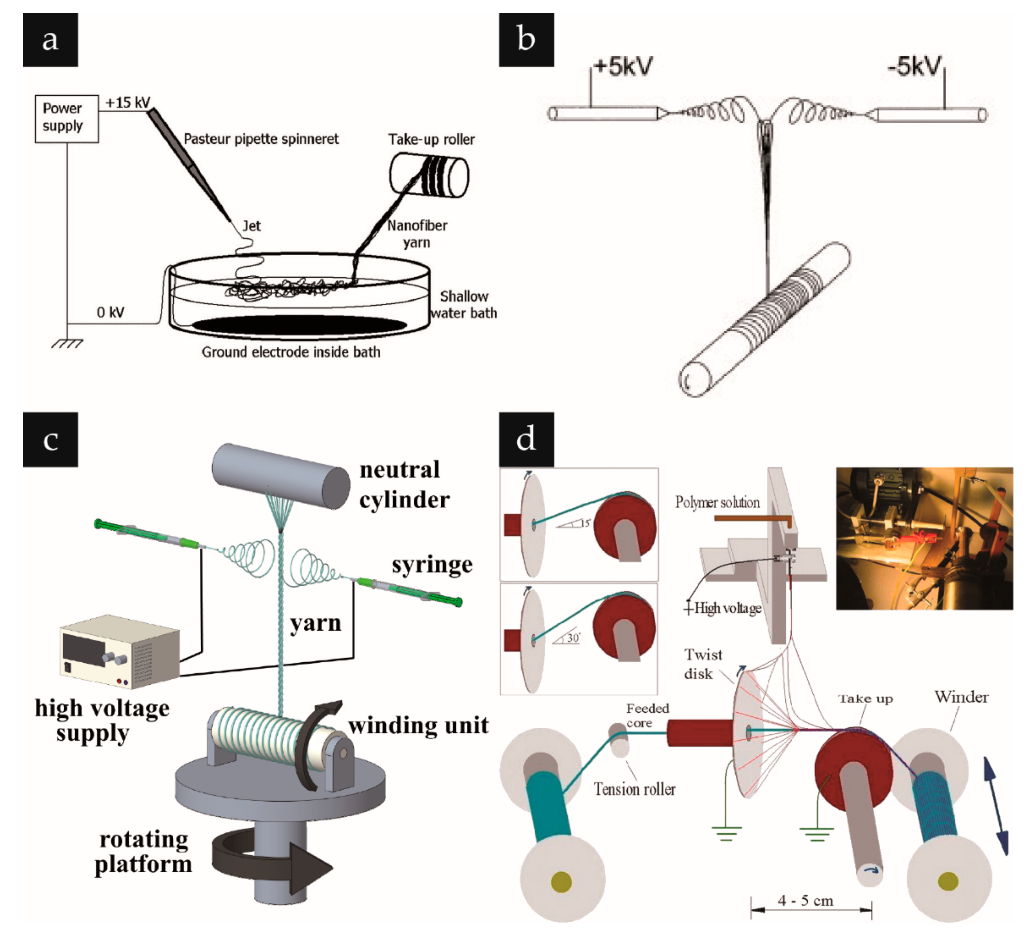
Many research groups cited the difficulty in handling nanofibers as a motivation for developing systems to produce electrospun bundles and yarns [20,21], which, due to the distribution of load among the constituent fibers, increases the robustness of the fibers. Initial efforts towards realizing such setups tended to be systems enabling fiber bundle production. This was achieved through various means. Water-based collectors (Figure 3a), such as used by Smit et al. [22] and Teo et al. [23], rely on water’s fluidity to help realign the fibers. As the collector surface is not stiff, the fibers can be pulled on one end without the fibers experiencing too much tension that would break them due to their adhesion to the collector surface, as is the case with a solid collector. As the fibers are pulled out of water, surface tension pulls them together into a bundle. Other works, such as those from Pan et al. [24] (Figure 3b), rely on opposite charges to align the fibers. One or several pairs of nozzles charged with opposite voltages are pointed towards each other, such that the jets that emanate from the nozzles are attracted to each other. This partially cancels out the whipping motion caused by the bending instabilities and aligns and bundles the fibers together. The bundles can then be easily captured using an insulated rod and brought to a motorized winder for automatic collection.
True yarns, however, contain twists, which require an extra step or element to be incorporated into the electrospinning system. This can be done in several ways. One approach is to rotate the winder itself, meaning that, in addition to the winding action of the winder, the winder is placed on a rotating platform, through which the twist in the yarn is achieved as seen in the work of Maleki et al. [25] (Figure 3c).
Another approach, taken by Bazbouz et al. [26], used a rotating disk onto which the fibers are jetted. A hole in the middle of the disk permits the passage of a core thread, which is unwound on one side of the disk and wound on the other side of the disk. By the spinning of the disk, the electrospun fibers are continuously twisted around this core thread, and the winding of the core thread ensures constant material removal. This results in the continuous production of a core fiber sheathed in electrospun fibers (Figure 3d).
A particularly popular approach involves a rotating funnel to twist fiber bundles into yarns and a winder to collect the yarns. In one of the simpler versions of this method (Figure 4a), a single nozzle is used to convey the spinning solution. This nozzle is connected to a high voltage supply and is pointed at an angle towards a rotating circular or annular geometry, which in turn is pointed towards a winder. When the spinning solution is pumped through the nozzle and high voltage is applied, fibers land across the opening of the funnel, eventually forming a nonwoven mat covering the funnel opening. By bringing the tip of an insulated rod close to the nonwoven mat, some of the freshly formed fibers will land both on the tip and the mat, forming a connection. With sufficient material bridging between the tip and the mat, the mat can now be deformed into a nonwoven cone by pulling the rod away. The rotation of the funnel twists the cone into a yarn, which steadily extends in length from the tip of the cone as the rod is pulled further from the funnel. If the yarn is now brought towards a mandrel on a motorized winder, material will be continuously removed from the cone, while the nozzle continuously deposits fibers onto the cone. With the correct configuration, a mass transfer equilibrium takes place, the cone retains its shape, and the process can be run continuously. This approach has proven quite successful in continuously producing yarns, such that many groups have adopted or modified it for their own works, as will be discussed in the following.
3. Variations of the Rotating Funnel Collector System for Yarn Electrospinning
Figure 4 shows the schematic drawing of the setup used in selected works, which is based on the general principle of using a rotating funnel for the simultaneous deposition and twisting the electrospun fibers into a yarn and a motorized winder that collects the yarn. In its simplest form, the setup involves only four major components: A single nozzle for material extrusion and jetting, a high voltage source, a grounded rotating funnel collector, and a motorized winder, as used by Afifi et al. [27] in an early work from 2010 (Figure 4a).
A subsequent, two-nozzle variation is especially widespread and has been adopted in various works [28,29,30,31,32,33]. The first nozzle is arranged opposite to the second, with both nozzles most commonly being charged with opposite voltages (Figure 4b), although some authors, e.g., Jin et al. [29] and Tong et. al. [32], used the same charge for both nozzles. Electrospinning using a pair of nozzles with opposite charges is termed “conjugate electrospinning” [34]. This setup comes with several advantages. Using two nozzles is a straightforward way to double the material throughput, which increases yarn production speed. Because the two electrostatically generated jets neutralize each other’s charges, earthing the funnel is not necessary. Positioning the nozzles opposite to each other ensures an even material distribution on the funnel and the subsequently formed nonwoven cone, which is important in ensuring that the cone retains its shape by evenly replenishing material at the same time as material is being continuously removed by the winding unit. To further increase throughput, multiple pairs of nozzles can be arranged around the funnel, as was demonstrated in the 2013 work of He et al. [35], in which two pairs of nozzles were used and a subsequent work in 2014 by He et al. [36], where four pairs of nozzles were used.
The geometry of the rotating object, which imparts the twist in the yarn, does not strictly have to be a funnel. Wu et al. [30], for example, used a setup almost identical to the one used by Li et al., exchanging the funnel with a spinning metal disc (Figure 4c). Shuakat and Lin [37] went further and showed that, in essence, the geometry only needs to be circular. Instead of a funnel, they used a ring and under it they positioned a contacted rotating disc. The lower part of the disc was partially immersed in the polymer solution bath and, as the disc turned, the solution was continuously transferred to the upper part of the disc, where multiple Taylor cones formed and supplied the ring with freshly formed fibers, which were then twisted into a yarn by the rotation of the ring and subsequently rolled by the winding unit above. This setup greatly increased the throughput of the yarn electrospinning process.
Another interesting variation of the funnel-based setup is seen in the work of Yang et al. [38], who used a single nozzle as Afifi et al. [27], but introduced a variation in the winder. The motorized winder was mounted on a slider, which oscillated the winder uniaxially. This distributed the yarn over the length of the winder mandrel. The winder was placed close to the rotating funnel, such that the jets landed both on the funnel and on the mandrel. This resulted in yarns interlaced with randomly ordered nonwoven mats (Figure 4d).
Figure 4.
Variations of yarn electrospinning setups using a funnel. (a) The simplest variation of such setup is the one used by Afifi et al. Reprinted with permission from Ref. [27]. Copyright 2010 Wiley. (b) Li et al. used two nozzles, doubling the throughput and stabilizing the nonwoven cone forming on the rotating funnel. The oppositely charged nozzles made earthing the funnel no longer necessary. Reprinted with permission from Ref. [28]. Copyright 2020 American Chemical Society. (c) Wu et al. used a disc instead of the funnel in combination with a guiding metal rod. Reprinted with permission from Ref. [30]. Copyright 2013 Elsevier. (d) Yang et al. used a winder placed on a slider to distribute the yarn along the winder mandrel to produce a combination of yarns and randomly oriented fiber mat. Reprinted with permission from Ref. [38]. Copyright 2014 Elsevier.

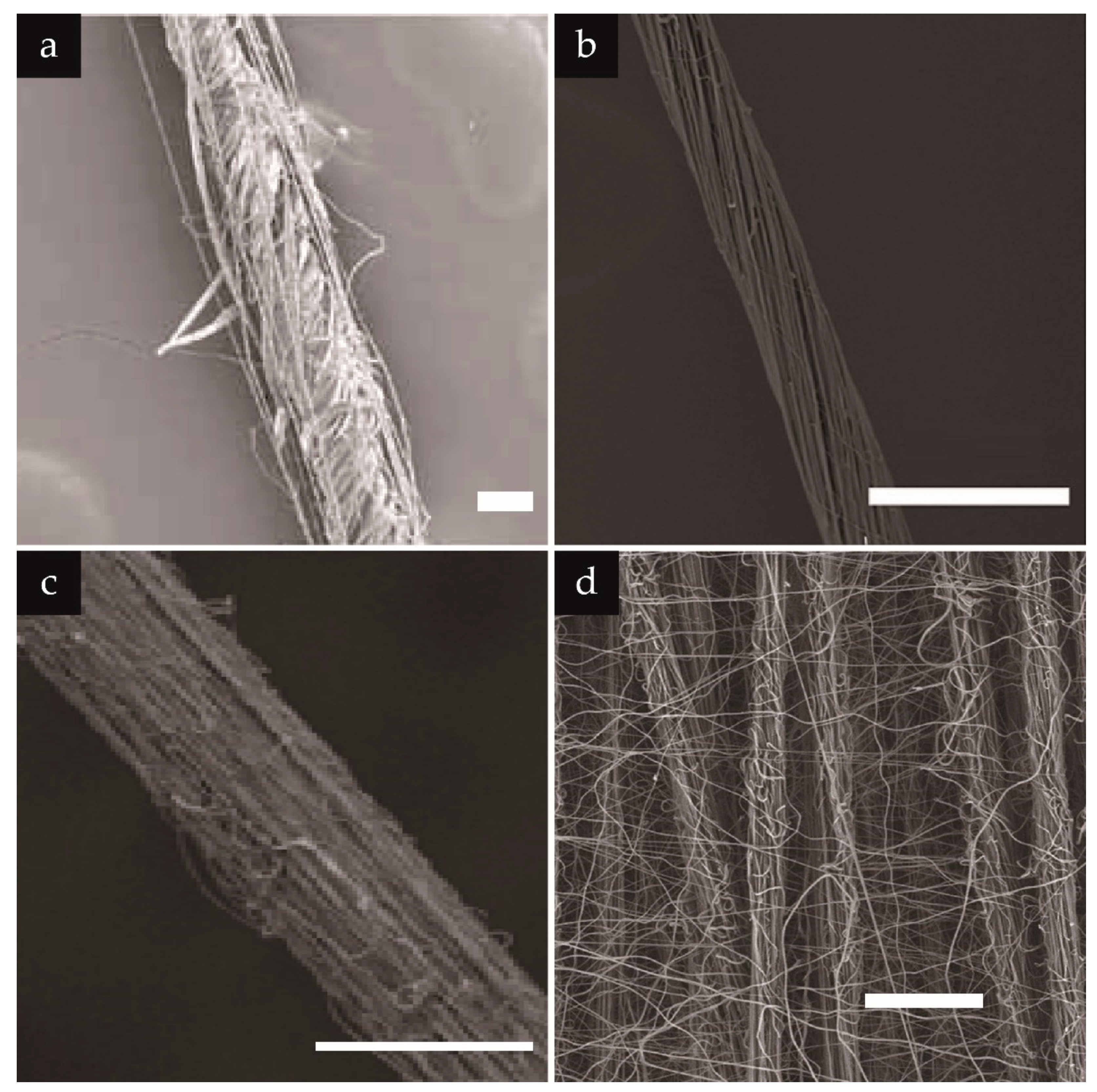
These strategies all resulted in the formation of yarns, whose qualities differ in terms of alignment, yarn hairiness, and uniformity of diameter. In contrast to the previous works reported in the 19th century and the early half of the 20th century, these recent works included SEM images of the resulting yarns to demonstrate the quality of their process. As examples, we included in Figure 5 the SEM images corresponding to the experimental setups shown in Figure 4.
Figure 5a shows the result of the work of Afifi et al. [27]. Here, the twist can be seen in the fibers in the core of the yarn, but some fibers on the outside laid straight along the yarn length. The yarn diameter therefore was ill-defined along the yarn length. Many individual fibers could be seen protruding out of the yarn. In contrast, Li et al. [28] produced yarns with highly aligned fibers and apparent twist. The yarn depicted in the SEM image also had a uniform diameter, and fibers could be seen protruding out of the yarn (Figure 5b). Only some occasional fibers could be seen winding around the yarn in a disordered manner. Wu et al. [30] produced a yarn of intermediate quality. The yarn diameter appeared uniform along the yarn length. However, the twist was not apparent, and individual fibers were loosely packed in the main yarn body. Yang et al. [38] had a slightly different goal, thus the perfect containment of individual fibers within a single yarn was not as important. Instead, the construct was a mixture of yarns with randomly arranged fibers laid on top of them (Figure 5d). Overall, funnel-based yarn electrospinning proved successful in continuously producing yarns.
4. Electrospun Biogenic Polymer Yarns
Biogenic polymers are polymers produced or derived from compounds of living organisms. Apart from the independence from traditional sources of polymers, i.e., petroleum, biogenic polymers present an interesting class of materials because of their properties, such as biodegradability in most cases, making them attractive in terms of environmental sustainability [39]. Many biogenic polymers are also biocompatible and thus suitable for medical applications [40]. Polypeptide or polysaccharide-based polymers occur either naturally such as cellulose, alginate, and collagen or are produced recombinantly such as recombinant collagen [41], elastin-like polymers [42], and spider silk proteins [43].
Biogenic fibers are widely used in many applications, cellulose and wool, for example, in human clothing for millennia. Regeneration of biogenic polymers liberates them from being constrained to the form imparted to them by biological systems. Thus, we can have biogenic polymers such as spider silk, which naturally occurs for the most part as fibers, in forms never occurring in nature such as films, hydrogels, and foams [44]. In this context, the production of electrospun biogenic polymer nanofibers has been investigated. [45,46,47,48,49] However, despite their wealth of potential in future applications, as well as their demonstrated electrospinnability, there seems to be a lack of data in continuous electrospinning of yarns based on biogenic polymers. Most work in literature so far focused on synthetic polymers. We, therefore, utilized continuous yarn electrospinning on biogenic polymers and characterized the properties of the resulting yarns.
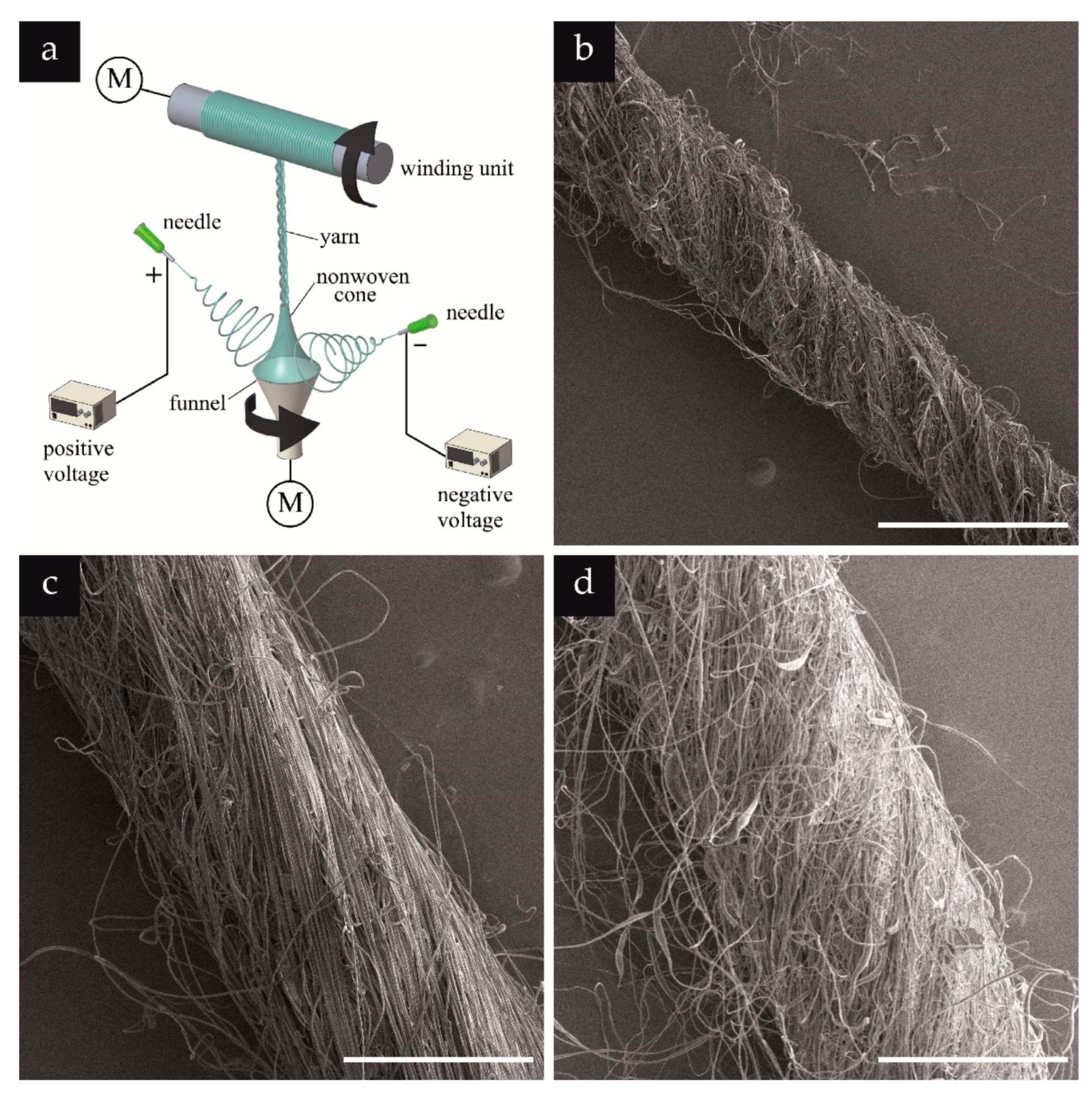
Here, we electrospun yarns made of cellulose acetate and the recombinant spider silk protein eADF4(C16) by using a conjugate electrospinning setup adapted from the one used by Li et al. [28]. Minor adjustments of the setup included the vertical arrangement of the funnel and the placement of the winding unit above the funnel (Figure 6a). Each needle (of size 21 G) was clamped to an electrode wire with crocodile clamps. The needles were pointed towards the funnel at an angle of about 30° from the horizontal plane, and were positioned, each on one side of the funnel, between 3 and 5 cm horizontally and between 2 and 4 cm vertically away from the middle of the funnel. The funnel (5 cm in diameter in the opening, 3 cm in diameter in the lower part, and 5 cm high) was connected by a polymer shaft to a motor, which rotated at 200 rpm. The voltage used was between +4 and +7 kV on one needle and between −4 and −7 kV on the other. The flow rate used for feeding the solution into each needle was 10.5 µL/min. At the start of the process, the motor connected to the funnel as well as the syringe pump were turned on. As soon as a droplet formed at each needle, the high voltage was turned on. Fiber bundles formed at the space above the funnel, part of which were also adhering to the funnel. These were fished up using a polymer rod and were led onto the motorized winding unit placed vertically above the funnel. The motorized winding unit was then turned on and set to rotate at 6 rpm (roll diameter = 10 mm). For morphological characterization, the collected yarns were then sputter coated with platinum (1.2 nm thick) and analyzed using SEM at magnifications of 250×–15,000× at a voltage of 2 kV and working distance of about 8 mm. For tensile testing, the yarns were twisted manually to improve the adhesion between the individual fibers. The yarns were then fixed onto frames with a gauge length of 10 mm and pulled at a rate of 1 mm min−1, measuring the load and displacement as a function of time. These were then plotted onto a stress–strain diagram, with the stress being calculated by dividing the load by the diameter of the yarn, determined using light microscope images.
Concerning morphology, the yarns showed remarkably uniform diameters along their lengths even with manual twisting. The yarns tended to be hairy with individual fibers easily disentangled from the main yarn body when in contact with adhesive surfaces, which can be either an advantage or a disadvantage depending on the application. For example, in composites, a hairy yarn embedded in a matrix may prove advantageous due to the increased surface interaction between reinforcement and matrix, compared to smooth yarns [20]. Examples of an eADF4(C16), cellulose acetate, and PAN (as a control) yarn are shown in Figure 6b–d.
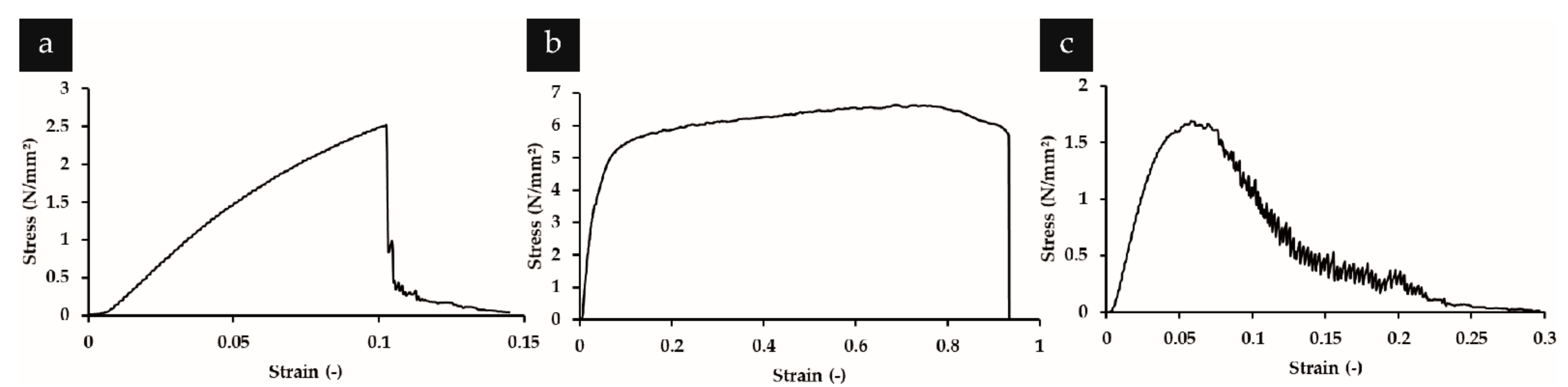
Concerning physical properties, the yarns were able to be handled by hand, and it did not require excessive care to prevent the yarns from rupturing. It was possible, for example, to tie a knot using the yarns. Some inconvenience did arise in handling the yarns as they were very light, and the weight of a stretch of yarn was not enough to cause them to dangle vertically due to gravity as a typical thread would; instead, an unfixed end would float about in the air. The yarns also tended to be highly attracted to surfaces, such that it was very difficult to place short lengths of yarn in a Petri dish and let them go, as they would continue to be attracted to the objects used to handle them (such as a pair of tweezers). Typical stress–strain curves of the yarns are shown in Figure 7a–c. Yarns of each polymer showed their own distinct behavior. The PAN yarns showed a steep elastic region, followed by an extended plastic region and a sudden drop in stress when the fibers in the yarn appeared to break unison. The eADF4(C16) yarns showed a brittle behavior with a very short plastic deformation regime. Upon rupture, the stress dropped abruptly, although not until zero, but until a low value. Possibly, several surviving fibers that still held together the two ends of the partially-torn yarn accounted for the residual tensile stress, which eventually diminished completely as they either slipped or tore. The cellulose acetate yarns showed most clearly the gradual disentanglement of the individual fibers in the yarn through the very gradual fall in tension after a maximum had been reached. The tensile strength and elongation at break of the yarns are summarized in Table 1.
5. Production Speed and Nanofiber Yarn Properties
Production speed is one of the most important factors dictating whether a process can be feasibly implemented at an industrial scale. The throughput limitation is a long-known issue that hinders the implementation of electrospinning for most applications at large scale. In a basic electrospinning setup, the polymer solution or melt is fed through a nozzle. The flow of material is limited by the Taylor cone, whose diameter is much smaller than that of the droplet that forms at the nozzle tip. While this tiny diameter enables the formation of tiny fibers, which sets electrospinning apart from other conventional fiber processing methods, it also turns out to be the limiting factor which makes electrospinning a very low throughput process. Therefore, we have seen various strategies [50] developed to overcome this problem, ranging from the use of multiple needles [51] to abandoning needles altogether and using solution-wetted objects of various geometries [52] to increase the number of Taylor cones forming at the same time.
Here, production speed is the rate of yarn collection, which, in the case of funnel-based continuous yarn electrospinning, is determined by the linear speed of the yarn winder. Earlier works, such as those from Afifi et al. [27] and Dabirian et al. [53], are characterized by low production speeds, using a single needle and achieving production speeds in the cm min−1 range. Many later works using a two-needle approach achieved higher production speeds in the m min−1 range such as those from Ali et al. [31], Li et al. [28], and Wu et al. [30]. While increasing the number of needles enables a higher flow rate at the needles, this does not guarantee a higher yarn production speed, which is determined directly by the winder speed. On the other hand, increasing the winder speed increases the risk of tearing the nonwoven cone, which would halt the production, as connection between yarn and funnel would need to be re-established manually. It appears that optimization plays a large role in dictating the production speed, which explains the large variation in the collection speed between works using the two-needle setup.
Nevertheless, literature shows a progression of increasing production speed by increasing the throughput in a series of works from He et al., who started with two pairs of needles [35], followed by another work using four pairs of needles, then yet another using two pairs of larger nozzles with an inner diameter of 16 mm [54], which extruded polymer solution and air bubbles coaxially, such that multiple Taylor cones could form on the bubble surface. Thus, the production speed progressed from 2 to 4 to 5 m min−1. The move away from a needle-based electrospinning can also be observed in the work of Shuakat and Lin [37], where they used a combination of a needle and a disc, achieving a production speed of 4 m min−1, the second highest among the works that we surveyed. Curiously, the highest production speed of 5 m min−1 found in literature was achieved both by Ali et al. using a needle-based approach, and by He et al. using a needleless approach. However, based on the large diameter distribution of the generated fibers from the work of Ali et al. [31], it can be concluded that a needleless approach is more suitable in achieving a narrower fiber diameter distribution, which lies well below 1 µm.
In addition to the production speed, dimensions of fibers as well as the tensile properties vary greatly between various groups working with the same technique on the same material. Taking PAN as an example, and comparing values reported in MPa, tensile strength values of 8.60 ± 3.03 MPa were achieved in our experiments. In contrast, the highest reported values, which ranged between 100–180 MPa, came from the study of Yan et al., who used a single needle with a collection speed of 8.6 cm min−1, which is among the lowest collection speeds reported. The compiled data reveal a high variability in yarn properties even between works that utilized similar techniques, highlighting the importance of optimizing a setup to achieve the best results.
Until quite recently, most yarns have been made out of microfibers. While these have been useful for many different applications, it has been quite unknown how yarns of certain materials would behave, if their constituent fibers are made of nano- instead of microfibers. Recent works are beginning to probe the properties and behavior of nanofiber yarns in traditional textile scenarios such as wicking property [29] and behavior in a weave [28,55].

Table 1.
List of materials electrospun into yarns, along with fiber and yarn fineness, yarn tensile properties, nozzle type and production speed of continuous yarn electrospinning. Our data and data from the four exemplary works discussed in the previous sections are listed above the double lines, while additional data from the literature are listed below. TS: tensile strength, ε: elongation at break, N/A: not available, PAN: polyacrylonitrile, P(AN-co-MA): poly(acrylonitrile-co-methylacrylate), PCL: polycaprolactone, PLA: polylactic acid, PLLA: poly l-lactic acid, PSA: polysulfone amide, PVDF-HFP: poly(vinylidene fluoride-hexafluoropropylene), P(VDF-TrFE): poly(vinylidene fluoride-co-trifluoroethylene). * Calculated from given RPM and estimated winding unit diameter. ** Not mentioned explicitly, estimated from a graph. ***: Assumed from needle color. Ø: diameter, Øi: inner diameter.
| Material | Fiber Fineness | Yarn Fineness | Yarn Tensile Properties | Nozzle Type | Production Speed | Reference |
|---|---|---|---|---|---|---|
| eADF4(C16) | 503 ± 276 nm | 226 ± 65 µm | TS:1.57 ± 0.57 MPa ε: 8.1 ± 3.4 % | two needles (21G) | 18.8 cm min−1 | This work |
| cellulose acetate | 849 ± 453 nm | 249 ± 105 µm | TS: 3.97 ± 3.81 MPa ε: 6.1 ± 1.4 % | |||
| PAN | 1000 ± 243 nm | 210 ± 53 µm | TS: 8.60 ± 3.03 MPa ε: 81.6 ± 46.7 % | |||
| PLA | 6.0 ± 1.9 µm | 164 µm (average) | TS: 0.017 g denier−1 ε: 110% | single needle (24G) | 6.3 cm min−1 | Afifi et al. (2010) [27] |
| PLLA | 558 ± 158 nm | 69 ± 19 µm | TS: 23 MPa ε: 27.7% | two needles (Ø 0.8 mm) | 1 m min−1 | Li et al. (2020) [28] |
| PAN | 475–625 nm | 52–105 µm | TS: 7.6–9.1 cN dtex−1 ε: 33.32–65.21% | two needles | 2 m min−1 | Wu et al. (2013) [30] |
| Silk fibroin/ PLA/PCL | 868.94 ± 227.63 nm | 30.56 ± 6.32 µm | TS: 24.25±0.76 MPa ε: 40.82±1.4% | single needle | 62.82 cm min−1 | Yang et al. (2014) [38] |
| PAN | 411.77 nm (average) | 160.43–170.14 µm | TS: 58.08 MPa ε: 62.14% | single needle | 23 cm min−1 | Dabirian et al. (2007) [53] |
| PAN | 474 nm (average) | N/A | TS: 54.57 MPa ε: 60.81 % | two needles, (Ø 0.7 mm) | 9.65 cm min−1 | Dabirian & Hosseini (2009) [56] |
| PAN | 473 nm (average) | 340.65 µm (average) | TS: 1.3 MPa ε: 54.21% | two needles (Ø 0.7 mm) | 9.65 cm min−1 | Dabirian et al. (2011) [57] |
| PAN | N/A | N/A | TS: 100–180 MPa ε: 32.5–40% | single needle | 8.6 cm min−1 * | Yan et al. (2011) [58] |
| PAN | 480–1500 nm | 30–450 µm | TS: 60.4 MPa ε: 250% | two needles (21G) *** | 5 m min−1 | Ali et al. (2012) [31] |
| PAN | 400–650 nm ** | 50–200 µm | TS: 55.7 MPa ε: 41.31% | four needles | 40 cm min−1 | He et al. (2013) [35] |
| PAN | 425–700 nm | 82.5–105 µm | TS: 50.71 MPa ε: 43.56% | eight needles (Øi 0.5 mm) | 2 m min−1 | He et al. (2014) [36] |
| PAN | 186–398 nm | 200–386 µm | TS: 0.592 cN dtex−1 ε: 65.7% | four bubble nozzles (Øi 16 mm) | 5 m min−1 | He et al. (2014) [54] |
| PAN | N/A | N/A | N/A | two needles | N/A | Ravandi et al. (2015) [55] |
| PAN | 450–600 nm ** | 45–190 µm ** | TS: 13.33 cN dtex−1 ε: 54.9% | two needles | 2 m min−1 | Wu et al. (2016) [59] |
| PAN | 1200–1650 nm | N/A | TS: 3.80–4.25 MPa ε: 7.83–17.71% | two needles (21G) | N/A | Levitt et al. (2017) [60] |
| P(VDF-TrFE) | 790–970 nm | TS: 2.81–10.16 MPa ε: 129.65–190.43% | ||||
| PCL | 810–1320 nm | TS: 1.56–2.03 MPa ε: 212.74–306.50% | ||||
| PVDF-HFP | 541 nm–1.6 µm | 52–206 µm | TS: 128.9 MPa ε: 222.1% | single needle and disc (Ø 50–80 mm, thickness 1–6 mm) | 4 m min−1 | Shuakat & Lin (2015) [37] |
| PSA | 355–559 nm | 90–212 µm | TS: 30 cN dtex−1 ** ε: 2.18 mm ** | two needles (Øi 0.5 mm) | N/A | Jin et al. (2019) [29] |
| P(AN-co-MA) | 1170 ± 120 nm | 130 ± 12 µm | TS:72 ± 3 MPa ε: N/A | two needles | 82 cm min−1 | Liao at al. (2019) [61] |
6. Standardized Reporting
The four referenced works on continuous yarn electrospinning using the funnel-based setup are exemplary works, and schematics or actual photograph of the experimental setup and SEM images of the yarns produced provide insights into the technologies. Along with the tensile properties of the nanofiber yarns and the production speed of the process, this set of information gave a first impression on the quality of the process. In addition to the data from these four works as well as novel data obtained by us, several other works on continuous yarn electrospinning are listed in Table 1. All of the works contain the schematics of the electrospinning setup and SEM pictures of the produced yarns, while some even provide photographs of the electrospinning process in action. However, some of the references provide more information regarding the process and yarn properties compared to others. This is understandable, as not every experiment was conducted under the same circumstances and with the same aim. Certain works are by definition process optimization work and, therefore, focus extensively on optimizing the process, with some of them using various polymers to demonstrate the versatility of their process. Other works are probably much more focused on the application of the yarns in subsequent experiments, thus acquiring the yarns is the goal. Therefore, the setup could be provisional, and the detailed description and characterization of the process parameters are of secondary importance. Nevertheless, we would encourage future researchers to survey previous works and include a similar set of data in their work to facilitate comparison, especially if this does not detract from achieving their own research goals.
We also observed discrepancies in the units used for one of the most important parameters, namely tensile strength. Elongation at break can be given either in percentage of the original length or as absolute elongation, which can be easily converted into percentage given the gauge length. Tensile strength, however, is reported in MPa, cN dtex−1, or g denier−1. While cN dtex−1 and g denier−1 can be converted into each other, MPa cannot be converted directly to cN dtex−1 or g denier−1 and vice versa because MPa is a unit of stress and is calculated using the yarn’s cross-sectional area, while cNdtex−1 and g denier−1 are a unit of force and are calculated using the yarn’s linear density. This discrepancy renders direct comparison difficult. cN dtex−1 and g denier−1 are units commonly used in the textile industry and have the advantage of not having to consider the possibly large variations in yarn diameter along the length of the yarn [62]. Due to the limited lengths of yarns produced in this current work, which did not permit the reliable determination of the yarn linear densities, we reported the tensile properties of our yarns in MPa. However, we would recommend that future works report the tensile properties in cN dtex−1 and g denier−1, so that the literature on electrospun nanofiber yarns can gain more relevance in the textile industry.
Schematics of the experimental setup, along with a detailed explanation thereof, SEM images of fibers, fiber fineness in diameter, yarn fineness in diameter, yarn linear density, and process speed, would be an appropriate basis for a uniform yarn characterization.
Detailed schematics of the experimental setup and its explanation will help others to reproduce the experimental setup, as is the case with this current work, whose setup was adopted from the one used by Li et al. [28] with slight modification. A morphological analysis, especially using SEM, gives an overall information on fiber appearance and smoothness. Certain processes, such as the water-based bundling as used by Smit et al. [22] and Teo et al. [23] result in bundles with fiber loops that may be undesirable. Smoothness may play an important role in certain applications. Smoother fibers contain less surface area and, conversely, rougher fibers contain more surface area. This plays a significant role in certain applications such as drug release [63] and in tissue engineering, where the cells’ attachment and adhesion depends on surface roughness [64]. Fiber fineness and diameter helps to decide whether the fibers are suitable for certain applications. For example, in tissue engineering, cell adherence and proliferation vary significantly with fiber diameter [65]. Yarn linear density may be a consideration for researchers looking to use as little material as possible but at the same time creating longest possible yarns. Information of process speed is especially important in deciding whether it is possible to use a certain process in large-scale production.
Additionally, a commercially available polymer should always accompany the development of a new yarn electrospinning process so that the characteristics of the yarns can be used to compare the processes directly. Out of 18 works surveyed regarding continuous yarn electrospinning, 13 used PAN (if we also include the work of Liao et al. [61], which used a PAN copolymer). From the 13 works that used PAN, only Ravandi et al. [55] cited briefly the relevance of choosing PAN for continuous yarn electrospinning, stating its potential as precursor for high performance carbon fibers. This echoes the opinion of Fennessey and Farris in their 2004 work [20], which discussed in the introduction of their paper the relevance of their choice of PAN for electrospinning aligned nanofibers. In the cases where there was no mention of the motivation for choosing PAN, it seems reasonable to assume that the ease of electrospinning of PAN makes it a convenient choice to demonstrate the capability of a novel electrospinning method. PAN is a widely available polymer with various applications in textiles, water purification, air filtration, and forming precursors of carbon fibers [66], and, especially in the context of electrospinning, its behavior has been extensively characterized [67,68]. It is readily electrospun in a concentration range of 10–15 wt% and voltage range of 10–13 kV, producing smooth fibers without beads and a diameter within the range of 165–400 nm [67]. This makes it highly suitable to serve as a standard polymer.
If this set of abovementioned information is provided, while using PAN as a standard polymer, comparing the potential of various yarn electrospinning processes can be greatly facilitated. This helps future researchers or process planners in deciding whether a certain experimental setup would suit their purpose, or even be worth further optimization. This would assist in the development of continuous yarn electrospinning and hopefully accelerate the integration of nanofiber yarns into established textile processing.
7. Conclusions
Continuous yarn electrospinning is still in its infancy, with most work being proof of concept and process optimization studies using model polymers such as PAN. As processes, such as the funnel-based continuous yarn electrospinning, become more understood and reliable, research will shift towards the use of the processes in conjunction with novel materials with exciting potential applications. The field of medicine and tissue engineering appears to be especially promising. The works of Li et al. [28] and Wu et al. [69] demonstrated the robustness of nanofiber yarns enabling the processing of said yarns into woven material suited for cell scaffolds. Richard et al. [70] used sutures made of electrospun PLLA yarns loaded with drugs, which showed sustained drug release and superior wound healing compared to controls. Work such as that from Dai et al. [71] managed to overcome limitations of inherent material properties such as brittleness of ceramics by bringing the material into a form usually unattainable without the help of yarn electrospinning. Others such as Sheng et al. [72] have recognized the potential of conjugate electrospinning combined with the funnel-based collection in creating multifunctional materials. These works, coming from just the past two years, are only beginning to scratch the surface of what may be possible with continuous yarn electrospinning.
In this review, yarn electrospinning is shown to trace its history back to the 1900s. Apart from modernization of the components involved in the setup, its main principles are still applied to this day. Following the advent of nanotechnology in the 1990s and early 2000s, interest in electrospinning has seen a resurgence, particularly because of its ability to produce nanoscale fibers. In trying to find applications for variously produced nanofibers, the common problem of handling weak nonwoven meshes kept emerging, leading researchers to find techniques to produce electrospun yarns. Among various methods to continuously produce electrospun yarns, the funnel-winding unit variant proved highly successful, spawning multiple variants of its own. Several of these have been discussed in this review, along with the properties of the resulting yarns. The methods delivered yarns of different qualities and at different rates, the comparison of which is enabled by the inclusion of information such as tensile properties and production speed in the publications. It was also observed that a shift towards needleless electrospinning seemed to result in higher throughput, indicating that future works aiming at increasing throughput should focus thereon. We would like to recommend that future publications include data on yarn morphology (SEM images), tensile properties in units corresponding to textile industry conventions, and production speed, as well as using the standard polymer PAN to allow direct comparison between different processes. This would hopefully facilitate the development of yarn electrospinning so that electrospun yarns can be used in combination with conventional textile processing techniques in the future.
Author Contributions
Conceptualization, T.S.; funding acquisition, T.S.; investigation, S.Z.; methodology, S.Z.; project administration, T.S.; resources, T.S.; software, S.Z.; supervision, T.S.; validation, T.S.; visualization, S.Z.; writing—original draft, S.Z.; writing—review and editing, T.S. All authors have read and agreed to the published version of the manuscript.
Funding
The authors would like to thank Technology Alliance of Upper Franconia (TAO) and the Bavarian Polymer Institute (BPI) for financial support.
Data Availability Statement
The data that support the findings of this study are available from the corresponding author upon reasonable request.
Conflicts of Interest
The authors declare no conflict of interest. The funders had no role in the design of the study; in the collection, analyses, or interpretation of data; in the writing of the manuscript, or in the decision to publish the results.
References
- Doshi, J.; Reneker, D.H. Electrospinning process and applications of electrospun fibers. J. Electrost. 1995, 35, 151–160. [Google Scholar] [CrossRef]
- Lyons, J.; Li, C.; Ko, F. Melt-electrospinning part I: Processing parameters and geometric properties. Polymer 2004, 45, 7597–7603. [Google Scholar] [CrossRef]
- Choi, S.-S.; Lee, S.G.; Im, S.S.; Kim, S.H.; Joo, Y.L. Silica nanofibers from electrospinning/sol-gel process. J. Mater. Sci. Lett. 2003, 22, 891–893. [Google Scholar] [CrossRef]
- Praeger, M.; Saleh, E.; Vaughan, A.; Stewart, W.; Loh, W. Fabrication of nanoscale glass fibers by electrospinning. Appl. Phys. Lett. 2012, 100, 063114. [Google Scholar] [CrossRef]
- Lang, G.; Jokisch, S.; Scheibel, T. Air filter devices including nonwoven meshes of electrospun recombinant spider silk proteins. J. Vis. Exp. JoVE 2013, 75, e50492. [Google Scholar] [CrossRef] [Green Version]
- Ashammakhi, N.; Ndreu, A.; Piras, A.M.; Nikkola, L.; Sindelar, T.; Ylikauppila, H.; Harlin, A.; Gomes, M.E.; Neves, N.; Chiellini, E. Biodegradable nanomats produced by electrospinning: Expanding multifunctionality and potential for tissue engineering. J. Nanosci. Nanotechnol. 2007, 7, 862–882. [Google Scholar] [CrossRef] [Green Version]
- Sill, T.J.; Von Recum, H.A. Electrospinning: Applications in drug delivery and tissue engineering. Biomaterials 2008, 29, 1989–2006. [Google Scholar] [CrossRef]
- Ding, B.; Yamazaki, M.; Shiratori, S. Electrospun fibrous polyacrylic acid membrane-based gas sensors. Sens. Actuators B Chem. 2005, 106, 477–483. [Google Scholar] [CrossRef]
- Chen, S.; Han, D.; Hou, H. High strength electrospun fibers. Polym. Adv. Technol. 2011, 22, 295–303. [Google Scholar]
- Pontelli, G.C.; Reolon, R.P.; Alves, A.K.; Berutti, F.A.; Bergmann, C.P. Application of cerium oxide electrospun fibers in the catalytic combustion of methane. Appl. Catal. A Gen. 2011, 405, 79–83. [Google Scholar] [CrossRef]
- Hohman, M.M.; Shin, M.; Rutledge, G.; Brenner, M.P. Electrospinning and electrically forced jets. I. Stability theory. Phys. Fluids 2001, 13, 2201–2220. [Google Scholar] [CrossRef] [Green Version]
- Göktepe, F.; Buzol Mülayim, B. Long path towards to success in electrospun nanofiber yarn production since 1930′s: A critical review. Autex Res. J. 2018, 18, 87–109. [Google Scholar] [CrossRef] [Green Version]
- O’Connor, R.A.; McGuinness, G.B. Electrospun nanofibre bundles and yarns for tissue engineering applications: A review. Proc. Inst. Mech. Eng. Part H J. Eng. Med. 2016, 230, 987–998. [Google Scholar] [CrossRef] [PubMed]
- Wei, L.; Qin, X. Nanofiber bundles and nanofiber yarn device and their mechanical properties: A review. Text. Res. J. 2016, 86, 1885–1898. [Google Scholar] [CrossRef]
- Shuakat, M.N.; Lin, T. Recent developments in electrospinning of nanofiber yarns. J. Nanosci. Nanotechnol. 2014, 14, 1389–1408. [Google Scholar] [CrossRef]
- Boys, C.V. LVII. On the production, properties, and some suggested uses of the finest threads. Lond. Edinb. Dublin Philos. Mag. J. Sci. 1887, 23, 489–499. [Google Scholar] [CrossRef]
- Tucker, N.; Stanger, J.J.; Staiger, M.P.; Razzaq, H.; Hofman, K. The history of the science and technology of electrospinning from 1600 to 1995. J. Eng. Fibers Fabr. 2012, 7, 63–73. [Google Scholar] [CrossRef] [Green Version]
- Cooley, J.F. Improved Methods of and Apparatus for Electrically Separating the Relatively Volatile Liquid Component from the Component of Relatively Fixed Substances of Composite Fluids. United Kingdom Patent 6385, 19 May 1900. [Google Scholar]
- Formhals, A. Process and apparatus for preparing artificial threads. U.S. Patent 1,975,504, 2 October 1934. [Google Scholar]
- Fennessey, S.F.; Farris, R.J. Fabrication of aligned and molecularly oriented electrospun polyacrylonitrile nanofibers and the mechanical behavior of their twisted yarns. Polymer 2004, 45, 4217–4225. [Google Scholar] [CrossRef]
- Yousefzadeh, M.; Latifi, M.; Teo, W.E.; Amani-Tehran, M.; Ramakrishna, S. Producing continuous twisted yarn from well-aligned nanofibers by water vortex. Polym. Eng. Sci. 2011, 51, 323–329. [Google Scholar] [CrossRef]
- Smit, E.; Bűttner, U.; Sanderson, R.D. Continuous yarns from electrospun fibers. Polymer 2005, 46, 2419–2423. [Google Scholar] [CrossRef]
- Teo, W.-E.; Gopal, R.; Ramaseshan, R.; Fujihara, K.; Ramakrishna, S. A dynamic liquid support system for continuous electrospun yarn fabrication. Polymer 2007, 48, 3400–3405. [Google Scholar] [CrossRef]
- Pan, H.; Li, L.; Hu, L.; Cui, X. Continuous aligned polymer fibers produced by a modified electrospinning method. Polymer 2006, 47, 4901–4904. [Google Scholar] [CrossRef]
- Maleki, H.; Gharehaghaji, A.; Moroni, L.; Dijkstra, P.J. Influence of the solvent type on the morphology and mechanical properties of electrospun PLLA yarns. Biofabrication 2013, 5, 035014. [Google Scholar] [CrossRef] [PubMed]
- Bazbouz, M.B.; Stylios, G.K. A new mechanism for the electrospinning of nanoyarns. J. Appl. Polym. Sci. 2012, 124, 195–201. [Google Scholar] [CrossRef]
- Afifi, A.M.; Nakano, S.; Yamane, H.; Kimura, Y. Electrospinning of continuous aligning yarns with a ‘funnel’target. Macromol. Mater. Eng. 2010, 295, 660–665. [Google Scholar] [CrossRef]
- Li, D.; Tao, L.; Shen, Y.; Sun, B.; Xie, X.; Ke, Q.; Mo, X.; Deng, B. Fabrication of Multilayered Nanofiber Scaffolds with a Highly Aligned Nanofiber Yarn for Anisotropic Tissue Regeneration. ACS Omega 2020, 5, 24340–24350. [Google Scholar] [CrossRef]
- Jin, S.; Xin, B.; Zheng, Y. Preparation and characterization of polysulfone amide nanoyarns by the dynamic rotating electrospinning method. Text. Res. J. 2019, 89, 52–62. [Google Scholar] [CrossRef]
- Wu, S.-H.; Qin, X.-H. Uniaxially aligned polyacrylonitrile nanofiber yarns prepared by a novel modified electrospinning method. Mater. Lett. 2013, 106, 204–207. [Google Scholar] [CrossRef]
- Ali, U.; Zhou, Y.; Wang, X.; Lin, T. Direct electrospinning of highly twisted, continuous nanofiber yarns. J. Text. Inst. 2012, 103, 80–88. [Google Scholar] [CrossRef]
- Tong, X.; Bin-Jie, X. Preparation and Characterization of Polyester Staple Yarns Nanowrapped with Polysulfone Amide Fibers. Ind. Eng. Chem. Res. 2015, 54, 12303–12312. [Google Scholar] [CrossRef]
- Gu, Z.Q.; Yin, H.Y.; Wang, J.; Ma, L.L.; Morsi, Y.; Mo, X.M. Fabrication and characterization of TGF-beta 1-loaded electrospun poly (lactic-co-glycolic acid) core-sheath sutures. Colloid Surf. B-Biointerfaces 2018, 161, 331–338. [Google Scholar] [CrossRef] [PubMed]
- Smit, E.; Büttner, U.; Sanderson, R. Continuous yarns from electrospun nanofibers. In Nanofibers and nanotechnology in textiles; Elsevier: Amsterdam, The Netherlands, 2007; pp. 45–70. [Google Scholar]
- He, J.; Zhou, Y.; Qi, K.; Wang, L.; Li, P.; Cui, S. Continuous twisted nanofiber yarns fabricated by double conjugate electrospinning. Fibers Polym. 2013, 14, 1857–1863. [Google Scholar] [CrossRef]
- He, J.; Qi, K.; Zhou, Y.; Cui, S. Multiple conjugate electrospinning method for the preparation of continuous polyacrylonitrile nanofiber yarn. J. Appl. Polym. Sci. 2014, 131, 1288–1294. [Google Scholar] [CrossRef]
- Shuakat, M.N.; Lin, T. Highly-twisted, continuous nanofibre yarns prepared by a hybrid needle-needleless electrospinning technique. RSC Adv. 2015, 5, 33930–33937. [Google Scholar] [CrossRef]
- Yang, C.; Deng, G.; Chen, W.; Ye, X.; Mo, X. A novel electrospun-aligned nanoyarn-reinforced nanofibrous scaffold for tendon tissue engineering. Colloids Surf. B Biointerfaces 2014, 122, 270–276. [Google Scholar] [CrossRef]
- Kolybaba, M.; Tabil, L.; Panigrahi, S.; Crerar, W.; Powell, T.; Wang, B. Biodegradable polymers: Past, present, and future. In Proceedings of the ASABE/CSBE North Central Intersectional Meeting, Fargo, ND, USA, 3–4 October 2003; pp. 1–15. [Google Scholar]
- Velema, J.; Kaplan, D. Biopolymer-based biomaterials as scaffolds for tissue engineering. Tissue Eng. I 2006, 102, 187–238. [Google Scholar]
- Olsen, D.; Yang, C.; Bodo, M.; Chang, R.; Leigh, S.; Baez, J.; Carmichael, D.; Perälä, M.; Hämäläinen, E.-R.; Jarvinen, M. Recombinant collagen and gelatin for drug delivery. Adv. Drug Deliv. Rev. 2003, 55, 1547–1567. [Google Scholar] [CrossRef]
- Sallach, R.E.; Conticello, V.P.; Chaikof, E.L. Expression of a recombinant elastin-like protein in pichia pastoris. Biotechnol. Prog. 2009, 25, 1810–1818. [Google Scholar]
- Huemmerich, D.; Helsen, C.W.; Quedzuweit, S.; Oschmann, J.; Rudolph, R.; Scheibel, T. Primary structure elements of spider dragline silks and their contribution to protein solubility. Biochemistry 2004, 43, 13604–13612. [Google Scholar] [CrossRef]
- Hardy, J.G.; Römer, L.M.; Scheibel, T.R. Polymeric materials based on silk proteins. Polymer 2008, 49, 4309–4327. [Google Scholar] [CrossRef]
- Kulpinski, P. Cellulose nanofibers prepared by the N-methylmorpholine-N-oxide method. J. Appl. Polym. Sci. 2005, 98, 1855–1859. [Google Scholar] [CrossRef]
- Ohkawa, K.; Cha, D.; Kim, H.; Nishida, A.; Yamamoto, H. Electrospinning of chitosan. Macromol. Rapid Commun. 2004, 25, 1600–1605. [Google Scholar] [CrossRef]
- DeSimone, E.; Aigner, T.B.; Humenik, M.; Lang, G.; Scheibel, T. Aqueous electrospinning of recombinant spider silk proteins. Mater. Sci. Eng. C 2020, 106, 110145. [Google Scholar] [CrossRef] [PubMed]
- Huang, L.; Nagapudi, K.; Apkarian, P.R.; Chaikof, E.L. Engineered collagen–PEO nanofibers and fabrics. J. Biomater. Sci. Polym. Ed. 2001, 12, 979–993. [Google Scholar] [CrossRef] [Green Version]
- Vega-Lugo, A.-C.; Lim, L.-T. Electrospinning of soy protein isolate nanofibers. J. Biobased Mater. Bioenergy 2008, 2, 223–230. [Google Scholar] [CrossRef]
- SalehHudin, H.S.; Mohamad, E.N.; Mahadi, W.N.L.; Muhammad Afifi, A. Multiple-jet electrospinning methods for nanofiber processing: A review. Mater. Manuf. Processes 2018, 33, 479–498. [Google Scholar] [CrossRef]
- Varesano, A.; Rombaldoni, F.; Mazzuchetti, G.; Tonin, C.; Comotto, R. Multi-jet nozzle electrospinning on textile substrates: Observations on process and nanofibre mat deposition. Polym. Int. 2010, 59, 1606–1615. [Google Scholar] [CrossRef]
- Niu, H.; Wang, X.; Lin, T. Needleless electrospinning: Influences of fibre generator geometry. J. Text. Inst. 2012, 103, 787–794. [Google Scholar] [CrossRef] [Green Version]
- Dabirian, F.; Hosseini, Y.; Ravandi, S.H. Manipulation of the electric field of electrospinning system to produce polyacrylonitrile nanofiber yarn. J. Text. Inst. 2007, 98, 237–241. [Google Scholar] [CrossRef]
- He, J.X.; Qi, K.; Zhou, Y.M.; Cui, S.Z. Fabrication of continuous nanofiber yarn using novel multi-nozzle bubble electrospinning. Polym. Int. 2014, 63, 1288–1294. [Google Scholar] [CrossRef]
- Ravandi, S.H.; Tork, R.B.; Dabirian, F.; Gharehaghaji, A.; Sajjadi, A. Characteristics of yarn and fabric made out of nanofibers. Mater. Sci. Appl. 2015, 6, 103. [Google Scholar] [CrossRef] [Green Version]
- Dabirian, F.; Hosseini, S. Novel method for nanofibre yarn production using two differently charged nozzles. Fibres Text. East. Eur. 2009, 17, 45–47. [Google Scholar]
- Dabirian, F.; Ravandi, S.H.; Sanatgar, R.H.; Hinestroza, J. Manufacturing of twisted continuous PAN nanofiber yarn by electrospinning process. Fibers Polym. 2011, 12, 610–615. [Google Scholar] [CrossRef]
- Yan, H.; Liu, L.; Zhang, Z. Continually fabricating staple yarns with aligned electrospun polyacrylonitrile nanofibers. Mater. Lett. 2011, 65, 2419–2421. [Google Scholar] [CrossRef]
- Wu, S.; Zhang, Y.; Liu, P.; Qin, X. Polyacrylonitrile nanofiber yarns and fabrics produced using a novel electrospinning method combined with traditional textile techniques. Text. Res. J. 2016, 86, 1716–1727. [Google Scholar] [CrossRef]
- Levitt, A.S.; Knittel, C.E.; Vallett, R.; Koerner, M.; Dion, G.; Schauer, C.L. Investigation of nanoyarn preparation by modified electrospinning setup. J. Appl. Polym. Sci. 2017, 134, 44813. [Google Scholar] [CrossRef]
- Liao, X.; Dulle, M.; e Silva, J.M.d.S.; Wehrspohn, R.B.; Agarwal, S.; Förster, S.; Hou, H.; Smith, P.; Greiner, A. High strength in combination with high toughness in robust and sustainable polymeric materials. Science 2019, 366, 1376–1379. [Google Scholar] [CrossRef]
- Schultze-Gebhardt, K.H. Karl-Heinz. 1. Survey. In Fibers; Wiley-VCH, Ed.; Wiley-VCH Verlag GmbH & Co. KGaA: Weinheim, Germany, 2008; Volume 1, p. 5. [Google Scholar]
- Lian, H.; Meng, Z.X. Melt electrospinning vs. solution electrospinning: A comparative study of drug-loaded poly (epsilon-caprolactone) fibres. Mater. Sci. Eng. C-Mater. Biol. Appl. 2017, 74, 117–123. [Google Scholar] [CrossRef]
- Metwally, S.; Ferraris, S.; Spriano, S.; Krysiak, Z.J.; Kaniuk, Ł.; Marzec, M.M.; Kim, S.K.; Szewczyk, P.K.; Gruszczyński, A.; Wytrwal-Sarna, M.; et al. Surface potential and roughness controlled cell adhesion and collagen formation in electrospun PCL fibers for bone regeneration. Mater. Des. 2020, 194, 108915. [Google Scholar] [CrossRef]
- Chen, M.; Patra, P.K.; Warner, S.B.; Bhowmick, S. Role of fiber diameter in adhesion and proliferation of NIH 3T3 fibroblast on electrospun polycaprolactone scaffolds. Tissue Eng. 2007, 13, 579–587. [Google Scholar] [CrossRef]
- Khayyam, H.; Jazar, R.N.; Nunna, S.; Golkarnarenji, G.; Badii, K.; Fakhrhoseini, S.M.; Kumar, S.; Naebe, M. PAN precursor fabrication, applications and thermal stabilization process in carbon fiber production: Experimental and mathematical modelling. Prog. Mater. Sci. 2020, 107, 100575. [Google Scholar] [CrossRef]
- Jalili, R.; Morshed, M.; Ravandi, S.A.H. Fundamental parameters affecting electrospinning of PAN nanofibers as uniaxially aligned fibers. J. Appl. Polym. Sci. 2006, 101, 4350–4357. [Google Scholar] [CrossRef]
- Gomes, D.S.; da Silva, A.N.; Morimoto, N.I.; Mendes, L.T.; Furlan, R.; Ramos, I. Characterization of an electrospinning process using different PAN/DMF concentrations. Polímeros 2007, 17, 206–211. [Google Scholar] [CrossRef]
- Wu, S.; Liu, J.; Cai, J.; Zhao, J.; Duan, B.; Chen, S. Combining electrospinning with hot drawing process to fabricate high performance poly (L-lactic acid) nanofiber yarns for advanced nanostructured bio-textiles. Biofabrication 2021, 13, 045018. [Google Scholar] [CrossRef] [PubMed]
- Richard, A.S.; Verma, R.S. Bioactive nano yarns as surgical sutures for wound healing. Mater. Sci. Eng. C 2021, 128, 112334. [Google Scholar] [CrossRef] [PubMed]
- Dai, Z.; Yan, F.; Qin, M.; Yan, X. Fabrication of flexible SiO2 nanofibrous yarn via a conjugate electrospinning process. e-Polymers 2020, 20, 600–605. [Google Scholar] [CrossRef]
- Sheng, Y.; Tian, J.; Xie, Y.; Yang, X.; Qi, H.; Ma, Q.; Yu, W.; Dong, X.; Yu, H.; Liu, G. Neoteric conjugative electrospinning towards alloplastic nanofiber yarns affording enhanced upconversion luminescence and tailored magnetism. ChemNanoMat 2020, 6, 298–307. [Google Scholar] [CrossRef]
Figure 1.
(a) Scheme of basic electrospinning setup with three major components: a needle contacted by an electrode, a high voltage source, and a grounded collector plate. Applying a sufficiently high voltage at the needle, after a droplet of polymer solution or melt has formed at its tip, results in a jetting thereof. The path of the jet is straight near the needle; however, it quickly turns chaotic due to bending instabilities but is nevertheless confined within a conical envelope visible using long exposure photography [11]. During the flight, jets are stretched, yielding thin diameters, facilitating the evaporation of the solvent and accelerating the formation of fibers. The fibers accumulate on the collector in a random orientation, resulting in a nonwoven mat. Figure self-drawn. (b) SEM of a typical cellulose acetate nonwoven mesh resulting from such a basic electrospinning setup. Scale bar = 20 µm.

Figure 2.
The schematic drawing of Cooley’s electrospinning device. Enclosed in the electrospinning chamber (G), the capillary (B) delivers the polymer solution into the electric field between two opposite electrodes (e and e’), thereby generating a stream of jets which solidifies into fibers. The fibers, on their flight towards the electrode e’, are intercepted by a glass rod (not shown in the diagram) and thus are bundled together and brought to a reel (F) which winds the bundle. The pump K evacuates the spinning chamber for a possible solvent recovery. D is a Wimshurst machine (or any suitable machine) for generating high voltage. Reprinted with permission from Ref. [18]. Copyright 1900 United Kingdom Patent.

Figure 3.
Various methods used to produce electrospun bundles and yarns since the 2000s. (a) Water-based collector as used by Smit et al. [22] and Teo et al. [23]. Reprinted with permission from Ref. [22]. Copyright 2005 Elsevier. (b) Opposite charged nozzles as used by Pan et al. Reprinted with permission from Ref. [24]. Copyright 2006 Elsevier. (c) Winder on a rotating platform as used by Maleki et al. [25]. Image self-drawn. (d) Spinning disc combined with a core thread as used by Bazbouz et al. Reprinted with permission from Ref. [26]. Copyright 2011 Wiley.

Figure 5.
SEM images of electrospun yarns from the works of (a) Afifi et al. showing fibers lacking uniformity in alignment. Several fibers were aligned parallel to the yarn axis. Reprinted with permission from Ref. [27]. Copyright 2010 Wiley. (b) Li et al. produced yarns with highly aligned fibers. Reprinted with permission from Ref. [28]. Copyright 2020 American Chemical Society. (c) Wu et al. spun yarns with no apparent twist. Reprinted with permission from Ref. [30]. Copyright 2013 Elsevier. (d) Yang et al. produced a mixture of yarns and randomly aligned fiber mats. Reprinted with permission from Ref. [38]. Copyright 2014 Elsevier. Scale bars = 100 µm.

Figure 6.
(a) Electrospinning setup based on Li et al.’s work with a slightly different arrangement: the funnel was vertical and the winding unit was positioned above the funnel. Two needles charged with opposite voltages were used, generating fibers that were twisted using the motorized rotating funnel, from which a yarn was drawn and collected using a motorized winding, allowing continuous electrospinning of biopolymer yarns. (b–d) SEM images of yarns with apparent twists electrospun out of recombinant spider silk eADF4(C16) (b), PAN (c), and cellulose acetate (d) solutions, respectively. Scale bars = 100 µm.

Figure 7.
Typical stress–strain curve of (a) eADF4(C16), (b) PAN, and (c) cellulose acetate yarns.

Publisher’s Note: MDPI stays neutral with regard to jurisdictional claims in published maps and institutional affiliations. |
© 2022 by the authors. Licensee MDPI, Basel, Switzerland. This article is an open access article distributed under the terms and conditions of the Creative Commons Attribution (CC BY) license (https://creativecommons.org/licenses/by/4.0/).
Share and Cite
MDPI and ACS Style
Zainuddin, S.; Scheibel, T. Continuous Yarn Electrospinning. Textiles 2022, 2, 124-141. https://doi.org/10.3390/textiles2010007
AMA Style
Zainuddin S, Scheibel T. Continuous Yarn Electrospinning. Textiles. 2022; 2(1):124-141. https://doi.org/10.3390/textiles2010007
Chicago/Turabian StyleZainuddin, Shakir, and Thomas Scheibel. 2022. "Continuous Yarn Electrospinning" Textiles 2, no. 1: 124-141. https://doi.org/10.3390/textiles2010007