Article

Experimental Investigation on the Symmetry and Stabilization of Ethanol Spray Swirling Flames Utilizing Simultaneous PIV/OH-PLIF Measurements

1
School of Mechanical Engineering, Shanghai Jiao Tong University, 800 Dongchuan Road, Shanghai 200240, China
2
AECC Commercial Aircraft Engine Co., Ltd., 3988 South Lianhua Road, Shanghai 200241, China
3
School of Aeronautics and Astronautics, Shanghai Jiao Tong University, 800 Dongchuan Road, Shanghai 200240, China
*
Author to whom correspondence should be addressed.
Symmetry 2024, 16(2), 205; https://doi.org/10.3390/sym16020205
Submission received: 20 December 2023 / Revised: 5 February 2024 / Accepted: 6 February 2024 / Published: 8 February 2024
(This article belongs to the Special Issue Symmetry in Aerospace Sciences and Applications)

Abstract

:
A detailed experimental study of ethanol spray swirling flames was performed in an axial bluff body stabilized burner. The characteristics of the non-reacting and reacting sprays were recorded by particle imaging velocimetry (PIV) and planar laser-induced fluorescence (PLIF) of the OH radical. A few typical flames with different structures (outer-side-flame-lifting, stable, and near-blow-off) were compared and analyzed. The parameters of the spray, including the spray half-angle (α) and droplet number density (nd), are quantified, and it has been found the flame structure and stability were strongly correlated with the droplet distribution. Several parameters of the flow field, such as velocity magnitude ( | U | vorticity (ωz), and turbulent kinetic energy (TKE), are quantitively analyzed, and it is observed that the local strain rate rose as the air flow rate increased, which is not conducive to local flame stability. Regarding the flame, quantities such as progress variable (<c>), flame height (Lf), lift–off height (hlf), and symmetry factor (Snd and S<c>) are calculated, and it can be observed that the flame symmetry keeps worsening when approaching blow–off, and the inner flame branch exhibits a worse stabilization than the outer one. Our comprehensive investigations offer a deeper understanding of stable combustion in such two–phase flames.

1. Introduction

Liquid hydrocarbon fuel is widely used in aviation engines as an energy source, and in such a system, the flame is usually stabilized by swirling the injected flow. Thus, various coherent flow structures will be induced in the swirling flow, including the jet zone, recirculation zone (RZ), and shear layer (SL) [1,2,3], which can enhance the mixing of fuel droplets and air and consequently, the atomization, evaporation, pyrolysis, and combustion reaction of fuel droplets will be promoted as well [4,5]. At the same time, the exhaust regulations for aviation engines are becoming increasingly strict, aiming to reduce NOx emissions and achieve a higher energy conversion efficiency [6]. For this purpose, fuel-lean conditions, susceptible to combustion instability and lean blow-off (LBO), are commonly adopted in practical propulsion systems [7]. Studying the coupling mechanisms of the spray and flame is essential to optimize the two-phase combustion process for a more stable combustion [8,9,10,11]. In addition, ethanol is an abundant industry product and is considered one of the most promising alternative fuels with low carbon and high oxygen content, leading to low soot emission [12]. Thus, in the current work, a comprehensive investigation has been conducted to elucidate the characteristics of spray, flame, and spray–flame interaction and better understand the stabilization and symmetry of ethanol spray swirling flames.
Previous studies were initiated by interpreting the effects of jet spray injection on flame characteristics. The Sydney jet burner [13,14] was used to provide an extensive database for understanding the turbulence–droplet–flame interaction, but it is still necessary to further elucidate the mechanism behind. Then, a curved-wall spray burner [15] was studied, and the researchers found that the highly turbulent mixing of annular jet air and fuel vapor occurs around the SL, initiating the wrinkling of the inner reaction zone, which is detrimental to flame stabilization. The flame structure was studied with the various strain rates and equivalence ratio values in unsteady methane–air premixed flames [16,17]. Recently, the spray–flame interaction has been investigated and reviewed, and it is understood that the spatial distribution of fuel spray can significantly affect flame stability [8]. The above studies provide considerable insight into the theory of jet spray flames. However, the typical combustion characteristics of practical gas turbines are significantly different from those of jet flames. Thus, more investigations are required on spray swirling flames.
Until now, substantial efforts have been made in the investigations on the dynamics of premixed, non-premixed, and spray swirling flames, utilizing plenty of methods, including particle imaging velocimetry (PIV) and planar laser-induced fluorescence (PLIF) of OH radical and so on [5]. It was concluded that the interaction between fuel droplets and the flow field is one of the critical mechanisms governing the overall characteristics of the spray swirling flames [10]. Specifically, it was found that in a lean premixed (LP) fuel injection system, a rapid mixing of fuel vapor, cold fresh air, and hot products is achieved due to the turbulence close to the boundary of the inner recirculation zone (IRZ), which is helpful for a successful ignition. Good mixing and local high temperature in the inner shear layer (ISL) facilitated flame stability in the IRZ [18]. At the same time, the stretching and heat dissipation in the outer recirculation zone (ORZ) initiated the combustion instability and even blow-off. Moreover, in a stratified swirling burner, the spatially varying distribution of fuel droplets can also dramatically influence flame stability [19,20]. It has been demonstrated that the void of the flame reaction zone and the lift-off behavior of the flame root are the main precursors of the blow-off events [21], and the lift-off height is more diminutive when approaching the blow-off condition. Unfortunately, the influence of the spray–flame interaction on the blow-off events is still unclear.
To gain a deeper understanding of the stabilization and symmetry of spray swirling flames, a detailed experimental study on the ethanol flames in comprehensive operating conditions, including cases from stable to near-blow-off, was conducted in the current work, and the spray–flame interaction and its influence on flame stability and symmetry are examined. The PIV results of the spray were used to analyze the 2D flow field in the non-reacting and reacting flow, and the Mie scattering of spray reflects the distribution of droplets. Furthermore, the combustion field was measured using PIV and OH-PLIF simultaneously to obtain the distribution of fuel droplets and the flame structure. Finally, a statistical analysis of the interaction between droplets and flame was carried out. Specifically, the parameters of spray, including the spray half-angle (α) and the droplet number density (nd), were quantified. In contrast, the parameters of the flow field, such as velocity magnitude ( | U | ), vorticity ( ω z ), and turbulent kinetic energy ( T K E ), were quantitively analyzed. Regarding the flame, the progress variable (<c>), flame height (Lf), lift-off height (hlf), symmetry factor of droplet number density (Snd), and reaction zone distribution (S<c>), were calculated to evaluate the flame stability. The detailed setup configuration and image post-processing procedure can be found in Section 2, and the results are discussed in Section 3. Finally, this work is summarized in Section 4.

2. Experimental Setup

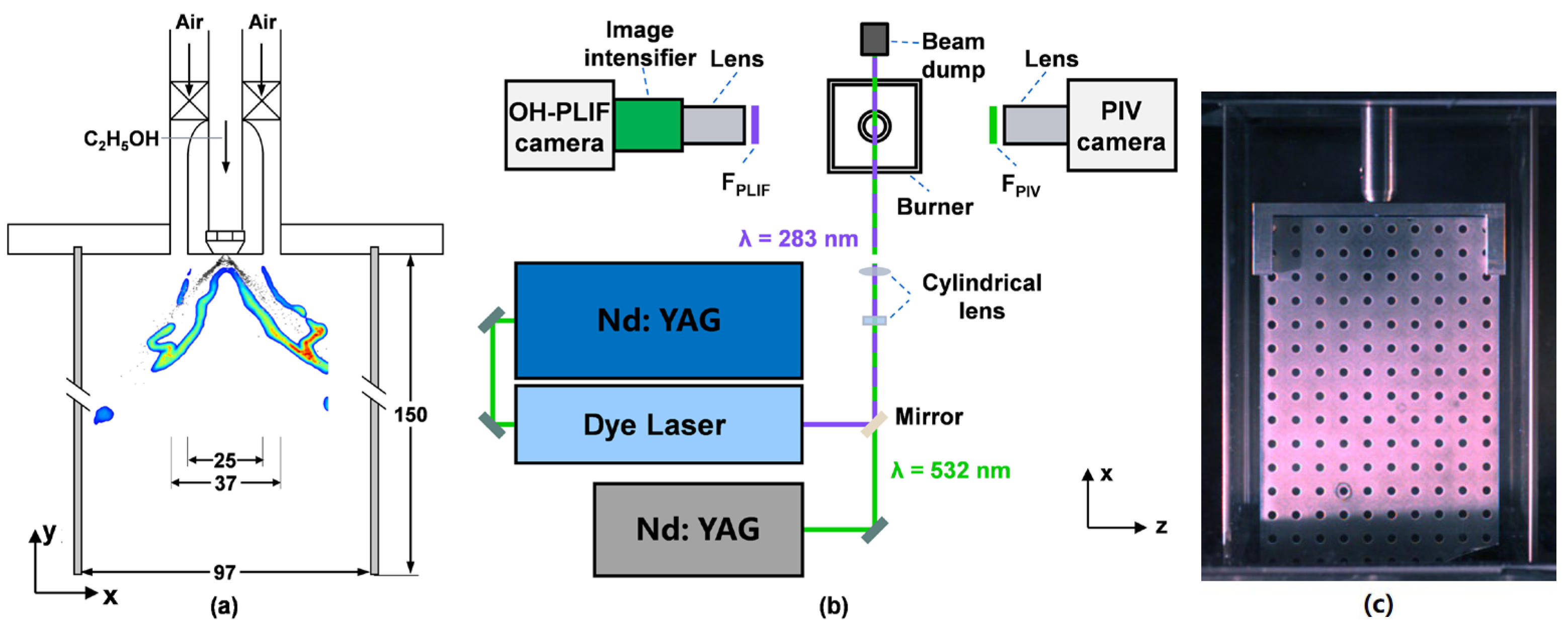
2.1. Combustor Facility

The spray swirling burner used in this work is shown in Figure 1a, and a central axisymmetric bluff body with a diameter of 25 mm, located in the center of the inflow passage, is surrounded by an annular path with an outer diameter of 37 mm. The air flowed through the annular path into a square combustion chamber with a 95 × 95 mm cross-section. The four sides of the combustion chamber were equipped with quartz glasses working as the optical access. The length and the height of every window were 95 mm and 150 mm, respectively, and the thickness of the quartz glass was 3 mm to allow as much signal to penetrate as possible. The swirler in the burner, produced via additive manufacturing, consists of 12 straight blades with a tilting angle of 45°. According to the method presented in Ref. [21], the calculated swirling number was about 0.74. The outlet surface of the nozzle (Danfoss: Nordborg, Denmark, 0.3 US gal/h) was flushed with the inlet of the combustion chamber; a pressure of 0.35 MPa with a fluctuation of 1% was applied to the nozzle, and the ethanol was injected into the combustion chamber, resulting in a solid spray cone with the angle of 60°.
The conditions of the test cases are listed in Table 1, and both non-reacting and reacting flows were conducted and compared for every case. An ethanol flow rate of 0.17 g/s was chosen in this work, and the corresponding blow-off limit Φ o v e r a l l of 0.11 was adopted, identical to the value reported in Ref. [22]. The air flow rate, controlled by a mass flow controller (Seven Star: Beijing, China, D07-60B series) with an accuracy of 2% and repeated precision of 0.2%, was gradually increased until the flame reached the blow-off, and the corresponding U B O was 20.6 m/s. The flow rate system was controlled using an in-house LabVIEW program to guarantee the reliability and reproducibility of the results. The Sauter mean diameter (SMD) of the majority of droplets from this Danfoss commercial nozzle is less than 60 µm, and the corresponding Stokes number of the majority of droplets was calculated to be ≪1 [23,24], making the spray droplets a good tracer for the flow field measurements in this work.

2.2. Laser Diagnostics

Due to the excellent evaporation characteristics of ethanol, the chamber and optical window are clean, which is beneficial for performing various laser diagnostic techniques [25,26,27]. The laser diagnostic system is demonstrated in Figure 1b. The x- and y-directions are the propagating directions of the laser and flow, respectively, and the z-direction is perpendicular to the laser sheet.
2D-PIV measurements were performed with a dual-cavity Nd:YAG laser (Beamtech: Beijing, China, Vlite-200), running at 10 Hz with an output wavelength of 532 nm, and the laser beam was shaped into a 125 mm-high laser sheet. A fixed time interval of 50 μs was configured between the twin pulses, and the energy of each pulse was approximately 8 mJ. A high-speed CMOS camera (Phantom: Wayne, NJ, USA, v2012), operating in dual-frame mode, was applied to record the PIV images perpendicular to the laser sheet. The recording frequency was set to 100 Hz, which is the minimum frame rate of the camera, and the shooting time was as long as 30 s. A 105 mm focal length UV lens (Sodern CERCO: Limeil-Brévannes, France, f/2.8) was used in the PIV configuration, and a bandpass filter (Edmund in Barrington, IL, USA, 65216) was adopted before the camera lens to reduce the interference of the flame chemiluminescence.
For OH-PLIF measurements, an Nd: YAG laser (Quantel: Lannion, France, Q-Smart 850), operating at 10 Hz with an output wavelength of 532 nm, was utilized to pump a dye laser (Sirah Lasertechnik: Grevenbroich, Germany, Cobra-Stretch) with the working medium of Rhodamine/ethanol solution. The fundamental wavelength of the dye laser was finely tuned to 566 nm via grating, and then a frequency doubling unit was adopted, resulting in the output wavelength of about 283 nm to excite the Q1(6) line in the A 1 Σ– X 2 Π ( v = 1 , v = 0 ) band of OH radicals in flames. The energy of the 283 nm laser was about 18 mJ/pulse, and the laser beam was shaped into a laser sheet with a height of 100 mm. An identical high-speed CMOS camera with an intensifier (Lambert: Groningen, The Netherlands, HiCATT 25) was placed perpendicular to the laser sheet to record the OH-PLIF image. The frame rate of the camera was set at 100 Hz, the gating time of the intensifier was set to 0.5 μs, and the recording time lasted for 30 s as well. The identical camera lens was equipped in front of the intensifier and fitted with a filter (Edmund: Barrington, IL, USA, 34980), centered at 310 nm with a passing band of 10 nm, and a notch filter centered at 532 nm with a blocking band of 17 nm, to reduce the stray light interference and to remove the Mie scattering of ethanol droplets.
Cameras and lasers were triggered using a programmable timing control unit (LaVision: Göttingen, Germany, PTU X) and a data acquisition board (PCIe 6363) for simultaneous PIV/PLIF measurements. The timing of every 283 nm laser pulse was positioned between the corresponding 532 nm laser pulse pairs, and the variation of the flame and flow fields within this short time delay was negligible. The images of 800 × 1280 pixels were calibrated using a dot-target calibrator shown in Figure 1c and performed using the commercial software DaVis 8.4 from LaVision. The spatial resolutions of 160.1 and 162.1 μm/pixel were achieved for OH-PLIF and Mie scattering, respectively. This trivial resolution difference between these two techniques will not become an error source in comparing the results.

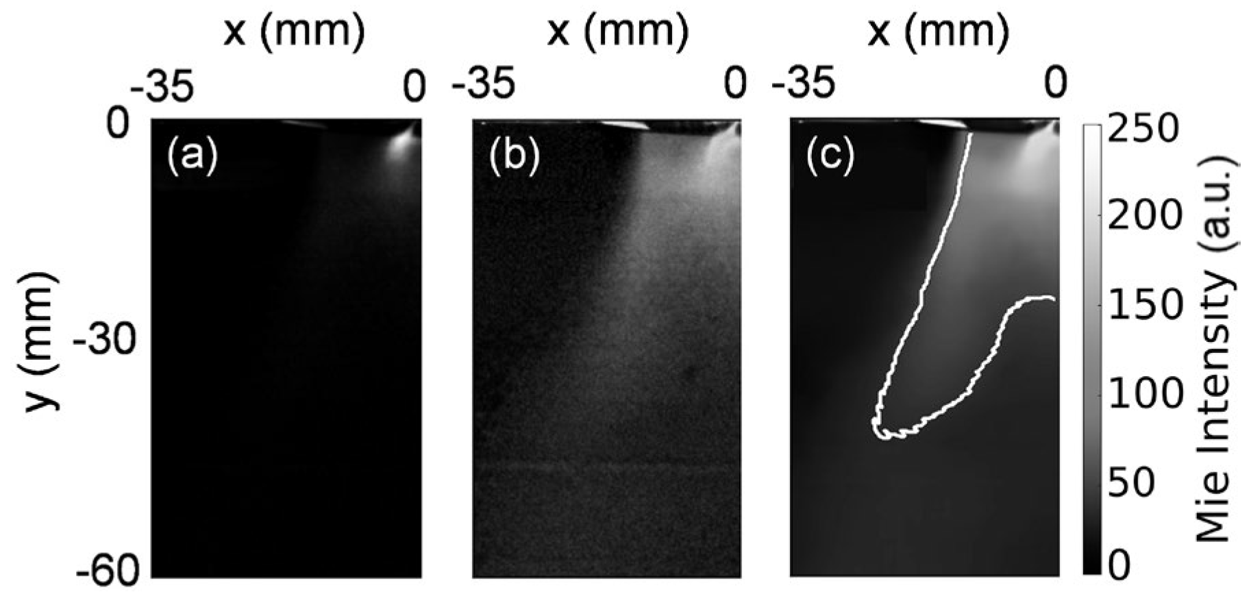
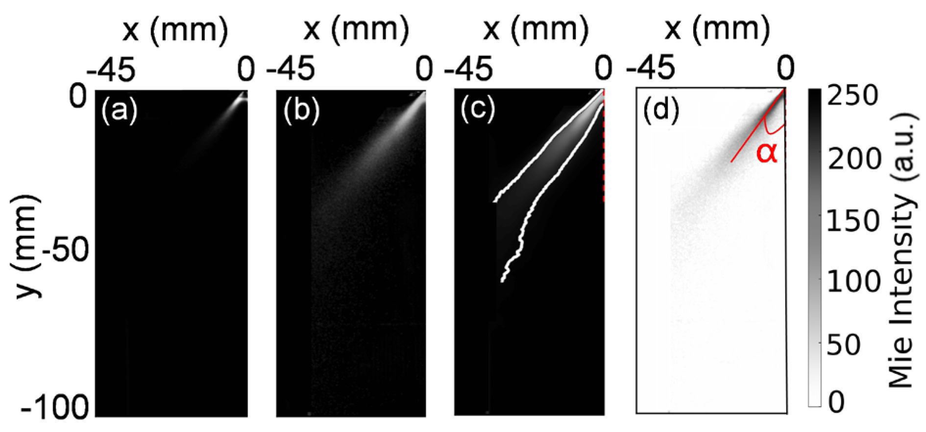
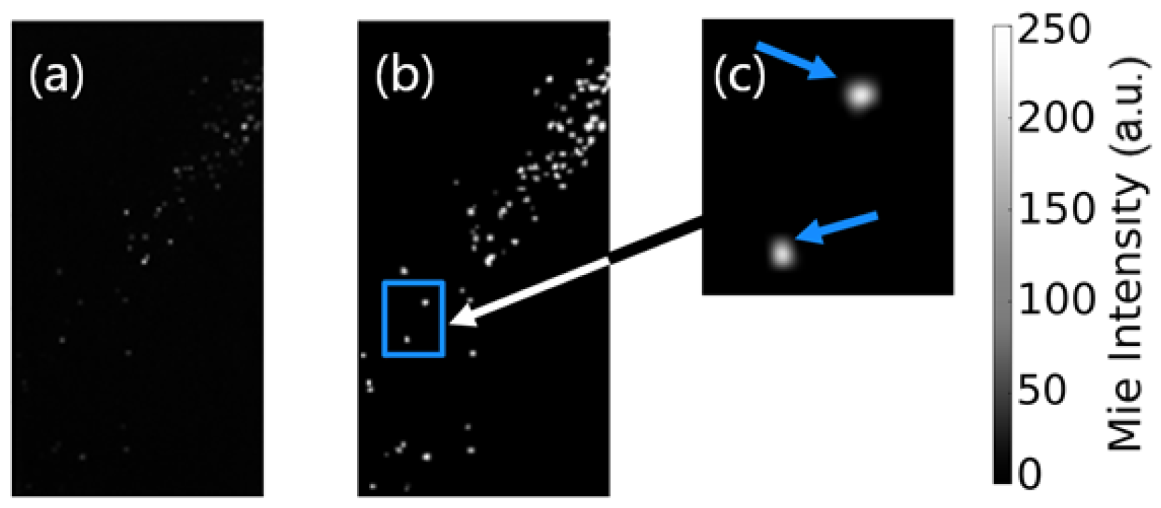
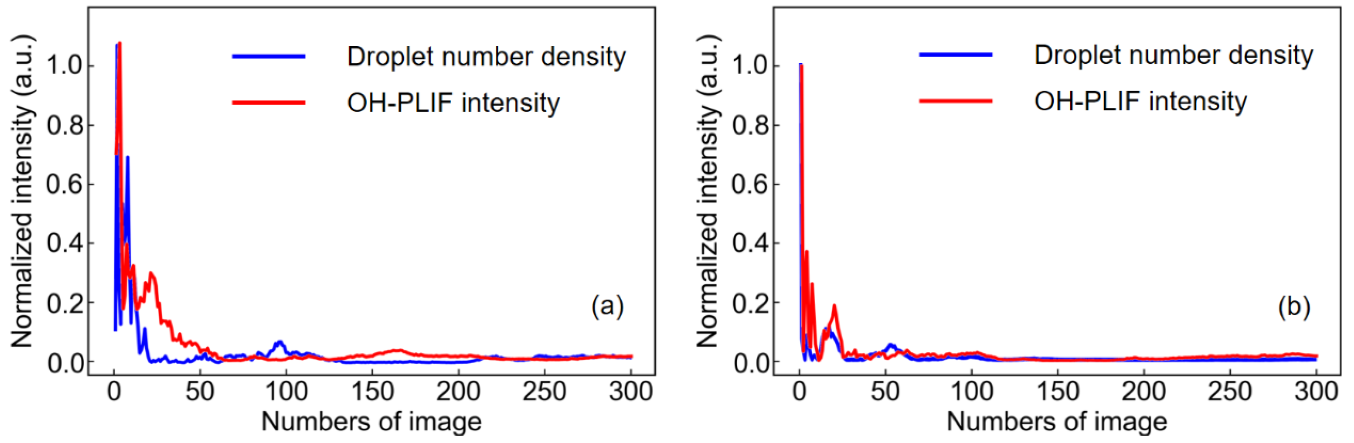
2.3. Image Processing

The LaVision DaVis 8.4 software was used for PIV image post-processing, the standard multiple iterative correlation algorithm was applied to obtain the velocity distribution, and the size of the iteration window was gradually reduced from 48 × 48 pixels (50% overlap) to 24 × 24 pixels (50% overlap), yielding a vector spacing of 0.5 mm. Finally, a 2D velocity field with a velocity uncertainty of about 0.12 m/s was obtained. Compared with the incoming air flow rate of 9.98 m/s, this uncertainty had trivial effects on evaluating the velocity field.
The characteristics of the spray distribution were analyzed based on the Mie scattering of ethanol droplets, and the gas phase cannot contribute to Mie scattering. Thus, it was easy to distinguish the liquid phase from the gas phase. It is necessary to process the raw Mie scattering images before analysis due to the vigorous background interference. Taking the image of Case 6 as an example, the image processing procedure for non-reacting and reacting sprays is explained step-by-step, as shown in Figure 2 and Figure 3, respectively. The region from the nozzle outlet (y = 0 mm) to the downstream position of y = 60 mm is selected, and only the left half of the image is displayed. First, 300 single-shot raw Mie scattering images were averaged, as illustrated in Figure 2a and Figure 3a, and the minimum background noise of 300 single-shot Mie scattering images was determined and subtracted from the averaged one. A convergence analysis based on different numbers of images had been conducted, and the results are displayed in Figure A1 in the Appendix A; a similar method can be found in Ref. [28]. It can be found that 300 samples are enough to achieve statistical significance. Next, the root mean square (RMS) image, as displayed in Figure 2b and Figure 3b, was obtained based on the 300 background-subtracted Mie scattering images to suppress the background interference. Then, the so-called non-local means filtering (NLM) [20] method was applied to the RMS image to smooth the image while preserving the sharpness of the solid edges, and the NLM-filtered images are shown in Figure 2c and Figure 3c. Finally, 15% of the maximum intensity of Figure 2c and Figure 3c was used as the threshold to define the spray profile, as demonstrated by the white curves in Figure 2c and Figure 3c. In the non-reacting spray flow, droplets are close to the nozzle outlet and the bluff body, leading to a broad, solid spray cone. The spray droplets are generally fine and fill the chamber, implying an excellent mixing between the droplets and air. In contrast, in the spray flame, a hollow spray cone is observed at the nozzle outlet due to the thermal expansion of the exhaust gas in RZ, and most of the spray droplets are involved in the chemical reaction. The spray brush thickness gradually increases downstream apart from the nozzle. The parameter of the spray half-angle, α , was defined between the line of the maximum Mie scattering intensity and the central symmetric axis of the nozzle [29], as shown in Figure 3d, which was the threshold-to-zero image of Figure 3c with a threshold of 15% of the maximum intensity.
Additionally, droplets can be recognized from the raw instantaneous Mie scattering images (Figure 4a), and 10% of the maximum intensity of the Mie scattering image was adopted as the threshold, and every connected domain was assumed and defined as a droplet, as shown in Figure 4b,c. Then, the droplet number density, nd, of every instantaneous Mie scattering image can be counted, and the mean droplet number density n d ¯   of 300 images can be calculated for different cases.
For 300 instantaneous OH-PLIF images in every test case, a binarization was applied to the raw images, and then the NLM filter and adaptive thresholding methods were performed. Morphological processing was utilized to erode the binarized image, resulting in a blur mask. Then, the mask was averaged, and the flame brush was obtained [30], which can be used to scientifically estimate the position of the reaction zone [31]. The value of the progress variable, <c>, represents the distribution probability of the reaction zone occurring at different locations, and the maximum value of <c> (<c>max) represents the highest probability of the occurrence of the reaction zone. In general, the larger the <c>max value, the more concentrated the reaction zone and the more stable the flame. Specifically, the <c> = 0.5 characterizes the flame shape. Taking Case 6 as an example, the flame brush distribution is shown in Figure 5, where only the left side of the image is displayed, and the <c> = 0.5 is represented by a black curve. The flame structure mainly consists of two branches, considering the symmetry of the flame. The inner and outer sides of each branch reside in the region closing to the nozzle outlet and the edge of the bluff body, respectively. The distance of its downstreammost position from the inlet surface of the combustion chamber was defined as the flame height, Lf, and its variation under different test conditions, which will be analyzed in the next session.
The symmetry factor of droplet number density, S n d , was calculated based on the ratio of n d ¯ on the left and right sides. Based on the flame brush obtained from OH-PLIF images, the value of <c> at every x-position was integrated along the y-direction and then averaged, and the x-position with the largest value of integrated <c> was obtained. Like the S n d , the symmetry factor of the reaction zone distribution, S < c > , was defined as the ratio of the corresponding x-position of the left and right sides of the flame brush. Generally, the closer to 1 for both S n d and S < c > , the more symmetric and stable the flame.
Moreover, the lift-off height, hlf, can be obtained based on OH-PLIF images, and it is a critical parameter for predicting blow-off events, as reported in previous studies [21]. The raw instantaneous OH-PLIF images were also processed utilizing a similar procedure of calculating the Lf, but the blur mask was applied to the NLM-filtered image as the last step of post-processing. The vertical distance between the inlet surface of the combustion chamber and the upstreammost point of the OH branch was defined as hlf. As shown in Figure 6, the image was divided into four divisions by the dashed lines, the one along x = 0 mm is the central symmetric axis of the burner, and the ones on the left and right are the lines passing through the nozzle outlet and the flame tips, thus the lift-off heights of the inner and outer side of the flame branches in every snapshot will be considered separately. The hlf calculated from divisions 1 and 4 were averaged and used to evaluate the lift-off height of the outer side of the flame branch, and correspondingly, the mean value of hlf from divisions 2 and 3 were utilized to analyze the lift-off characteristic of the inner side of the flame branch.

3. Results and Discussions

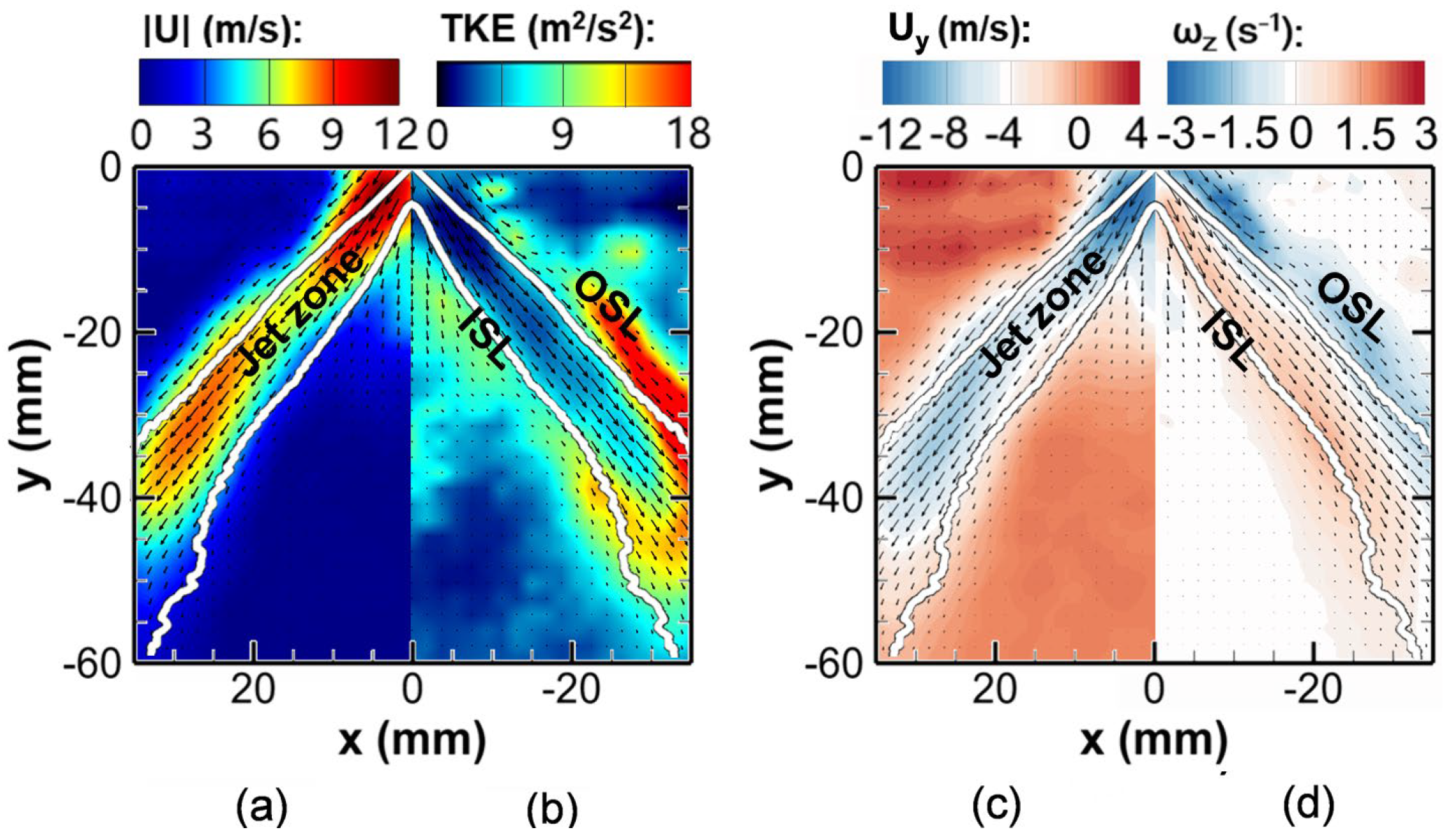
3.1. Non-Reacting Flow
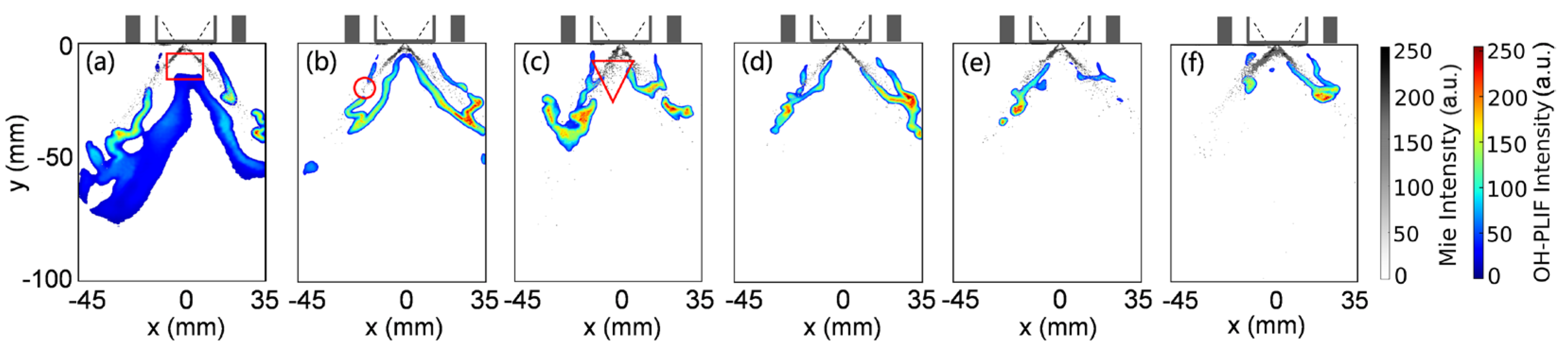
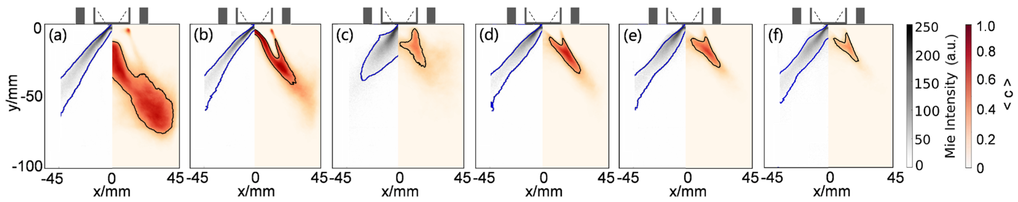
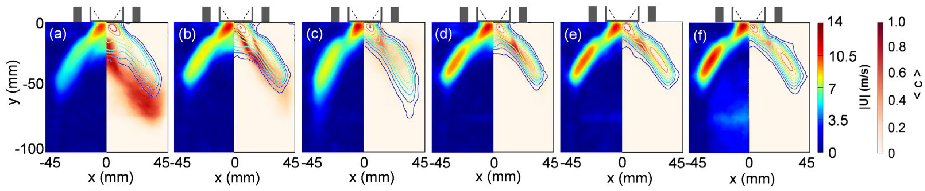
Several parameters are analyzed for the non-reacting flow, including velocity magnitude ( | U | ), turbulent kinetic energy ( T K E ), axil velocity ( U y ) , and vorticity ( ω z ) distribution, and the corresponding results are shown in Figure 7, still taking Case 6 as an example. The | U | was calculated as Equation (1). The component of vorticity along the z-direction ( ω z ) was computed using the curl of the velocity field based on the expression in Equation (2). The parameter of T K E reflects the magnitude of the turbulent velocity fluctuation. For the T K E calculation of 2D-PIV, it is assumed that the turbulence is isotropic, and the third component U z demonstrates a similar contribution to the turbulence as the amount from U x and U y . Accordingly, the formula for the calculation of T K E in this work was corrected and shown in Equation (3).
| U | = U x 2 + U y 2
ω z = U y x U x y
T K E = 3 4 [ U x U x ¯ 2 + U y U y ¯ 2 ]
As shown in Figure 7, all the calculations are based on the left side of the images, but for the convenience of demonstration, the results for T K E and ω z are flipped to the right side. The white curve in Figure 7 denotes the spray profile obtained based on the Mie scattering images. A high-speed annular jet is generated after the air enters the combustion chamber, the IRZ and ORZ are induced, and the ISL and outer shear layer (OSL) are observed in between. Comparing Figure 7a,b, the high Mie scattering intensity is mainly concentrated in the high-speed annular jet region, where the spray droplets are entrained by the swirling air directly to the lateral quartz window and then move downstream. As displayed in Figure 7c,d, the inner boundary of the spray cone roughly overlaps with the IRZ boundary, while the outer boundary is mainly located in the space between ISL and OSL. The fluctuations of turbulent velocity and vorticity along the z-direction in the ISL and OSL are significantly conducive to a rapid mixing between air and ethanol vapor.
For six different air flow rates, the distribution of the axial velocity U y along the central symmetric axis of x = 0 mm and the downstream position of y = −40 mm are plotted in Figure 8a and Figure 8b, respectively. The gray dashed line indicates U y = 0 m/s. It can be seen from Figure 8a that U y close to the nozzle outlet in the y < −10 mm range shows little deviation between different inlet air flow rates, and the trivial difference is induced via the actual droplet velocity fluctuation, which is mainly influenced by the injection pressure of ethanol. The effect of the air flow rate on U y is gradually apparent when the downstream distance increases. At the same time, when the air flow rate increases, the IRZ boundary expands upstream, and the magnitude of U y within the IRZ steadily magnifies. At the downstream position of y = −40 mm, as shown in Figure 8b, U y is relatively uniform along the radial direction at a low air flow rate, such as in Case 1. However, for larger air flow rates, the magnitude of U y in the high-speed annular jet zone and IRZ gradually increases, and the radial position of the profile of U y = 0 moves gently away from the central symmetric axis, indicating that the width of the IRZ also rises.

3.2. Reacting Flow

The flow field analysis of reacting spray flames, including velocity magnitude ( | U | ), T K E distribution, axil velocity ( U y ) , and vorticity ( ω z ) distribution is shown in Figure 9, which is evaluated for Case 6 as well, and the white curve is the corresponding spray profile. It can be seen in Figure 9a,c that there is a high-velocity jet region in the spray field, and a large velocity gradient of the droplet velocity exists between the nozzle outlet and the downstream jet. As illustrated in Figure 9b,d, turbulent velocity fluctuations and high vorticity are mainly concentrated in the low-velocity region outside the jet, and the spray profile roughly overlaps with the boundary of ISL and OSL. Combining the fuel droplet distribution, the mixing of the fuel/air mixture and exhaust gas will be enhanced by the high turbulence close to ISL and OSL.
The instantaneous examples obtained using the Mie scattering and OH-PLIF methods are superimposed in Figure 10, in which six typical cases with representative structures are chosen and compared, including stable to near-blow-off cases. It can be seen in Figure 10 that the Mie scattering of the spray is more robust in the region close to the nozzle outlet, and a dense droplet cloud is observed locally. The Mie scattering intensity in the IRZ is weak due to the hot exhaust recirculation in the IRZ, and the spray shows a hollow cone structure for all six test cases. Most droplets are entrained by the swirling air and transported downstream, the evaporation is enhanced, the droplet cloud density is significantly reduced, the droplet distribution becomes sparser, and the heat and mass transfer between the droplets and the surrounding air rises, which will, in turn, help the evaporation. In addition, the distribution of droplet size in reacting and non-reacting conditions is similar in the vicinity of the nozzle outlet, which is determined by the characteristic of the nozzle, and this assessment is also demonstrated in Ref. [32], indicating that the droplet size has limited feedback to the flame. Compared with the non-reacting cases, an apparent decrease in the droplet size is observed at downstream locations in reactive conditions, where a high level of temperature and turbulent kinetic energy promotes the evaporation of droplets and enhances mixing between air and tiny droplets, which is beneficial to the stability of the spray flame.
Regarding the flame structure, two flame branches are observed for all the cases in Figure 10, and each branch consists of inner and outer sides. In Figure 10a, the air entrainment in the IRZ close to the nozzle is relatively weak, and the droplet cloud absorbs heat from the hot exhaust gas. Thus, a considerable distance between the root of the inner side of the flame branch and the nozzle outlet is observed, marked using a red box in Figure 10a, where is presumed to be filled with the mixture of ethanol vapor and pyrolysis products [27]. Additionally, a broadly distributed OH-PLIF is observed in the IRZ since the spray droplets in the inner side of the flame branch are not entirely consumed and will continue to react in the IRZ, showing behaviors like a premixed flame. Figure 10b exhibits an M-shaped flame, a typical stable flame structure in the swirling bluff body burner, and the inner and outer sides of the two flame branches are anchored at the nozzle outlet and the edge of the bluff body, respectively, which is also observed in [33]. The continuous OH-PLIF distribution, like the characteristic of a non-premixed flame, encloses the droplet distribution. Almost no OH-PLIF can be observed in the IRZ, indicating that the fuel droplets are entirely exhausted in the flame branches. The outer flame front is occasionally broken up, as noticed in the red circle in Figure 10b, and OH fragments appear. For a higher air flow rate, as shown in Figure 10c, the root of the inner sides of two flame branches fail to stabilize at the nozzle outlet and lift off, which is emphasized by the red triangle. The flame height decreases when the air flow rate increases further, as shown in Figure 10d,e. Compared to the inner side of the flame branch, the root of the outer side cannot continuously stabilize at the bluff body edge but lifts randomly, and many droplets pass through the outer side of the flame branch. In the case close to the blow-off, it can be seen in Figure 10f that the flame height further decreases, and the flame is largely quenched and literally very asymmetric, indicating an unstable status.
The averaged droplet distribution and its corresponding flame structure of Cases 1, 3, 5, 7, 10, and 12 are further investigated, as shown in Figure 11a–f, respectively. For every case, the averaged Mie scattering image is displayed on the left side and superimposed by the spray profile (denoted by the blue solid line). The flame brush extracted from the OH-PLIF images is shown on the right side and overlaid by the <c> = 0.5 curve (marked by the black solid line). All the images are processed in the left half, and the flame brush is flipped to the right side for comparison.
In the spray swirling flame with a low air flow rate, as shown in Figure 11a, the flame is not anchored to the bluff body, and the outer flame side is lifted [34], and the flame is named according to this. When the air flow rate increases, as displayed in Figure 11b, the spray structure is like that in Figure 11a, but the flame brush is reduced in both thickness and length, showing a stable M shape and the inner and outer side of the flame branch is anchored to the nozzle outlet and the edge of the bluff body. In the left half of Figure 11c, the length of the spray cone and the spray half-angle decrease, the droplet number density increases, the distribution of the fuel droplets is more expansive, and the appearance of droplets in IRZ can be found. Moreover, in the right half of Figure 11c, the flame length is short, the <c>max is low, and the flame brush shrinks close to the bluff body. Compared with the other cases shown in Figure 11, the nonlinear behavior in spray and flame in Figure 11c is due to the intrinsic thermoacoustic instability around 100 Hz in Case 5. When further increasing the air flow rate to the near-blow-off condition (Case 12), Figure 11d–f, the width of the spray cone of Figure 11f keeps expanding, the flame brush length reduces, and the value of <c>max in Figure 11f is only about 0.5 times that of Figure 11b. Large droplets have not reacted yet and pass through the flame area when approaching the blow-off, aggravating the combustion instability. It can be seen that the evolution of the outer flame angle follows the behavior of the spray cone half-angle in the M-shaped flame as the swirling air flow rate increases. In contrast, the inner flame angle keeps increasing until it blows off [35].
Figure 12 displays the change of the spray half-angle α (denoted in red) and the flame height Lf (marked in black) to better understand the droplet distribution and flame characteristics for different air flow rates. Generally, the α and the Lf are expected to decrease gradually as the air flow rate increases. It is observed that the reduction of combustion intensity and flame luminescence is significant. However, nonlinear behavior occurs at the flow rate of 7.13, 8.56, and 9.98 m/s, corresponding to Cases 4, 5, and 6, since flame instability was observed in these cases, exhibiting strong flow pulsation and combustion noise, accompanied by the apparent fluctuation of spray distribution. When the air flow rate keeps rising to 12 m/s, the thermoacoustic instability weakens, and recirculation intensity increases gradually, leading to an increment of α and Lf.

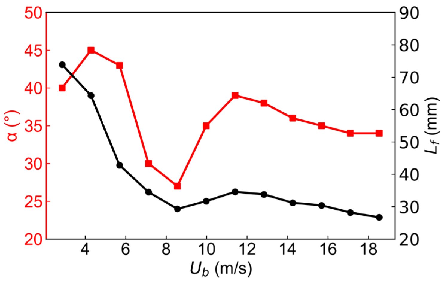
3.3. Flame Symmetry and Stability

The averaged velocity fields and flame brushes of the spray swirling flame at varying cases mentioned above are analyzed and compared in Figure 13, which shows the expected general stability of the spray flames. The spray velocity fields of different test cases are shown on the left side, and the iso-contour profiles of the velocity overlaid against the flame brush are displayed on the right side. Figure 13a shows that the spray velocity field mainly coincides with the high-speed air jet ring, where the mixing of the fresh air and fuel vapor is enhanced, which is helpful to the consequent chemical reactions [11,36]. The reaction zone is dominantly distributed in the IRZ; thus, the stability of the inner side of the flame branch close to the nozzle outlet is better. In contrast, the droplet velocity near the edge of the bluff body is more significant; hence, the local stability of the outer side of the flame branch is worse compared to the inner one. In Figure 13b, the reaction zone is mainly distributed in the low-velocity shear layer region between the spray jet, IRZ, and ORZ, and the flame stability is similar to that of Figure 13a. When the air flow rate increases further, as shown in Figure 13c–e, the droplet velocity gradient is more and more apparent between the nozzle outlet and the downstream area, accompanying the higher T K E in the ISL and OSL at the periphery of the spray cone. Continuing increasing the air flow rate until the blow-off, the intense local strain rate of the ISL and OSL enhances the interaction between the air jet ring and the spray significantly, it can be seen from Figure 13f that the droplet velocity increases further in the area overlapping with the reaction zone, which is not conducive to flame stability closing to the nozzle outlet or bluff body edge.
Figure 14 plots the variation of mean droplet number density n d ¯ (red) and <c>max (black) at different air flow rates to quantitatively evaluate the flame stability, where n d ¯ is the number of droplets remaining that are not involved in the chemical reaction. The combustion of droplets is insufficient when n d ¯ is more considerable. As displayed in Figure 14, these two parameters exhibit nonlinear behavior with opposite trends. When the air flow rate increases from 2.86 (Case 1) to 4.28 m/s (Case 2), the gasification of the droplets is enhanced, the droplet number density decreases, and the flame tends to be more stable at this stage. As mentioned above, the nonlinear behavior is related to the strong thermoacoustic instability in Cases 4 and 5, with the highest n d ¯ and dispersed reaction zone. When the air flow rate further increases until blow-off, the heat convective/radiative transfer is weakened, and evaporation of droplets will become poor, the droplet number density increases, the combustion efficiency decreases, <c>max decreases gradually, and the dramatic deterioration of flame stability is reached.
Similarly, a flame symmetry-based method [37] was chosen to provide an unambiguous scientific correlation with flame stability. Figure 15 depicts the variation of symmetry factor S n d (red) and S < c > (black) as a function of air flow rate, and the two quantities demonstrate a gentle decrease when increasing the air flow rate, identifying that the flame symmetry is getting worse and the flame stability is steadily weakening, which is also observed in [33]. It is mainly related to the intense interaction between droplets and flame, including the high fluctuation of droplet density, flame quenching, and random lift-off. The nonlinear behavior of S n d is also related to the strong thermoacoustic instability in Case 5.
Furthermore, the flame stability can be evaluated using the statistical analysis of the lift-off height reported in previous studies [21,38,39]. The mean lift-off heights obtained from the six typical cases are plotted in Figure 16, and the solid red and black lines represent the results for the inner and outer sides of the flame branches, respectively. At a low air flow rate, for example, in Case 1, the lift-off heights of the inner and outer flame branches are significant due to the mixing of droplets, vapors, and pyrolysis products close to the nozzle outlet. In Case 3, the lift-off height of the inner branch achieves a minor value because the flame is firmly attached to the nozzle outlet. At the same time, the lift-off height of the outer branch is larger than the inner one due to the droplets passing through the outer side of the flame branch, which is similar to the findings in Ref. [40]. As the air flow rate increases until Case 12, the flame lifts off in the vicinity of the bluff body randomly, the flame asymmetry is apparent gradually, and the lift-off height of the inner and outer sides of the flame branches first increases and then decreases slowly. In addition, the lift-off height of the inner branch of the flame is slightly higher than the outer branch in conditions with high air flow rates, opposite to that at low air flow rates. This is supposed to be related to the enhanced IRZ and ORZ, but the influence of the rising velocity is not equal, and the effect in the IRZ is more significant, indicating a worse stabilization of the inner side of the flame branch in near-blow-off (Case 12) flames. Furthermore, as explained in Refs. [41,42], the formation and development of the flame will consume larger amount high-temperature combustion products in the IRZ, resulting in a higher flame lift-off height.

4. Conclusions

Experimental studies of ethanol spray swirling flames in an axial bluff -body stabilized combustor were conducted using simultaneous measurements of PIV and OH-PLIF running at 10 Hz. Six cases (with typical characteristics of outer-side-flame-lifting, stable, and near-blow-off cases, respectively) were tested and compared, and the results show that the flame structure and stability were strongly correlated with the distribution of fuel droplets. The T K E and vorticity ( ω z ) fields highlight that the existence of ISL and OSL are significantly conducive to rapidly mixing air and ethanol vapor. In the outer-side-flame-lifting flames, a broadly distributed OH-PLIF is observed in the IRZ, and a similar characteristic in the premixed flame is noticed, since the spray droplets are not entirely consumed and will continue to react in the IRZ. The stable flames demonstrate a typical M-shaped structure, anchoring close to the nozzle outlet and the edge of the bluff body. In the near-blow-off cases, the inner and outer branches lift off randomly, an expanded spray cone passes through the flame area, and the flame is very unstable. Furthermore, as the air flow rate increased, the local strain rate of the ISL and OSL rises, and the interaction between the air jet ring and the spray is further enhanced, resulting in a velocity gradient between the nozzle outlet and downstream, which is not conducive to local flame stability. As shown in the symmetry factor of droplet number density S n d and reaction zone distribution S < c > , the flame symmetry keeps worsening as the air flow rate increases, which is mainly related to the intense interaction between droplets and flame, and the flame is prone to be unstable. Based on the lift-off height, it can be found that the inner side of the flame branch exhibits a worse stabilization than the outer one when approaching the blow-off. To reveal the coupling mechanism of turbulence-droplet-flame on flame stability in our future work, the simultaneous measurements of the droplet number density, air flow field, and critical radical distribution (such as OH and CH2O-PLIF, etc.) will be carried out in the same ethanol spray swirling flames.

Author Contributions

Conceptualization, M.W.; methodology, M.W. and Y.G.; software, M.W. and X.W.; validation, M.W. and C.F.; formal analysis, M.W., C.F., X.W., K.L. and Y.G.; investigation, M.W., C.F. and K.L.; resources, S.M., M.Z., X.X. and Y.G.; data curation, Y.G.; writing—original draft preparation, M.W.; writing—review and editing, C.F., S.M., M.Z. and Y.G.; visualization, M.W. and X.W.; supervision, J.Y. and Y.G.; project administration, Y.G.; funding acquisition, Y.G. All authors have read and agreed to the published version of the manuscript.

Funding

This research was funded by the National Natural Science Foundation of China (Grant No. U2141221, 52076136), Natural Science Foundation of Shanghai (Grant No. 22ZR1467900), the National Science and Technology Major Project (Grant No. J2019-III-0004-0047, HT-Y2022-III-0001-0010), and the Center for Basic Science of Aero Engines and Gas Turbines Project of China (Grant No. P2022-B-II-019-001).

Data Availability Statement

The data presented in this study are available on request from the corresponding author ([email protected]).

Conflicts of Interest

The authors declare that they have no known competing financial interests or personal relationships that could have appeared to influence the work reported in this paper.

Appendix A

The accumulated variance, ( s i , j s i , 300 ) 2 , of droplet number density and OH-PLIF intensity for Cases 3 and 12 are shown in Figure A1. Here, i = 1 and 2 , related to the droplet number density and OH-PLIF intensity respectively, s is the mean of the corresponding parameter based on j images ( j 300 ), and the statistical significance has already been achieved utilizing 300 images.
Figure A1. The convergence analysis as a function of image number for (a) Case 3 and (b) Case 12.
Symmetry 16 00205 g0a1

References

  1. Moeck, J.P.; Bourgouin, J.-F.; Durox, D.; Schuller, T.; Candel, S. Nonlinear interaction between a precessing vortex core and acoustic oscillations in a turbulent swirling flame. Combust. Flame 2012, 159, 2650–2668. [Google Scholar] [CrossRef]
  2. Huang, R.F.; Yen, S.C. Aerodynamic characteristics and thermal structure of nonpremixed reacting swirling wakes at low Reynolds numbers. Combust. Flame 2008, 155, 539–556. [Google Scholar] [CrossRef]
  3. Syred, N.; Beér, J.M. Combustion in swirling flows: A review. Combust. Flame 1974, 23, 143–201. [Google Scholar] [CrossRef]
  4. Presser, C.; Gupta, A.K.; Semerjian, H.G.; Avedisian, C.T. Droplet transport in a swirl-stabilized spray flame. J. Propuls. Power 1994, 10, 631–638. [Google Scholar] [CrossRef]
  5. Chatterjee, S. Turbulent Non-Premixed Swirl-Stabilized Flames of Gaseous and Liquid Fuels in a Gas Turbine Model Combustor. Ph.D. Thesis, University of Toronto, Toronto, ON, Canada, 2018. [Google Scholar]
  6. Foust, M.; Thomsen, D.; Stickles, R.; Cooper, C.; Dodds, W. Development of the GE Aviation Low Emissions TAPS Combustor for Next Generation Aircraft Engines. In Proceedings of the 50th AIAA Aerospace Sciences Meeting Including the New Horizons Forum and Aerospace Exposition, Nashville, TN, USA, 9–12 January 2012. [Google Scholar]
  7. Dhanuka, S.K.; Temme, J.E.; Driscoll, J.F. Lean-limit combustion instabilities of a lean premixed prevaporized gas turbine combustor. Proc. Combust. Inst. 2011, 33, 2961–2966. [Google Scholar] [CrossRef]
  8. García-Oliver, J.M.; Malbec, L.-M.; Toda, H.B.; Bruneaux, G. A study on the interaction between local flow and flame structure for mixing-controlled Diesel sprays. Combust. Flame 2017, 179, 157–171. [Google Scholar] [CrossRef]
  9. Zhang, R.; Pratt, A.C.; Lucht, R.P.; Slabaugh, C.D. Structure conditioned velocity statistics in a high pressure swirl flame. Proc. Combust. Inst. 2019, 37, 5031–5038. [Google Scholar] [CrossRef]
  10. Li, L.a.; Li, X.; Wang, Z.; Wang, B.; Lin, H.; Hu, W.; Chang, F.; Zhou, B. Experimental investigation of the flow-spray field in a realistic concentric staged high-temperature-rise combustor. Fuel 2022, 318, 123606. [Google Scholar] [CrossRef]
  11. Slabaugh, C.D.; Pratt, A.C.; Lucht, R.P. Simultaneous 5 kHz OH-PLIF/PIV for the study of turbulent combustion at engine conditions. Appl. Phys. B 2014, 118, 109–130. [Google Scholar] [CrossRef]
  12. Bae, C.; Kim, J. Alternative fuels for internal combustion engines. Proc. Combust. Inst. 2017, 36, 3389–3413. [Google Scholar] [CrossRef]
  13. Masri, A.R.; Gounder, J.D. Turbulent Spray Flames of Acetone and Ethanol Approaching Extinction. Combust. Sci. Technol. 2010, 182, 702–715. [Google Scholar] [CrossRef]
  14. Gounder, J.D.; Kourmatzis, A.; Masri, A.R. Turbulent piloted dilute spray flames: Flow fields and droplet dynamics. Combust. Flame 2012, 159, 3372–3397. [Google Scholar] [CrossRef]
  15. Mansour, M.S.; Alkhesho, I.; Chung, S.H. Stabilization and structure of n-heptane flame on CWJ-spray burner with kHZ SPIV and OH-PLIF. Exp. Therm. Fluid Sci. 2016, 73, 18–26. [Google Scholar] [CrossRef]
  16. Edalati-nejad, A.; Fanaee, S.A.; Khadem, J. The unsteady investigation of methane-air premixed counterflow flame into newly proposed plus-shaped channel over palladium catalyst. Energy 2019, 186, 115833. [Google Scholar] [CrossRef]
  17. Edalati-nejad, A.; Fanaee, S.A.; Ghodrat, M.; Khadem, J. Investigation of Unsteady Premixed Micro/Macro Counterflow Flames for Lean to Rich Methane/Air Mixture. J. Energy Resour. Technol. 2021, 143, 052302. [Google Scholar] [CrossRef]
  18. Malbois, P.; Salaün, E.; Vandel, A.; Godard, G.; Cabot, G.; Renou, B.; Boukhalfa, A.M.; Grisch, F. Experimental investigation of aerodynamics and structure of a swirl-stabilized kerosene spray flame with laser diagnostics. Combust. Flame 2019, 205, 109–122. [Google Scholar] [CrossRef]
  19. Renaud, A.; Ducruix, S.; Scouflaire, P.; Zimmer, L. Flame shape transition in a swirl stabilised liquid fueled burner. Proc. Combust. Inst. 2015, 35, 3365–3372. [Google Scholar] [CrossRef]
  20. Renaud, A.; Ducruix, S.; Zimmer, L. Bistable behaviour and thermo-acoustic instability triggering in a gas turbine model combustor. Proc. Combust. Inst. 2017, 36, 3899–3906. [Google Scholar] [CrossRef]
  21. Cavaliere, D.E.; Kariuki, J.; Mastorakos, E. A Comparison of the Blow-Off Behaviour of Swirl-Stabilized Premixed, Non-Premixed and Spray Flames. Flow Turbul. Combust. 2013, 91, 347–372. [Google Scholar] [CrossRef]
  22. Letty, C.; Mastorakos, E.; Masri, A.R.; Juddoo, M.; O’Loughlin, W. Structure of igniting ethanol and n-heptane spray flames with and without swirl. Exp. Therm. Fluid Sci. 2012, 43, 47–54. [Google Scholar] [CrossRef]
  23. Ahmed, S.A. Three component velocity measurements of an isothermal confined swirling flow. Proc. Inst. Mech. Eng. 1997, 211, 175–185. [Google Scholar] [CrossRef]
  24. Liu, C.; Liu, F.; Yang, J.; Mu, Y.; Hu, C.; Xu, G. Experimental Investigation of Spray and Combustion Performances of a Fuel-Staged Low Emission Combustor: Effects of Main Swirl Angle. J. Eng. Gas Turbines Power 2017, 139, 121502. [Google Scholar] [CrossRef]
  25. Renaud, M.A. High-Speed Diagnostics for the Study of Flame Stabilization and Transient Behaviour in a Swirled Burner with Variable Liquid-Fuel Distribution. Ph.D. Thesis, Paris-Saclay University, Paris, France, 2015. [Google Scholar]
  26. An, Q.; Kheirkhah, S.; Bergthorson, J.; Yun, S.; Hwang, J.; Lee, W.J.; Kim, M.K.; Cho, J.H.; Kim, H.S.; Vena, P. Flame stabilization mechanisms and shape transitions in a 3D printed, hydrogen enriched, methane/air low-swirl burner. Int. J. Hydrogen Energy 2021, 46, 14764–14779. [Google Scholar] [CrossRef]
  27. Sidey, J.; Mastorakos, E. Visualisation of turbulent swirling dual-fuel flames. Proc. Combust. Inst. 2017, 36, 1721–1727. [Google Scholar] [CrossRef]
  28. Wang, X.; Liu, K.; Fu, C.; Wang, M.; Yu, J.; Yan, Y.; Li, J.; Ge, X.; Gao, Y. Investigation of the influence of the bluff-body temperature on a lean premixed DME/air flame approaching blowoff. Exp. Therm. Fluid Sci. 2024, 152, 111123. [Google Scholar] [CrossRef]
  29. Fan, X.; Liu, C.; Xu, G.; Zhang, C.; Wang, J.; Lin, Y. Experimental investigations of the spray structure and interactions between sectors of a double-swirl low-emission combustor. Chin. J. Aeronaut. 2020, 33, 589–597. [Google Scholar] [CrossRef]
  30. Malbois, P.; Salaün, E.; Rossow, B.; Cabot, G.; Bouheraoua, L.; Richard, S.; Renou, B.; Grisch, F. Quantitative measurements of fuel distribution and flame structure in a lean-premixed aero-engine injection system by kerosene/OH-PLIF measurements under high-pressure conditions. Proc. Combust. Inst. 2019, 37, 5215–5222. [Google Scholar] [CrossRef]
  31. Roy Chowdhury, B.; Cetegen, B.M. Effects of fuel properties and free stream turbulence on characteristics of bluff-body stabilized flames. Combust. Flame 2018, 194, 206–222. [Google Scholar] [CrossRef]
  32. Verdier, A.; Marrero Santiago, J.; Vandel, A.; Saengkaew, S.; Cabot, G.; Grehan, G.; Renou, B. Experimental study of local flame structures and fuel droplet properties of a spray jet flame. Proc. Combust. Inst. 2017, 36, 2595–2602. [Google Scholar] [CrossRef]
  33. Yuan, R.; Kariuki, J.; Mastorakos, E. Measurements in swirling spray flames at blow-off. Int. J. Spray Combust. Dyn. 2018, 10, 185–210. [Google Scholar] [CrossRef]
  34. Santhosh, R.; Basu, S. Transitions and blowoff of unconfined non-premixed swirling flame. Combust. Flame 2016, 164, 35–52. [Google Scholar] [CrossRef]
  35. Yuan, R. Measurement in Swirl-Stabilised Spray Flames at Blow-Off. Ph.D. Thesis, University of Cambridge, Cambridge, UK, 2015. [Google Scholar]
  36. Chterev, I.; Rock, N.; Ek, H.; Emerson, B.; Seitzman, J.; Jiang, N.; Roy, S.; Lee, T.; Gord, J.; Lieuwen, T. Simultaneous imaging of fuel, OH, and three component velocity fields in high pressure, liquid fueled, swirl stabilized flames at 5 kHz. Combust. Flame 2017, 186, 150–165. [Google Scholar] [CrossRef]
  37. Dejoan, A.; Jiménez, C.; Martínez-Ruiz, D.; Muntean, V.; Sánchez-Sanz, M.; Kurdyumov, V.N. Flame propagation in narrow horizontal channels: Impact of the gravity field on the flame shape. Proc. Combust. Inst. 2023, 39, 1535–1543. [Google Scholar] [CrossRef]
  38. Giusti, A.; Mastorakos, E. Detailed chemistry LES/CMC simulation of a swirling ethanol spray flame approaching blow-off. Proc. Combust. Inst. 2017, 36, 2625–2632. [Google Scholar] [CrossRef]
  39. Giusti, A.; Kotzagianni, M.; Mastorakos, E. LES/CMC Simulations of Swirl-Stabilised Ethanol Spray Flames Approaching Blow-Off. Flow Turbul. Combust. 2016, 97, 1165–1184. [Google Scholar] [CrossRef]
  40. Sidey, J.A.M.; Mastorakos, E. Stabilisation of swirling dual-fuel flames. Exp. Therm. Fluid Sci. 2018, 95, 65–72. [Google Scholar] [CrossRef]
  41. Shang, W.; He, Z.; Wang, Q.; Cao, J.; Li, B.; Leng, X.; Tamilselvan, P.; Li, D. Experimental and analytical study on capture spray liquid penetration and combustion characteristics simultaneously with Hydrogenated Catalytic Biodiesel/Diesel blended fuel. Appl. Energy 2018, 226, 947–956. [Google Scholar] [CrossRef]
  42. Li, D.; He, Z.; Xuan, T.; Zhong, W.; Cao, J.; Wang, Q.; Wang, P. Simultaneous capture of liquid length of spray and flame lift-off length for second-generation biodiesel/diesel blended fuel in a constant volume combustion chamber. Fuel 2017, 189, 260–269. [Google Scholar] [CrossRef]
Figure 1. (a) Schematics of the swirled burner with a central axisymmetric bluff body, (b) optical system, and (c) the 2D calibrator.
Symmetry 16 00205 g001
Figure 2. Post-processing procedure of spray Mie scattering image in non-reacting cases based on 300 single-shots, including (a) averaged, (b) RMS, and (c) NLM-filtered image (white curve represents the spray profile).
Symmetry 16 00205 g002
Figure 3. Post-processing procedure of spray Mie scattering image in reacting cases based on 300 single-shots, including (a) averaged, (b) RMS, (c) NLM-filtered (white curves represent spray profiles), and (d) threshold-to-zero image (red line is used to label the spray half-angle α).
Symmetry 16 00205 g003
Figure 4. Post-processing procedure of droplet number density based on spray Mie scattering image, including (a) raw image, (b) thresholding image, and (c) inset image with droplet location identification.
Symmetry 16 00205 g004
Figure 5. The flame brush and the flame height Lf (black curve represents the profile of <c> = 0.5) obtained based on OH-PLIF images.
Symmetry 16 00205 g005
Figure 6. The lift-off height hlf of the inner and outer sides of two flame branches (the lift-off height of the outer side is marked by red color, and the value of the inner side is denoted by green color).
Symmetry 16 00205 g006
Figure 7. The averaged flow field structure calculated from Mie scattering images of non-reacting spray (Case 6), (a) magnitude of velocity U y , (b) T K E , (c) axial velocity U y , and (d) vorticity along the z-direction ω z (white curves represent spray profiles).
Symmetry 16 00205 g007
Figure 8. Axial velocity U y distribution along (a) the central symmetric axis of x = 0 mm with varying y-position and (b) the downstream location of y = −40 mm with varying x-position.
Symmetry 16 00205 g008
Figure 9. The averaged flow field structure calculated from Mie scattering images of reacting spray flame (Case 6), (a) magnitude of velocity U y , (b) T K E , (c) axial velocity U y , and (d) vorticity along the z-direction (white curves represent the spray profile).
Symmetry 16 00205 g009
Figure 10. The overlaid instantaneous Mie scattering and OH-PLIF images obtained simultaneously for (af) Cases 1, 3, 5, 7, 10, and 12, and every case is illustrated by a typical example, respectively.
Symmetry 16 00205 g010
Figure 11. Averaged droplet distribution (background in the left overlaid by the spray profile in blue) and corresponding flame brush (background in the right overlaid by the profile of <c> = 0.5 in black) for (af) Case 1, 3, 5, 7, 10, and 12, respectively.
Symmetry 16 00205 g011
Figure 12. Variation of spray half-angle α (red) and flame height Lf (black) at different air flow rates.
Symmetry 16 00205 g012
Figure 13. Spray velocity fields (left) and corresponding flame brushes (right) overlaid by velocity iso-contour profiles for (af) Case 1, 3, 5, 7, 10, and 12, respectively.
Symmetry 16 00205 g013
Figure 14. Variation of n d ¯ (red) and <c>max (black) for Cases 1, 3, 5, 7, 10, and 12, respectively.
Symmetry 16 00205 g014
Figure 15. Variation of symmetry factor S n d (red) and S < c > (black) for Cases 1, 3, 5, 7, 10, and 12, respectively.
Symmetry 16 00205 g015
Figure 16. The mean lift-off height hlf for Cases 1, 3, 5, 7, 10, and 12, respectively.
Symmetry 16 00205 g016
Table 1. Test conditions.
Name m f 1 (g/s) U b 2 (m/s) Φ o v e r a l l  3 U b / U B O  4
Case 10.172.860.770.14
Case24.280.520.21
Case 35.70.390.28
Case 47.130.310.35
Case 58.560.260.42
Case 69.980.220.49
Case 711.410.190.56
Case 812.840.170.63
Case 914.260.150.70
Case 1015.690.140.77
Case 1117.110.130.83
Case 1218.540.120.90
1 mf is the ethanol flow rate, 2  U b is the air flow rate at the inlet of the combustion chamber, 3  Φ o v e r a l l is the global equivalence ratio, and 4  U B O is the value of U b when blow-off.
Disclaimer/Publisher’s Note: The statements, opinions and data contained in all publications are solely those of the individual author(s) and contributor(s) and not of MDPI and/or the editor(s). MDPI and/or the editor(s) disclaim responsibility for any injury to people or property resulting from any ideas, methods, instructions or products referred to in the content.

