
Feature Description Method for Contracted Graphs of Kinematic Chains and Automatic Synthesis by CAD

1
Department of Physical Science and Technology, Tangshan Normal University, 156 Jianshe North Road, Tangshan 063000, China
2
Tangshan Key Laboratory of New Intelligent Sensing Technology, Tangshan 063000, China
*
Author to whom correspondence should be addressed.
Symmetry 2023, 15(8), 1559; https://doi.org/10.3390/sym15081559
Submission received: 6 July 2023
/
Revised: 29 July 2023
/
Accepted: 1 August 2023
/
Published: 9 August 2023
Abstract
:In order to achieve the synthesis of contracted graphs (CGs) automatically by given associated linkages (ALs), a new feature description method is proposed and a software is constructed. First of all, a connection method substring (CMS) is proposed and the related guidelines are given. The combination of characteristic strings (CSs) and CMSs can accurately describe the type, number, and connection relationship between the basic links in a CG. Secondly, a synthesis software by computer aided design (CAD) is constructed, and the interface of the software and the main functions of the compiled programs are explained. Finally, the software operation is carried out, and the effectiveness and complexity of the implemented algorithms are proved. Taking typical ALs 1Q1T3P and 1Q6T as examples, the feature description is generated and the CGs are drawn automatically. The research results of this paper achieve one-to-one correspondence between a CG and its feature description and draws the CGs by given ALs automatically, which avoids the omission and repetition of the CGs during the synthesis process.
1. Introduction
In graph theory, a graph is generally defined as a set of spatial points (vertices) and curves (edges) connecting these points. A graph is defined as an even pair G = (V, E), where V represents the set of vertices, denoted as V(G); E represents the set of edges, denoted as E(G). In recent years, the application of graph theory in diverse areas of science and engineering has become increasingly widespread. Huang [1] conducted research on the chemical structure of anticancer drugs and computed ST-polynomials based on status distance of the chemical graphs of these medications. Numerous topological indices (TI) were constructed by applying these polynomials. Additionally, the TIs are used in the creation of the Quantitative Structure–Property models to estimate some of the physicochemical characteristics of these medications. Wang [2] predicted the multiple chemical and physical properties of organic compounds by using linear regression and QSPR analysis based on graph theory. Ullah [3] studied the chemical structure of Naphtalenic nanosheet by using some important degree-based topological indices as a chemical network for Quantitative Structure–Activity/ Quantitative Structure–Property (QSAR/QSPR) analysis, which may open new perspectives for a more accurate and reliable topological characterization of this nanosheet. In the field of institutional science, type synthesis of mechanisms has always been the focus and difficulty of the research for scientists in various countries. Especially after graph theory [4,5,6,7,8,9] was introduced into mechanisms to represent the topological structure of kinematic chains, the research of mechanism structure has made great progress, and scholars from all countries have also made great achievements. As early as 1987, Johnson [5] used the decision tree logic method to solve for the Als used for the synthesis of planar closed-loop mechanisms, laying the foundation for the research of the theory of ALs in mechanisms. Later, Lu and Leinonen [10] provided a detailed discussion on the theory of ALs, starting from the degree of freedom formula, discussing what type and how many components are combined to form a reasonable associated linkage (AL). Tsai [11], Yang, Gogu, Moon, Zhou, and others developed the topological graph (TG) theory of planar mechanisms from different perspectives. Based on the units of single opened chain limb, Yang [12] proposed a systematic method for the structural synthesis of three degree of freedom (3DOF) translational parallel mechanisms. Gogu [13] studied type synthesis of parallel mechanisms (PMs) by morphological and evolutionary approaches. Moon [14] used dual-vector algebra to present a methodology of combining basic building blocks to generate alternate mechanism concepts. The methodology presented was restricted to single-degree of freedom function generation mechanisms. Zhou [15] introduced the spanning tree theory to the topological synthesis of compliant mechanisms. The mathematical models studied above are relatively complex and not easy to implement on computers. Yan and Kang and Yan and Kuo [16,17] studied the configuration synthesis of mechanisms through changing types and orientations of kinematic joints.
With the development of computer technology, the integration of advanced computer technology and institutional theory to form digital institutional theory has become a new trend in institutional research. Martin and Alberto [18,19] proposed an automatic synthesis method for planar linkage mechanisms based on the isomorphism judgment principle of existing mechanisms and constraint subgraphs. Ding and his team [20,21] systematically studied the digital configuration synthesis of planar mechanisms using the digital configuration synthesis theory and established a configuration graph library for various planar mechanisms, achieving automatic classification and storage of a large number of configuration results. Saura [22] studied planar multibody systems with low and high pairs and proposed a computerized configuration synthesis method. So far, scholars have conducted in-depth research on the topological structure synthesis theory of planar mechanisms, especially the topological graph theory of planar mechanisms, and have achieved significant results. Cao [23] established a configuration database for 3DOF, 4DOF, and 5DOF branches based on screw theory, proposed a digital configuration synthesis method for parallel mechanisms, and derived nine constraint modes for symmetric and asymmetric parallel mechanisms with few degrees of freedom.
However, for the topological structures of spatial closed-loop and parallel mechanisms, due to their multi loop structural characteristics and the large number of graphs, the process of isomorphism judgment is complex, and systematic synthesis has not yet been achieved. The main method used is manual enumeration. In particular, there is less research on contracted graphs (CGs). If the second degree points (vertices only associated with two edges) in the graph are removed, then the CG of the original graph is obtained. CGs are usually important methods for constructing TGs and the mechanisms; however many CGs of mechanisms are symmetrical or repetitive, when they are added with binary links, they will correspond to the same TG or mechanism. This is an isomorphic judgment problem of CGs. Sun [24] presented an automatic method to synthesize CGs of non-fractionated kinematic chains. Ding [25] proposed a method to judge the isomorphism of CGs of mechanisms using path array based on the classical theory of adjacency matrix. Before making a judgment, this method needs to first calculate the path number matrix between any vertex in the graph, and the mathematical model structure is relatively complex. Lu [26] proposed a method for synthesizing CGs using CSs based on the analysis of the basic structure of CGs and demonstrated the effectiveness of this method through examples. However, one of the more important problems in this method has not been solved very well, that is, when the CS is used for synthesis of CGs, the relationship between the CS and the CG is not one-to-one, but one to many, which makes it easy to miss or duplicate the CGs in the process of synthesis.
The CG reflects the primary topology of kinematic chains, and the synthesis of CGs is the foundation for the structural synthesis of kinematic chains. In the configuration synthesis method based on topology of kinematic chains, for some mechanisms with the same AL, the isomorphism between mechanisms can be directly determined without identifying the isomorphic CG. The process is complex and the results vary. If the topology synthesis and configuration synthesis of mechanisms are unified, isomorphic and unreasonable mechanisms can be identified in a timely manner at each evolution stage, thereby effectively avoiding the study of a large number of isomorphic and unreasonable mechanisms. Especially with the increasing complexity of the ALs, more different CGs will inevitably evolve. If a large number of isomorphic and unreasonable CGs are completely identified manually, it is not only time-consuming and laborious, but also prone to errors. The development of computer programs to automatically draw and identify isomorphic and unreasonable CGs is of great significance.
The remainder of this paper is organized as follows. The structural model and mathematical model of the CGs are given in Section 2. Section 3 uses CSs and CMSs as the main means to describe the CG of closed-loop mechanisms, and the automatic synthesis of CGs is studied. The automatic synthesis software by CAD for CGs is detailed in Section 4. Section 5 describes how we carried out the software to automatically generate effective feature description and draw CGs by examples. Finally, Section 6 contains a summary of this paper.
2. CGs and Feature Descriptions
2.1. The Structure of CGs and Related Definitions
The basic links that make up a kinematic chain can be divided into binary, ternary, quaternary, pentagonal, and hexagonal links according to the number of connecting branches, and they are represented by B, T, Q, P, and H.
The associated linkage is a combination of different basic links, which can be represented by n6Hn5Pn4Qn3Tn2B, where ni (I = 2, …, 6) is the number of basic links B, T, Q, P, and H in the AL. However, a CG of a kinematic chain does not contain a second degree point, that is, n2 = 0 and its corresponding AL can be represented by n6Hn5Pn4Qn3T.
Based on graph theory, a CG of a kinematic chain can be composed of a base circle, n vertices representing different basic links, and ne curves. The two parameters, n and ne, satisfy the following formula [14]:
n = n3 + n4 + n5 + n6, ne = (3n3 + 4n4 + 5n5 + 6n6)/2
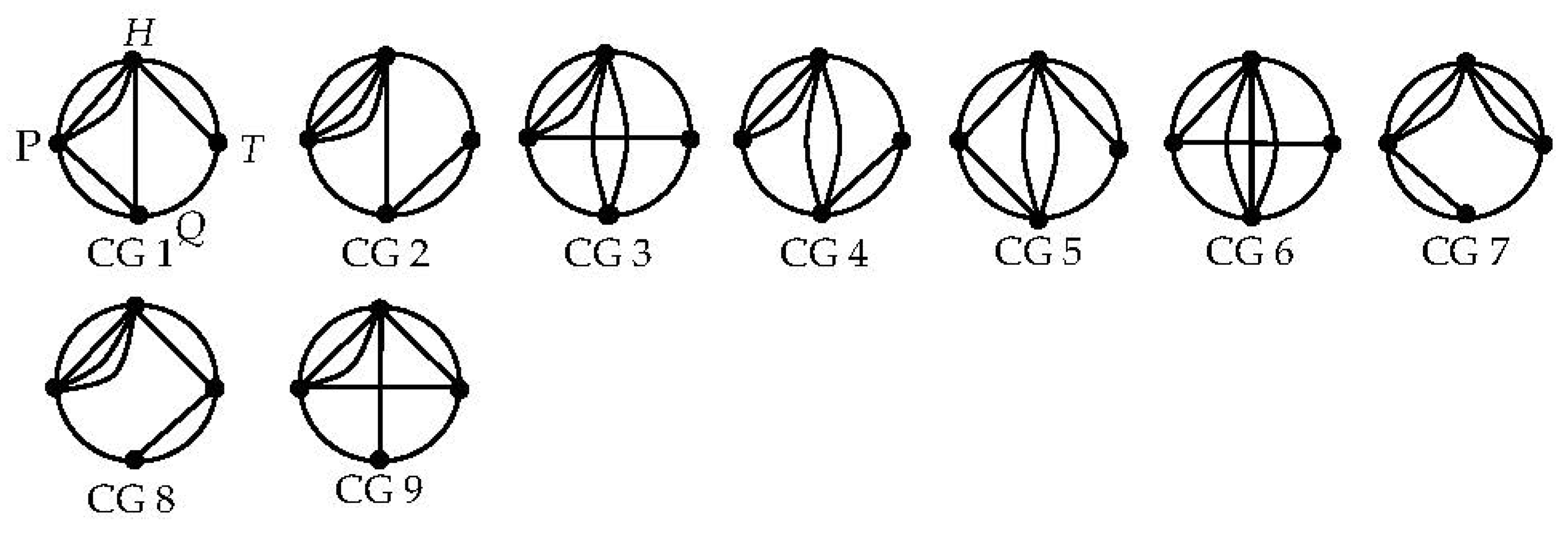
The number of curves that can be connected by the vertices representing different basic links is different and is the same as the corresponding member element number of the basic link. For example, a vertex representing H, P, Q, T and other vertices must be connected to a total of 6, 5, 4, and 3 curves. As shown in Figure 1, 9 simple CGs with 1H1P1Q1T containing 4 vertices and 9 curves, which meets the structural requirements of the CG. The difference is the arrangement of the 4 vertices on the base circle and the connection between the various vertices.
Therefore, for a CG, as long as we can accurately describe the number of vertices it contains, the number of connection curves for each vertex, and the connection method between each vertex, the CG can be uniquely determined.
2.2. Characteristic String Description for CGs
A characteristic string (CS) is an array of n strings. Each string corresponds to a vertex of the CG and includes a series of digits that represent the connection mode of the basic link represented, called connection strings. Each string of digits consists of one or more digits, where each digit represents the number of curves connected by two vertices [14,15]. Table 1 shows the CSs that describe the 9 CGs in Figure 1.
In the table, {213, 32, 211, 12} is used to describe CG 1 in Figure 1, which consists of 4 strings. The first string includes a string of digits 213 corresponding to the H vertex, indicating that the basic link H and T, Q, P are connected to each other by 2, 1, and 3 curves, respectively; Similarly, the second string, the third string, and the fourth string indicate that the basic link P and H, T, Q are connected by 3, 0, and 2 curves, respectively. The basic link Q and P, H, T are connected by 2, 1, and 1 curves, respectively. The basic link T and Q, P, H are connected by 1, 0, and 2 curves, respectively. It can be seen that a CG can be described by a CS.
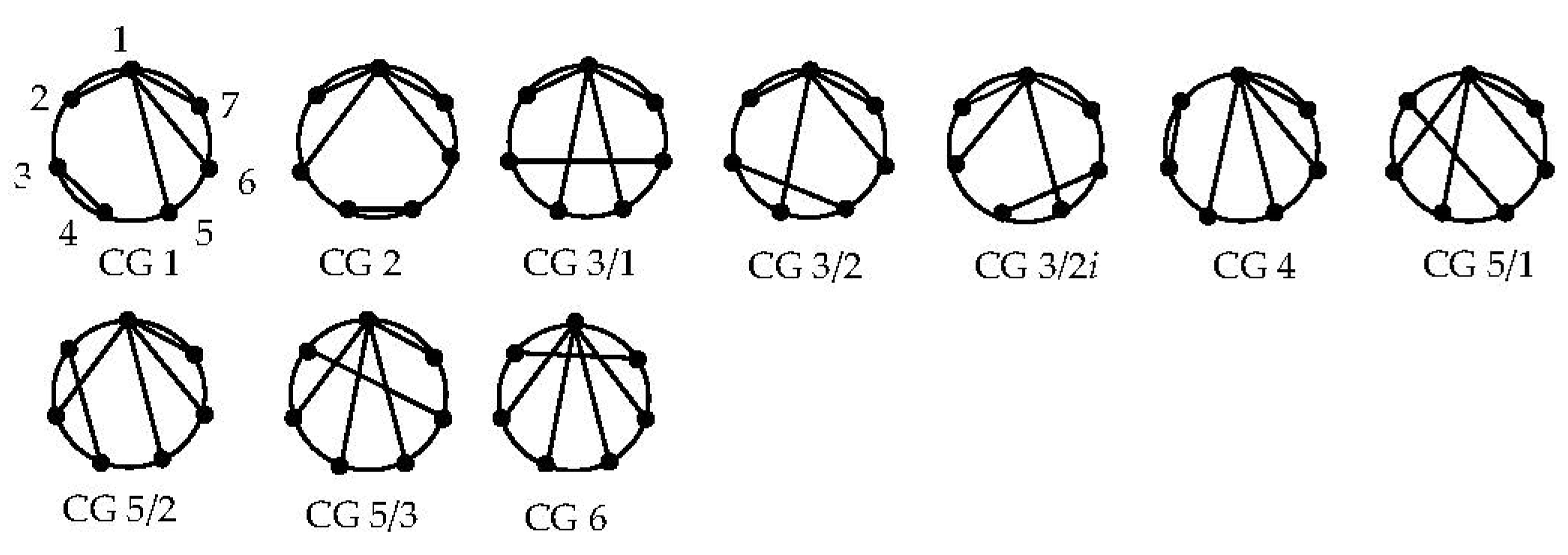
There are 6 CSs for describing the CGs with 1H6T (see Table 2), which can be used to synthesize the corresponding CGs, as shown in Figure 2.
Through observation, it is found that {2112, 21, 111, 111, 111, 111, 111, 12} with a sequence number of 3 in Table 2 can simultaneously describe the CG 3/1, CG 3/2, and CG 3/2i (where CG 3/2i is isomorphic to CG 3/2, which can be directly determined by observation); {111111, 111, 111, 111, 111, 111, 111, 111} with a sequence number of 5 can describe CG 5/1, CG 5/2, and CG 5/3 at the same time. There is a case where a CS describes multiple CGs.
This is mainly due to the complexity of the connection method of non-adjacent basic links described by {2112, 21, 111, 111, 111, 111, 111, 12} and {21111, 111, 111, 111, 111, 12}. The connection method of the middle bit of a CS with more than three digits cannot be described and explained in the CS. In order to ensure the unique correspondence between the CG of a kinematic chain and its feature description, it is necessary to find a more standardized description method.
3. Standardized Description of CGs
3.1. Component Sequence String and Component Number
According to Section 2, each CG can be described by a CS, but each CS does not only describe one CG. The main reason is that it is not possible to accurately describe the connection methods of all basic links in a CG through only CSs.
In order to facilitate the correspondence with CSs, it is common to start from the vertex at the top of the base circle and sequentially number all vertices on the base circle in a counterclockwise direction. The constructed string is called a component sequence string (CSS), and each digit therein is called a component number (CN). The CSS describing the CG with 1H6T is {1,2,3,4,5,6,7}, as shown in CG 1 in Figure 2. The CSS contains a total of seven CNs, which correspond sequentially to each string of the CS.
3.2. Connection Method Substring of CGs
The connection method substring (CMS) is an array of m (m ≤ n) strings, each string corresponding to the CN of two mutually connected nonadjacent vertices in a CG, that is, each string in the CMS includes two numbers.
The CMS is used to describe the connection relationship between nonadjacent links in a CG. It can represent the connection relationship between the middle digits of a string with a median of three or more characters in a CS. Taking the CS {2112, 21, 111, 111, 111, 111, 12} in Table 2 as an example, the CS contains a total of seven strings, including a string {2112} with four digits and a string {111} with three digits. According to the nature of the CS [14], the first and last bits of each string in the CS are connected to adjacent links, while the intermediate bit cannot be reconnected to its adjacent links. So, there are three ways to connect intermediate bits, as shown in Table 3, which correspond to the CG 3/1, CG 3/2, and CG 3/2i shown in Figure 2.
Similarly, the CS {21111, 111, 111, 111, 111, 111, 111, 12} describes three connection methods for basic links, corresponding to the CG 5/1 to CG 5/3 shown in Figure 2.
3.3. Standardized Description and Determination of CGs
In the process of CGs synthesis, it is very important to choose a suitable feature description method. A CS can describe the number, type, and connection relationship between two adjacent links in a CG, while CMSs describe the connection relationship between two nonadjacent links in a CG. It can be seen that the combination of CSs and CMSs can accurately describe the type, number, and connection relationship between basic links in a CG. As long as the valid CGs are described in terms of the ALs, all the valid CGs corresponding to the ALs can be synthesized.
Steps to determine the standardized description of the CGs are as follows:
Step 1: Determine the basic links arrangement based on the ALs.
Step 2: Determine the CS that describes the CG of the kinematic chain. The determination criteria are as follows [14,15]:
- (1)
- The number of strings contained in each CS is the same as the number of basic links in the AL, both of which are n.
- (2)
- According to the basic links arrangement, in a CS, write out the string representing the connection method of each basic link from left to right.
- (3)
- Each string in the CS includes one or several digits, and the number of digits in any string is smaller than n, that is, the number of basic links in an AL.
- (4)
- Each digit of a string representing the number of curves connected by two basic links connected to each other. The sum of the digits is equal to the number of curves that the link needs to connect. The sum of digits representing the connection method of basic links H, P, Q, and T is 6, 5, 4 and 3, respectively.
- (5)
- In a CS, the last digit of the ith (i < n) string is the same as the first digit of the (i + 1)th string, and the first digit of the first string is the same as the last digit of the nth string.
- (6)
- The sum of all the digits in the n strings of a CS is equal to 2ne.
- (7)
- The sum of the same digits in each string of a CS must be an even number.
Step 3: Determine the corresponding CMS based on the generated CS. The process of determining the CMS is as follows:
- (1)
- Number all strings in the CS sequentially to obtain a CSS;
- (2)
- Remove the first and last digits of each CS to form a new character string. Where the original bit of digits is two, it is indicated by “-”;
- (3)
- Connect the digits in the new string generated in step (2). In order to ensure that the generated CMS can draw a CG, and that the drawn CG is different but not isomorphic, the following criteria need to be satisfied:
- (a)
- The difference between the CNs of two interconnected links is greater than 1;
- (b)
- The head and tail links cannot be connected to each other, that is, the two links with CN 1 and n cannot be connected;
- (c)
- The number of curves connected to each other by two interconnected links is equal, that is, the corresponding digits in the new string generated in step (2) are the same, and different digits cannot be connected to each other;
- (d)
- In the generated CMSs, if the respective strings in the two CMSs correspond to the same without considering the sequence of the respective strings, only one is retained, and the others need to be deleted;
- (e)
- In the generated CMS, when the CNs of the two connected links repeatedly appear, the generated CMS needs to be deleted, as well as the corresponding CSs.
Since the CMS is used to describe the interconnections of digits between strings with a median of greater than or equal to 3, excluding the first and last digits, it is used to describe the connection relationship of nonadjacent basic links in the CGs of the mechanism, so conditions (a) and (b) need to be satisfied.
Since the CMS is used to describe the connection relationship of nonadjacent links in a CG, and when links are connected to each other, the corresponding connection curves must be the same, so condition (c) needs to be satisfied.
In Table 2, {2112, 21, 12, 21, 111, 111, 12} is a valid CS description of HTTTTTT, and its CMS can be described with {15, 16} and {16, 15}. However, CG 1 in Figure 2 is the CG they describe. Therefore, when determining the CMS, condition (d) needs to be satisfied, otherwise a large number of identical CGs will be generated.
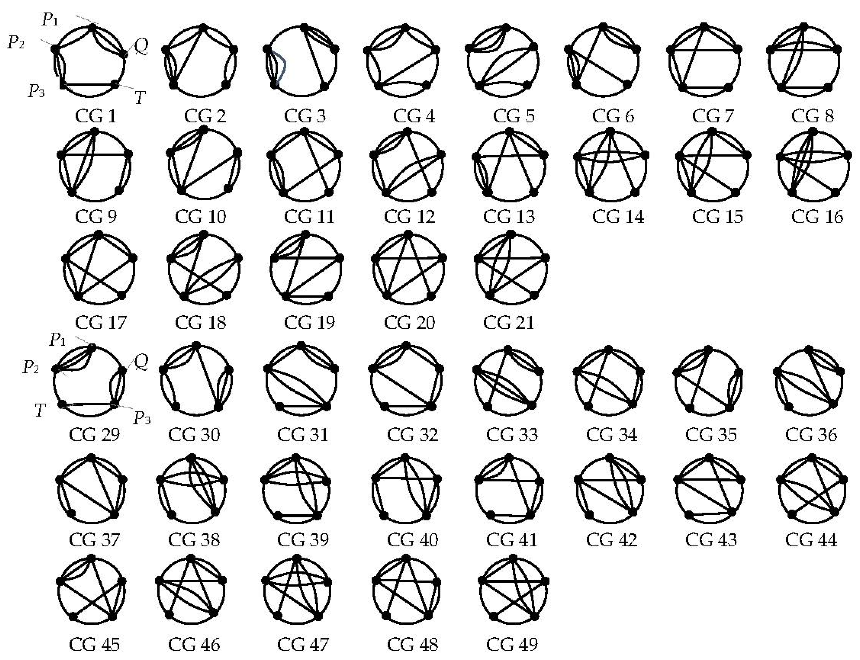
{2111, 1112, 2111, 111, 112} and {221, 1112, 221, 111, 112} can both describe CG 1 in Figure 3. They are both valid CSs for PPPTQ, but their corresponding CMSs are {13, 13, 24, 25} and {13, 24, 25}, respectively. The difference is that in the CMS of {2111, 1112, 2111, 111, 112}, the string {13} appears twice, indicating that the links with CN 1 and CN 3 need to connect two one-bar curves. In the CMS of {221, 1112, 221, 111, 112}, the string {13} only appears once, indicating that the links with CN 1 and CN 3 need to connect one two-bar curve. Therefore, in order to avoid synthesizing the same CG, condition (e) needs to be satisfied. Here, we call the CS {2111, 1112, 2111, 111, 112} an isomorphic CS of {221, 1112, 221, 111, 112}.
Using the above criteria as programming conditions, it is easy to generate all valid CMSs from a CS through a computer. Taking {2112, 21, 111, 111, 111, 12} as an example, follow the steps to determine the CMS, and sequentially obtain the CSS as {1, 2, 3, 4, 5, 6, 7}. After removing the first and last bits of each string, obtain a new string {11, -, 1, 1, 1, 1, -}. Finally, it is determined that the CMS satisfying the criteria (a)~(e) is {13,15,46}, {14,15,36}, {14,16,35}.
3.4. An Example for Synthesizing CGs
According to the theory of AL for closed mechanisms [17], 1Q1T3P is one of the ALs when the complexity of the mechanism µ is 6. Now, the corresponding effective CGs of the mechanism are synthesized. The comprehensive process is as follows:
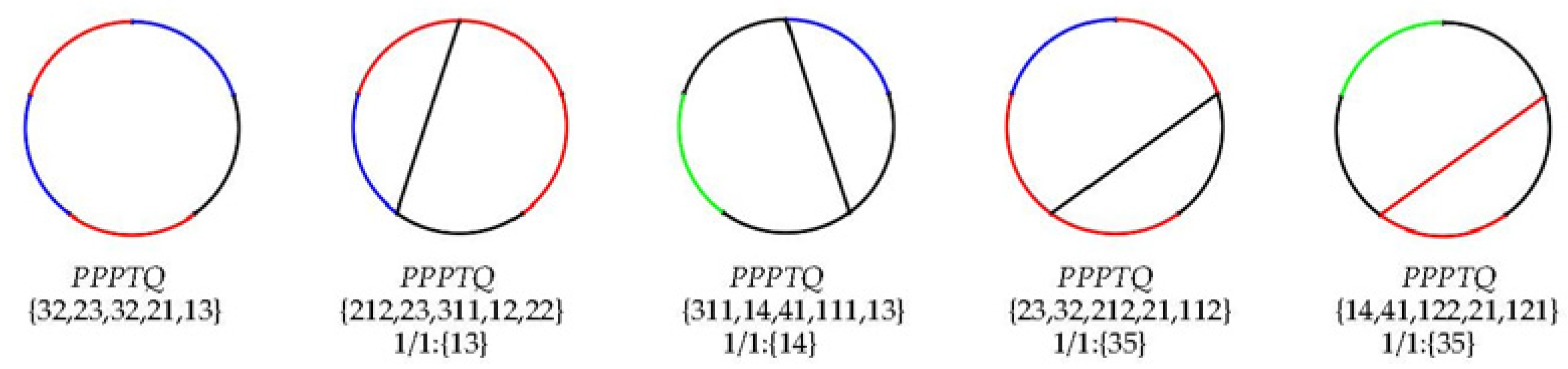
Step 1: Determine the arrangement of the basic links in 1Q1T3P. In this step, it is necessary to delete the cyclic isomorphism arrangement and then obtain two effective arrangements: PPPTQ and PPTPQ, as shown in Table 5.
Step 2: Determine the corresponding CSs for the two different basic linkage arrangements obtained above. Using the method, it is obtained that there are 28 and 21 sets of CSs for PPPTQ and PPTPQ, as shown in Table 5.
Step 3: Determine the corresponding CMS from each CS determined above according to the criteria (a) to (d), as shown in Table 5.
Step 4: Check the generated CMSs and delete the CSs and CMSs that describe the same CG according to criterion (e). In Table 5, under the basic link arrangement PPPTQ, the CSs and CMSs with No. 22 to No. 28 need to be deleted to avoid generating the same CG, which is marked with “—” in the table.
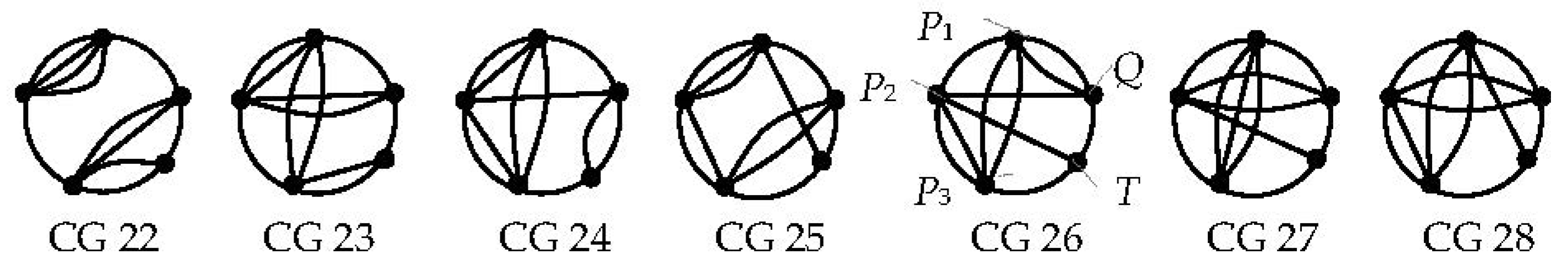
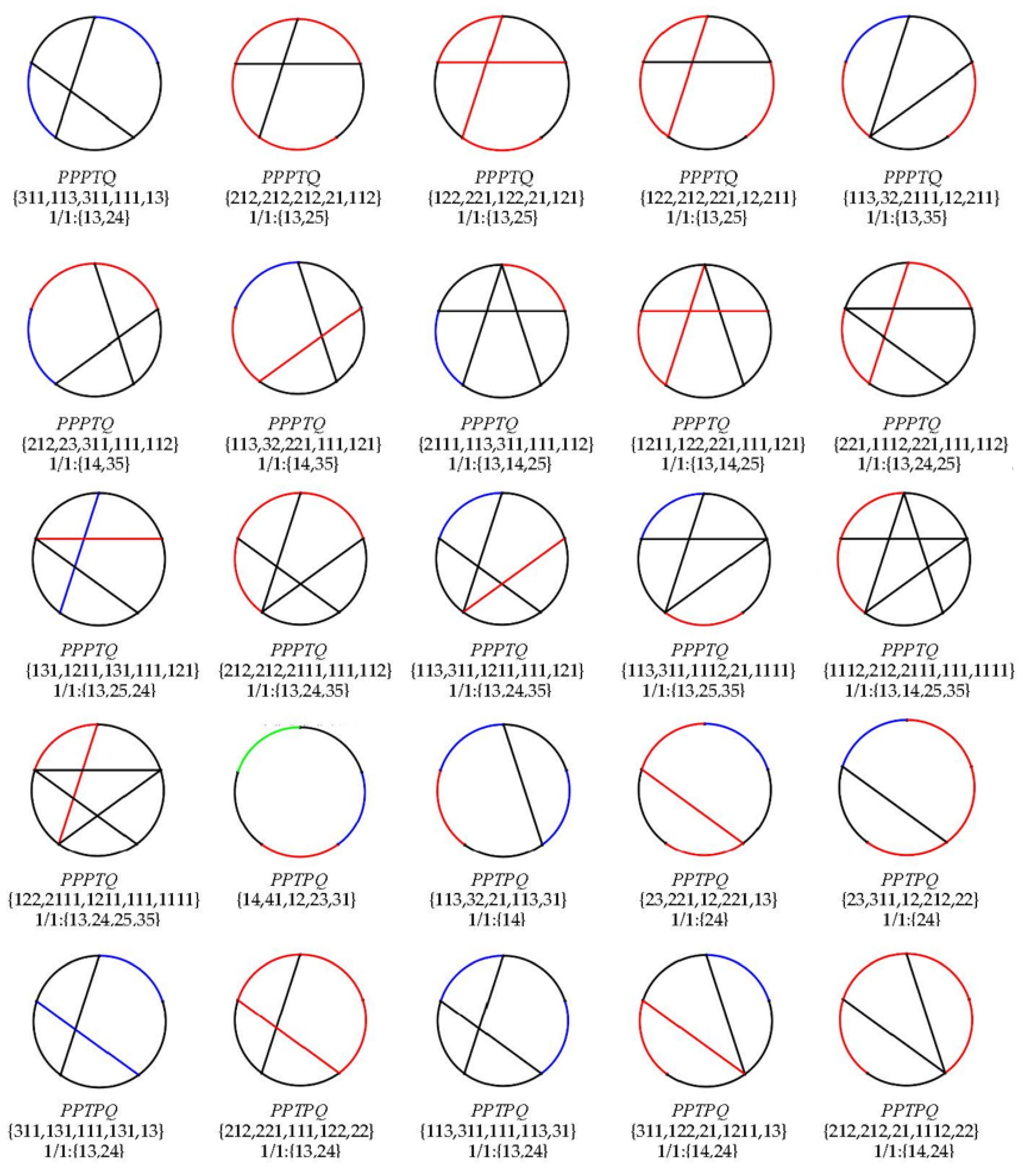
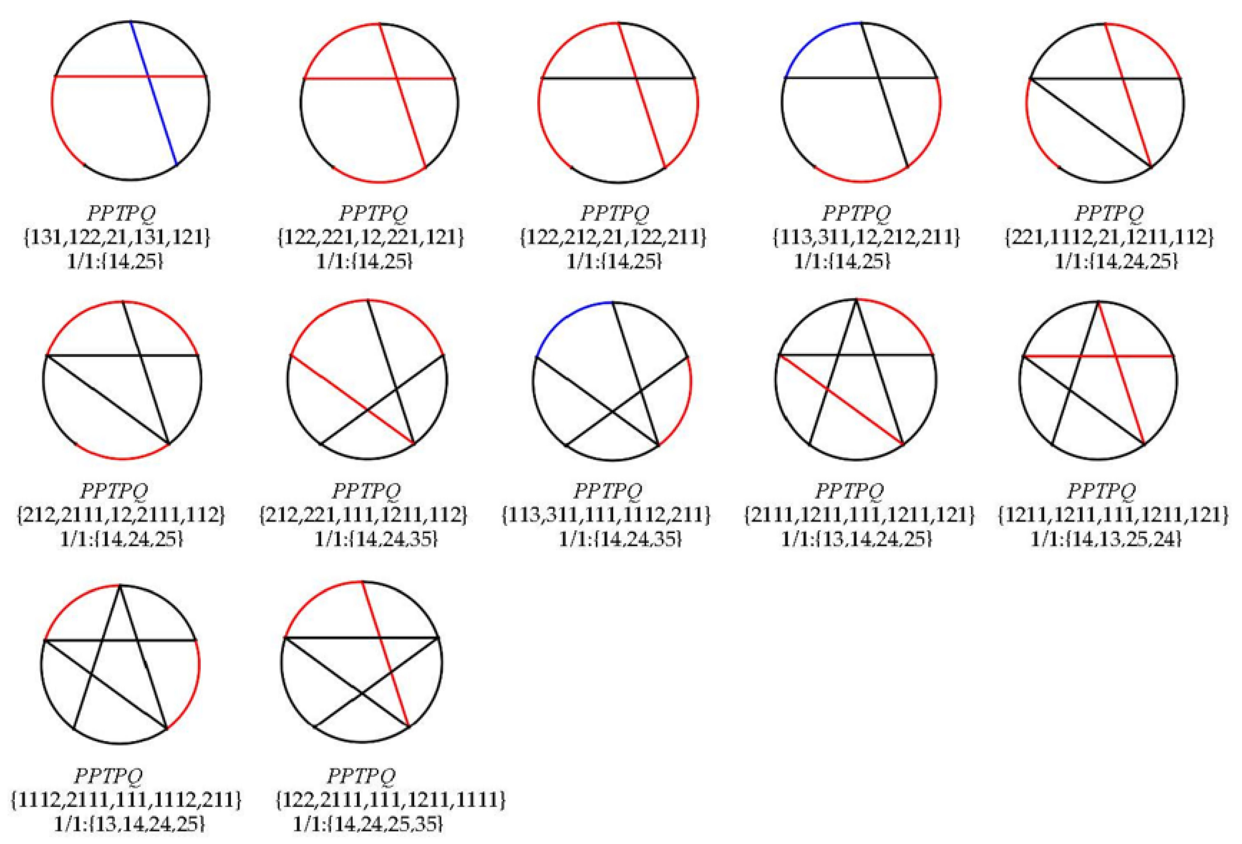
Step 5: Draw a CG of the mechanism from valid CSs and CMSs. Note that each string in a CMS only represents the link number to be connected, and the specific number of curves to be connected needs to be determined based on the numerical size at the corresponding position of the corresponding CS. Figure 3 shows all the valid CGs synthesized by 1Q1T3P, with a total of 42.
The CGs drawn from the CMs and CMSs numbered 22 to 28 in Table 5 are shown in Figure 4. By comparing them with Figure 3, it is found that they are identical to the CGs drawn from the standardized descriptions numbered 5, 8, 9, 12, 15, 16, and 14, respectively. Therefore, when determining the standardized description, it can be directly deleted, reducing the workload of subsequent judgment of pattern isomorphism.
4. Automatic Synthesis of CGs by CAD
4.1. Establishment of Functional Modules and Interface
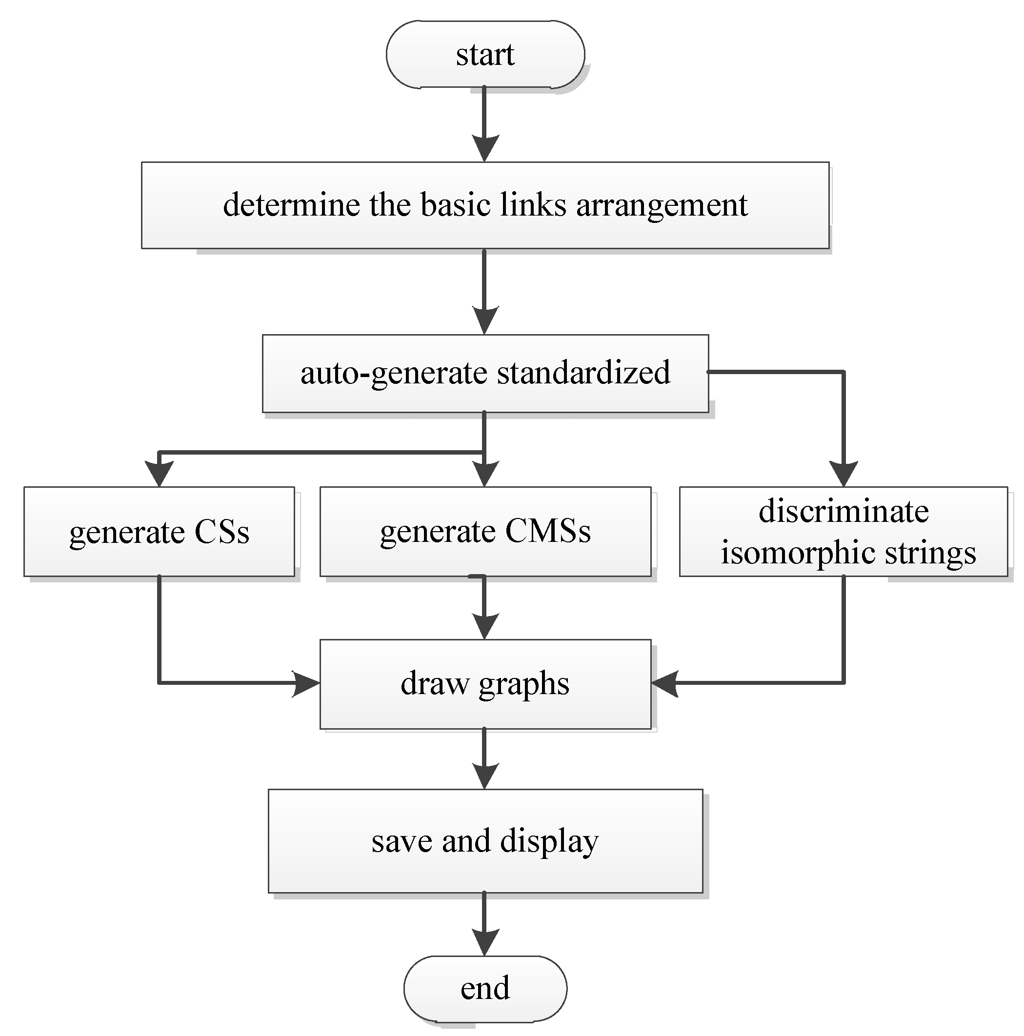
A software for automatic synthesis of CGs is created, and the design flow chart is shown in Figure 5. It has three main functions as follows:
- (1)
- Generation of basic link arrangement.
- (2)
- Generation of standardized description of CGs.
- (3)
- Automatic Drawing of CGs.
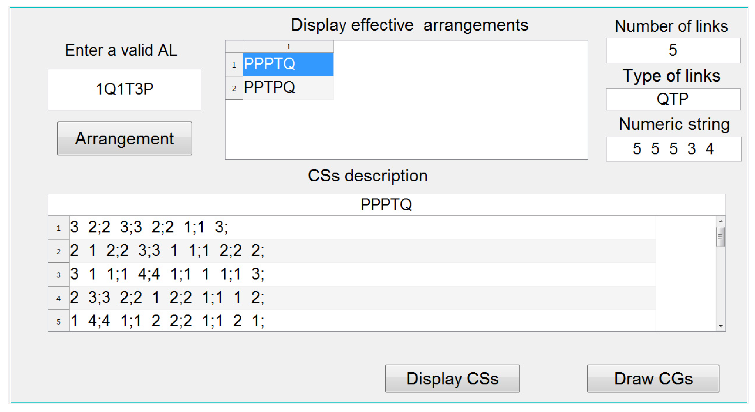
As shown in Figure 6, the main interface of the software is mainly composed of four text boxes, two list boxes, and three buttons.
Only one of the four text boxes is an input box for entering an AL. The others are display text boxes that can display the number of basic links contained in the AL, the type of links, and the digital representation of the basic link arrangement. One of the list boxes is for displaying the basic link arrangement, and the other for displaying all valid CSs of the specified basic link arrangement. Three buttons are used to control whether to execute three commands: calculating the basic link arrangement, displaying valid CSs under a specific arrangement, drawing and displaying CGs.
4.2. Algorithm of Programs in Software
4.2.1. Generating the Basic Links Arrangement
Using selective insertion method [22], the basic links arrangement of a given AL can be generated.
4.2.2. Generating the Valid CSs
According to the proposed guidelines of determining the CSs in Section 3, the CSs of an AL with certain basic links arrangement can be automatically generated.
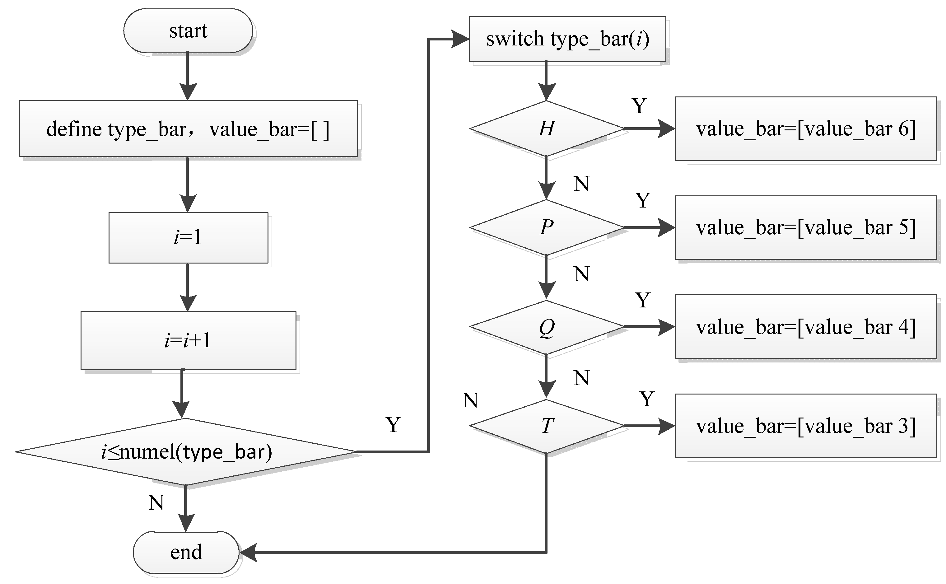
- Numeric string representation for basic links arrangement
The main function of this subroutine is to obtain the number of elements of the basic link represented by the given symbol (such as H, P, Q or T), which is a numeric representation, and store the results in an array value_bar. Figure 7 shows the flowchart for implementing the program.
- 2.
- Connection strings of different basic links
The recursive approach is adopted, and the main function of this subroutine is to decompose the specified number into a string with the sum of each number as the value.
Assuming that the number of elements of a basic link is n and denoted as n-element links, all possible connection modes are denoted as set P(n). When n = 0, the set is called empty, that is, P(0) ={ }; when n > 0, it can be denoted as i + P(n−i), where i = 1~n. The “+” sign here is not an addition symbol in mathematical operations, defined as the concatenation of arrays or strings. For example, calculate the connection string of the ternary link T, where n = 3. According to the proposed algorithm, the calculation is divided into the following steps:
Step 1: Calculate P(1) first. Since P(0) ={ }, then P(1) = 1 + P(0) = {1}.
Step 2: Calculate P(2) again. When I = 1, P(2) = 1 + P(1) = {1 1}, and when i = 2, P(2) = 2 + P(0) = {2} [2].
Step 3: Calculate P(3). The method is the same as above, then P(3) = 1 + P(2) = {1 1 1} and{1 2}, P(3) = 2 + P(1) = {2 1}, P(3) = 3 + P(0) = {3}.
So, there are four types of connection string for T: {1 1 1}, {1 2}, {2 1}, and {3}. Based on the above algorithm, the connection strings of other basic links can also be obtained.
- 3.
- Group connection strings of basic links
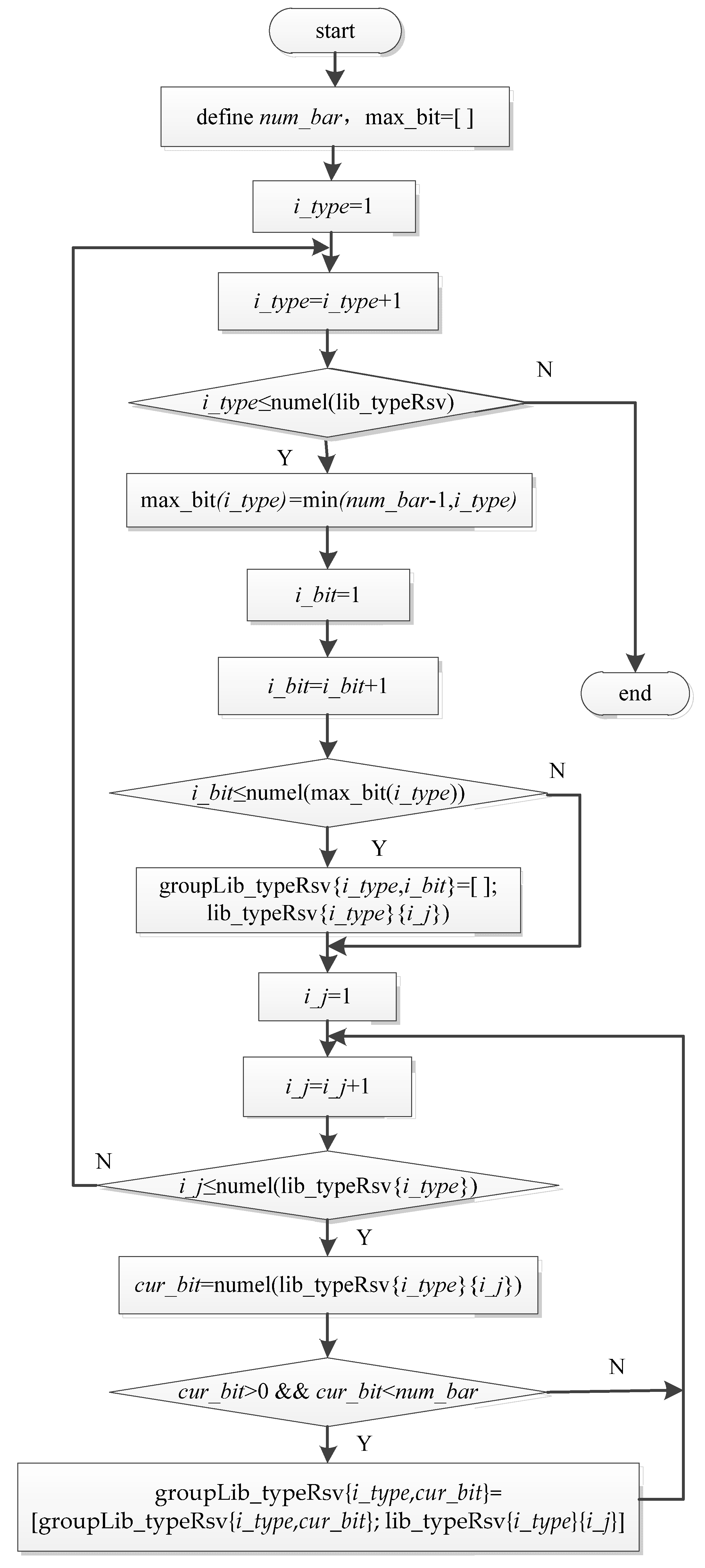
This grouping is based on the number of bits in the string. Figure 8 shows the flowchart for grouping connection strings.
From the flowchart, it can be seen that the program has defined a variable num_bar at the beginning, used to store the number of links contained in the AL to be calculated. At the same time, a one-dimensional array max_bit is defined, and its i_type element is the maximum number of bits after grouping the connection strings of link labeled i_type. The grouping results are saved in a two-dimensional cell array named groupLib_typeRsv.
According to the determination criteria for CSs in Section 3, the maximum number of bits in the connection string of each basic link is num_bar-1, because the number of bits cannot be greater than its element label number i_type. So, the maximum number of bits in each connection string is the smaller values of num_bar-1 and i_type. Taking the AL 1Q1T3P as an example, it contains five links and a total of three types of basic links, namely T, Q, and P. Then, num_bar = 5, max_bit(3) = 3, max_bit(4) = 4, max_bit(5) = 4, indicating that the maximum number of bits for the three types of links is 3, 4, and 4, respectively. Run the program, and the results are shown in Table 6.
- 4.
- Determine the bit distribution mode of each basic link connection strings
For a given basic link arrangement, to automatically generate its valid CSs, you need to first determine the bit distribution mode of each basic link connection strings it contains, then select the string that meets the bit requirements, and finally generate the CSs through the tree structure.
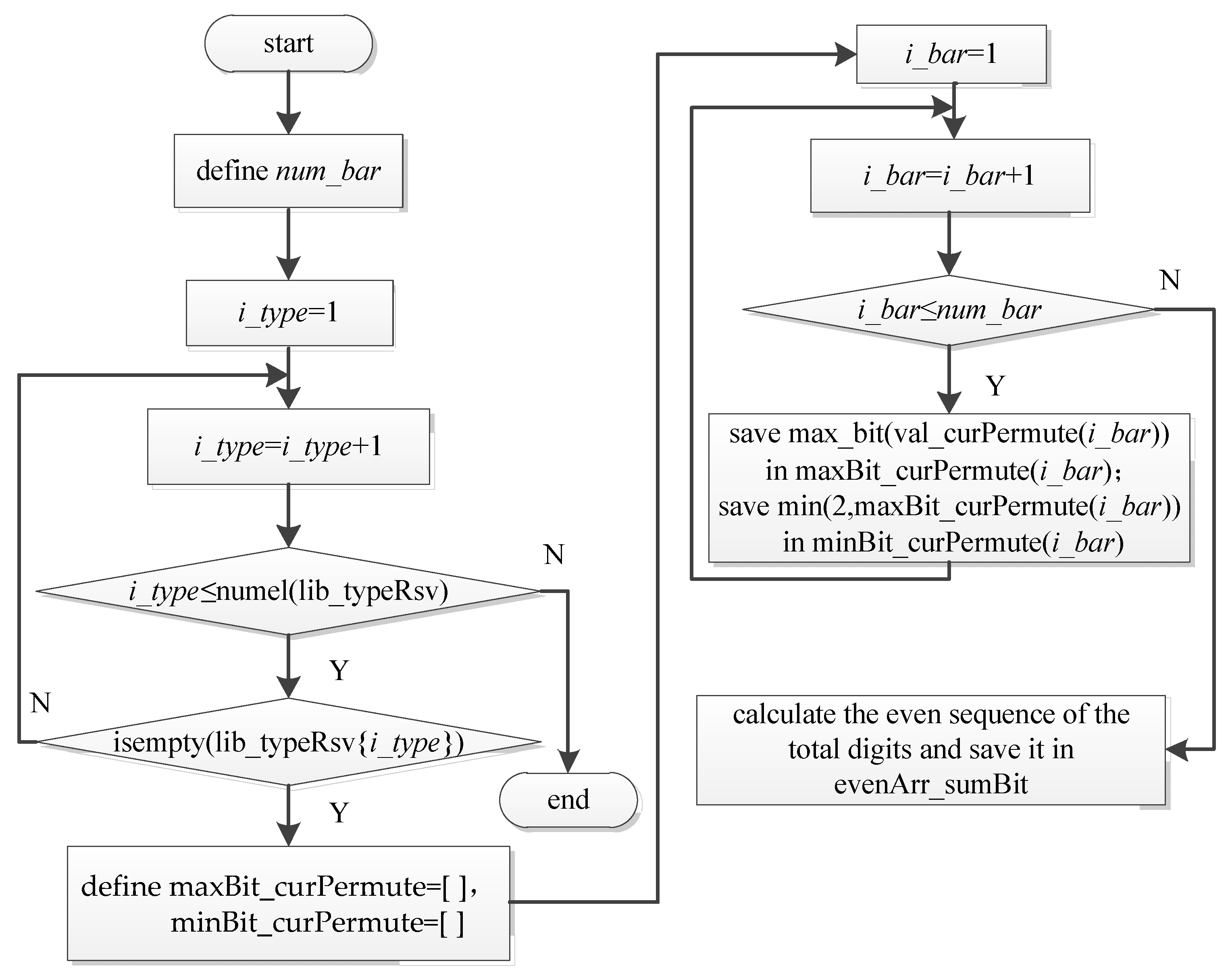
Figure 9 shows the flowchart of this subroutine. The function of this subroutine is to generate the maximum and minimum allowable bits of each connection string under the current basic links arrangement, and calculate an even sequence of the sum of the total bits, which is saved in evenArr_sumBit.
According to the relevant characteristics of a CS, the required bit distribution to be met is as follows:
- (1)
- The sum of the bits of n strings contained in each CS must be an even number, which is a multiple of 2.
- (2)
- When n is equal to 2, the number of bits in each connection string must be one.
- (3)
- When n is greater than 2, in order to ensure the closure of the drawn CG, the minimum number of bits in the connection string contained in it is two, and the maximum cannot exceed n.
So, one variable num_bar is defined in the program, used to store the number of basic links n contained in the AL to be calculated, with two arrays of maxBit_curPermute and minBit_curPermute, which stores the maximum and minimum bits for each basic link in the current basic links arrangement. Taking PPPTQ as an example, calling this subroutine will result in the maximum allowable bit maxBit_curPermute = {4 4 4 3 4}, minimum allowable bit minBit_curPermute = {2 2 2 2 2}, and even sequence of the sum of total bits evenArr_sumBit = {10 12 14 16 18}.
Then, using a recursive algorithm, based on the obtained even sequence, the effective bit distribution of each basic link connection string under the current basic link arrangement at different total bits is generated. This algorithm decomposes the specified number M (i.e., the sum of the total bits of basic links) into N numbers (i.e., the number of basic links), where the sum of these N numbers exactly equals M, and each number is within the specified range.
For PPPTQ, based on the even sequence of the sum of total bits calculated earlier and the maximum and minimum allowable bits of each connection string, the effective bit distribution can be obtained, as shown in Table 7.
Finally, based on each bit distribution mode, a tree structure is used to generate CSs. Taking the bit distribution {2 2 2 2 2} as an example, the process of generating CSs from its tree structure is shown in Table 8.
In the process of generating the tree structure, the following three situations need to be distinguished to ensure the validity of the generated CS, which are:
- (1)
- Verify whether the connection string of each basic link in the generated CS can connect with each other, that is, the last digit of the previous basic link connection string is equal to the first digit of the current basic link connection string, and the last digit of the last basic link connection string is the same as the first digit of the first basic link connection string.
- (2)
- Verify whether the sum of the same digits in the basic link connection string in the generated CS is even.
4.2.3. Generating the Valid CMSs
To design a program that automatically generates CMSs, the process is relatively complex and can be divided into the following steps according to the determination criteria for CMSs in Section 2.2:
Step 1: After removing the first and last digits of each connection string, form a new string with the remaining digits;
Step 2: For the generated new string, determine all possible situations where non-adjacent numbers in each string are connected to each other, then establish a library for CMSs;
Step 3: Check if there are valid connection methods, that is, the digits connected to each other must be equal, and the number of bits they belong to must be separated by at least one bit. Those that do not meet the requirements will be removed from the library;
Step 4: Delete completely duplicated, shifted duplicated, and reverse duplicated CMSs by detecting whether the given CMS exists in the existing library of CMSs.
Based on the above algorithm, the CMSs corresponding to the CSs of PPPTQ obtained are listed in Table 5.
4.2.4. Drawing CGs
The purpose of designing the drawing program is to automatically draw the CGs of kinematic chain according to the relationship between the automatically generated standardized description (i.e., CS and CMS) and the CG. The main functions used are the circle and plot functions. In order to facilitate computer graphics, the concept of multicolor CG is proposed, which uses different colored lines to represent different numbers of connecting curves and stores them in variables representing connecting line types. The connecting line type consists of four curves, three curves, two curves, and one curve is represented by a green, blue, red, and black line type.
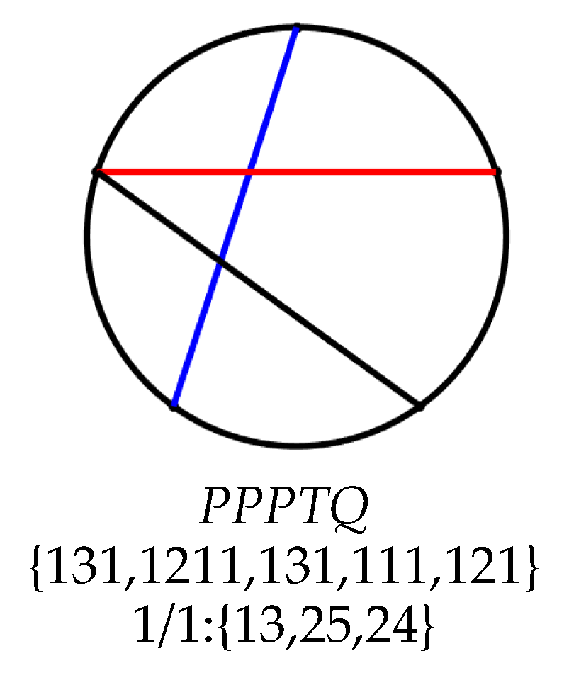
The design idea of this program is to first draw a base circle, then determine the positions of each point based on the number of basic links contained in the AL, and then connect adjacent points along the base circle according to the connecting line type corresponding to the CS. Finally, connect the related points in a straight line based on the connection relationship described by the CMS and its corresponding connecting line type. Figure 10 shows a CG and its interface display automatically drawn by the software.
Among them, PPPTQ is basic links arrangement, {131, 1211, 131, 111, 121} is the CS, and {13, 25, 24} is the CMS. The number “1/1” indicates that there is only one connection mode between nonadjacent links. If there are n modes, the numbers are “i/n” and i = 1~n respectively.
5. Application Examples of Automatic Synthesis of CGs
This method is fully implemented by computers. During program processing, intermediate variables are passed as numeric strings and stored in arrays or cell arrays. The time of the entire synthesis process is mainly determined by the number and combination of basic links in the AL. If the number of basic links is small, the corresponding calculation time will be shorter. When the total number of basic links is the same, more basic links of the same type can improve the calculation speed to a certain extent [27]. The designed software can generalize this conclusion for all ALs mentioned in Reference 10 and 27. Due to space limitations, the paper only provides two examples.
5.1. CGs of 1Q1T3P and Time Complexity Analysis
To automatically synthesize the CGs of the AL 1Q1T3P, just input 1Q1T3P in the input text box on the home screen of the software, click the “Arrangement” button, and the effective arrangement methods can be calculated as “PPPTQ” and “PPTPQ”. Select one group, respectively, and click the “Display CSs” button to display all the effective CSs of this arrangement method in the list box, as shown in Table 5 (excluding No.22 to No.28). Finally, click the “Draw CGs” button, and a total of 42 CGs are shown, as shown in Figure 11. This result is consistent with the artificially synthesized results in Figure 3. This proves that the software is simple to operate and the results are correct.
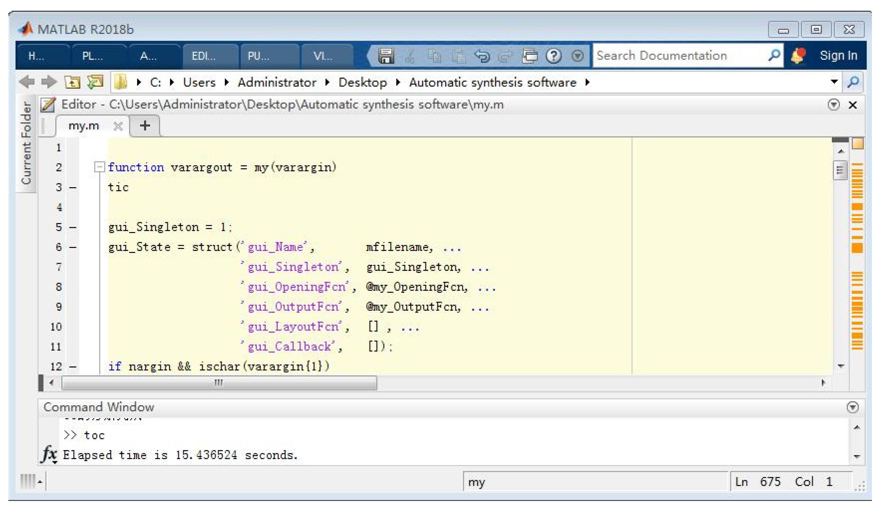
Figure 12 shows the calculation process of the AL 1Q1T3P in MATLAB. By using the “tic/toc” statement in MATLAB, the running time of the program can be calculated. In the command window, you can see that the time is 15.436524 s. It can be seen that this method is convenient and time-saving in practical applications.
5.2. CGs of 1Q6T
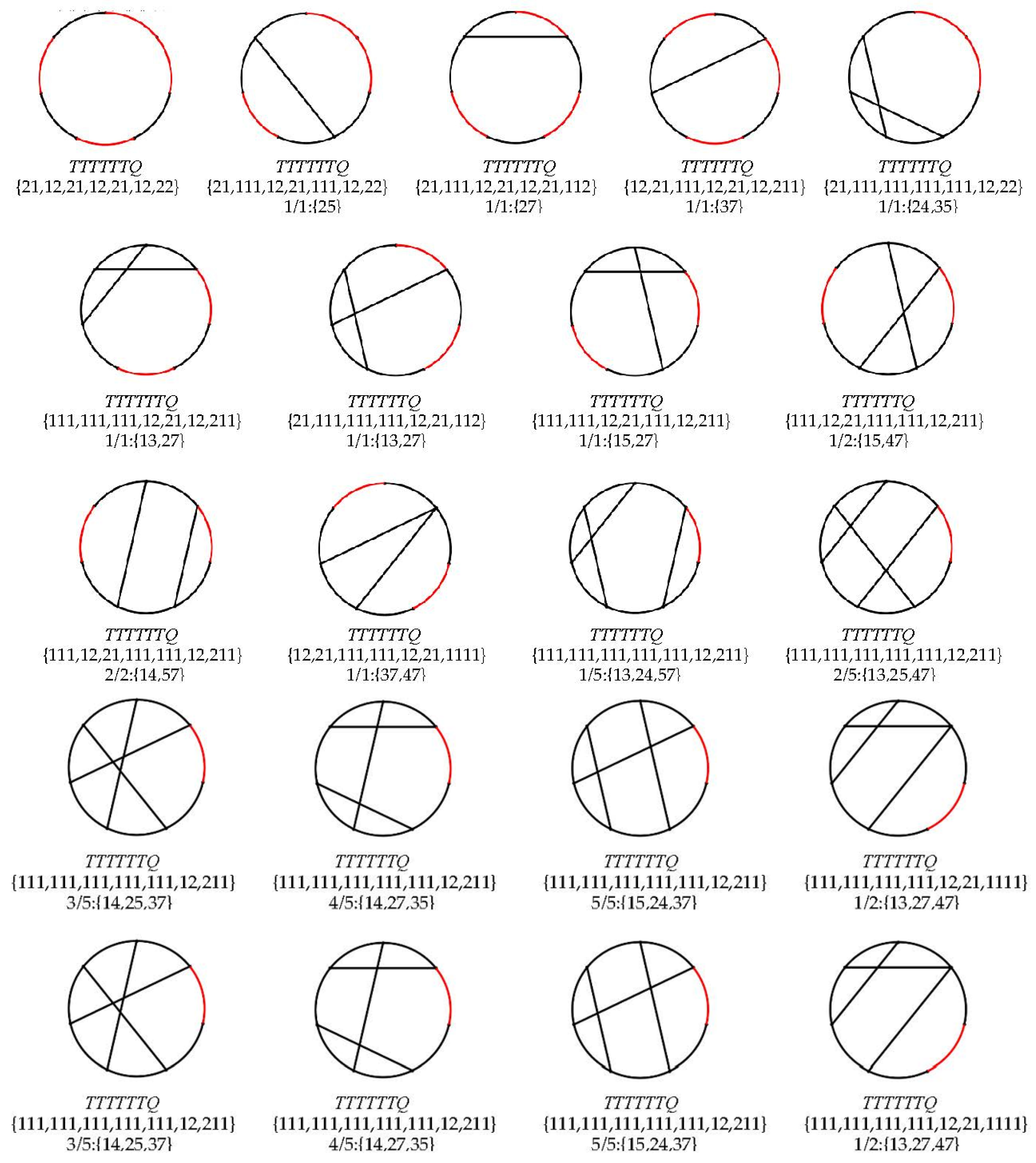
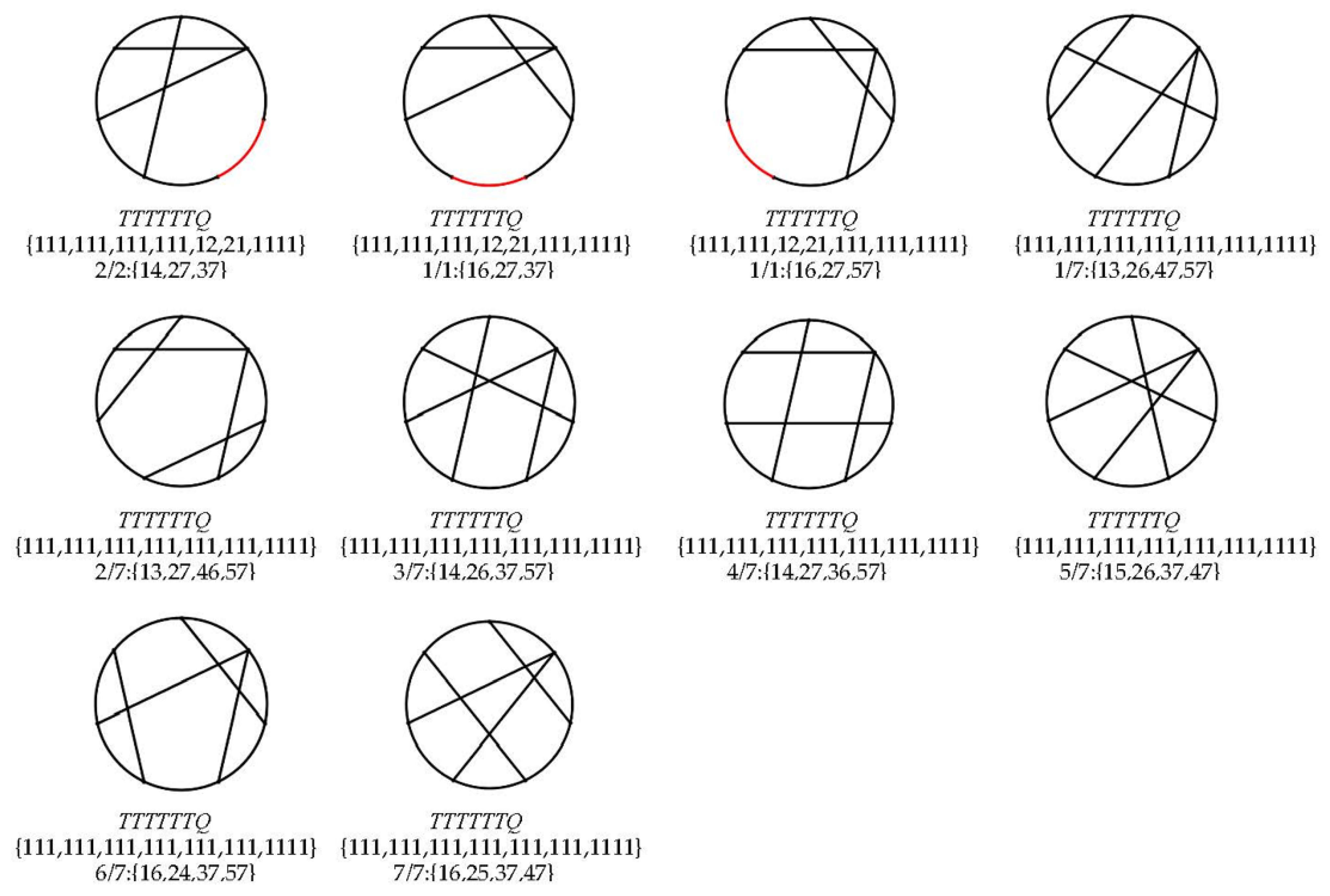
Similarly, the automatic synthesis software is run to synthesize the effective CGs of the AL 1Q6T; as 1Q6T contains six identical basic links T, there is only one effective basic arrangement, namely TTTTTTQ. There are a total of 27 distinct and non-isomorphic CGs synthesized from them, as shown in Figure 13.
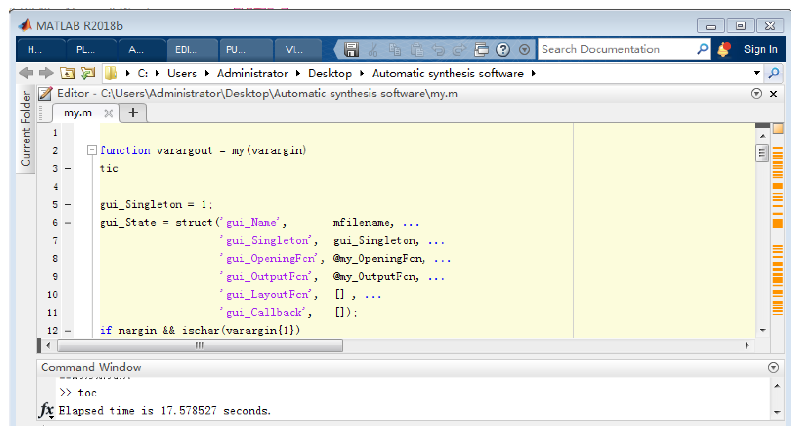
At the end of Figure 13, you can see the CS {111, 111, 111, 111, 111, 111, 1111} can synthesize seven different CGs, which are distinguished by seven different CMSs. Similarly, Figure 14 shows the calculation process of the AL 1Q6T in MATLAB. In the command window, you can see that the time is 17.578527 s.
6. Conclusions
In this article, the concept of CMS is proposed by modifying and supplementing the CSs used to describe the CG, and the solution method and related criteria are given. A CMS can describe the connection relationship between two nonadjacent links in a CG. The combination of CSs and CMSs can accurately describe the type and number of basic links in a CG, as well as the connection relationship between the links. This achieves one-to-one correspondence between a CG and its feature description, and avoids the omission and repetition of the CG during the synthesis process. Then, based on the proposed new feature description method for CGs, an automatic synthesis software for CGs is designed. The software can automatically generate effective CSs and CMSs, and can automatically draw CGs, which realizes the simplification and visualization of the complex process of CGs synthesis. Finally, taking ALs 1Q1T3P and 1Q6T as examples, running this software can automatically identify and delete isomorphic and invalid basic link arrangement, isomorphic CSs and CMs, and isomorphic CGs during the synthesis process.
Author Contributions
Methodology, Y.W.; software, Y.W. and S.C.; visualization, Z.C.; writing—original draft preparation, Y.W., S.C. and Z.C.; writing—review and editing, Y.W. and S.C.; supervision, Z.C.; project administration, Y.W.; funding acquisition, Y.W. All authors have read and agreed to the published version of the manuscript.
Funding
This research was funded by Tangshan Normal University Science Research Fund Project, grant number 2023B33, the University Science and Technology Research Project of Hebei Province, grant number ZD2020151, Tangshan Science and Technology Plan Project, grant number 20130219B. And this work was supported in part by Science and Technology Plan Project of Tangshan Science and Technology Bureau Tangshan Foundation Innovation Team of Digital Media Security under Grant 21130212D.
Data Availability Statement
Not applicable.
Acknowledgments
The authors would like to thank the Tangshan Normal University Science Research Fund Project (2023B33), Tangshan Key Laboratory of New Intelligent Sensing Technology and Science and Technology Plan Project of Tangshan Foundation Innovation Team of Digital Media Security (21130212D).
Conflicts of Interest
The authors declare no conflict of interest.
References
- Huang, L.; Wang, Y.; Pattabiraman, K.; Danesh, P.; Siddiqui, M.K.; Cancan, M. Topological indices and QSPR modeling of new antiviral drugs for cancer treatment. Polycycl. Aromat. Compd. 2022, 150, 1–22. [Google Scholar] [CrossRef]
- Wang, X.J.; Hanif, M.F.; Mahmood, H.; Manzoor, S.; Siddiqui, M.K.; Cancan, M. On computation of entropy measures and their statistical analysis for complex benzene systems. Polycycl. Aromat. Compd. 2022, 66, 1–15. [Google Scholar]
- Ullah, A.; Zeb, A.; Zaman, S. A new perspective on the modeling and topological characterization of H-Naphtalenic nanosheets with applications. J. Mol. Model. 2022, 28, 211. [Google Scholar] [CrossRef] [PubMed]
- Biggs, N.L.; Keyth, L.E.; Wilson, R.J. Graph Theory; Clarendon Press: Oxford, UK, 1976. [Google Scholar]
- Johnson, R.C. Mechanical Design Synthesis-Creative Design and Optimize, 2nd ed.; Huntington: New York, NY, USA, 1987. [Google Scholar]
- Vucina, D.; Freudenstein, F. Application of graph theory and non-linear programming to the kinematic synthesis of mechanisms. Mech. Mach. Theory 1991, 26, 553–563. [Google Scholar] [CrossRef]
- Dobrjanskyj, L.; Freudenstein, F. Some applications of graph theory to the structural analysis of mechanisms. J. Eng. Ind. 1967, 89, 153–158. [Google Scholar] [CrossRef]
- Yan, H.S.; Hsu, C.H. Contracted graphs of kinematic chains with multiple joints. Math. Comput. Model. 1988, 10, 681–695. [Google Scholar] [CrossRef]
- Jin, Q.; Yang, T.L. Theory for topology synthesis of parallel manipulators and its application to three-dimension-translation parallel manipulators. J. Mech. Des. 2004, 126, 625–639. [Google Scholar] [CrossRef]
- Lu, Y.; Leinonen, T. Type synthesis of unified planar-spatial mechanisms by systematic linkage and topology matrix-graph technique. Mech. Mach. Theory 2005, 40, 1145–1163. [Google Scholar] [CrossRef]
- Tsai, L.W. Mechanism Design: Enumeration of Kinematic Structures According to Function; CRC Press: Boca Raton, FL, USA, 2001; pp. 45–328. [Google Scholar]
- Yang, T.L.; Jin, Q.; Liu, A.X. Structural synthesis and classification of the 3DOF translational parallel robot mechanisms based on the units of single-opened-chain. Chin. J. Mech. Eng. 2002, 38, 31–36. [Google Scholar] [CrossRef]
- Gogu, G. Structural Synthesis of Parallel Robots; Part I: Methodology; Springer: New York, NY, USA, 2008; pp. 99–119. [Google Scholar]
- Moon, Y.M.; Kota, S. Automated synthesis of mechanisms using dual-vector algebra. Mech. Mach. Theory 2002, 37, 143–166. [Google Scholar] [CrossRef]
- Zhou, H.; Ting, K.L. Topological synthesis of compliant mechanisms using spanning tree theory. J. Mech. Des. 2005, 127, 753–759. [Google Scholar] [CrossRef]
- Yan, H.S.; Kang, C.H. Configuration synthesis of mechanisms with variable topologies. Mech. Mach. Theory 2009, 44, 896–911. [Google Scholar] [CrossRef]
- Yan, H.S.; Kuo, C.H. Topological representations and characteristics of variable kinematic joints. J. Mech. Des. 2006, 128, 384–391. [Google Scholar] [CrossRef]
- Martin, A.P.; Alberto, C. An automated method for type synthesis of planar linkages based on a constrained subgraph isomorphism detection. Multibody Syst. Dyn. 2007, 18, 233–258. [Google Scholar]
- Martin, A.P.; Alberto, C. Synthesis of planar multiloop linkages starting from existing parts or mechanisms: Enumeration and initial sizing. Mech. Based Des. Struct. Mach. 2008, 36, 364–391. [Google Scholar]
- Ding, H.F.; Yang, W.J.; Huang, P. Automatic structural synthesis of planar multiple joint kinematic chains. ASME J. Mech. Des. 2013, 135, 091007. [Google Scholar] [CrossRef]
- Ding, H.F.; Cao, W.A.; Cai, C.W.; Kecskemethy, A. Computer-aided structural synthesis of 5-DOF parallel mechanisms and the establishment of kinematic structure databases. Mech. Mach. Theory 2014, 83, 14–30. [Google Scholar] [CrossRef]
- Saura, M.; Celdran, A.; Dopico, D.; Cuadrado, J. Computational structural analysis of planar multibody systems with lower and higher kinematic pairs. Mech. Mach. Theory 2014, 71, 79–92. [Google Scholar] [CrossRef]
- Ding, H.F.; Cao, W.A.; Chen, Z.M.; Kecskemethy, A. Structural synthesis of two-layer and two-loop spatial mechanisms with coupling chains. Mech. Mach. Theory 2015, 92, 289–313. [Google Scholar] [CrossRef]
- Sun, L.; Cui, R.J.; Yang, W.J.; Ye, Z.Z.; Zhou, Y.Z.; Wu, C.Y. Automatic synthesis of the complete set of contracted graphs for planar kinematic chains with up to seven independent loops. Mech. Mach. Theory 2021, 156, 1–19. [Google Scholar] [CrossRef]
- Ding, L.; Cui, W. Isomorphism identification of kinematic chain topology graph based on embryonic graphs. J. Mach. Des. 2015, 11, 60–62. [Google Scholar]
- Lu, Y.; Wang, Y.; Lu, Y.; Ye, N.J. Derivation of contracted graphs with ternary/quaternary links for type synthesis of parallel mechanisms by characteristic strings. Robotica 2015, 33, 548–562. [Google Scholar] [CrossRef]
- Wang, Y.; Lu, Y. Determination of Permutation and Combination of Basic Links in Associated Linkage of Closed Mechanisms. J. Mech. Eng. 2016, 52, 130–136. [Google Scholar] [CrossRef]
Figure 1.
The 9 simple CGs with 1H1P1Q1T.

Figure 2.
The CGs with 1H6T.

Figure 3.
The valid CGs of 1Q1T3P.

Figure 4.
Some identical CGs of 1Q1T3P.

Figure 5.
The design flow chart of the software.

Figure 6.
The interface of software for synthesizing CGs with 1Q1T3P.

Figure 7.
A subprogram flow of numeric string representation for basic links arrangement.

Figure 8.
Program flowchart for grouping connection strings by bits.

Figure 9.
Program flowchart for calculating even sequence of bits sum.

Figure 10.
The interface display of automatically drawing the CG.

Figure 11.
The interface display of automatically drawing the CG s with 1Q1T3P.


Figure 12.
Calculation interface of 1Q1T3P in MATLAB.

Figure 13.
The interface display of automatic drawing the CGs with 1Q6T.


Figure 14.
Calculation interface of 1Q6T in MATLAB.


Table 1.
The CSs for describing the 9 simple CGs in Figure 1.
Table 1.
The CSs for describing the 9 simple CGs in Figure 1.
| CGs | Basic Link Arrangement | CSs |
|---|---|---|
| 1 | HPQT | {213, 32, 211, 12} |
| 2 | HPQT | {114, 41, 112, 21} |
| 3 | HPQT | {123, 311, 121, 111} |
| 4 | HQPT | {123, 31, 122, 21} |
| 5 | HQPT | {222, 22, 221, 12} |
| 6 | HQPT | {132, 211, 131, 111} |
| 7 | HPTQ | {33, 32, 21, 13} |
| 8 | HPTQ | {24, 41, 12, 22} |
| 9 | HPTQ | {213, 311, 111, 112} |
Table 2.
The CSs for describing simple CGs with 1H6T.
| No. | H | T | T | T | T | T | T |
|---|---|---|---|---|---|---|---|
| 1 | 2112 | 21 | 12 | 21 | 111 | 111 | 12 |
| 2 | 2112 | 21 | 111 | 12 | 21 | 111 | 12 |
| 3 | 2112 | 21 | 111 | 111 | 111 | 111 | 12 |
| 4 | 21111 | 12 | 21 | 111 | 111 | 111 | 12 |
| 5 | 21111 | 111 | 111 | 111 | 111 | 111 | 12 |
| 6 | 111111 | 111 | 111 | 111 | 111 | 111 | 111 |
Table 3.
The connection method of intermediate bit in a CS.
| CSs | Connection Method of Intermediate Bit |
|---|---|
| {2112, 21, 111, 111, 111, 111, 12} |  |
| {21111, 111, 111, 111, 111, 111, 12} |  |
Table 4.
The CMS describing the CG with 1H6T.
| No. | CMS |
|---|---|
| CG 1 | {15, 16} |
| CG 2 | {13, 16} |
| CG 3/1 | {14, 15, 36} |
| CG 3/2 | {14, 16, 35} |
| CG 3/2i | {13, 15, 46} |
| CG 4 | {14, 15, 16} |
| CG 5/1 | {13, 14, 16, 25} |
| CG 5/2 | {13, 15, 16, 24} |
| CG 5/3 | {13, 14, 15, 26} |
| CG 6 | {13, 14, 15, 16, 27} |
Table 5.
Standardized description of the CGs (including description of identical CGs marked with horizontal lines) with 1Q1T3P.
Table 5.
Standardized description of the CGs (including description of identical CGs marked with horizontal lines) with 1Q1T3P.
| Basic Links Arrangement | No. | CSs | CMSs |
|---|---|---|---|
| PPPTQ | 1 | {32, 23, 32, 21, 13} | —— |
| 2 | {212, 23, 311, 12, 22} | {13} | |
| 3 | {311, 14, 41, 111, 13} | {14} | |
| 4 | {23, 32, 212, 21, 112} | {35} | |
| 5 | {14, 41, 122, 21, 121} | {35} | |
| 6 | {311, 113, 311, 111, 13} | {13, 24} | |
| 7 | {212, 212, 212, 21, 112} | {13, 25} | |
| 8 | {122, 221, 122, 21, 121} | {13, 25} | |
| 9 | {122, 212, 221, 12, 211} | {13, 25} | |
| 10 | {113, 32, 2111, 12, 211} | {13, 35} | |
| 11 | {212, 23, 311, 111, 112} | {14, 35} | |
| 12 | {113, 32, 221, 111, 121} | {14, 35} | |
| 13 | {2111, 113, 311, 111, 112} | {13, 14, 25} | |
| 14 | {1211, 122, 221, 111, 121} | {13, 14, 25} | |
| 15 | {221, 1112, 221, 111, 112} | {13, 24, 25} | |
| 16 | {131, 1211, 131, 111, 121} | {13, 25, 24} | |
| 17 | {212, 212, 2111, 111, 112} | {13, 24, 35} | |
| 18 | {113, 311, 1211, 111, 121} | {13, 24, 35} | |
| 19 | {113, 311, 1112, 21, 1111} | {13, 25, 35} | |
| 20 | {1112, 212, 2111, 111, 1111} | {13, 14, 25, 35} | |
| 21 | {122, 2111, 1211, 111, 1111} | {13, 24, 25, 35} | |
| 22 | {14, 41, 1112, 21, 1111} | {35, 35} | |
| 23 | {1112, 221, 1112, 21, 121} | {13, 13, 25} | |
| 24 | {1112, 212, 2111, 12, 211} | {13, 13, 25} | |
| 25 | {113, 32, 2111, 111, 1111} | {14, 35, 35} | |
| 26 | {2111, 1112, 2111, 111, 112} | {13, 13, 24, 25} | |
| 27 | {1211, 1211, 1211, 111, 121} | {13, 13, 25, 24} | |
| 28 | {1211, 1112, 221, 111, 1111} | {13, 14, 25, 25} | |
| PPTPQ | 29 | {14, 41, 12, 23, 31} | —— |
| 30 | {113, 32, 21, 113, 31} | {14} | |
| 31 | {32, 221, 12, 221, 13} | {24} | |
| 32 | {23, 311, 12, 212, 22} | {24} | |
| 33 | {311, 131, 111, 131, 13} | {13, 24} | |
| 34 | {212, 221, 111, 122, 22} | {13, 24} | |
| 35 | {113, 311, 111, 113, 31} | {13, 24} | |
| 36 | {311, 122, 21, 1211, 13} | {14, 24} | |
| 37 | {212, 212, 21, 1112, 22} | {14, 24} | |
| 38 | {131, 122, 21, 131, 121} | {14, 25} | |
| 39 | {122, 221, 12, 221, 121} | {14, 25} | |
| 40 | {122, 212, 21, 122, 211} | {14, 25} | |
| 41 | {113, 311, 12, 212, 211} | {14, 25} | |
| 42 | {221, 1112, 21, 1211, 112} | {14, 24, 25} | |
| 43 | {212, 2111, 12, 2111, 112} | {14, 24, 25} | |
| 44 | {212, 221, 111, 1211, 112} | {14, 24, 35} | |
| 45 | {113, 311, 111, 1112, 211} | {14, 24, 35} | |
| 46 | {2111, 1211, 111, 1211, 112} | {13, 14, 24, 25} | |
| 47 | {1211, 1211, 111, 1211, 121} | {14, 13, 25, 24} | |
| 48 | {1112, 2111, 111, 1112, 211} | {13, 14, 24, 25} | |
| 49 | {122, 2111, 111, 1211, 1111} | {14, 24, 25, 35} |
Table 6.
Group results of the connection strings in 1Q1T3P.
| Bits | T | Q | P |
|---|---|---|---|
| one-bit | {3} | {4} | {5} |
| two-bit | {12}, {21} | {13}, {31}, {22} | {14}, {41}, {23}, {32} |
| three-bit | {111} | {112}, {121}, {211} | {113}, {131}, {311}, {122}, {212}, {221} |
| four-bit | {1111} | {1112}, {1211}, {2111} |
Table 7.
The bit distribution for connection methods of basic links in PPPTQ.
| Total Digits | Bit Distribution for Connection Methods of Basic Links | No. |
|---|---|---|
| 10 | {2 2 2 2 2} | 1 |
| 12 | {4 2 2 2 2}, {3 3 2 2 2}, {2 4 2 2 2}, {3 2 3 2 2}, {2 3 3 2 2}, {2 2 4 2 2}, {3 2 2 3 2}, {2 3 2 3 2}, {2 2 3 3 2}, {3 2 2 2 3}, {2 3 2 2 3}, {2 2 3 2 3}, {2 2 2 3 3}, {2 2 2 2 4} | 14 |
| 14 | {4 4 2 2 2}, {4 3 3 2 2}, {3 4 3 2 2}, {4 2 4 2 2}, {3 3 4 2 2}, {2 4 4 2 2}, {4 3 2 3 2}, {3 4 2 3 2}, {4 2 3 3 2}, {3 3 3 3 2}, {2 4 3 3 2}, {3 2 4 3 2}, {2 3 4 3 2}, {4 3 2 2 3}, {3 4 2 2 3}, {4 2 3 2 3}, {3 3 3 2 3}, {2 4 3 2 3}, {3 2 4 2 3}, {2 3 4 2 3}, {4 2 2 3 3}, {3 3 2 3 3}, {2 4 2 3 3}, {3 2 3 3 3}, {2 3 3 3 3}, {2 2 4 3 3}, {4 2 2 2 4}, {3 3 2 2 4}, {2 4 2 2 4}, {3 2 3 2 4}, {2 3 3 2 4}, {2 2 4 2 4}, {3 2 2 3 4}, {2 3 2 3 4}, {2 2 3 3 4} | 35 |
| 16 | {4 4 4 2 2}, {4 4 3 3 2}, {4 3 4 3 2}, {3 4 4 3 2}, {4 4 3 2 3}, {4 3 4 2 3}, {3 4 3 2 3}, {4 4 2 3 3}, {4 3 3 3 3}, {3 4 3 3 3}, {4 2 4 3 3}, {3 3 4 3 3}, {2 4 4 3 3}, {4 4 2 2 4}, {4 3 3 2 4}, {3 4 3 2 4}, {4 2 4 2 4}, {3 3 4 2 4}, {2 4 4 2 4}, {4 3 2 3 4}, {3 4 2 3 4}, {4 2 3 3 4}, {3 3 3 3 4}, {2 4 3 3 4}, {3 2 4 3 4}, {2 3 4 3 4} | 26 |
| 18 | {4 4 4 3 3}, {4 4 4 2 4}, {4 4 3 3 4}, {4 3 4 3 4}, {3 4 4 3 4} | 5 |
Table 8.
Tree structure for the generation of CSs.
| Bit Distribution | {2 2 2 2 2} |
|---|---|
| P |  |
| P | |
| P | |
| T | |
| Q |
Disclaimer/Publisher’s Note: The statements, opinions and data contained in all publications are solely those of the individual author(s) and contributor(s) and not of MDPI and/or the editor(s). MDPI and/or the editor(s) disclaim responsibility for any injury to people or property resulting from any ideas, methods, instructions or products referred to in the content. |
© 2023 by the authors. Licensee MDPI, Basel, Switzerland. This article is an open access article distributed under the terms and conditions of the Creative Commons Attribution (CC BY) license (https://creativecommons.org/licenses/by/4.0/).
Share and Cite
MDPI and ACS Style
Wang, Y.; Chen, S.; Chen, Z. Feature Description Method for Contracted Graphs of Kinematic Chains and Automatic Synthesis by CAD. Symmetry 2023, 15, 1559. https://doi.org/10.3390/sym15081559
AMA Style
Wang Y, Chen S, Chen Z. Feature Description Method for Contracted Graphs of Kinematic Chains and Automatic Synthesis by CAD. Symmetry. 2023; 15(8):1559. https://doi.org/10.3390/sym15081559
Chicago/Turabian StyleWang, Ying, Shuang Chen, and Zhipeng Chen. 2023. "Feature Description Method for Contracted Graphs of Kinematic Chains and Automatic Synthesis by CAD" Symmetry 15, no. 8: 1559. https://doi.org/10.3390/sym15081559
Note that from the first issue of 2016, this journal uses article numbers instead of page numbers. See further details here.