
Analysis of Consolidation by Vertical Drain with Vacuum Preloading Based on Axisymmetric Biot’s Consolidation Theory
1
College of Civil Engineering, Zhejiang University of Technology, Hangzhou 310014, China
2
School of Engineering, University of Warwick, Coventry CV4 7AL, UK
3
Zhejiang Key Laboratory of Civil Engineering Structures & Disaster Prevention and Mitigation Technology, Hangzhou 310014, China
*
Author to whom correspondence should be addressed.
Symmetry 2023, 15(6), 1245; https://doi.org/10.3390/sym15061245
Submission received: 15 May 2023
/
Revised: 4 June 2023
/
Accepted: 7 June 2023
/
Published: 12 June 2023
(This article belongs to the Special Issue Symmetry in the Finite Element Method and Finite Element Analysis)
Abstract
:A model of consolidation for a single-drain well under vacuum preloading, based on Biot’s axisymmetric theory and considering the “real strain” hypothesis, was established using the finite element method. Degenerating the consolidation equation of real strain yielded the Barron’s classical free strain and equal strain equations. The free strain and equal strain finite element models were derived by imposing boundary and constraint conditions on the real strain FEM model. The validation of the simulation process confirmed that the numerical model achieved consistent outcomes, with the theoretical values postulating its effectiveness. The real strain model revealed the Mandel–Cryer effect of soil near the vertical drain during the initial vacuum preloading consolidation process, causing the effective stress to increase more than the effective stress generated by the vacuum pressure and leading to a greater reduction in the void ratio. This phenomenon is one of the reasons for clogging during the vacuum preloading process. However, the free strain and equal strain models cannot produce this effect because they cannot describe the coupling between soil deformation and fluid flow. The parameter analysis of the real strain model showed that as Poisson’s ratio for soil decreased, the consolidation rate of soil also decreased, while the Mandel–Cryer effect of soil increased.
1. Introduction
Vacuum preloading is a widely used technique to accelerate the consolidation rate of foundations. Extensive research has been conducted on vertical drain well consolidation theory to predict the consolidation process of foundations during vacuum preloading, resulting in significant achievements, which is a typical axisymmetric problem in soil mechanics [1]. Barron proposed two assumptions, namely free strain consolidation and equal strain consolidation, based on the different strain forms of vertical drain well consolidation [2]. Barron and Richart established the unit cell theory, that represents a single drain surrounded by a soil annulus under the two assumptions. They concluded that the results of the average consolidation degree were almost identical under the two assumptions [3]. Yoshikuni deduced a detailed equation for the free strain consolidation of the sand-drain foundation based on Barron’s solution, which comprehensively considers radial and vertical combined seepage [4]. Hansbo improved the consolidation solution based on Darcy’s law under Barron’s equal strain assumption and obtained the radial consolidation degree at any depth of the sand-drain foundation [5]. However, these methods fail to analyze the lateral deformation of the soil and reflect the non-uniform settlement deformation of the soil. Hird converted the sand-well drain system into a 2D sand-wall drain at a later point [6]. Indraratna acquired equivalent methods for the analysis of plane strain and axisymmetric strain of sand drains [7,8]. Zhao developed a plane strain solution that can consider the lateral deformation of sand-wall foundations based on the equal strain assumption [9]. Li derived the free strain solution of sand-wall drains and discovered that the solution of equal strain consolidation approximated for plane strain conditions is quite similar to the strict free strain consolidation solution [10].
The above solutions all rely on Terzaghi–Rendulic’s consolidation theory, which employs only one diffusion equation to describe the seepage consolidation process. The theory assumes constant total stresses during consolidation, which lacks rigor despite the convenience of obtaining analytical solutions. In contrast, Biot proposed a rigorous three-dimensional coupled seepage consolidation theory that accurately describes the relationship between pore water pressure dissipation and soil skeleton deformation [11]. By using Biot’s theory, Mandel and Cryer analyzed the consolidation of semi-infinitely deep foundations and spherical symmetric bodies, respectively, and discovered an increase in static pore water pressure above the proper pressure value at a particular position during the early consolidation stage [12,13]. Laboratory experiments confirmed this phenomenon, called the Mandel–Cryer effect [14]. Changes in total stress necessarily link to the Mandel–Cryer effect, which Terzaghi–Rendulic’s consolidation theory cannot explain.
The existing solutions for analyzing the consolidation theory of vertical drain with vacuum preloading are not rigorously based on Biot’s consolidation theory, and most of their formulas are complicated to solve. Nonetheless, obtaining analytical solutions via Biot’s consolidation theory for other conditions is challenging, which makes numerical simulation an increasingly important tool for studying consolidation of vertical drains [15,16]. Scholars have derived and used the finite element method of Biot’s consolidation theory to analyze the consolidation of saturated soft clay foundations [17,18]. To explore the differences between Biot’s consolidation theory and that of Terzaghi–Rendulic in analyzing consolidation via vertical drain with vacuum preloading, this paper proposes a finite element method based on Biot’s theory to simulate soil consolidation under three deformation modes: free strain, equal strain, and real strain, and assesses the classical solution’s applicability by comparing surface settlement, pore water pressure, the void ratio, and the overall consolidation degree. Additionally, it preliminarily analyzes the influence of model parameters, such as Poisson’s ratio and the drain spacing ratio (the effective drain spacing divided by the effective mandrel diameter), on the consolidation process.
2. Analytical Solution of Vacuum Preloading Problem
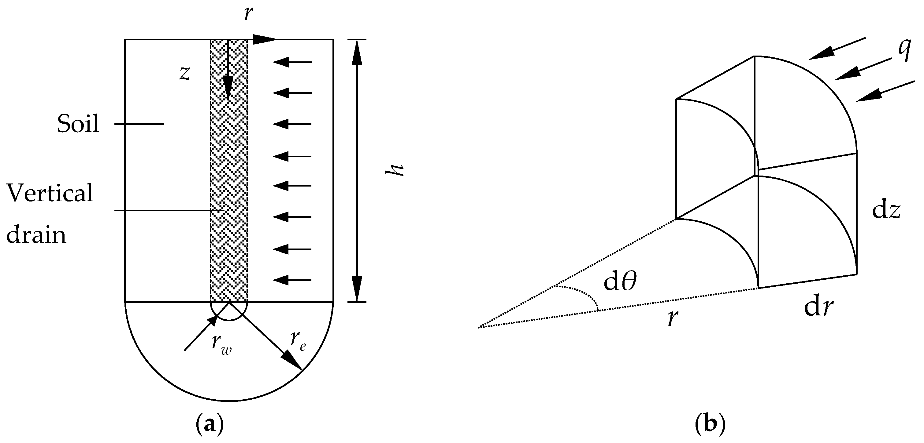
The analysis model for vertical drains with vacuum preloading is presented in Figure 1a. Here, h represents the soil thickness, rw is the vertical drain’s radius, and re is the external radius of the soil. The model assumes that the boundary at the bottom, top, and outer area is entirely impermeable. The vertical drain initiates the consolidation process by applying an instantaneous vacuum load. The model considers a vertical drain as a perfectly smooth and rigid body, while the influence of gravity is neglected. The fundamental premises for the consolidation through vertical drains are [2]:
- (1)
- The soil is homogeneous and fully saturated.
- (2)
- Soil particles and water are incompressible, and the change of unit soil volume is equal to the change of pore water volume.
- (3)
- The seepage of water in the soil obeys Darcy’s law.
Figure 1b depicts the unit body of the model in the cylindrical coordinate system. The Biot’s consolidation equilibrium differential equation of fully saturated soil when the body forces are neglected is presented as follows:
In the equation, , , and represent the effective stress in the radial direction r, tangential direction θ, and vertical direction z, represents the shear stress, and u represents the pore pressure.
Assuming elastic homogenous soil, the effective stress components can be represented as:
where represents the volumetric strain, .
Substituting Equation (2) into Equation (1), the balance equation expressed by strain can be expressed as:
The continuity of the saturated soil is also considered, where the compressed volume of unit soil per unit time is equal to the volume of water flowing out from the same unit soil in the same period. This leads to the continuity equation, which can be obtained as:
The satisfaction of equilibrium Equations (3) and (4) by the pore pressure and displacement at any location in a fully saturated soil is necessary, as they form a strict axisymmetric coupled seepage consolidation theory. Terzaghi–Rendulic’s consolidation theory serves as the basis of Barron’s approach to this phenomenon. Additionally, he introduced two assumptions for consolidation through vertical drains: (1) only vertical deformation of soil occurs without lateral deformation and (2) two deformation modes, equal strain or free strain [2], are present. The equal strain mode envisages the existence of a rigid soil foundation, whereby the soil surface remains planar throughout the consolidation deformation, signifying that the vertical strain of all points on an identical horizontal plane within a foundation are identical. Conversely, in the free strain mode, the vertical deformation of the soil’s foundation is unrestrained, resulting in uneven soil settlement owing to varying consolidation rates at each location, even though the shear deformation that follows does not impact the consolidation rate.
Since lateral deformation is neglected for both equal strain and free strain, the soil only needs to meet the vertical equilibrium Equation (1) or (3), and the volumetric strain of the soil can be expressed as . Consequently, Equations (3) and (4) can be simplified as:
Under the assumption of free strain, the shear deformation does not influence the consolidation rate, the term with shear strain in Equation (5) is supposed to be equal to zero, and therefore we assume the shear modulus G is zero, and the relation between shear modulus, elastic modulus, and Poisson’s ratio, G = E/[2(1 + μ)], does not hold. Equation (5) can be simplified to:
From Equation (7), we can obtain:
The left term of the equation: is the total stress of the calculation region, which will not change with time for the case of free strain, so we can obtain:
Conversely, under the assumption of equal strain, the vertical effective strain within the soil remains constant on an identical horizontal plane, and the soil has no shear strain, so Equation (5) can also be simplified to Equation (7), and we can obtain Equation (8) as well. However, is not zero in Equation (8) for the case of equal strain. Upon integrating Equation (8), both sides along the horizontal plane, we arrive at the following equilibrium equation:
Here, represents the vertical force exerted by the base on the soil, which remains unchanged. Consequently, the relationship between pore pressure and vertical strain can be obtained as:
where is the average pore pressure, .
The boundary conditions are given as follows:
- When 0 < t < ∞ and r = re (impermeable surface), ∂u/∂r = 0 (as the impermeable surface is without seepage).
- When 0 < t < ∞ and r = rw (permeable surface), u = −80 kPa (due to the applied vacuum load on the permeable surface).
The initial condition is:
When t = 0 and 0 < r ≤ R, u = 0.
3. Finite Element Model
3.1. Axisymmetric Biot’s Consolidation Model (Real Strain Consolidation Model)
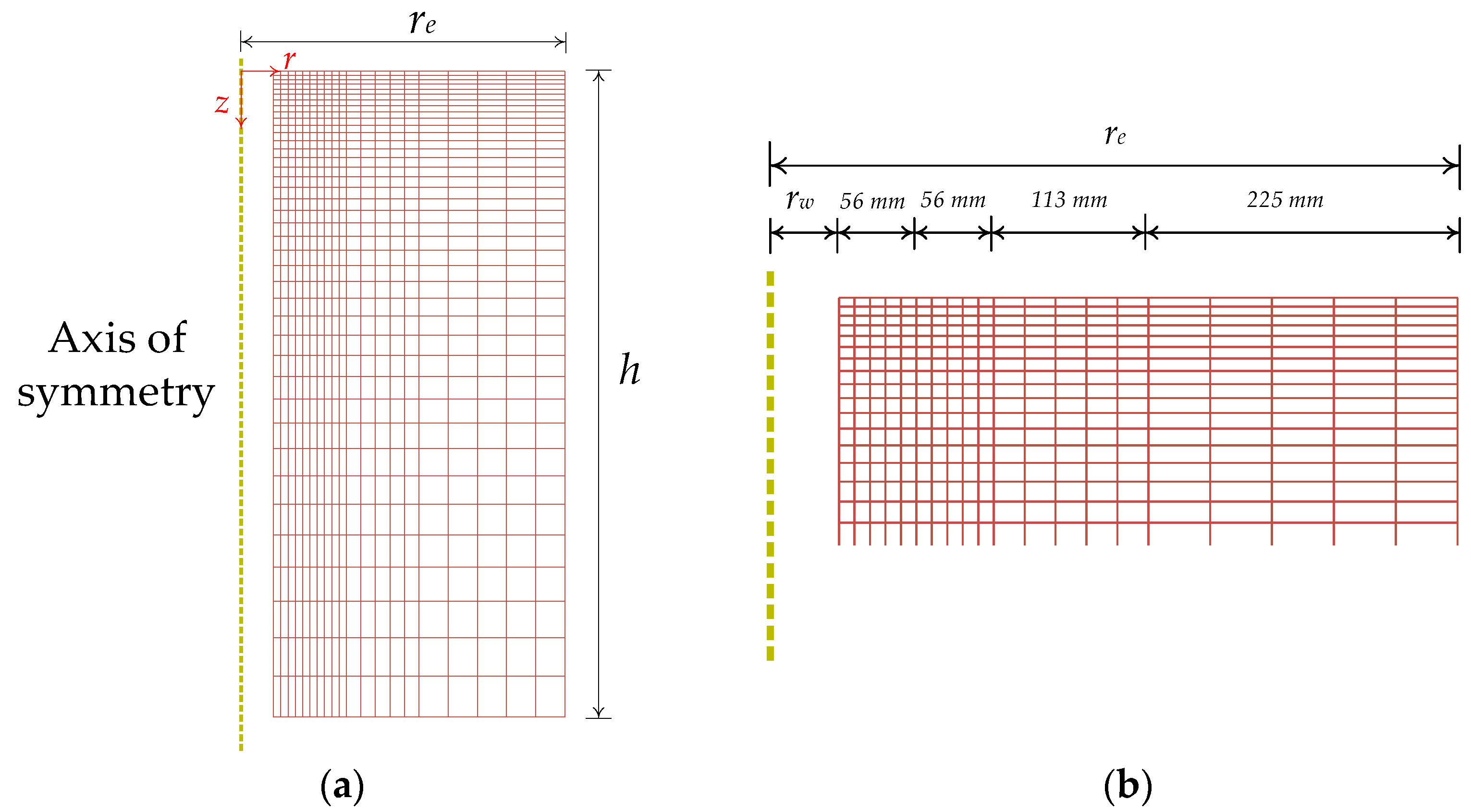
In this study, Abaqus software was utilized to solve the equations of consolidation, consisting of Equations (3) and (4) for vertical drain with vacuum preloading, under the axisymmetric Biot’s consolidation conditions (henceforth referred to as the “real strain” model). The axisymmetric soil model displayed in Figure 2a was created with respective dimensions of rw = 0.05 m, re = 0.5 m, and h = 1 m. The soil model involves Wenzhou saturated soft clay that was simulated with a linear elastic model, having a Poisson’s ratio μ = 0.3, and secant compression represented by Es1-2 = 1.8 MPa. For the finite element simulation, an elastic modulus is necessary, calculated as E = Es(1 – μ − 2μ2)/(1 − μ) = 1.35 MPa. Furthermore, the permeability coefficient was k = 3.6 × 10⁻¹⁰ m/s and the initial void ratio was e0 = 2.56. The physical properties of Wenzhou clay are listed in Table 1.
(1) Mesh Division
Several studies on finite element meshing of consolidation by vertical drain have been conducted by various scholars, such as Xie, Chen, and Deng [19,20,21,22]. From their findings, two essential conclusions can be drawn. Firstly, the horizontal element size of the soil surrounding the vertical drain has a significant impact on the level of consolidation achieved—larger horizontal elements result in faster consolidation. Secondly, to obtain excess static pore pressure results with high accuracy, the mesh in the depth direction of the soil needs to be subdivided near the top surface. To balance the need for a realistic reflection of soil seepage and the calculation speed, the soil depth direction employs single-bias seeding, which creates 40 elements with a bias ratio of 20. The seeds are more densely distributed near the top and gradually become sparser towards the bottom. Furthermore, the radial direction is divided into four areas (as per Figure 2b). Each of the four areas is divided into five uniform elements—seeds near the vertical drain are dense, and the distance between them progressively increases further out. Structured meshing was adopted here, and the mesh type CAX4P (4-node axisymmetric quadrilateral, biquadratic displacement, and bilinear pore pressure) was selected. The resulting finite element mesh can be observed in Figure 2.
(2) Mesh Convergence Study
Regarding mesh density, we conducted a comparative analysis of five different grid schemes, as shown in Table 2.
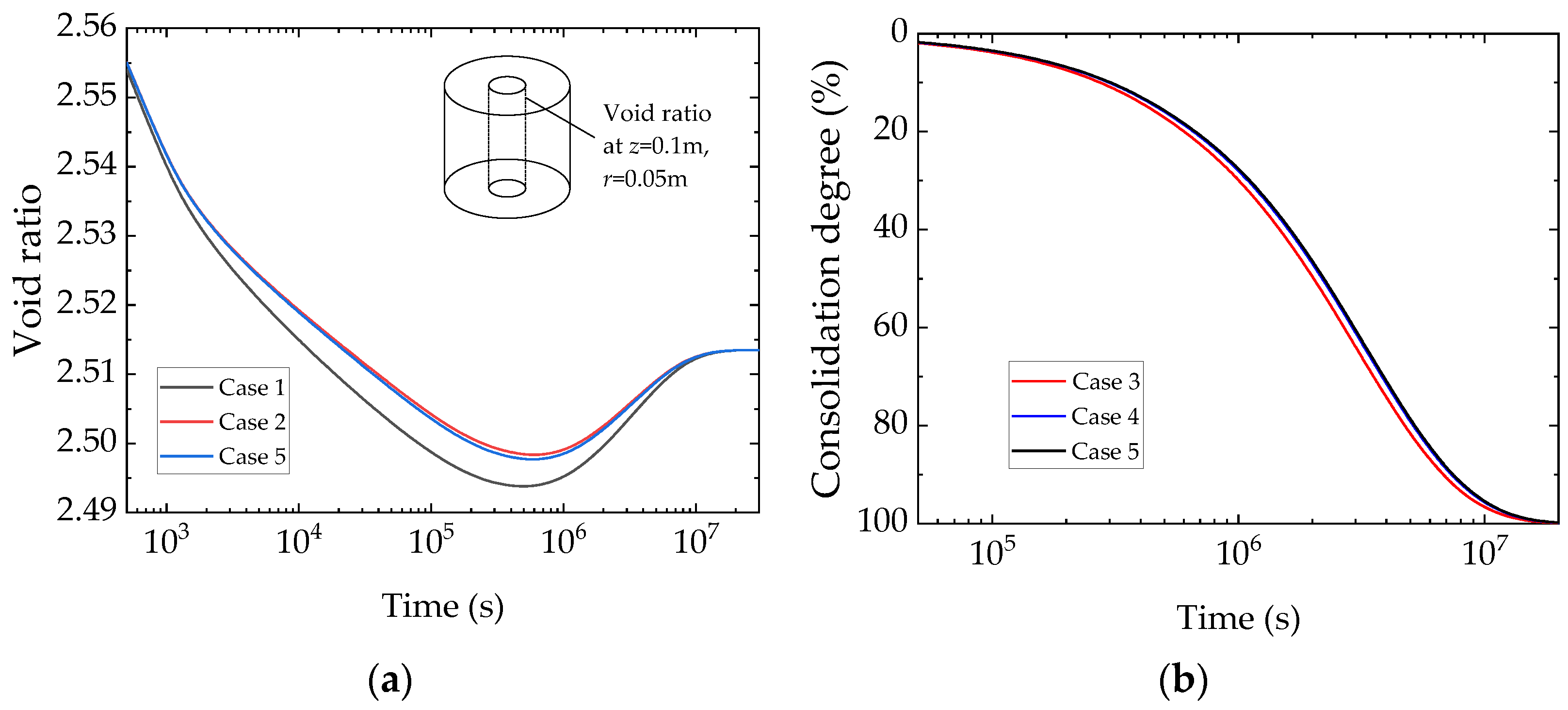
The horizontal gridding for Cases 1, 2, and 5 was the same, while the vertical gridding differed. Figure 3a displays the results of the void ratio at z = 0.1 m and r = 0.05 m for the foundation under the three cases. The results indicated that the vertical ground mesh spacing affected the void ratio in the shallow region.
For Cases 3, 4, and 5, the vertical griding remained constant, while the horizontal gridding varied. The results of the consolidation degree of the foundation for the three cases are displayed in Figure 3b. It was identified that coarse grid spacing in the horizontal direction led to errors.
Based on the above analysis, we concluded that the mesh used in this article (Case 5) was reasonable, and the numerical scheme yielded converged results when using either the same mesh or a more finely divided mesh.
(3) Analysis Step Settings
In the initial analysis step, the model’s boundary conditions were established by imposing impermeability on the top, bottom, and right boundaries. The horizontal displacement of the left and right boundaries, as well as the vertical displacement of the bottom, were limited.
A consolidation analysis step was set after the initial analysis step. The consolidation analysis step falls under the “Soils” category, with a time length of 4 × 10⁷ s. It is important to note that during “Soils” analysis, a relationship existed between meshing and time stepping. A very small time step may lead to abnormal fluctuations in pore pressure. Therefore, the initial incremental step was determined using the following equation [23].
In the equation, ΔL is the distance between the mesh nodes near the draining surface (i.e., disturbance), γw is the unit weight of water, E is the elastic modulus of the soil, and k is the permeability coefficient of the soil. This paper’s model adopted: ΔL = 12 mm, γw = 104 N/m3, E = 1.35 MPa, and k = 3.6 × 10⁻¹⁰ m/s. The initial incremental step Δt was set to 500 s, which satisfied the condition Δt ≥ 490 s.
Finally, the consolidation analysis began with the instantaneous application of a pore pressure of −80 kPa on the left boundary of the model, simulating the instantaneously applied vacuum pressure.
3.2. Barron’s Equal Strain Consolidation Model
Barron’s equal strain consolidation model introduced in this section relies on two assumptions, as outlined in Section 2: (1) soil deforms only in the vertical direction without lateral deformation and (2) the soil surface remains flat throughout the consolidation deformation process. To attain the first assumption, we limited the horizontal displacement of the soil, while we implemented a rigid body on the soil surface that bears a “Hard Contact” with the soil to satisfy the second assumption. This modification to the real strain model, presented in Section 3.1, yielded Barron’s equal strain consolidation model.
3.3. Barron’s Free Strain Consolidation Model
The Barron’s free strain consolidation model also necessitates two assumptions: (1) the soil deforms solely in the vertical direction without lateral deformation, and (2) shear deformation has no bearing on the consolidation rate. To meet assumption 1, we curtailed the horizontal displacement of the soil, and to uphold assumption 2, we assigned a zero-shear stiffness value to the soil, thus precluding shear deformation from affecting the consolidation rate. In Abaqus, G = E/[2(1 + μ)] is decoupled by using the ‘Engineering Constants’ type of elastic, which set the parameters to E1 = E2 = E3 = E, Nu12 = Nu13 = Nu23 = μ, and G12 = G13 = G23 = 1 × 10⁻³⁰. The real strain model was altered in this manner to arrive at Barron’s free strain consolidation model.
3.4. Model Validation
Barron derived an equation expressing the average degree of consolidation, assuming equal strain as:
In the equation: , , and n is the drain spacing ratio, .
Equation (12) represents the consolidation equation under the assumption of free strain. In this study, a numerical solution to this equation was obtained through the implementation of the finite difference method using MATLAB programming. To accomplish this, the soil body was discretized into M equally sized layers in the radial direction, ranging from 0 ≤ r ≤ re, with a step size of dx. Nodes were numerically identified, indexed 1 to M + 1, from the inside to the outside of the soil mass. Similarly, time was also discretized into N equally timed steps, with a time step size of dt, allowing equal division of the total consolidation time with the indexing of the time nodes from 1 to N + 1. Denoting the pore water pressure of a node by , wherein idx represents the distance from the symmetry axis at time kdt, we can obtain the following:
Substituting Equations (16)–(18) into Equation (12), we can obtain:
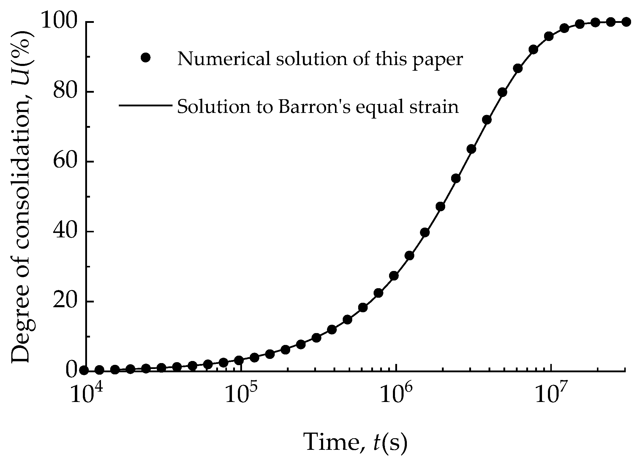
The curve of the consolidation degree over time, assuming equal strain, is displayed in Figure 4. The plot compares the results of using Barron’s solution of Equation (15) with the numerical solution of the model described in Section 3.2. As Figure 4 shows, our numerical simulations closely matched the theoretical values, providing strong evidence of the accuracy and usefulness of our model.
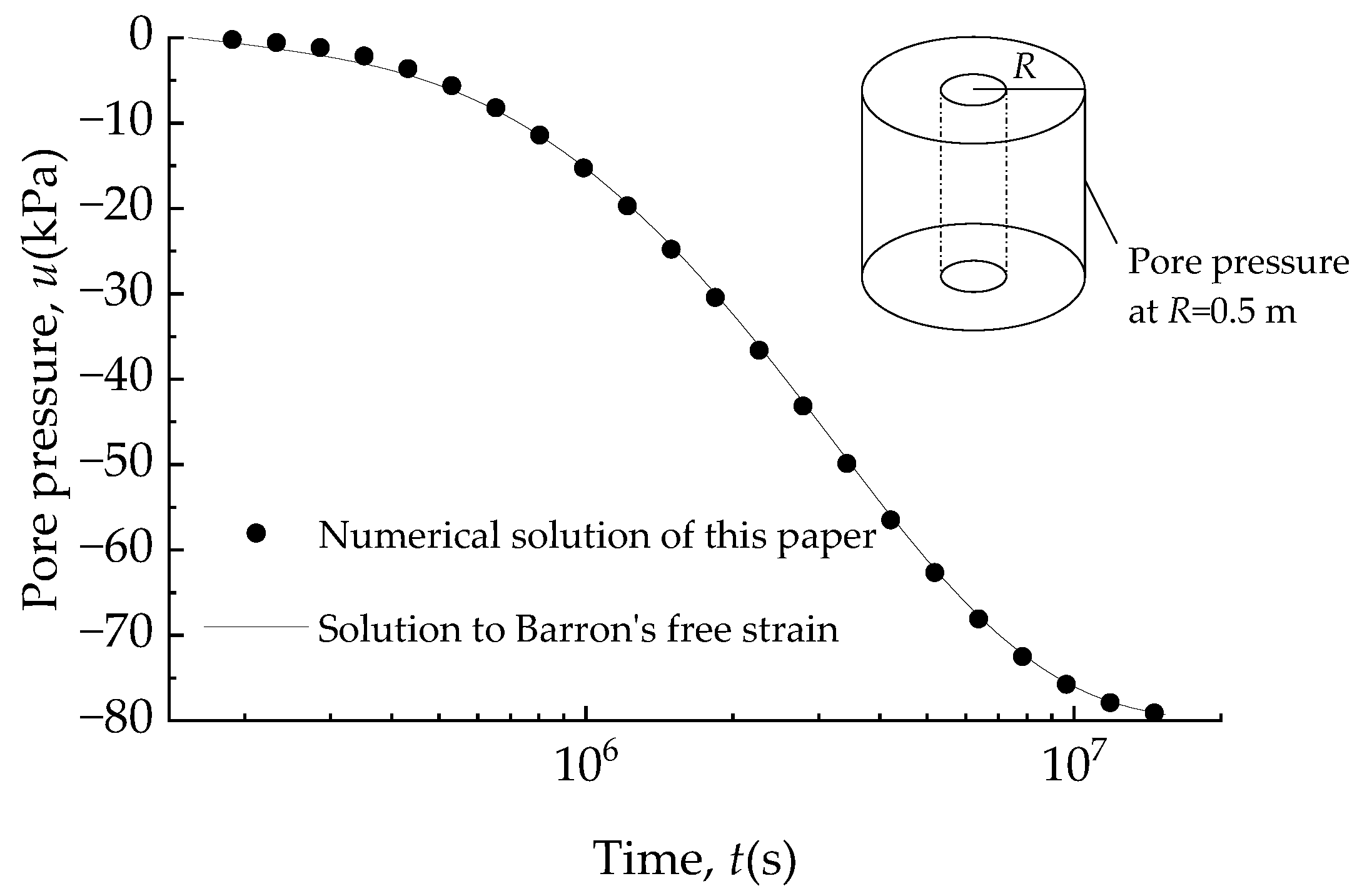
Figure 5 presents the curve of pore pressure with consolidation time at R = 0.5 m, assuming free strain. This graph compares the theoretical values calculated using Barron’s solution of Equation (19) with the results of our numerical model, which was discussed in detail in Section 3.3. The simulated values from our model closely aligned with the theoretical values, demonstrating the effectiveness of our numerical simulations. Overall, our simulations provided reliable predictions of the consolidation degree and the pore pressure over time.
4. Numerical Simulation Results and Analysis
The present study utilized real strain and its corresponding degraded models, including equivalent strain and free strain, as outlined in Section 3. The Abaqus finite element program was employed for computational purposes, leading to the acquisition of essential findings pertaining to settlement, pore water pressure, the void ratio, and the degree of consolidation in the model.
4.1. Settlement Deformation Process and Stress Spatial Distribution
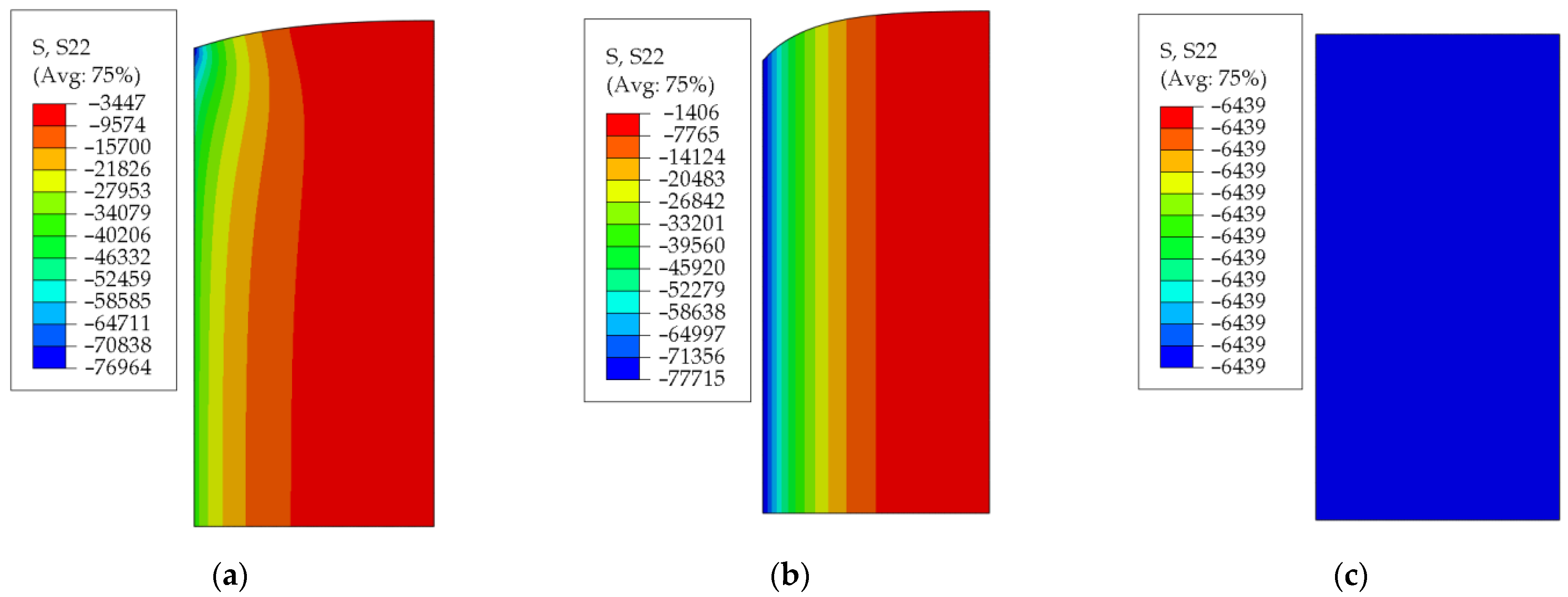
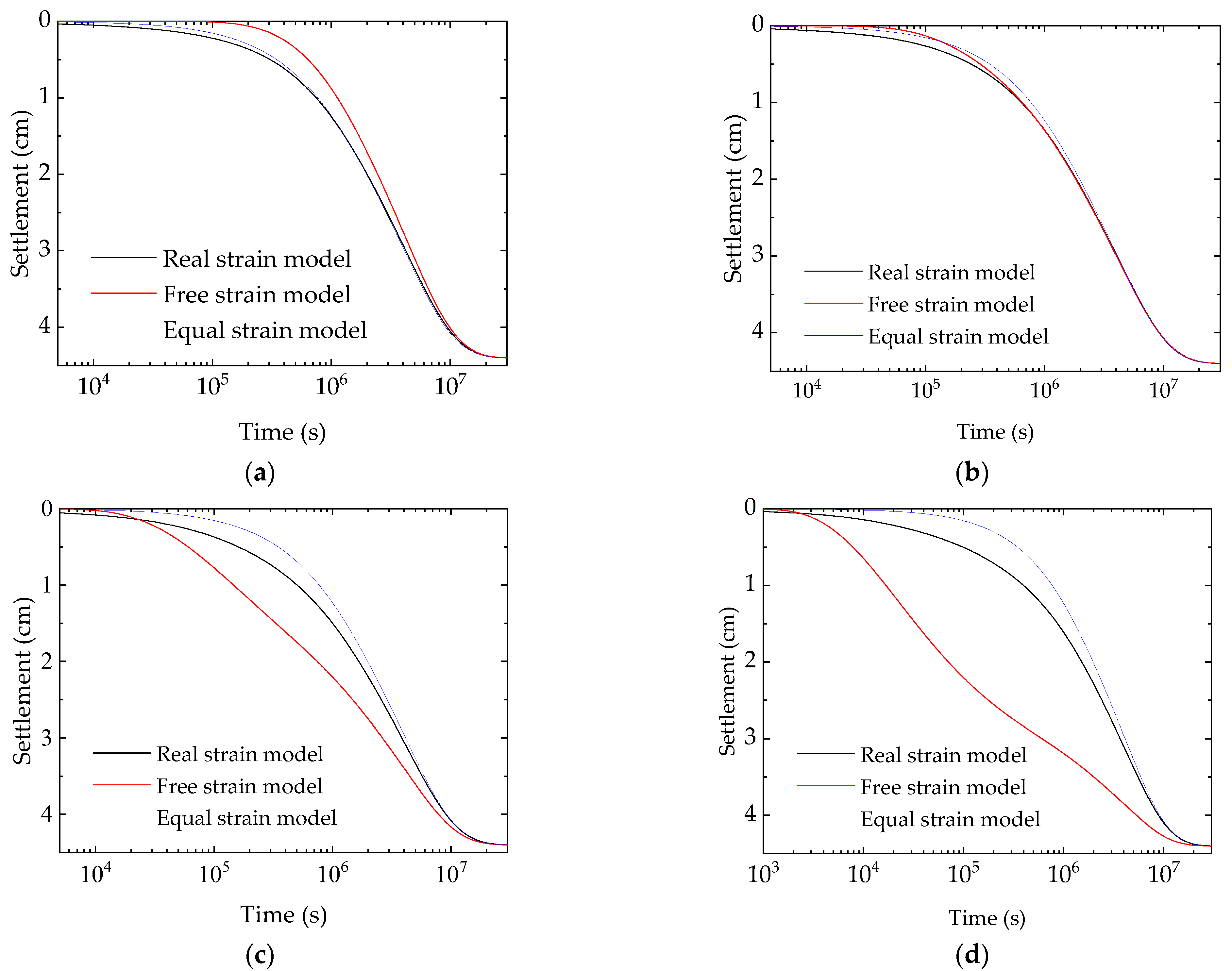
Figure 6 illustrates the deformation and spatial distribution of vertical effective stress at a certain moment (t = 2.56 × 10⁵ s) during the consolidation process of three models. Assuming equal strain produced uniform soil settlement, whereas assuming free strain produced large, uneven soil settlement, but real strain conditions produced small, uneven soil settlement, which is between these two extremes. This difference arises due to variations in the soil’s spatial distribution of the vertical effective stress for each of the three cases. The vertical effective stresses at all positions were equal in the equal strain condition, while in the free strain condition, the stresses decreased further away from the vertical drain but were constant in the vertical direction. Under real strain conditions, the stresses decreased further away from the top of the vertical drain. The relationship between the surface settlement and time in different positions of the three models is displayed in Figure 7. Settlement curves of the outer soil ((r − rw)/(re − rw) > 1/2) in the real strain model aligned well with those in the equal strain condition, whereas the settlement curves of the inner soil ((r − rw)/(re − rw) < 1/2) in the real strain model fell between the other two assumptions.
4.2. Pore Pressure
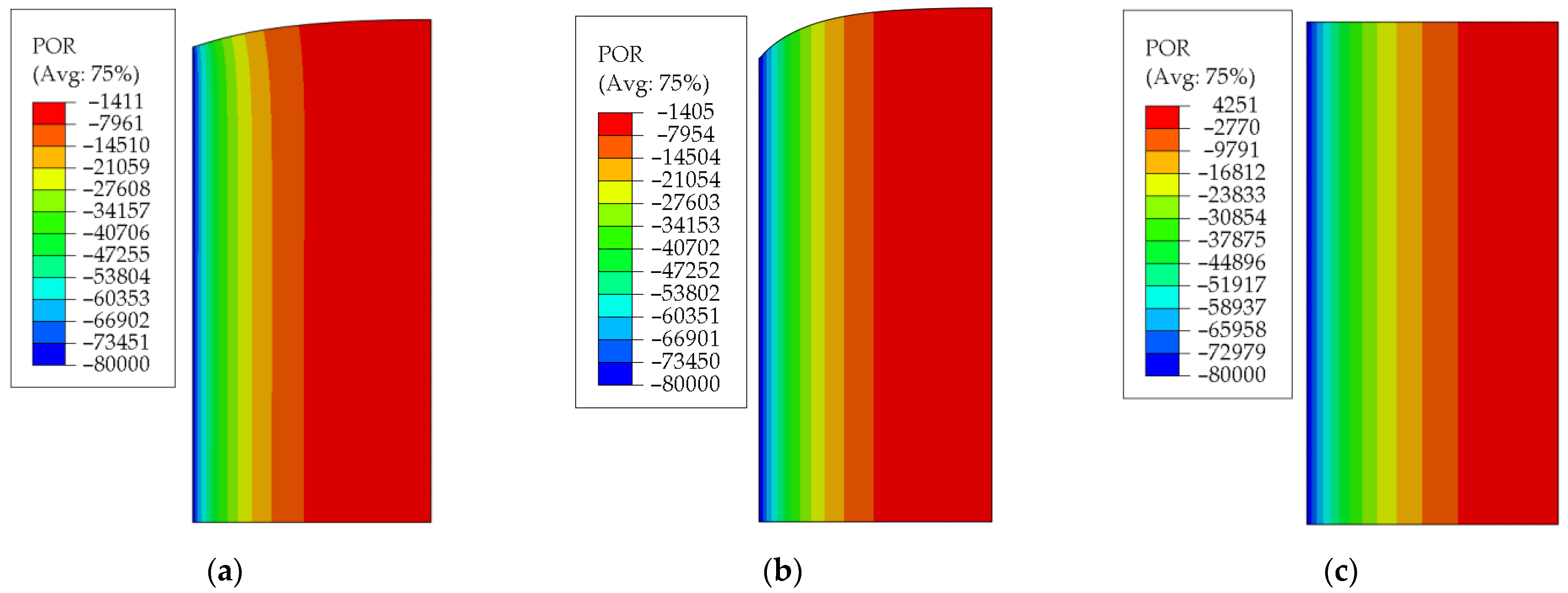
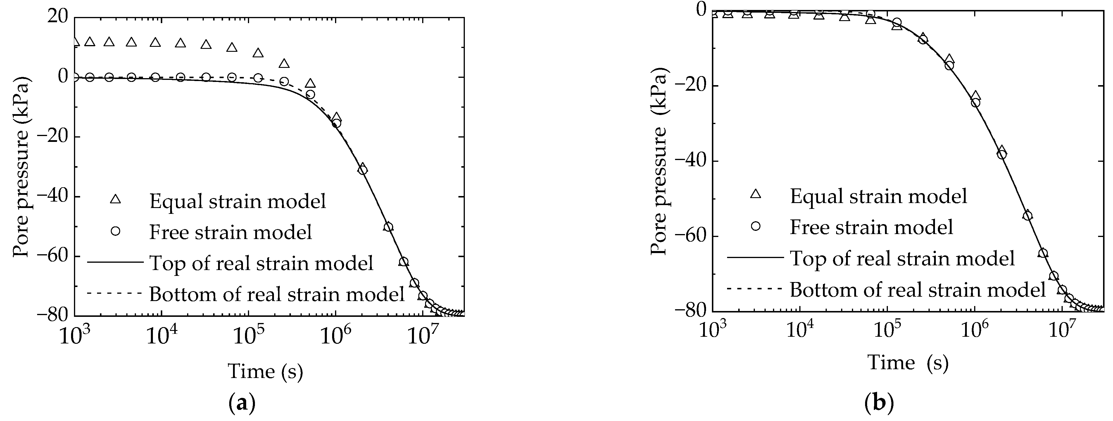
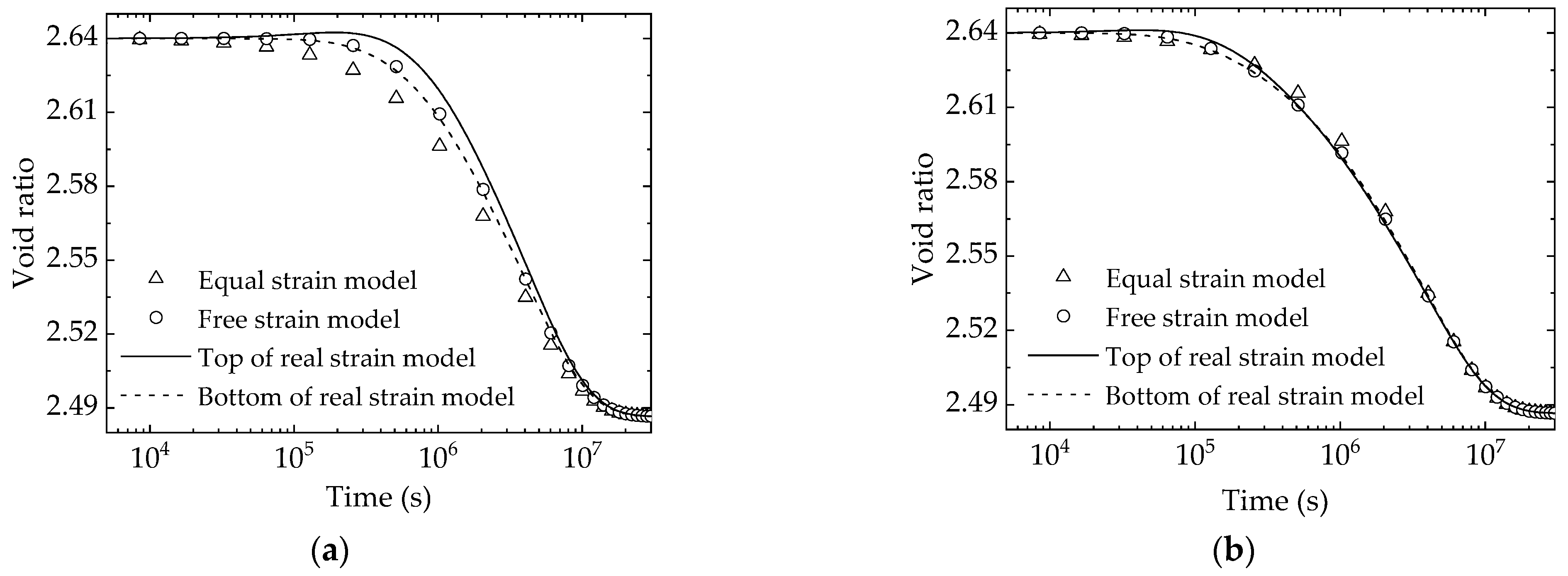
Figure 8 shows the deformation and spatial distribution of vertical effective stress at a certain moment (t = 2.56 × 10⁵ s) during the consolidation process of three models. Figure 9 illustrates the time-dependent pore pressure distribution in three different models at varying radial locations during the consolidation process. The results showed that the pore pressure estimates from the equal strain model significantly deviated from those obtained by the real strain model during the initial stage of consolidation. During early consolidation (t = 1000 s), positive pore pressure (the pore pressure is considered positive under compression) was observed in the soil at R = 1, whereas the pore pressure values declined to −22.7 kPa and −48.1 kPa at R = 1/4 and R = 1/10, respectively (Figure 9a,c,d). The cause of this deviation is attributed to the presence of a rigid foundation on the surface of the soil in the equal strain model, resulting in similar compression of the soil at the same height. Consequently, the outer soil, which drained slower, was subjected to pressure from the foundation, causing in Equation (8) to be positive and resulting in a pore water pressure increase. In contrast, the inner soil was subjected to tension from the foundation, resulting in in Equation (8) to be negative, leading to a decrease in pore water pressure. Once the consolidation time surpassed 1/10 of the total consolidation time, the pore pressure values of the equal strain model and real strain model were similar. Figure 9 also indicates that the pore pressure at the bottom of the real strain model was consistent with the free strain model. Since there was no vertical displacement at the bottom of the real strain model (boundary condition), shear deformation did not occur. As a result, the consolidation equation of the soil under the assumption of free strain was identical to that of the soil at the bottom of the real strain model. Therefore, the pore pressure calculated using the free strain assumption was the same as that at the bottom of the real strain model.
Under the real strain condition, the pore pressure of soil varied with different depths. In the early stage of consolidation, the pore pressure of the soil at the top of the inner side was higher than that at the bottom (as shown in Figure 9a), while the pore pressure of the soil at the top of the outer side was lower than that at the bottom (as shown in Figure 9c,d). As the consolidation progressed, the pore pressure at the top and bottom of the soil tended to become equal.
4.3. Void Ratio
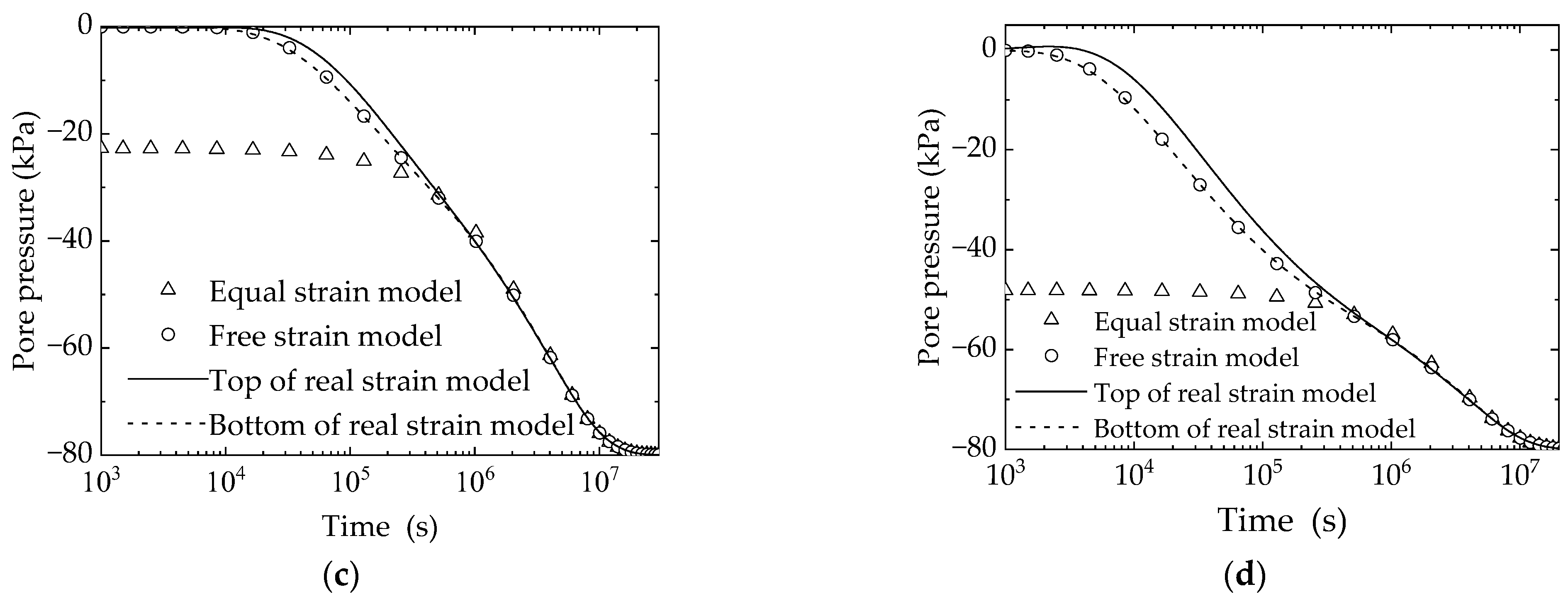
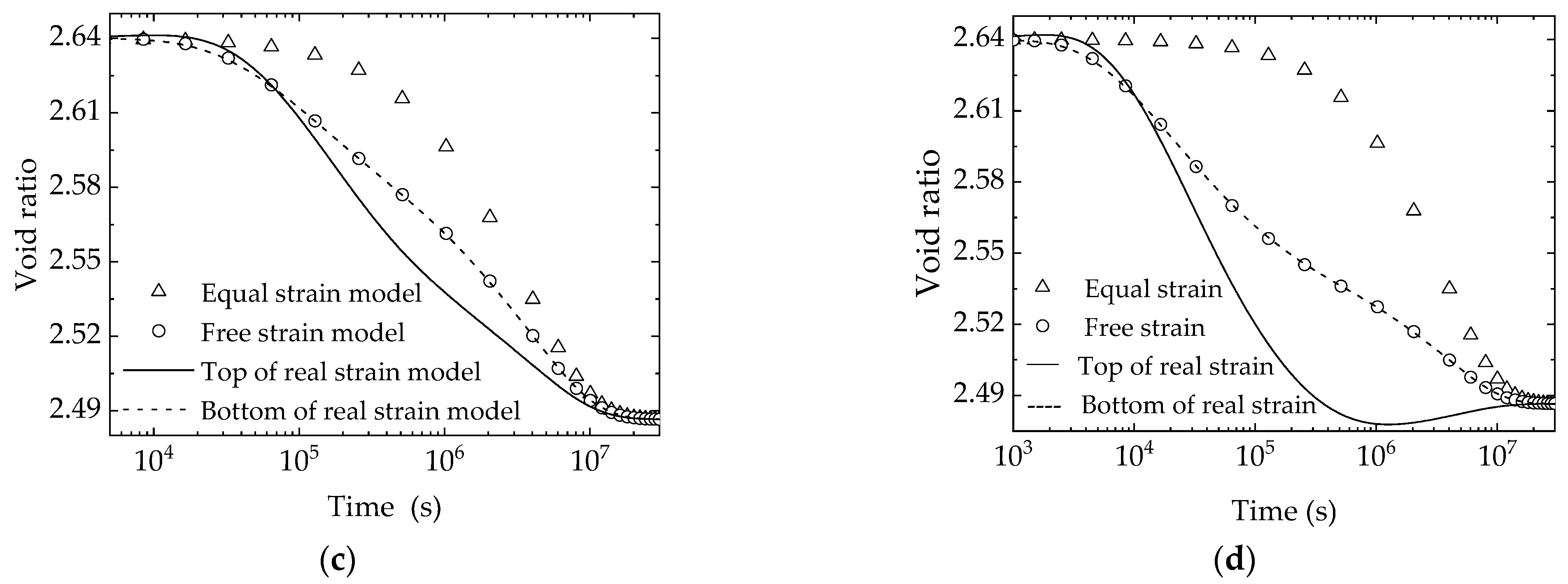
Figure 10 illustrates the relationship between the void ratio and time across different radial positions of three models. It indicates that the void ratio of the soil at the top of the real strain model initially slightly increased, followed by a subsequent decrease. The figure demonstrates that in the early stage of consolidation, the affected area of vacuum preloading was relatively small, leading to a proportional increase in the void ratio of the outer soil. As the consolidation period increased, the influenced area expanded, the tensile area developed outward, and the previously tensioned soil consolidated, causing the void ratio to decrease. Hence, the soil’s void ratio initially increased and then decreased during consolidation.
The void ratio of the soil near the top of the vertical drain (R = 1/10) experienced a sharp reduction during consolidation (as depicted in Figure 10), with the void ratio in the middle of consolidation being less than when the consolidation process was completed. This phenomenon is due to the Mandel–Cryer effect that occurred close to the vertical drain.
Cryer initially discovered this effect in a radially consolidated soil ball. Assuming that the soil ball’s surface is permeable, and a uniformly distributed load is applied to it, the pore pressure at the center of the soil ball initially rises above the applied load, then decreases. This phenomenon occurs because during the drainage process, the soil ball’s surface drains and shrinks, compressing the interior and causing the total stress of the internal soil to rise. However, the pore water of the interior soil has not yet been discharged, and there is no volume deformation. As a result, the soil skeleton cannot bear the increased stress, and the increase of total stress can only be borne by the pore water. As the consolidation time increases, the interior soil drains and consolidates, resulting in a decrease in pore pressure, and the pore pressure of the interior soil first increases and then decreases.
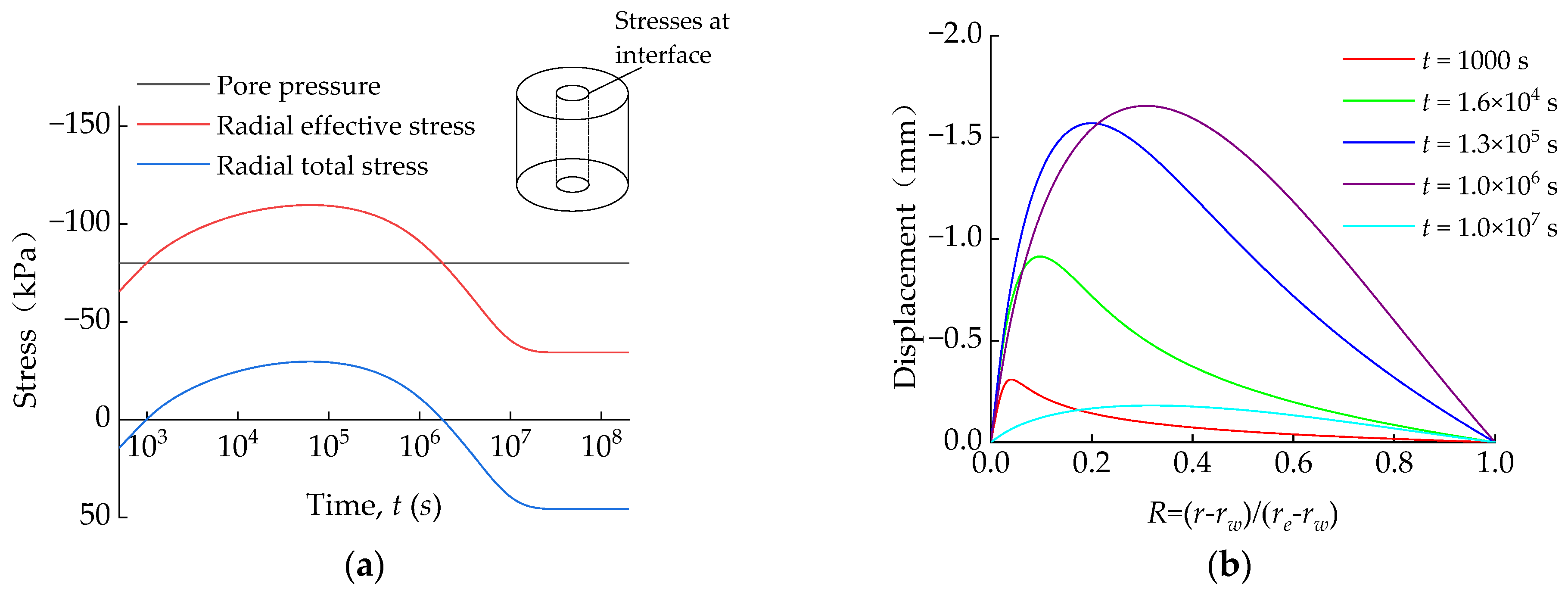
During the consolidation process of the real strain model, the outer soil underwent radial shrinkage under vacuum pressure, and the contracted shell squeezed the inside, leading to an increase in the total stress of the soil near the vertical drain. As the soil near the vertical drain is close to the negative pressure boundary, the pore pressure quickly reached −80 kPa and remained constant. Therefore, the increase of the total stress did not lead to the increase of the pore pressure, but the increase of the effective stress. Figure 11 illustrates the curves of radial effective stress of the soil at the top of the vertical drain. It was observed from the graph that within 1.3 × 10⁵ s, the radial displacement of the soil at 0 < R < 0.2 continued to increase, and the total horizontal stress of the soil at the top of the vertical drain also increased, while the pore pressure remained at −80 kPa, resulting in an increase in horizontal effective stress. Due to the Mandel–Cryer effect, the increase in effective stress during consolidation exceeded the increase caused by vacuum pressure, leading to a further reduction in the void ratio. Since there is a relationship between the permeability coefficient of soil and the void ratio, the Mandel–Cryer effect of vacuum preloading can significantly reduce the permeability coefficient of soil, which partially explains the silting phenomenon near the vertical drain during vacuum preloading. Both the equal strain assumption and the free strain assumption only study the dissipation process of pore water pressure in soil, without involving the coupling effect of soil deformation. Hence, the Mandel–Cryer effect did not occur in these assumptions.
Figure 10 demonstrates that the void ratio of soil calculated by the free strain model was consistent with the real strain model’s soil at the bottom, while the equal strain assumption can only reflect the change of the void ratio of the soil at R = 1/2. Neither assumption can accurately predict the void ratio of the soil near the top of the vertical drain (Figure 10d). The change of the void ratio reflects the change of effective stress. Many researchers have discovered relationships between the permeability coefficient, compressibility coefficient, and effective stress change [24,25]. Therefore, considering these two parameters’ changes with the average effective stress, merely applying Barron’s assumptions would introduce numerous errors.
4.4. Average Consolidation Degree
The average consolidation degree, U, of the soil is a practical engineering concept that reflects the ratio of the soil’s compression at a specific moment to its final compression amount. The average consolidation degree of soil can be expressed as:
In the equation, V represents the total volume of the soil at a particular moment during the consolidation process, V1 is the total volume at the completion of consolidation, and V0 is the total volume at the beginning of consolidation.
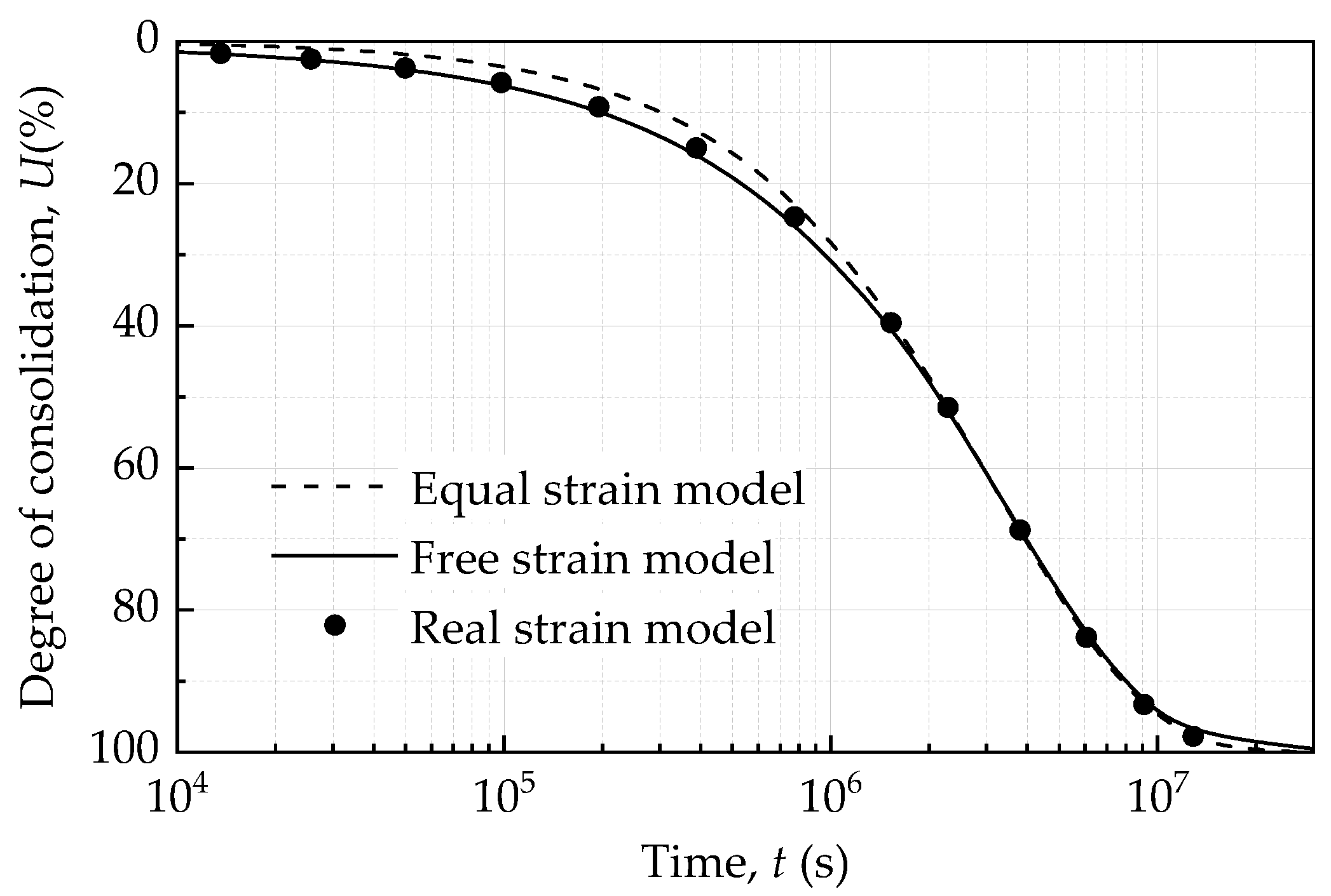
The curves of the average consolidation degree with time calculated under the assumptions of Barron and the real strain condition are shown in Figure 12. Both Barron’s assumptions can produce generally consistent results. However, the equal strain assumption tended to underestimate the average consolidation degree of the soil during the early stages of consolidation, whereas the result under the free strain assumption was closer to the real strain model.
5. Parametric Analysis for Real Strain Model
5.1. Influence of Elastic Modulus on Consolidation Efficiency
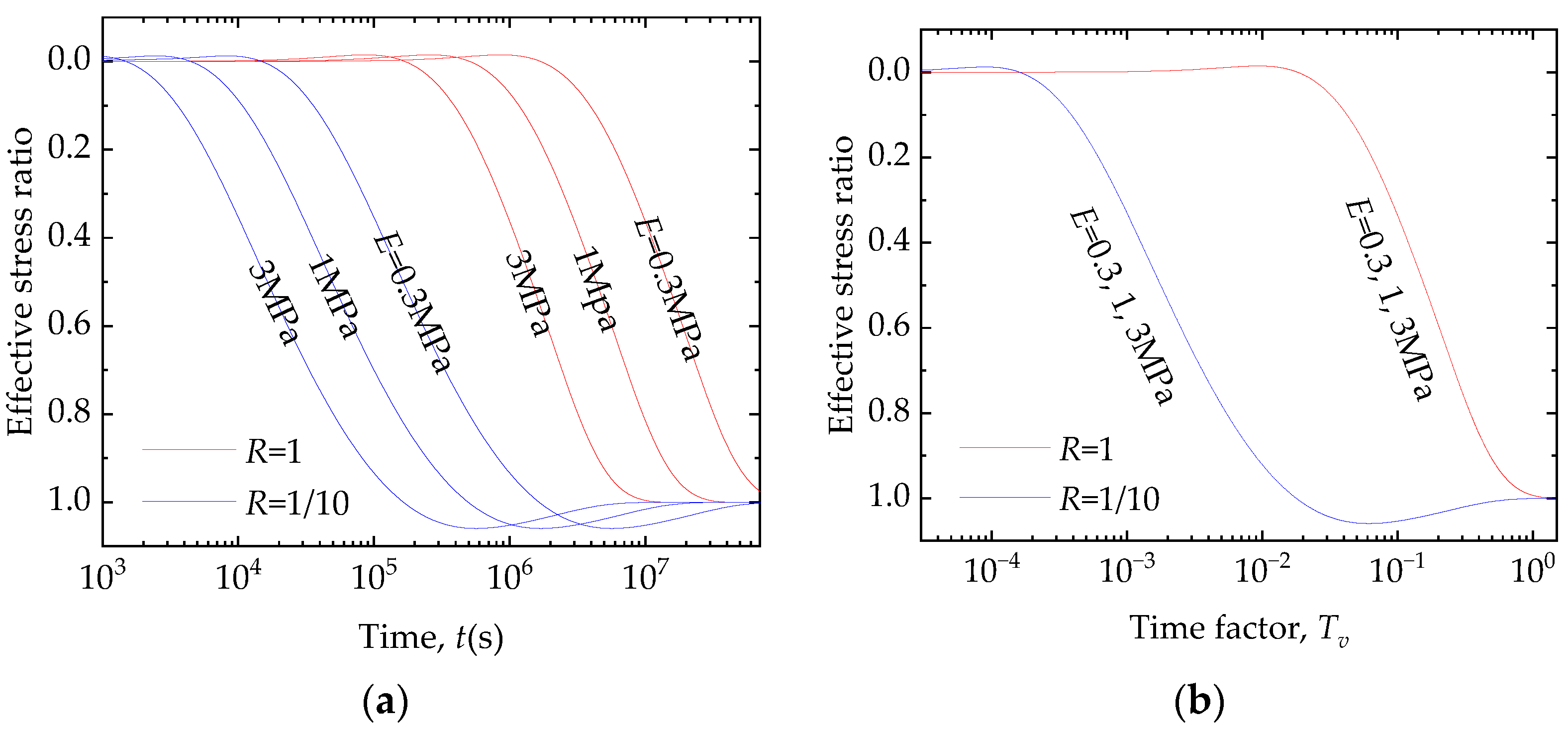
In case of linear elastic solids, the consolidation degree of a certain soil can also be expressed by its average effective stress ratio, ( is the average effective stress of the soil at a given moment, and is the average effective stress of soil after consolidation). Figure 13a illustrates the effective stress ratio of the soil at different radial positions with time under the real strain condition at varying values of elastic modulus (E = 0.3 MPa, E = 1 MPa, E = 3 MPa). Section 4.3 analyzed the variation pattern of the void ratio and found that the void ratio of soil initially increased and then decreased, causing the average effective stress ratio to drop to a negative value and then subsequently escalate. An effective stress ratio greater than 1 is attributed to the Mandel–Cryer effect, which causes the effective stress of soil during the consolidation to exceed the effective stress when the consolidation is complete.
When the elastic modulus increased from 0.3 MPa to 3 MPa, the curves of the effective stress ratio moved to the left, indicating an increase in the consolidation rate. The dimensionless time factor, , is defined as the ratio between the consolidation time and the square of the characteristic length. By modifying the abscissa from time to the time factor (as shown in Figure 13b), the relationship curves between the degree of consolidation and the time factor completely coincided. This is consistent with Terzaghi’s one-dimension consolidation law, which means the time required for soil to reach the same degree of consolidation is inversely proportional to the elastic modulus [26].
5.2. Influence of Permeability Coefficient on Consolidation Efficiency
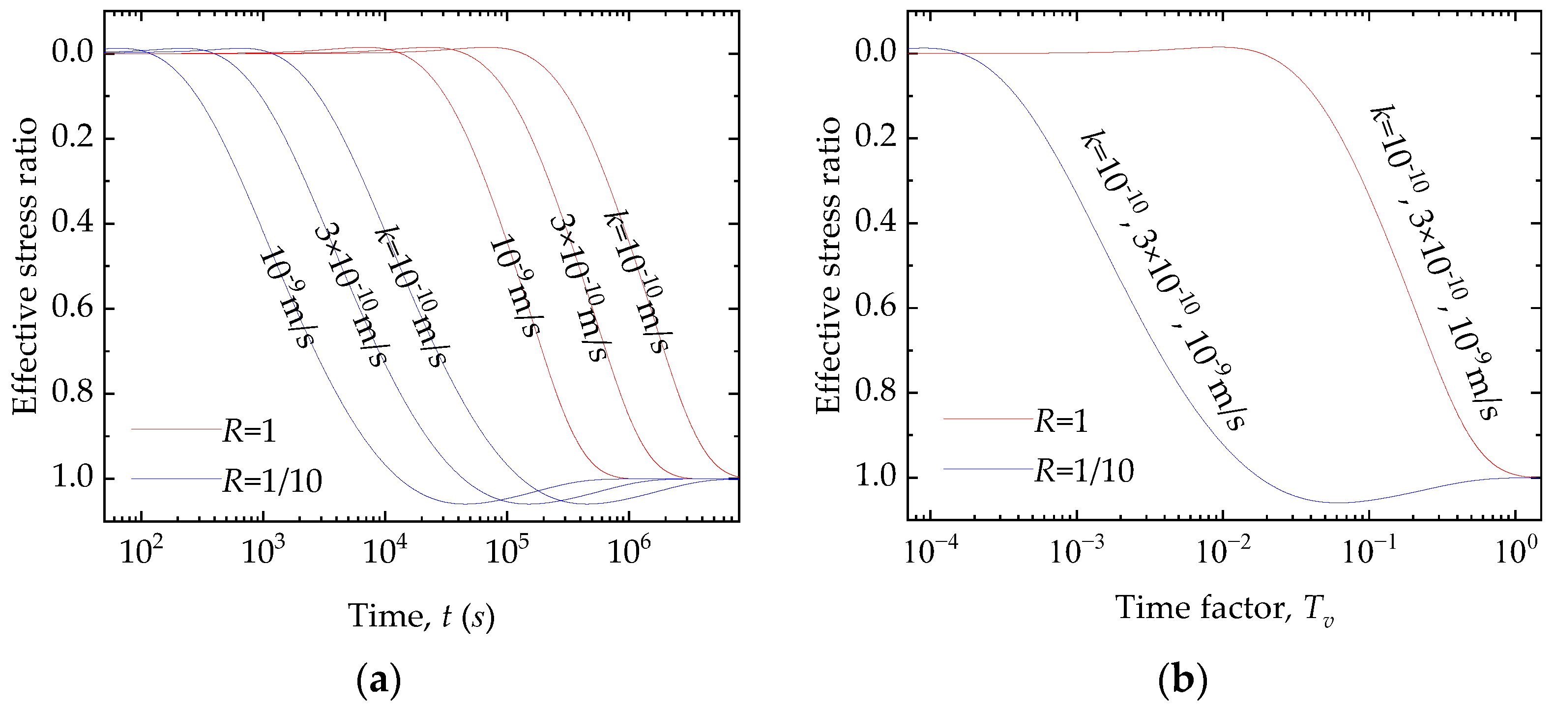
Figure 14a shows the results of the effective stress ratio of the soil at different radial positions with time under the real strain condition for three permeability coefficients: k = 1 × 10⁻¹⁰ m/s, k = 3 × 10⁻¹⁰ m/s, and k = 1 × 10⁻⁹ m/s. As the permeability coefficient increased from 1 × 10⁻¹⁰ m/s to 1 × 10⁻⁹ m/s, the degree of consolidation curves shifted left, indicating an accelerated consolidation rate. This finding aligns with Terzaghi’s theory of one-dimensional consolidation, as well. Notably, the time required for the soil to achieve the same degree of consolidation decreased as the permeability coefficient increased (as shown in Figure 14b). Furthermore, when time was expressed as a time factor instead of absolute time, the degree of the consolidation curves overlapped.
5.3. Influence of Poisson’s Ratio on Consolidation Efficiency
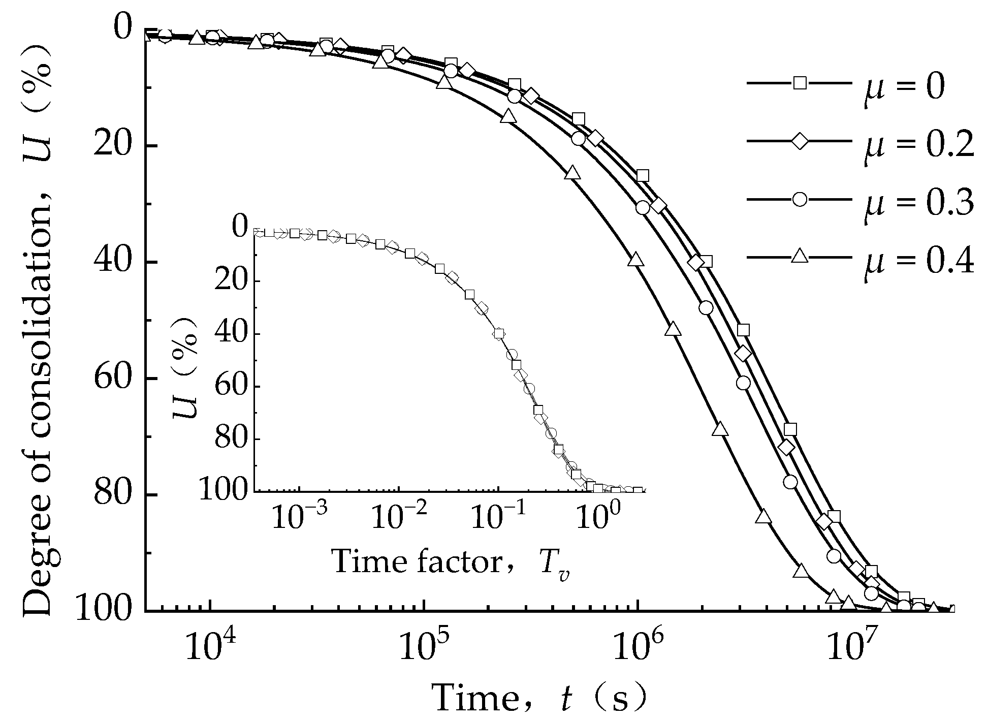
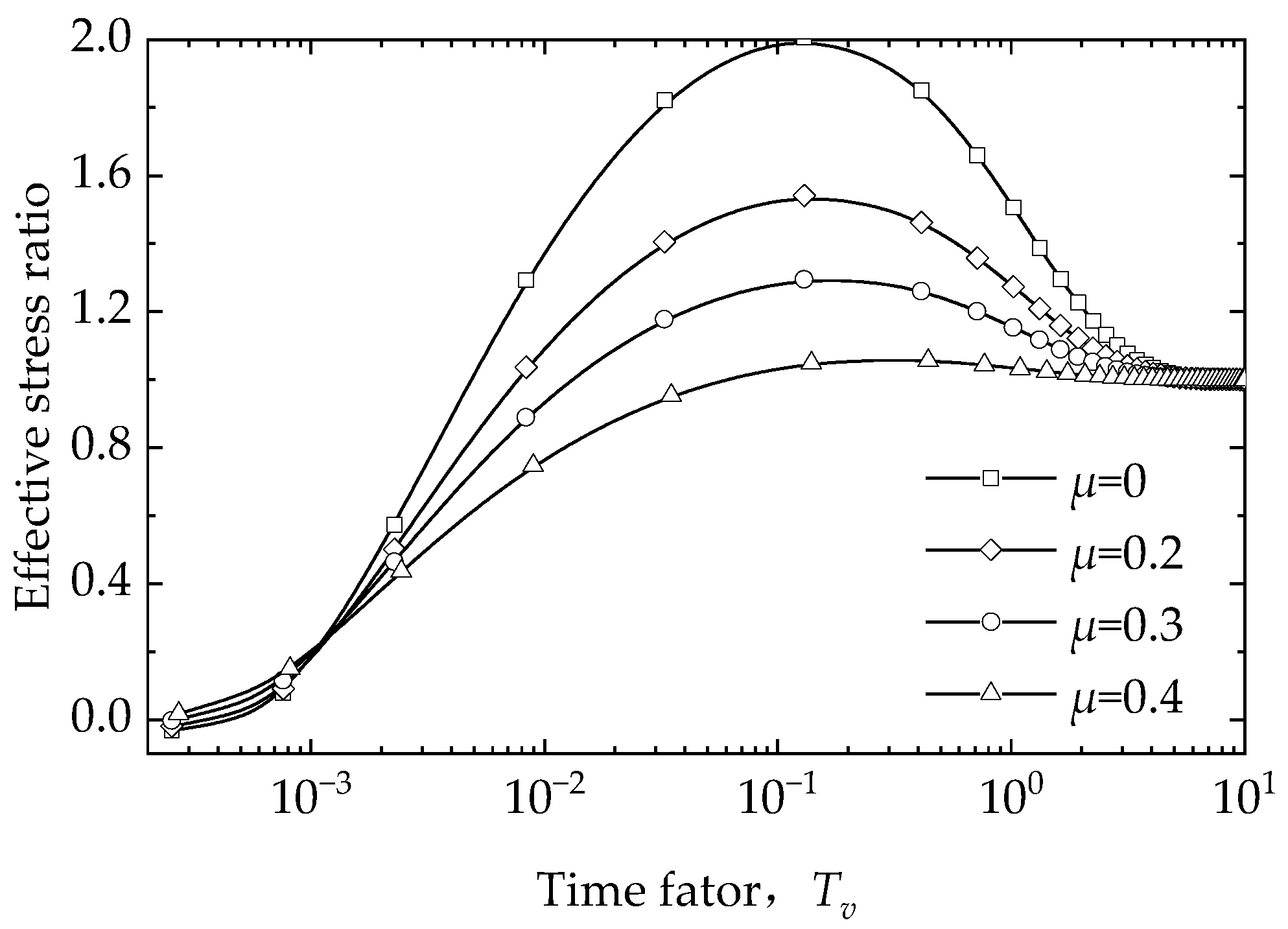
This section investigates the effect of Poisson’s ratio on the consolidation of soil during the vacuum preloading process by assigning different Poisson’s ratios to the soil, while keeping other parameters constant. The compression modulus of soil is affected by Poisson’s ratio. As observed in Figure 15, increasing Poisson’s ratio from 0 to 0.4 moved the curves of the consolidation degree to the left. This phenomenon occurs because an increase in Poisson’s ratio leads to a higher compressive modulus, and thus, a faster consolidation rate, while the elastic modulus of soil remains the same. On the other hand, Poisson’s ratio affects the Mandel–Cryer effect during consolidation. As depicted in Figure 16, under real strain conditions, a decrease in Poisson’s ratio resulted in a larger peak value of the effective stress ratio of the soil near the top of the vertical drain. This indicated that the soil in this region was denser during the consolidation process than it was upon completion of consolidation. The Mandel–Cryer effect increased with the decreasing Poisson’s ratio [27]. Hence, Poisson’s ratio exerted an influence on the effective stress ratio of soil during consolidation, significantly affecting the local consolidation degree. However, since the soil was linear elastic and had a constant permeability coefficient, the Mandel–Cryer effect would not affect the average consolidation degree. As shown in Figure 15, when the abscissa was changed to the time factor, the average consolidation curves of soil with different Poisson’s ratios completely coincided.
5.4. Influence of Drain Spacing Ratio on Consolidation Efficiency
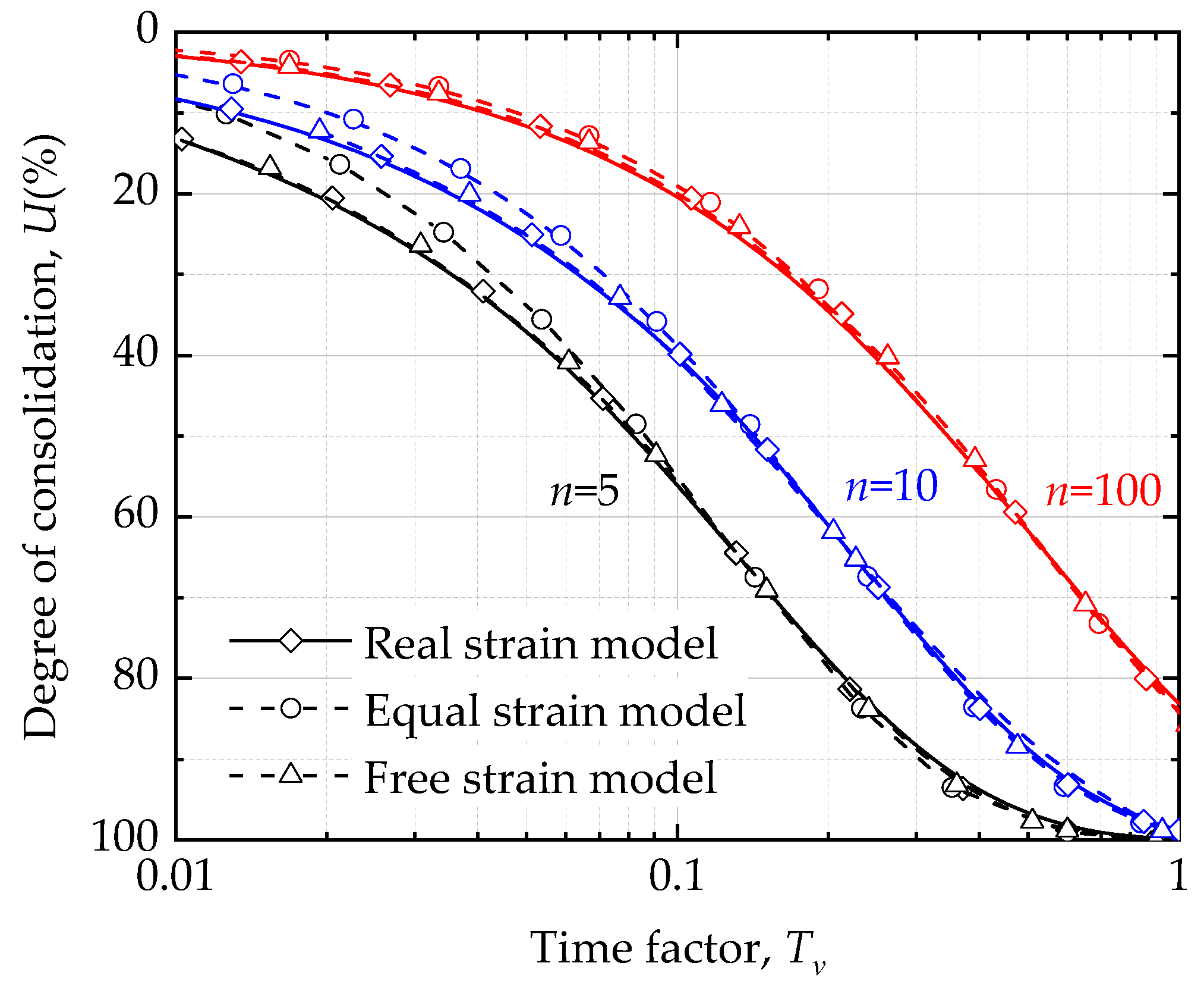
This study analyzed the influence of the drain spacing ratio (re/rw) on soil consolidation during vacuum preloading, with unchanged soil parameters and vertical drain sizes but different drain radii (re). The consolidation curves, as illustrated in Figure 17, showed that the consolidation curve of the real strain model was consistently similar to that of the free strain model, regardless of the variations in the drain spacing ratio. However, the initial degree of consolidation, obtained under the equal strain assumption, was relatively small when the drain spacing ratio was small. When the degree of consolidation exceeded 50%, the curves in all three cases tended to be consistent. Moreover, if the drain spacing ratio was sufficiently large, the results of the consolidation degree under free strain and equal strain assumptions were consistent.
6. Conclusions
By simulating the soil consolidation process during vacuum preloading under three deformation modes, including equal strain, free strain, and real strain, the following conclusions were drawn:
(1) The real strain model, a finite element model for single-drain well consolidation under vacuum preloading, was established based on strict axisymmetric-coupled flow and solid consolidation theory. Degenerating the consolidation equation yielded the Barron’s classical free strain and equal strain equations. The free strain and equal strain finite element models were obtained by applying boundary and constraint conditions to the real strain finite element model.
(2) We acquired variations in the average degree of consolidation over time for all three models. The free strain model provided the most similar degree of consolidation to the real strain model, unlike the equal strain model, which recorded a lower initial degree of consolidation when the drain spacing ratio was small.
(3) The real strain model revealed the Mandel–Cryer effect of soil near the vertical drain during the initial vacuum preloading consolidation process. This effect caused the effective stress to increase more than the effective stress generated by the vacuum pressure, leading to a greater reduction in the void ratio. This phenomenon is one of the reasons for clogging during the vacuum preloading process. However, the free strain and equal strain models could not produce this effect because they cannot describe the coupling between soil deformation and fluid flow.
(4) The parameter analysis of the real strain model showed that as Poisson’s ratio for soil decreased, the consolidation rate of soil also decreased, while the Mandel–Cryer effect of soil increased.
Author Contributions
Conceptualization, X.P. and H.Z. (Haijun Zhu); methodology, X.P. and H.Z. (Haijun Zhu); software, H.Z. (Haijun Zhu); formal analysis H.Z. (Haijun Zhu) and H.Z. (Huailin Zheng); writing—original draft preparation, H.Z. (Haijun Zhu) and X.P.; writing—reviewing and editing, X.P., H.S. and X.G. All authors have read and agreed to the published version of the manuscript.
Funding
This research was funded by the National Natural Science Foundation of China (51978621, U2006225), the Natural Science Foundation of Zhejiang Province (LTZ21E080001), and the European Union’s Horizon 2020 Framework Programme, Marie Sklodowska-Curie Individual Fellowships, under grant agreement: 101025312.
Data Availability Statement
Not applicable.
Acknowledgments
This project was supported by the Engineering Research Center of the Ministry of Education for Renewable Energy Infrastructure Construction Technology.
Conflicts of Interest
The authors declare no conflict of interest.
References
- Xie, L.; Liang, Z.; Feng, G.; Li, Y.; Wu, T. Improved Analytical Solution for Air–Boosted Vacuum Consolidation of Saturated Soil Using Eigenfunction Expansion Method. Symmetry 2022, 14, 1757. [Google Scholar] [CrossRef]
- Barron, R.A. Consolidation of Fine-Grained Soils by Drain Wells by Drain Wells. Trans. Am. Soc. Civ. Eng. 1948, 113, 718–742. [Google Scholar] [CrossRef]
- Richart, F. A Review of the Theories for Sand Drains. J. Soil Mech. Found. Div. 1957, 83, 1–38. [Google Scholar] [CrossRef]
- Yoshikuni, H.; Nakanodo, H. Consolidation of Soils by Vertical Drain Wells with Finite Permeability. Soils Found. 1974, 14, 35–46. [Google Scholar] [CrossRef] [PubMed]
- Kok, L.; Jamiolkowski, M.; Hansbo, S. Consolidation by vertical drains. Geotechnique 1981, 31, 45–66. [Google Scholar]
- Pyrah, I.; Hird, C.; Russel, D. Finite element modeling of vertical drains beneath embankments on soft ground. Geotechnique 1992, 42, 499–511. [Google Scholar]
- Indraratna, B.; Balasubramaniam, A.; Sivaneswaran, N. Analysis of settlement and lateral deformation of soft clay foundation beneath two full-scale embankments. Int. J. Numer. Anal. Methods Geomech. 1997, 21, 599–618. [Google Scholar] [CrossRef]
- Indraratna, B.; Rujikiatkamjorn, C.; Sathananthan, I. Analytical and numerical solutions for a single vertical drain including the effects of vacuum preloading. Fac. Eng. Pap. 2005, 42, 994–1014. [Google Scholar] [CrossRef]
- Chen, X.D.; Zhao, W.B. Equivalent analyzing method of plane strain of drain pile ground considering well resistance and smearing. Rock Soil Mech. 2005, 26, 567–571. [Google Scholar]
- Li, Z.; Lei, G.; Fu, C. Free-strain solutions for two-dimensional consolidation with a sand-wall drain. Rock Soil Mech. 2016, 37, 1613–1622. [Google Scholar]
- Biot, M. General Theory of Three-Dimensional Consolidation. J. Appl. Phys. 1941, 12, 155–164. [Google Scholar] [CrossRef]
- Mandel, J. Consolidation des sols. Comptes Rendus Hebd. Des Séances De L’académie Des Sci. Paris 1951, 3, 287–299. [Google Scholar]
- Cryer, C. A comparison of the three-dimensional theories of Biot and Terzaghi. Q. J. Mech. Appl. Math. 1963, 16, 401–412. [Google Scholar] [CrossRef]
- Gibson, R.E.; Knight, K.; Taylor, P.W. A Critical Experiment to Examine Theories of Three-dimensional Consolidation. Proc. Eur. Conf. Soil Mech. Found. Eng. 1963, 1, 69–76. [Google Scholar]
- Smith, M. ABAQUS/Standard User’s Manual; Version 6.9; Dassault Systèmes Simulia Corp: Providence, RI, USA, 2009. [Google Scholar]
- Indraratna, B. Recent advances in the application of vertical drains and vacuum preloading in soft soil stabilisation. Aust. Geomech. J. 2010, 45, 1–43. [Google Scholar]
- Sandhu, R.; Wilson, E. Finite-Element Analysis of Seepage in Elastic Media. J. Eng. Mech. Div. 1969, 95, 641–652. [Google Scholar] [CrossRef]
- Yuebao, D.; Xie, K.H.; Li, C.-x. Finite element analysis of Biot’s consolidation with non-Darcian flow. Yantu Gongcheng Xuebao/Chin. J. Geotech. Eng. 2012, 34, 2058–2065. [Google Scholar]
- Yuebao, D.; Xie, K.H.; Wang, K. Mesh sensitivity study for the consolidation of composite ground with granular column by FEM. J. Hunan Univ. 2012, 39, 12–17. [Google Scholar]
- Li, F.; Xie, K.; Yuebao, D. Analytical solution for consolidation by vertical drains with exponential flow under vacuum preloading. Zhongnan Daxue Xuebao (Ziran Kexue Ban)/J. Cent. South Univ. (Sci. Technol.) 2015, 46, 1075–1081. [Google Scholar]
- Deng, Y.-b.; Liu, G.-b.; Zheng, R.-y.; Xie, K.-h. Finite Element Analysis of Biot’s Consolidation with a Coupled Nonlinear Flow Model. Math. Probl. Eng. 2016, 2016, 1–13. [Google Scholar] [CrossRef] [Green Version]
- Chen, P.S.; Fang, Y.G.; Mo, H.; Zhang, G.X.; Dong, Z.L. Analysis of 3D FEM for soft foundation improved by vacuum preloading. Chin. J. Geotech. Eng. 2009, 31, 564–570. [Google Scholar]
- Vermeer, P.; Verruijt, A. An Accuracy Condition for Consolidation by Finite Elements. Int. J. Numer. Anal. Methods Geomech. 1981, 5, 1–14. [Google Scholar] [CrossRef]
- Roscoe, K.H. On yielding of soils. Geotechnique 1958, 8, 22–53. [Google Scholar] [CrossRef]
- Huang, Y.; Drnevich, V. Permeability and Consolidation of Normally Consolidated Soils. J. Geotech. Eng. Div. 1982, 108, 835–850. [Google Scholar]
- Terzaghi, K. Theoretical Soil Mechanics; John Wiley & Sons, Inc.: New York, NY, USA, 1943. [Google Scholar]
- Cheng, A.; Abousleiman, Y.; Detournay, E.; Cui, L.; Roegiers, J.C. Mandel’s problem revisited. Geotechnique 1996, 46, 187–195. [Google Scholar]
Figure 1.
Diagram of the soil foundation with vertical drain: (a) analysis scheme (b) unit body.

Figure 2.
Axisymmetric mesh for vertical drain foundation.

Figure 3.
Effect of grid size on FEM analysis: (a) different vertical grid size and (b) different horizontal grid size.
Figure 3.
Effect of grid size on FEM analysis: (a) different vertical grid size and (b) different horizontal grid size.

Figure 4.
Consolidation degree curves of equal strain mode.

Figure 5.
Pore pressure curves of free strain mode.

Figure 6.
Vertical stress cloud on the deformed shape of three cases (t = 2.56 × 10⁵ s, Unit: Pa): (a) real strain condition, (b) free strain assumption, and (c) equal strain assumption.
Figure 6.
Vertical stress cloud on the deformed shape of three cases (t = 2.56 × 10⁵ s, Unit: Pa): (a) real strain condition, (b) free strain assumption, and (c) equal strain assumption.

Figure 7.
Surface settlement curves of the soil in different radial positions: (a) R = (r − rw)/(re − rw) = 1, (b) R = (r − rw)/(re − rw) = 1/2, (c) R = (r − rw)/(re − rw) = 1/4, and (d) R = (r − rw)/(re − rw) = 1/10.
Figure 7.
Surface settlement curves of the soil in different radial positions: (a) R = (r − rw)/(re − rw) = 1, (b) R = (r − rw)/(re − rw) = 1/2, (c) R = (r − rw)/(re − rw) = 1/4, and (d) R = (r − rw)/(re − rw) = 1/10.

Figure 8.
Pore pressure cloud on the deformed shape of three cases (t = 2.56 × 10⁵ s, Unit: Pa): (a) real strain condition, (b) free strain assumption, and (c) equal strain assumption.
Figure 8.
Pore pressure cloud on the deformed shape of three cases (t = 2.56 × 10⁵ s, Unit: Pa): (a) real strain condition, (b) free strain assumption, and (c) equal strain assumption.

Figure 9.
Pore pressure curves of soil in different radial positions: (a) R = (r − rw)/(re − rw) = 1, (b) R = (r − rw)/(re − rw) = 1/2, (c) R = (r − rw)/(re − rw) = 1/4, and (d) R = (r − rw)/(re − rw) = 1/10.
Figure 9.
Pore pressure curves of soil in different radial positions: (a) R = (r − rw)/(re − rw) = 1, (b) R = (r − rw)/(re − rw) = 1/2, (c) R = (r − rw)/(re − rw) = 1/4, and (d) R = (r − rw)/(re − rw) = 1/10.


Figure 10.
Void ratio curves of soil in different radial positions: (a) R = (r − rw)/(re − rw) = 1, (b) R = (r − rw)/(re − rw) = 1/2, (c) R = (r − rw)/(re − rw) = 1/4, and (d) R = (r − rw)/(re − rw) = 1/10.
Figure 10.
Void ratio curves of soil in different radial positions: (a) R = (r − rw)/(re − rw) = 1, (b) R = (r − rw)/(re − rw) = 1/2, (c) R = (r − rw)/(re − rw) = 1/4, and (d) R = (r − rw)/(re − rw) = 1/10.


Figure 11.
The mechanism of the Mandel–Cryer effect: (a) stresses at the interface and (b) radial displacement of soil at the interface.
Figure 11.
The mechanism of the Mandel–Cryer effect: (a) stresses at the interface and (b) radial displacement of soil at the interface.

Figure 12.
Consolidation degree curve of three models.

Figure 13.
Influence of elastic modulus on the effective stress ratio: (a) the relationship between the effective stress ratio and time and (b) the relationship between the effective stress ratio and the time factor.
Figure 13.
Influence of elastic modulus on the effective stress ratio: (a) the relationship between the effective stress ratio and time and (b) the relationship between the effective stress ratio and the time factor.

Figure 14.
Influence of the permeability coefficient on the effective stress ratio: (a) the relationship between the effective stress ratio and time and (b) the relationship between the effective stress ratio and the time factor.
Figure 14.
Influence of the permeability coefficient on the effective stress ratio: (a) the relationship between the effective stress ratio and time and (b) the relationship between the effective stress ratio and the time factor.

Figure 15.
Influence of Poisson’s ratio on the effective stress ratio.

Figure 16.
Effective stress curves under different Poisson’s ratios.

Figure 17.
Influence of the drain spacing ratio on the consolidation degree.


Table 1.
Physical properties of Wenzhou clay.
| Specific Gravity Gs | Density ρ0 (g/cm3) | Liquid Limit ωL (%) | Plastic Limit ωP (%) | Clay Content CF (%) | Silt Content SF (%) |
|---|---|---|---|---|---|
| 2.75 | 1.48 | 64 | 31 | 55 | 41 |
Disclaimer/Publisher’s Note: The statements, opinions and data contained in all publications are solely those of the individual author(s) and contributor(s) and not of MDPI and/or the editor(s). MDPI and/or the editor(s) disclaim responsibility for any injury to people or property resulting from any ideas, methods, instructions or products referred to in the content. |
© 2023 by the authors. Licensee MDPI, Basel, Switzerland. This article is an open access article distributed under the terms and conditions of the Creative Commons Attribution (CC BY) license (https://creativecommons.org/licenses/by/4.0/).
Share and Cite
MDPI and ACS Style
Pan, X.; Zhu, H.; Zheng, H.; Sun, H.; Geng, X. Analysis of Consolidation by Vertical Drain with Vacuum Preloading Based on Axisymmetric Biot’s Consolidation Theory. Symmetry 2023, 15, 1245. https://doi.org/10.3390/sym15061245
AMA Style
Pan X, Zhu H, Zheng H, Sun H, Geng X. Analysis of Consolidation by Vertical Drain with Vacuum Preloading Based on Axisymmetric Biot’s Consolidation Theory. Symmetry. 2023; 15(6):1245. https://doi.org/10.3390/sym15061245
Chicago/Turabian StylePan, Xiaodong, Haijun Zhu, Huailin Zheng, Honglei Sun, and Xueyu Geng. 2023. "Analysis of Consolidation by Vertical Drain with Vacuum Preloading Based on Axisymmetric Biot’s Consolidation Theory" Symmetry 15, no. 6: 1245. https://doi.org/10.3390/sym15061245
Note that from the first issue of 2016, this journal uses article numbers instead of page numbers. See further details here.