
Ray Tracing Simulation of X-ray Microdiffraction Beamline on the Inverse Compton Source


1
P.N. Lebedev Physical Institute of the Russian Academy of Sciences, 53 Leninsky Prospekt, 119991 Moscow, Russia
2
Skobeltsyn Institute of Nuclear Physics, Lomonosov Moscow State University, 1 Leninskie Gory, 119234 Moscow, Russia
*
Author to whom correspondence should be addressed.
Symmetry 2023, 15(5), 1068; https://doi.org/10.3390/sym15051068
Submission received: 17 April 2023
/
Revised: 5 May 2023
/
Accepted: 9 May 2023
/
Published: 11 May 2023
(This article belongs to the Special Issue Selected Papers on Lasers, Accelerators, and Optics to Celebrate the 100th Anniversary of the Birth of N.G. Basov)
Abstract
:This paper deals with the simulation of output beam parameters of the inverse Compton X-ray Source (ICS). The simulation takes into account the main parameters of the laser and electron beams, such as their pulse shapes, polarization properties as well as the angular and energy dispersion of the electrons. The layout of the presented ICS and X-ray optical beamline is dedicated to X-ray micro-diffraction studies. To maintain the axial symmetry of output X-ray beams at different photon energies, the beamline monochromator is based on a single crystal installed in the Borrmann transparency condition.
PACS:
07.85.Fv; 13.60.Fz; 41.75.Ht; 41.50.+h; 61.10.-i1. Introduction
The technological development of laser and accelerator systems has enabled advanced X-ray sources to be created. In addition to the new generation of synchrotron light facilities and free electron lasers, there exist projects involving the design and construction of novel X-ray sources based on inverse Compton (Thomson) scattering [1,2,3,4,5,6]. An inverse Compton source (ICS) is capable of providing the high spectral brightness X-ray beam needed for the extension of many important applications beyond the common X-ray tube experiments [7,8,9,10]. Among them are: medical sciences and healthcare, security systems, criminalistics and forensics, art sciences and cultural heritage, industrial and construction radiography, and material science and nanotechnology.
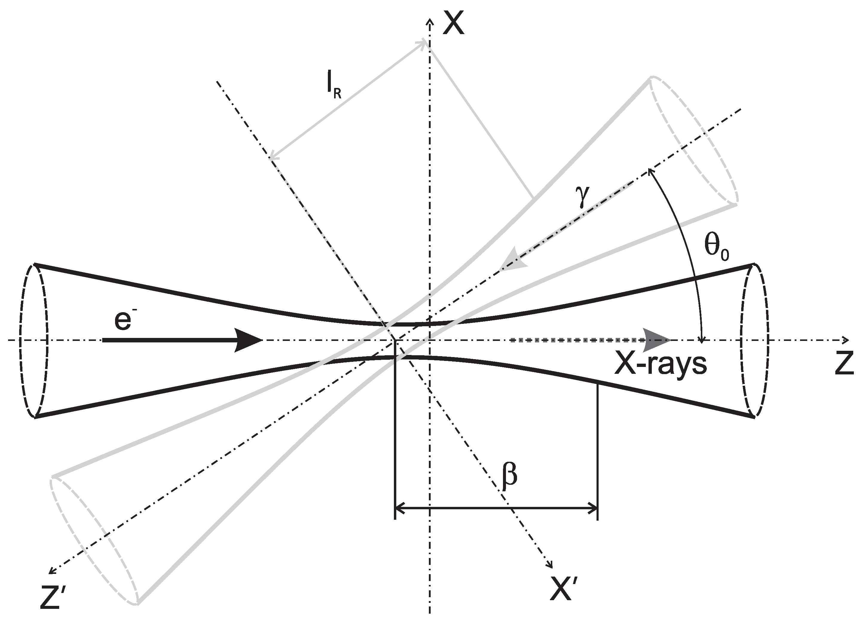
An ICS generates X-ray radiation through the inverse Compton (Thomson) scattering of laser radiation with relativistic electrons (see Figure 1). The properties of the ICS X-ray beam are similar to those of the undulator radiation [7,11], while the electron beam energy is low enough for the compact design of ICS in the framework of local laboratories and universities.
In contrast to large X-ray source facilities, the ICS can be designed to perform a specific research project or task with the best balance between cost and efficiency. Therefore, of particular importance is the accurate calculation and simulation of the spatial and temporal parameters of the output radiation produced by ICS. This evaluation of the X-ray source should include both the Thomson scattering process and output X-ray beam formation optics.
The goal of this work is to present analytical and numerical models and methods that can be used for the design and simulation of the ICS with the example of a dedicated installation for X-ray micro-diffraction experiments.
2. Theoretical Basis of ICS Simulation
For the description of the Thomson scattering process, we will use the methods and approaches mentioned in [9,12]. Note that in our case the parameters of the laser–electron interaction allow us to neglect the effects of quantum electrodynamics. The interaction of the photons and electrons is treated hereby as classical (Thomson) scattering. This process is characterized by the well-known Thomson cross-section 6.65 that does not depend on the energy, momentum and polarization of photons and electrons [13,14,15,16]. Then, all principle parameters of the generated X-ray photons such as the photon flux, spectral brilliance, and polarization of the X-ray radiation can be calculated with the help of the so called spatial matrix density function (for more details, see [12]).
A scheme of the photon–electron beam interaction is shown in Figure 1. We consider the incident photons to be monoenergetic and unidirectional. We assume also that the phase space densities of the electrons and photons are described by Gaussian functions. Then, the final expression for the matrix of the X-ray photon flux into the frequency interval and into an element of solid angle (spatial matrix density function) can be written through the integration [12]:
where and are the numbers of electrons and photons in each electron bunch or laser pulse, respectively, is the velocity of the electron divided by the velocity of light c, is the matrix of differential cross-sections for the scattering of photons by electrons, and are the semi-widths of the angular spread of electron momentums and in the x and y directions, respectively, is the effective cross-section of the interacting beams and G is the geometric factor:
where is the temporal delay of the laser pulse relative to the electron bunch, and are semi-lengths of the electron bunch and laser pulse, respectively, and are the radii of the electron beam in the x and y directions, respectively, is the radius of the laser beam. The vector shows the coordinates of the laser beam direction and is inclined to the coordinates by the collision angle in the plane (see Figure 1) and is the distance between the waists of the electron and the laser beams.
The expression for the matrix of the spectral brilliance for the ICS radiation in the direction and at the frequency has the following form [12]:
where is the position of an observer, is a small frequency interval usually assumed to be 0.1% of the radiated frequency .
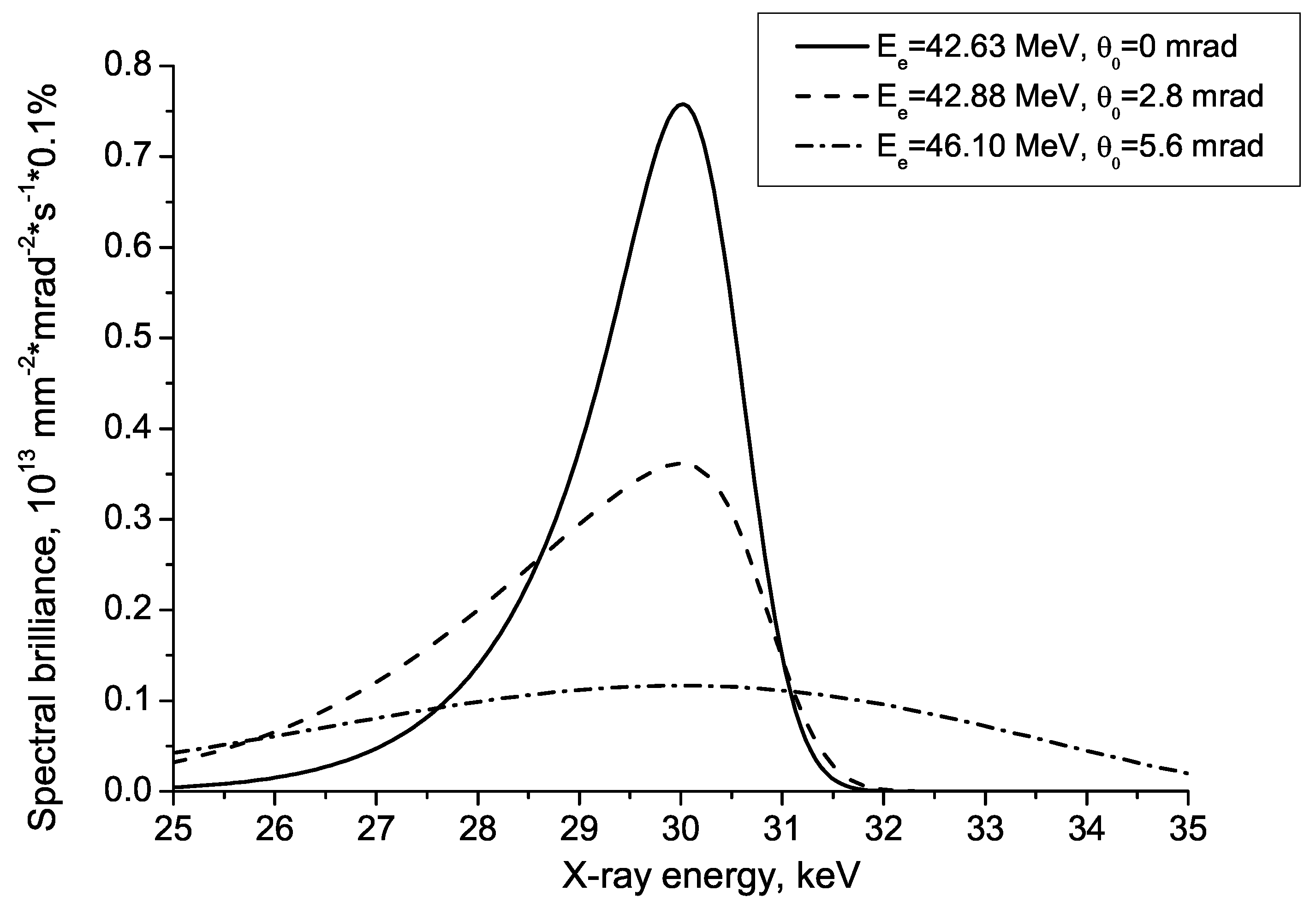
As an example, Figure 2 shows the results of the calculation of the spectral brilliance using the Formulas (1)–(3) as a function of the X-ray photon energy for three observational angles.
Figure 2.
Calculated spectral brilliance of the ICS radiation near the laser-electron interaction point as a function of the radiated photon energy for three different observational angles : 1- 0 mrad, 2- 2.8 mrad, 3- 5.6 mrad. The parameters of the electron beam and laser pulse are specified in Table 1.


Table 1.
The parameters of laser and electron beams in the point of interaction.
| Parameter | Value |
|---|---|
| Electron bunch | |
| Electron energy | 45 MeV |
| Bunch charge | 1 nC |
| Energy spread of the electrons | 1% |
| Electron beam emittance | 5 mm·mrad |
| Beta function | 10 mm |
| Electron bunch semi-length | 4 mm |
| Laser pulse | |
| Laser wavelength | 1.06 m |
| Laser pulse energy | 10 mJ |
| Laser pulse repetition frequency (in optical cavity) | 80 MHz |
| Laser pulse semi-length | 4 mm |
| Rayleigh length | 6.8 m |
| Laser-electron collision angle | 2 |
3. X-ray Beamline Design and Simulation
The ICS, as an advanced X-ray source, provides high-intensity beams needed for various fields of fundamental and applied research.
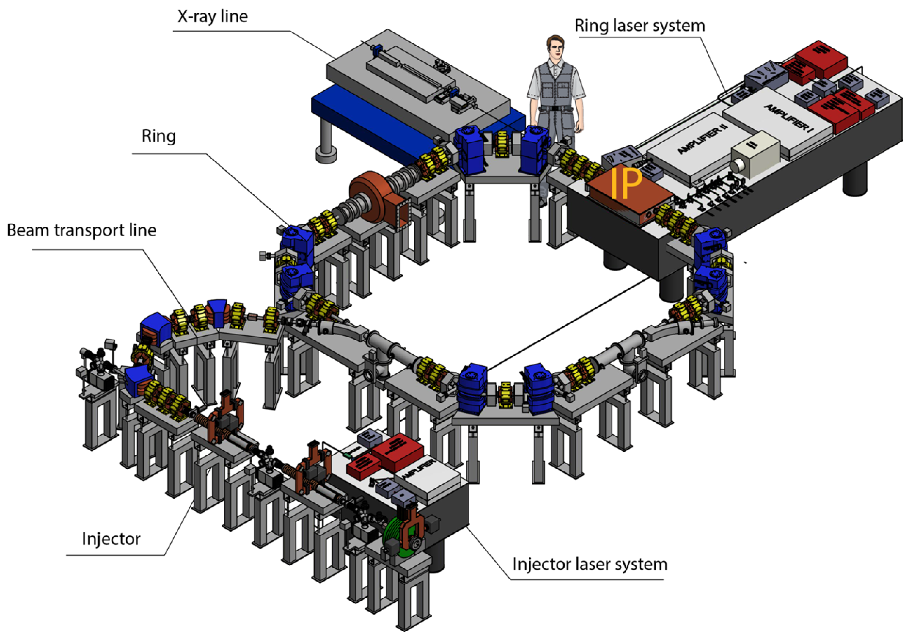
In this paper, we present the design and simulation of the ICS beamline with the example of an X-ray source dedicated to the micro-beam X-ray diffraction experiments, which are of special interest in solid state physics, diamond high-pressure cell measurements, X-ray structural analysis, and so on. The basic configuration of the ICS is chosen to be a 50-MeV storage ring developed as part of the LEXG project (see Figure 3) [12,17]. To achieve the technical specification for the beam size and monochromaticity, the corresponding beamline includes a crystal monochromator and a focusing X-ray optical system.
The numerical simulation of the X-ray optical system was carried out with SHADOW software [18]. This software is one of the popular program codes for the numerical simulation of synchrotron beamlines and X-rays optical systems. It is based on a modified algorithm of ray tracing that computes not only the ray vectors but also takes into account their phase parameters (phase ray tracing) [19]. The SHADOW code comprises software tools needed for the simulation of the most important elements of synchrotron radiation beamlines, such as crystal monochromators, grazing incidence mirrors, slit sets, gratings, etc. As an open source code, SHADOW facilitates easy extensions to new types of X-ray sources, optical elements, and beam propagators, which were unknown at the time of the original software writing. It can be argued that the SHADOW software package, in effect, has been a worldwide standard in the design and simulation of X-ray optical beamlines for more than 30 years.
We used SHADOW version 3.0 along with SHADOWVUI 1.12 graphical user interface [20]. The Laue monochromator was simulated with the XCRYSTAL 1.3 code, which is a part of the XOP 2.4 software package [21].
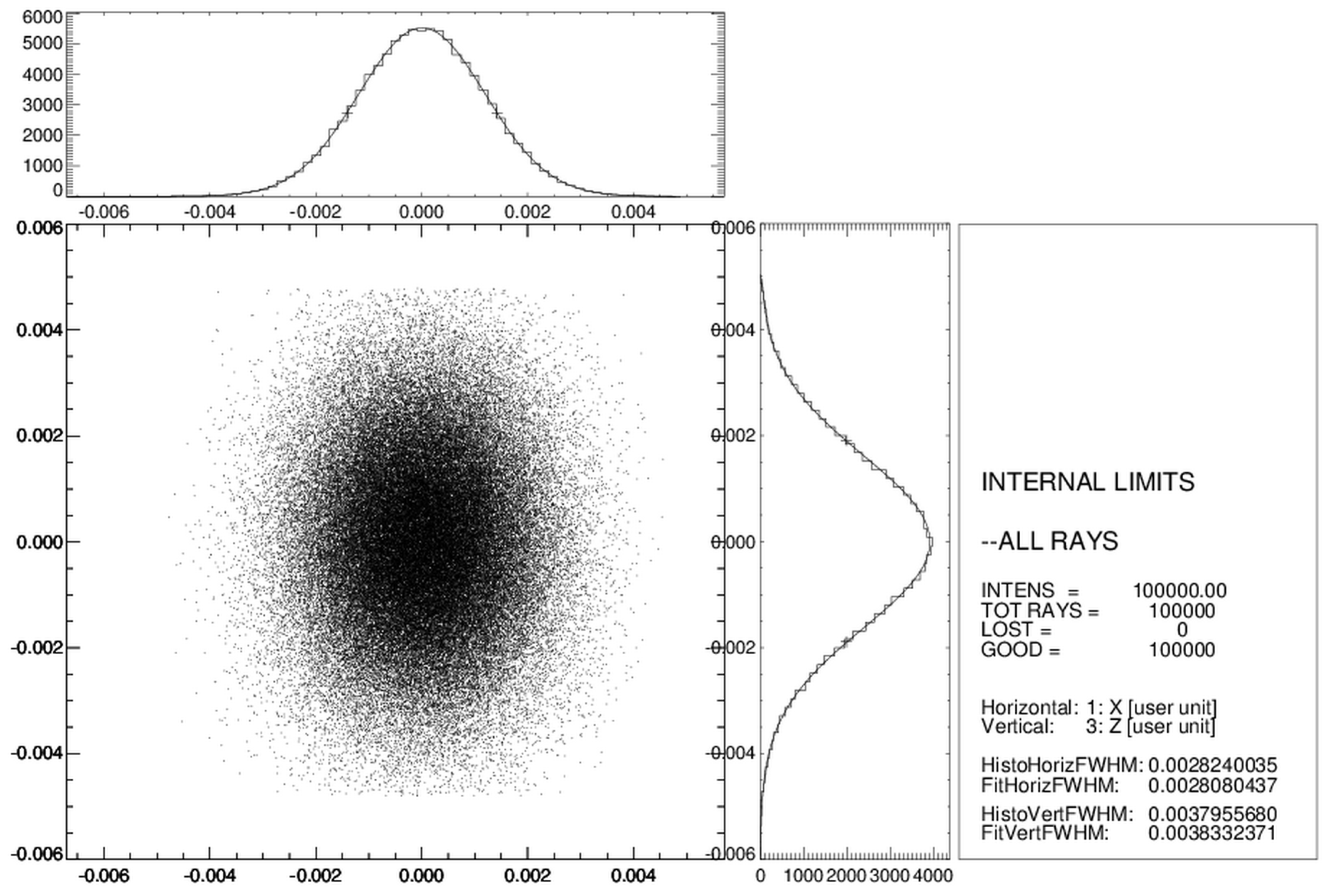
The initial set of rays for the SHADOW ray tracing were generated using a program code known as TSource, written for the calculation of inverse Compton scattering on the basis of the theoretical approaches mentioned in Section 2. Using the Monte-Carlo method, the calculated dataset of source rays represented the ICS radiation inside the working solid angle limited by the input slit of the used crystal monochromator (see below). The number of rays in this simulated X-ray beam of the ICS was N = 100,000 (see Figure 4). Note that the spectrum of the X-ray beam is maximal at a photon energy of 35.5 keV, and its intensity and angular distribution are determined by the parameters of interacting laser and electron beams.
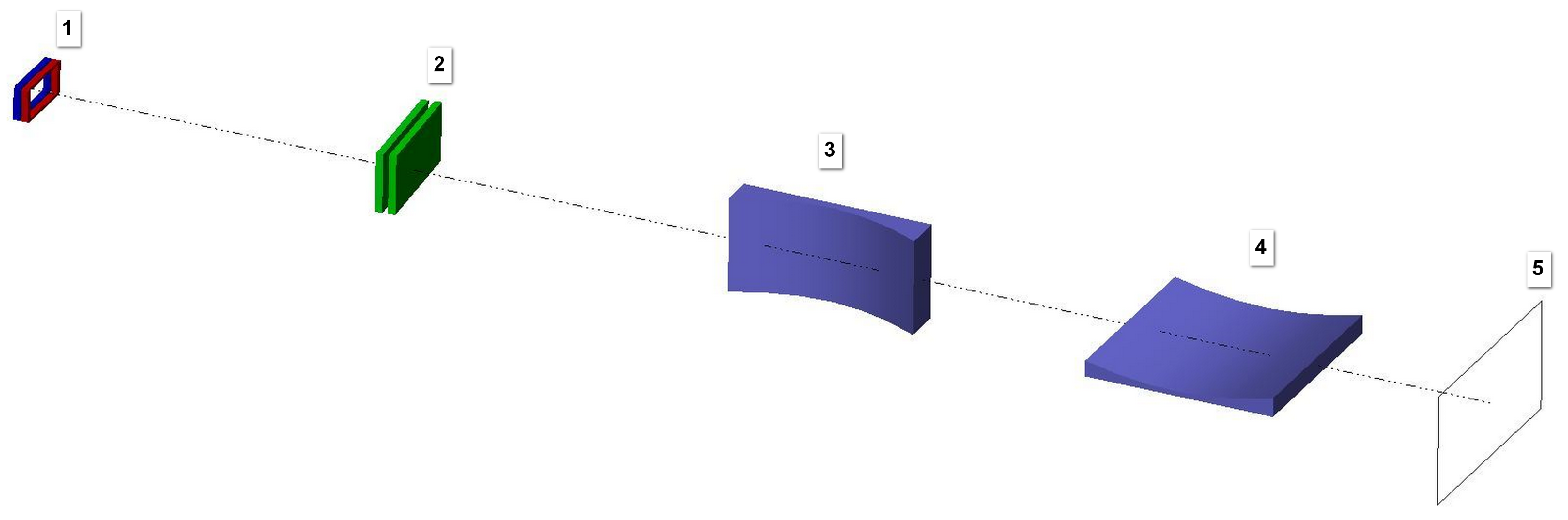
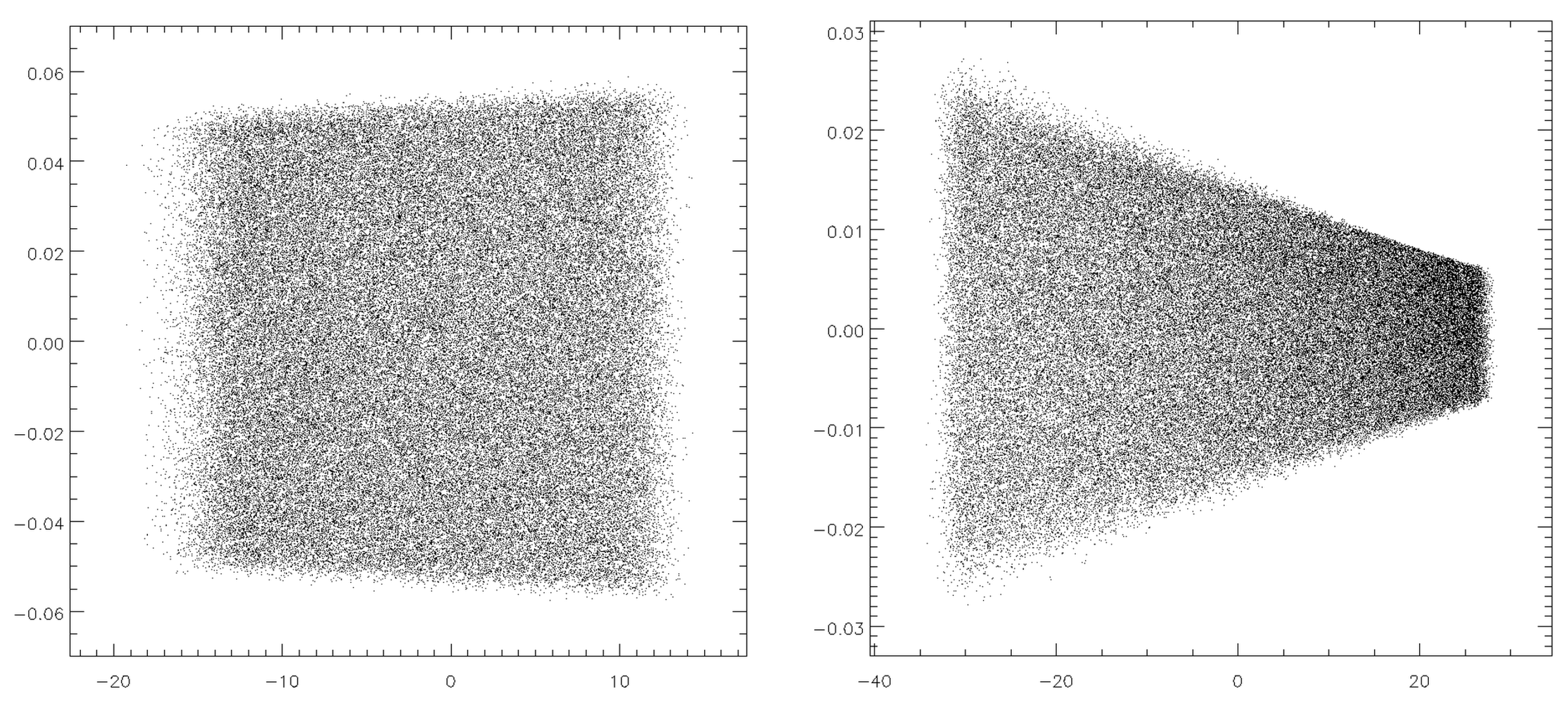
The X-ray optical layout of the simulated ICS beamline is shown in Figure 5. As mentioned above, the divergence of the input radiation was limited by the slits of the monochromator: 0.8 mm (horizontal) and 0.4 mm (vertical), located at a distance of 2000 mm from the ICS. Close to the slits, a single crystal monochromator was positioned. The monochromator was a (220) germanium crystal that was set for operations in the anomalous transmission mode (Borrmann scheme). Then, two grazing incidence X-ray mirrors in a Kirkpatrick–Baez configuration were implemented to produce a focused beam: a vertical elliptical mirror and a horizontal elliptical mirror at distances of 2610 mm and 3000 mm from the source, respectively. The parameters of the mirrors are given in Table 2. The mirror’s lengths were determined using the SHADOW code by the footprint dimensions of the beam on the mirror surfaces (see Figure 6). Both mirrors were considered to be ideally shaped, smooth, and covered with platinum. The grazing angle of the central ray in the center of a mirror was 2 mrad. The mirrors produced a demagnified image of the source in the image plane at a distance of 3500 mm from the source.
In this paper, we propose the use of a single crystal monochromator based on the anomalous transmission effect in crystals (the Borrmann effect). The main advantages of the Borrmann-type monochromator are its simple design and the fixed position of the output beam. The steady position of the X-ray beam eliminates the need for fine mechanics in controlling the deviation of the X-ray beam at different working wavelengths. It should be mentioned that in contrast to the synchrotron undulator beamlines, in the case of ICS, there is no need to filter out the high harmonics, e.g., using a double crystal monochromator.
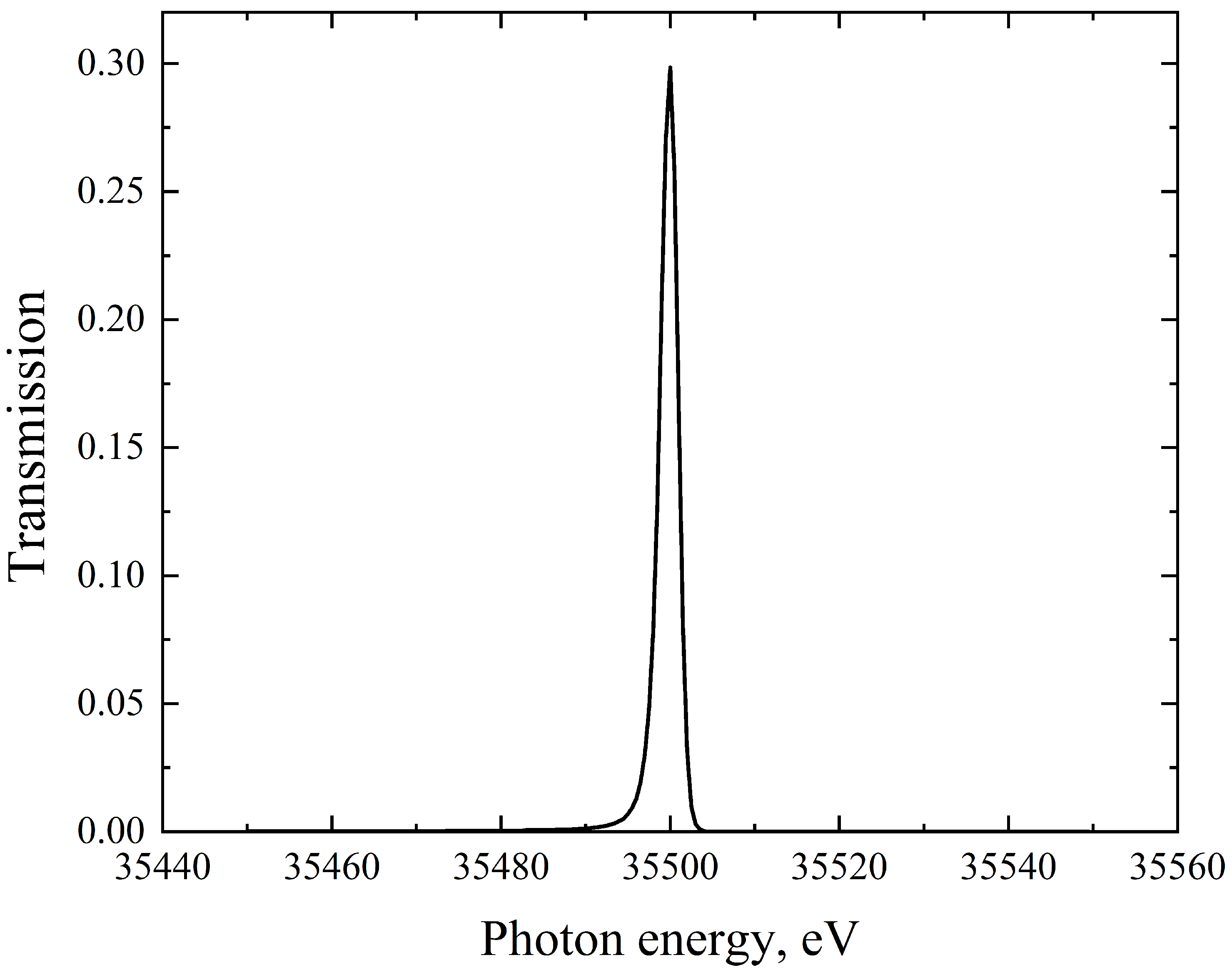
Figure 7 shows the calculated efficiency of the Borrmann anomalous transmission of a (220) germanium crystal with a thickness of 2 mm, cut at an angle of 90 to the surface (program code XCrystal 1.3 [21]). The incidence beam is set at the Bragg angle 5.01 for the photon energy 35.5 keV corresponding to the maximum of the ICS spectrum. As mentioned above, the Borrmann scheme allows one to maintain the direction of the transmitted X-ray beam for different Bragg angles and wavelengths.
Since the current version of the SHADOW code cannot simulate the anomalously transmitting Borrmann crystals, we used the following approach: a Borrmann transmission crystal was replaced by an equivalent transmitting Laue–Laue scheme similar to a channel-cut crystal monochromator [22]. The symmetry of the simulated crystal layout results in two sequential Laue reflections, which have the spectral and absorptive properties of the corresponding Borrmann crystal, while the Laue schemes can be simulated with the SHADOW code. Therefore, in our beamline model we used two identical parallel germanium plates with a thickness of 1 mm, with each separated by a distance of 4 mm to represent the Borrman monochromator. The X-ray optical characteristics of the Ge crystal were determined using DABAX databases and the BRAGG program included in the SHADOW package.
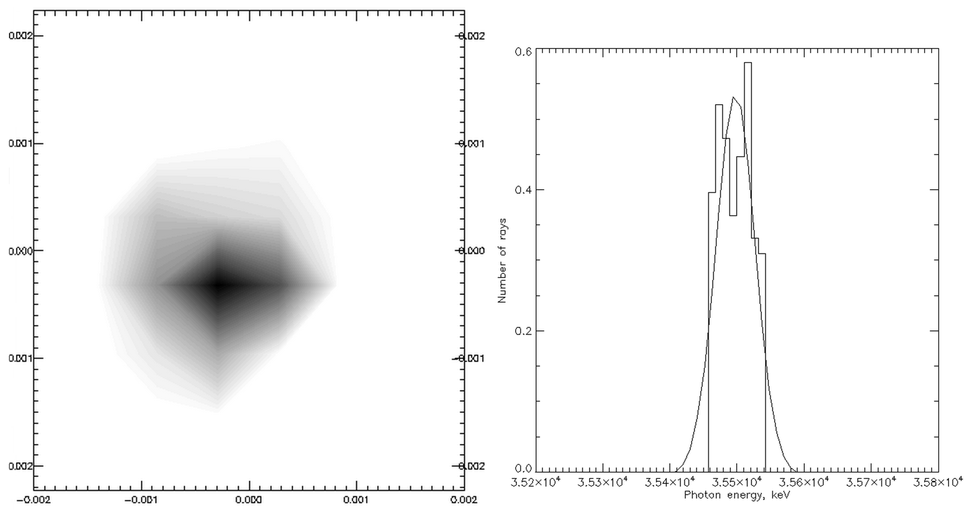
The results of the calculations and modeling using the TSource and SHADOW codes are presented in Table 3 and Figure 8. Table 3 shows the parameters of the ICS radiation after the beamline on the sample. The RMS focal spot size (see Figure 8, Table 3) is found to be about 7 × 8 m (2) with a radiation divergence of less than 1 mrad. The simulated X-ray flux within the spot is more than ph/s, and the spectral width is 0.13%. It should be noted that the focal spot size can be decreased using additional slits, if necessary.
4. Conclusions
The combination of high spectral brightness, modest size, and the low cost of ICS has led to numerous R&D efforts aimed at creating this type of equipment. They facilitate the implementation of synchrotron-like techniques such as: protein crystallography [23], X-ray phase contrast imaging [24,25], differential angiography [26,27,28], EXAFS and XANES studies [29,30], microbeam therapy [31], X-ray topography analysis [32], art history and cultural heritage investigations [33] for compact installations in many universities and research centers. In addition to existing synchrotron facilities, this will provide a wide range of students and professionals with the opportunity to work at the forefront in material sciences, nanotechnology, chemistry, biology and medicine, forensics, and microelectronic technology. Additionally, the ICS is able to provide many unique properties of radiation, such as short and ultrashort X-ray pulses [34,35] and multi-MeV beams [36,37,38] that are beyond not only X-ray tubes but synchrotron radiation sources.
In our paper, we discussed only one application of the ICS, which is relevant to the X-ray diffraction analysis of small objects. This application requires a narrow, monochromatic, low-divergence X-ray beam, which is not normally accessible to local laboratories far from a synchrotron facility. The simulation demonstrated that state-of-the-art laser, accelerator and X-ray optical systems are capable of generating needed X-ray beams despite the small value of the Thomson cross-section. There is no doubt that further development of the mentioned technologies will drive progress towards more effective ICS and its wider application.
Author Contributions
Conceptualization, A.V., R.F., V.S. and I.A.; methodology, R.F., V.S. and I.A.; software, R.F.; validation, R.F. and I.A.; formal analysis, R.F.; investigation, I.A. and R.F.; writing—original draft preparation, R.F.; writing—review and editing, I.A., R.F. and A.V.; visualization, I.A. supervision, I.A.; project administration, I.A.; funding acquisition, A.V., V.S. and I.A. All authors have read and agreed to the published version of the manuscript.
Funding
This research was carried out within the framework of the scientific program of the National Center for Physics and Mathematics (project “Nuclear and Radiation Physics”).
Data Availability Statement
Data sharing not applicable.
Acknowledgments
The authors are grateful to S.N. Polyakov and N.L. Popov for fruitful discussions.
Conflicts of Interest
The authors declare no conflict of interest.
References
- Günther, B.; Gradl, R.; Jud, C.; Eggl, E.; Huang, J.; Kulpe, S.; Achterhold, K.; Gleich, B.; Dierolf, M.; Pfeiffer, F. The versatile X-ray beamline of the Munich Compact Light Source: Design, instrumentation and applications. J. Synchrotron Radiat. 2020, 27, 1395–1414. [Google Scholar] [CrossRef] [PubMed]
- Du, Y.; Yan, L.; Hua, J.; Du, Q.; Zhang, Z.; Li, R.; Qian, H.; Huang, W.; Chen, H.; Tang, C. Generation of first hard X-ray pulse at Tsinghua Thomson Scattering X-ray Source. Rev. Sci. Instrum. 2013, 84, 053301. [Google Scholar] [CrossRef] [PubMed]
- Bazzani, A.; Cardarelli, P.; Paternò, G.; Placidi, M.; Taibi, A.; Turchetti, G. BoCXS: A compact multidisciplinary X-ray source. Phys. Open 2020, 5, 100036. [Google Scholar] [CrossRef]
- Dupraz, K.; Alkadi, M.; Alves, M.; Amoudry, L.; Auguste, D.; Babigeon, J.L.; Baltazar, M.; Benoit, A.; Bonis, J.; Bonenfant, J.; et al. The ThomX ICS source. Phys. Open 2020, 5, 100051. [Google Scholar] [CrossRef]
- Gibson, D.J.; Albert, F.; Anderson, S.G.; Betts, S.M.; Messerly, M.J.; Phan, H.H.; Semenov, V.A.; Shverdin, M.Y.; Tremaine, A.M.; Hartemann, F.V.; et al. Design and operation of a tunable MeV-level Compton-scattering-based γ-ray source. Phys. Rev. ST Accel. Beams 2010, 13, 070703. [Google Scholar] [CrossRef]
- Drebot, I.; Bacci, A.; Bosotti, A.; Broggi, F.; Canella, F.; Cardarelli, P.; Cialdi, S.; Faillace, L.; Galzerano, G.; Gambaccini, M.; et al. BriXs Ultra High Flux Inverse Compton Source Based on Modified Push-Pull Energy Recovery Linacs. Instruments 2019, 3, 49. [Google Scholar] [CrossRef]
- Huang, Z.; Ruth, R.D. Laser-electron storage ring. Phys. Rev. Lett. 1998, 80, 976. [Google Scholar] [CrossRef]
- Jacquet, M. High intensity compact Compton X-ray sources: Challenges and potential of applications. Nucl. Instrum. Methods Phys. Res. Sect. B Beam Interact. Mater. Atoms 2014, 331, 1–5. [Google Scholar] [CrossRef]
- Artyukov, I.; Bessonov, E.; Gorbunkov, M.; Maslova, Y.Y.; Popov, N.; Vinogradov, A. Thomson linac-based X-ray generator: A primer for theory and design. Laser Part. Beams 2016, 34, 637–644. [Google Scholar] [CrossRef]
- Mușat, V.; Latina, A.; D’Auria, G. A High-Energy and High-Intensity Inverse Compton Scattering Source Based on CompactLight Technology. Photonics 2022, 9, 308. [Google Scholar] [CrossRef]
- Hornberger, B.; Kasahara, J.; Ruth, R.; Loewen, R.; Khaydarov, J. Inverse Compton scattering X-ray source for research, industry and medical applications. In Proceedings of the International Conference on X-ray Lasers 2020, Online, 8–10 December 2020; Bleiner, D., Ed.; International Society for Optics and Photonics, SPIE: Bellingham, WA, USA, 2021; Volume 11886, p. 1188609. [Google Scholar] [CrossRef]
- Feshchenko, R.; Vinogradov, A.; Artyukov, I. Influence of the electron beam emittance on the polarization of a laser-electron x-ray generator. Phys. Rev. Accel. Beams 2016, 19, 114702. [Google Scholar] [CrossRef]
- Hartemann, F.; Brown, W.; Gibson, D.; Anderson, S.; Tremaine, A.; Springer, P.; Wootton, A.; Hartouni, E.; Barty, C. High-energy scaling of Compton scattering light sources. Phys. Rev. Spec. Top.-Accel. Beams 2005, 8, 100702. [Google Scholar] [CrossRef]
- Landau, L.; Lifchitz, E. Theoretical Physics. Field Theory; Editions Ellipses: Paris, France, 2004. [Google Scholar]
- Brown, W.J.; Hartemann, F.V. Three-dimensional time and frequency-domain theory of femtosecond x-ray pulse generation through Thomson scattering. Phys. Rev. Spec. Top.-Accel. Beams 2004, 7, 060703. [Google Scholar] [CrossRef]
- Sun, C.; Wu, Y.K. Theoretical and simulation studies of characteristics of a Compton light source. Phys. Rev. Spec. Top.-Accel. Beams 2011, 14, 044701. [Google Scholar] [CrossRef]
- Artyukov, I.; Savelév, A.; Shvedunov, V.; Vinogradov, A. Compton X-ray source based on 50-MeV accelerator and its applications. In Proceedings of the LXXII International Conference “NUCLEUS-2022: Fundamental Problems and Applications”, Moscow, Russia, 11–16 July 2022; Stopani, K., Zelenskaya, N., Eds.; Skobeltsyn Institute of Nuclear Physics, Amirit: Saratov, Russia, 2022; pp. 273–274. [Google Scholar]
- Welnak, C.; Chen, G.; Cerrina, F. SHADOW: A synchrotron radiation and X-ray optics simulation tool. Nucl. Instrum. Methods Phys. Res. Sect. A Accel. Spectrometers Detect. Assoc. Equip. 1994, 347, 344–347. [Google Scholar] [CrossRef]
- Lee, H.; Zhang, Z. Applicability of phase ray-tracing method for light scattering from rough surfaces. J. Thermophys. Heat Transf. 2007, 21, 330–336. [Google Scholar] [CrossRef]
- Sanchez del Rio, M.; Canestrari, N.; Jiang, F.; Cerrina, F. SHADOW3: A new version of the synchrotron X-ray optics modelling package. J. Synchrotron Radiat. 2011, 18, 708–716. [Google Scholar] [CrossRef]
- Sanchez del Rio, M.; Dejus, R.J. XOP v2. 4: Recent developments of the X-ray optics software toolkit. Adv. Comput. Methods X-ray Opt. II 2011, 8141, 368–372. [Google Scholar] [CrossRef]
- Mikhailov, I.; Baturin, A.; Kondratenko, V.; Kopilets, I.; Mikhailov, A. Prospects for application of X-ray anomalous transmission effect to monochromatization of broadband spectrum. J. X-ray Sci. Technol. 2017, 25, 25–32. [Google Scholar] [CrossRef]
- Abendroth, J.; McCormick, M.S.; Edwards, T.E.; Staker, B.; Loewen, R.; Gifford, M.; Rifkin, J.; Mayer, C.; Guo, W.; Zhang, Y.; et al. X-ray structure determination of the glycine cleavage system protein H of Mycobacterium tuberculosis using an inverse Compton synchrotron X-ray source. J. Struct. Funct. Genom. 2010, 11, 91–100. [Google Scholar] [CrossRef]
- Gradl, R.; Dierolf, M.; Günther, B.; Hehn, L.; Möller, W.; Kutschke, D.; Yang, L.; Donnelley, M.; Murrie, R.; Erl, A.; et al. In vivo dynamic phase-contrast X-ray imaging using a compact light source. Sci. Rep. 2018, 8, 6788. [Google Scholar] [CrossRef] [PubMed]
- Eggl, E.; Schleede, S.; Bech, M.; Achterhold, K.; Loewen, R.; Ruth, R.D.; Pfeiffer, F. X-ray phase-contrast tomography with a compact laser-driven synchrotron source. Proc. Natl. Acad. Sci. USA 2015, 112, 5567–5572. [Google Scholar] [CrossRef] [PubMed]
- Bessonov, E.G.; Vinogradov, A.V.; Gorbunkov, M.V.; Tur’yanskii, A.G.; Feshchenko, R.M.; Shabalin, Y.V. Laser electron-beam X-ray source for medical applications. Physics-Uspekhi 2003, 46, 872–876. [Google Scholar] [CrossRef]
- Artyukov, I.; Bessonov, E.; Feshchenko, R.; Gorbunkov, M.; Maslova, Y.Y.; Popov, N.; Dyachkov, N.; Postnov, A.; Vinogradov, S.; Vinogradov, A. Design study of Thomson Laser-Electron X-ray Generator (LEX) for Millisecond Angiography. J. Phys. Conf. Ser. 2017, 784, 012002. [Google Scholar] [CrossRef]
- Kulpe, S.; Dierolf, M.; Günther, B.; Busse, M.; Achterhold, K.; Gleich, B.; Herzen, J.; Rummeny, E.; Pfeiffer, F.; Pfeiffer, D. K-edge Subtraction Computed Tomography with a Compact Synchrotron X-ray Source. Sci. Rep. 2019, 9, 1332. [Google Scholar] [CrossRef]
- Huang, J.; Günther, B.; Achterhold, K.; Cui, Y.T.; Gleich, B.; Dierolf, M.; Pfeiffer, F. Energy-Dispersive X-ray Absorption Spectroscopy with an inverse compton Source. Sci. Rep. 2020, 10, 8772. [Google Scholar] [CrossRef]
- Huang, J.; Deng, F.; Günther, B.; Achterhold, K.; Liu, Y.; Jentys, A.; Lercher, J.A.; Dierolf, M.; Pfeiffer, F. Laboratory-scale in situ X-ray absorption spectroscopy of a palladium catalyst on a compact inverse-Compton scattering X-ray beamline. J. Anal. At. Spectrom. 2021, 36, 2649–2659. [Google Scholar] [CrossRef]
- Dombrowsky, A.C.; Burger, K.; Porth, A.K.; Stein, M.; Dierolf, M.; Günther, B.; Achterhold, K.; Gleich, B.; Feuchtinger, A.; Bartzsch, S.; et al. A proof of principle experiment for microbeam radiation therapy at the Munich compact light source. Radiat. Environ. Biophys. 2020, 59, 111–120. [Google Scholar] [CrossRef]
- Polyakov, S.; Artyukov, I.; Blank, V.; Zholudev, S.; Feshchenko, R.; Popov, N.; Yaroslavtsev, A.; Vinogradov, A. Evaluation of laser-electron X-ray source and related optics for x-ray diffractometry and topography. In Proceedings of the X-ray Lasers and Coherent X-ray Sources: Development and Applications, Prague, Czech Republic, 24–26 April 2017; SPIE: Bellingham, WA, USA, 2017; Volume 10243, pp. 124–131. [Google Scholar] [CrossRef]
- Walter, P.; Variola, A.; Zomer, F.; Jaquet, M.; Loulergue, A. A new high quality X-ray source for cultural heritage. Comptes Rendus Phys. 2009, 10, 676–690. [Google Scholar] [CrossRef]
- Gibson, D.J.; Anderson, S.G.; Barty, C.P.; Betts, S.M.; Booth, R.; Brown, W.J.; Crane, J.K.; Cross, R.R.; Fittinghoff, D.N.; Hartemann, F.V.; et al. PLEIADES: A picosecond Compton scattering x-ray source for advanced backlighting and time-resolved material studies. Phys. Plasmas 2004, 11, 2857–2864. [Google Scholar] [CrossRef]
- Hack, S.; Tóth, Z.; Varró, S.; Czirják, A. Isolated attosecond pulses of μ J energy via coherent Thomson-backscattering, driven by a chirped laser pulse. Eur. Phys. J. D 2019, 73, 77. [Google Scholar] [CrossRef]
- Albert, F.; Anderson, S.; Gibson, D.; Marsh, R.; Wu, S.; Siders, C.; Barty, C.; Hartemann, F. Design of narrow-band Compton scattering sources for nuclear resonance fluorescence. Phys. Rev. Spec. Top.-Accel. Beams 2011, 14, 050703. [Google Scholar] [CrossRef]
- Thirolf, P.; Csige, L.; Habs, D.; Günther, M.; Jentschel, M.; Krasznahorkay, A.; Filipescu, D.; Glodariu, T.; Stroe, L.; Tesileanu, O.; et al. Perspectives for photofission studies with highly brilliant, monochromatic γ–ray beams. In Proceedings of the EPJ Web of Conferences, Madrid, Spain, 25–27 June 2012; EDP Sciences: Les Ulis, France, 2012; Volume 38, p. 08001. [Google Scholar] [CrossRef]
- Petrillo, V.; Drebot, I.; Ruijter, M.; Samsam, S.; Bacci, A.; Curatolo, C.; Opromolla, M.; Conti, M.R.; Rossi, A.R.; Serafini, L. State of the Art of High-Flux Compton/Thomson X-rays Sources. Appl. Sci. 2023, 13, 752. [Google Scholar] [CrossRef]
Figure 1.
The scheme of the interaction between laser and electron beams in the inverse Compton X-ray Source (ICS). The electron beam moves along the axis z, and the laser light direction is defined by the axis . The axes y and are orthogonal to the plane . is the Rayleigh length, is the beta function, and is the collision angle.

Figure 3.
General view of the ICS developed as part of the project LEXG [17]. The linear electron accelerator and storage ring are shown together with laser and X-ray optical systems.
Figure 3.
General view of the ICS developed as part of the project LEXG [17]. The linear electron accelerator and storage ring are shown together with laser and X-ray optical systems.

Figure 4.
The simulated spatial distribution of the X-rays generated by the inverse Compton scattering. The plot is presented as an X-ray source in the format of ray-tracing SHADOW code. Top and right panels show the horizontal and vertical intensity distributions, correspondingly. The length parameters are given in mm.

Figure 5.
Schematic 3D view of the X-ray beamline showing the principle elements: 1—the output window of the ICS, 2—a Borrmann crystal monochromator (an equivalent channel-cut Laue representation is shown), 3,4—Kirkpatrick–Baez mirrors, 5—the focal (sample) plane. The input slits of the monochromator are not shown.

Figure 6.
The plot of intersection points of the rays with the elliptical surfaces of mirror 1 (left) and mirror 2 (right). This plot shows dimensions of the illuminated parts of the mirrors (footprints). The scale in the horizontal and vertical directions is different for convenience. The dimensions are shown in cm.

Figure 7.
A calculated spectral transmission curve for a (220) Ge crystal in the Borrmann scheme. The incidence angle is the Bragg angle 5.01 for a photon energy of 35.5 keV. The crystal is cut at an angle of 90 with respect to the (220) crystal plane. The thickness is 2 mm.
Figure 7.
A calculated spectral transmission curve for a (220) Ge crystal in the Borrmann scheme. The incidence angle is the Bragg angle 5.01 for a photon energy of 35.5 keV. The crystal is cut at an angle of 90 with respect to the (220) crystal plane. The thickness is 2 mm.

Figure 8.
Calculated ICS radiation parameters on the sample after the beamline: the shape and size of the focal spot (in cm) (left), the histogram of the photon energy distribution (right).
Figure 8.
Calculated ICS radiation parameters on the sample after the beamline: the shape and size of the focal spot (in cm) (left), the histogram of the photon energy distribution (right).

Table 2.
The Geometrical parameters of Kirkpatrick–Baez X-ray mirrors used in the beamline design.
| Mirror 1 | Mirror 2 | |
|---|---|---|
| Shape | elliptical | elliptical |
| Distance from the source to the mirror center, mm | 2610 | 3000 |
| Major semi-axis, mm | 1750 | 1750 |
| Minor semi-axis, mm | 3.04824 | 2.45000 |
| Mirror length, mm | 520 | 260 |
| Demagnification | 2.93 | 6.00 |
Table 3.
Parameters of the ICS X-ray radiation at the sample.
| Parameter | Value |
|---|---|
| Horizontal spot size , m | 8.08 |
| Vertical spot size , m | 7.26 |
| Spectral width , eV | 46.2 |
| Horizontal angular divergence , mrad | 0.18 |
| Vertical angular divergence , mrad | 0.61 |
| Total beamline throughput | 3.42 |
| Flux in the focal spot at the sample, ph/s | 1.4 |
| Flux density at the sample, ph/s/cm | 2.4 |
Disclaimer/Publisher’s Note: The statements, opinions and data contained in all publications are solely those of the individual author(s) and contributor(s) and not of MDPI and/or the editor(s). MDPI and/or the editor(s) disclaim responsibility for any injury to people or property resulting from any ideas, methods, instructions or products referred to in the content. |
© 2023 by the authors. Licensee MDPI, Basel, Switzerland. This article is an open access article distributed under the terms and conditions of the Creative Commons Attribution (CC BY) license (https://creativecommons.org/licenses/by/4.0/).
Share and Cite
MDPI and ACS Style
Vinogradov, A.; Feshchenko, R.; Shvedunov, V.; Artyukov, I. Ray Tracing Simulation of X-ray Microdiffraction Beamline on the Inverse Compton Source. Symmetry 2023, 15, 1068. https://doi.org/10.3390/sym15051068
AMA Style
Vinogradov A, Feshchenko R, Shvedunov V, Artyukov I. Ray Tracing Simulation of X-ray Microdiffraction Beamline on the Inverse Compton Source. Symmetry. 2023; 15(5):1068. https://doi.org/10.3390/sym15051068
Chicago/Turabian StyleVinogradov, Alexander, Ruslan Feshchenko, Vasiliy Shvedunov, and Igor Artyukov. 2023. "Ray Tracing Simulation of X-ray Microdiffraction Beamline on the Inverse Compton Source" Symmetry 15, no. 5: 1068. https://doi.org/10.3390/sym15051068
Note that from the first issue of 2016, this journal uses article numbers instead of page numbers. See further details here.