
Study of the Influence of Aspect Ratios on Hydrodynamic Performance of a Symmetrical Elliptic Otter Board


1
College of Fisheries, Ocean University of China, Qingdao 266003, China
2
Key Laboratory of Sustainable Development of Polar Fishery, Ministry of Agriculture and Rural Affairs, Yellow Sea Fisheries Research Institute, Chinese Academy of Fishery Sciences, Qingdao 266071, China
3
China National Fisheries Corp., Beijing 100160, China
*
Authors to whom correspondence should be addressed.
Symmetry 2022, 14(8), 1566; https://doi.org/10.3390/sym14081566
Submission received: 1 July 2022
/
Revised: 18 July 2022
/
Accepted: 26 July 2022
/
Published: 29 July 2022
(This article belongs to the Special Issue Test and Measurement Technology in Ocean Engineering)
Abstract
:The otter board, which is designed to maintain the horizontal opening of trawl nets, is a vital component of a trawl system. It requires a high lift-to-drag ratio, which is directly related to the trawling efficiency and economic effectiveness of the single trawler. To improve the hydrodynamic efficiency of a symmetrical elliptic otter board, four model otter boards, i.e., aspect ratio (AR) = 0.507, 0.640, 0.766, and 0.895, were designed in the present work and the effects of aspect ratios on the hydrodynamic performance of the otter board were investigated by flume tank experiments. Further, the k-ε EARSM turbulence model was adopted to analyze the hydrodynamic coefficients and the flow distribution around the otter board using the computational fluid dynamics (CFD) method. The optimal aspect ratio was obtained based on the analysis of experimental data, wherein the lift coefficient, the drag coefficient, and the lift-to-drag ratio at different angles of attack (AOA) were measured. The results show that the symmetrical elliptic otter board model is within the critical Reynolds number region when the Reynolds number is larger than 1.682 × 10⁵, and its hydrodynamic coefficient is consistent with the real otter board. When the AR was 0.766, the elliptic otter board had the best hydrodynamic performance, of which the lift coefficient and the lift-to-drag ratio were 1.05 and 1.14 fold that of the initial otter board (AR = 0.640), and the volume of the wing-tip vortex reaches a maximum. The results show the hydrodynamic performance of the symmetrical elliptic otter board, and parameter optimization of the otter board has also been provided for reference.
1. Introduction
As an essential accessory in trawl net systems, otter boards play a dominant role expanding the net mouth horizontally [1,2]. The performance of the otter board is directly related to the fishing efficiency and economic benefit of the trawl fisheries. According to the literature, the resistance of the otter board accounts for 13%~27% and even 30% of the total resistance of the whole trawl system [3,4]. Therefore, it is of great significance to improve the lift, reduce the resistance and improve the hydrodynamic efficiency of the otter board for energy conservation and emission reduction in marine fisheries and ecological environment protection.
The structure and hydrodynamic performance of different kinds of otter boards are quite varying [1]. In recent years, the hydrodynamic performances of different types of otter boards have been studied through flume tank experiments, full-scale measurements and numerical simulation. Wang et al. [5] investigated the hydrodynamic performance of a vertical V-shaped cambered otter board using wind tunnel experiments and then optimized its structure. The results showed that the otter board has better hydrodynamic performance when the curvature equals 14%, the dihedral angle is 12°, the sweepback angle is 10°, and the aspect ratio is 1.60. Liu et al. [6] studied the hydrodynamic performance of a vertical curved otter board with a small aspect ratio by the flume test, and obtained the hydrodynamic coefficient and the lift-to-drag ratio of the otter board. Xu et al. [7] studied the hydrodynamic performance of a rectangular V-shaped otter board by computational fluid dynamics (CFD) modelling and the lift coefficient of the optimized otter board (λ = 0.490, Γ = 17°) increased considerably. Sala et al. [8] designed a novel type of “Clarck-Y” otter board following the idea of improving the flow dynamics at the front end of the otter board and avoiding the generation of vortex, then it can effectively increase the lift coefficient and the lift-to-drag ratio. Sterling et al. [9,10] developed a new structure of a “batting” otter board, which can be fully operated at a low angle of attack and flexibly adjusted the angle of attack. Compared with the typical rectangular otter board, the efficiency (the lift-to-drag ratio) of the otter board increased by 3 fold. Hu et al. [11] developed a high-lift trawl door (HLTD), which can effectively increase the lift coefficient and the lift-to-drag ratio of the otter board through the usage of airfoil deflectors. Takahashi et al. [12] designed a “biplane-type” otter board by numerical simulation, and verified the numerical model through the flume test. The corresponding hydrodynamic performance has been further validated through comparisons between numerical modelling and the model-scale experiments. Moreover, the effects of aspect ratio (AR), relative camber (RC), and more structural parameters on the hydrodynamics of otter boards were investigated via the experimental and numerical methods [13,14,15,16,17,18,19].
Researchers have paid more attention to optimization of the otter board structure, as well as the design of a new otter board, so as to improve the hydrodynamic efficiency. Because of the advantages of low cost, convenient operation, long service life, and good stability, symmetrical elliptic otter boards have been popularized and operate successfully in trawl fishery in West Africa since the early 1990s [20]. Moreover, the aspect ratio plays an important role in the hydrodynamic performance of the otter board [13]. In this paper, the influence of aspect ratio on the hydrodynamic performance of a symmetrical elliptic otter board was studied by flume tank experiments. Based on the test data, the aspect ratio correlated to the best hydrodynamic performance of otter boards was analyzed and the most optimal one was chosen considering the purpose of improving the hydrodynamic efficiency of the otter board.
2. Materials and Methods
2.1. Model of the Symmetrical Elliptic Otter Board
The prototype of the otter board in this study is a 2.3 m2 symmetrical elliptic otter board operated on 441 kW fishing boats in the South China Sea with a towing speed of 2~3 kn. The wingspan of the otter board is l = 1.2 m, the chord c = 2.4 m and the aspect ratio AR = 0.64. Froude scaling law is selected for the flume experiments, and the conversion formula is as follows:
where 1—prototype otter board, 2—model otter board, S—plane area of the otter board, v—velocity, and s—scale ratio. The design scale ratio in this paper is 5.0.
The purpose is to study the effect of aspect ratio on the otter board, so the influences of other structural factors (such as slotting) are ignored in this study. The model otter board was made of acrylic plate, and its aspect ratio is 0.507, 0.640, 0.766, and 0.895, respectively. Model 2 was made by the uniform scaling of the prototype otter board. The other three model otter boards changed the aspect ratio of the otter board on the basis of ensuring that the otter board area remains unchanged. The specific structural parameters of the model otter board are shown in Table 1.
2.2. The Flume Test
The tank for the flume test is the circulating tank of the Hydrodynamic Laboratory of Ocean University of China, and the size of the tank is 4 m (length) × 1.2 m (width) × 1 m (high), with a stable flow rate range of 0.1~0.8 m/s. A six-component force meter sensor (measuring range 0~50 kg, accuracy 0.3%) and a Vectrino+ current meter (measuring range 0~2 m/s, accuracy ± 0.5%) are equipped on the tank, which are, respectively, used to measure the flow rate, lift, resistance and other moments data of the otter board model. Figure 1 shows the layout of the flume test. During the test, the otter board is fixed at the lower end of the six-component force meter sensor. The plane center of the otter board is 1.5 m away from the water inlet of the flume and 0.5 m away from the water surface. The test velocity is 0.2~0.5 m/s (interval 0.05 m/s), the angle of attack of the otter board is 0°~50° with 5° stepping, and the force data under various working conditions are collected, respectively. The data acquisition frequency is 100 Hz and the acquisition time is 90 s.
2.3. Numerical Simulation
The numerical simulation is carried out by ANSYS CFX 18.2, which solves the steady Reynolds-Average Navier–Strokes equations (Equation (6)) based on the framework Element-based Finite Volume Method [21].
where are the time-averaged velocities of the RANS model, is the pressure, is the density of fluid, is the kinematic viscosity corresponding to laminar and turbulent eddy viscosity, and are the Reynolds stresses denoting fluctuating components (i, j correspond to the subscripts with different flow directions).
The Standard k-ε turbulence model combined with the Explicit Algebraic Reynolds Stress Model (EARSM) is adopted for the simulation. It has been verified and validated against the wind tunnel measured data for an otter board from bottom trawls [22].
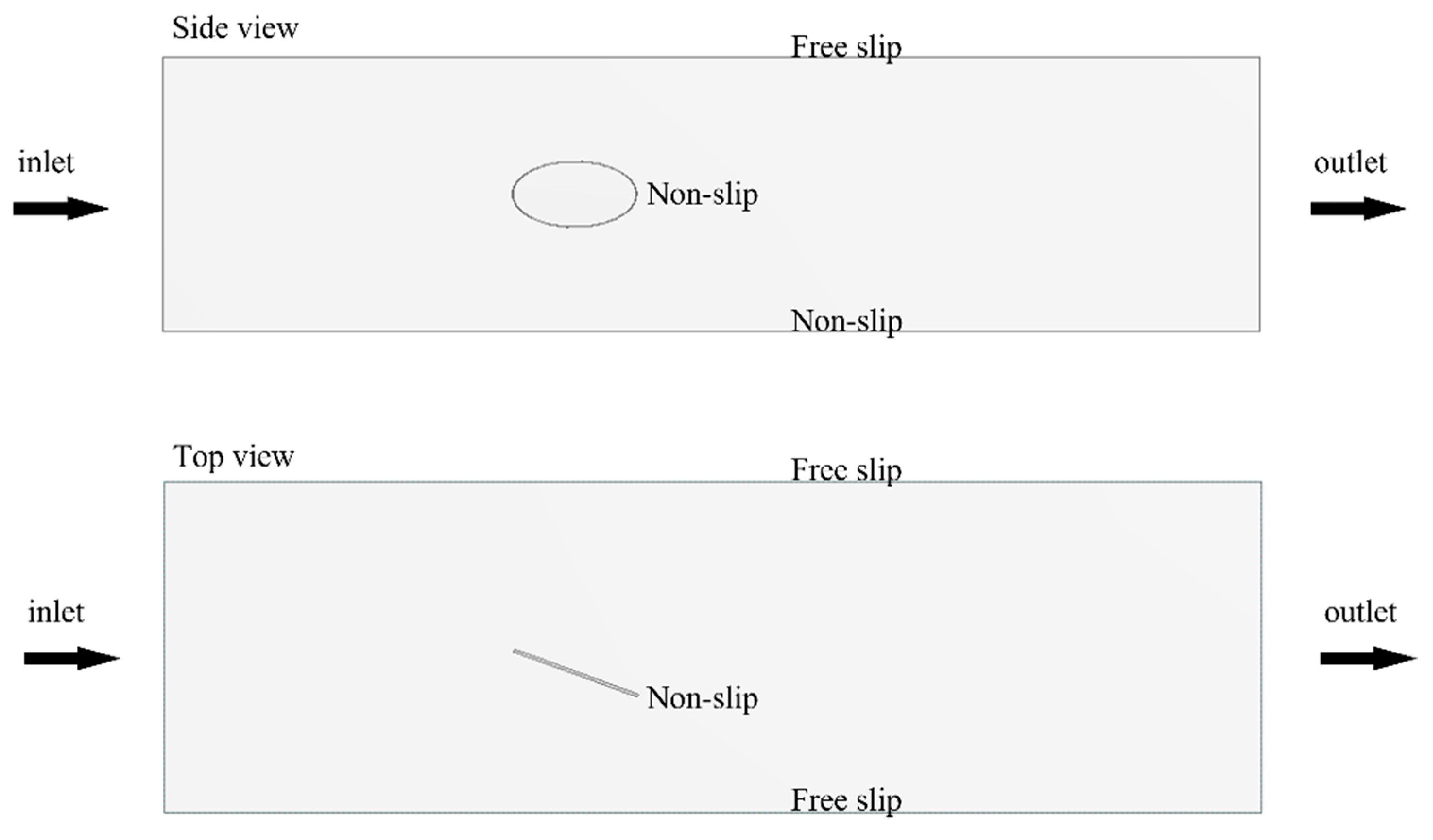
The computational domain (observation section: length 4.0 m, width 1.2 m, and water depth 1.0 m) for the CFD modeling is of the same scale as the experimental flume (Figure 1). The advection term for the velocity is discretized spatially through a high-resolution scheme in the CFX solver, whereas the turbulence terms, such as k (turbulent kinetic energy) and ε (turbulent eddy dissipation), are discretized by the 1st-order upwind scheme. The otter board model is fixed at the center of the domain, with a distance of 1.5 m from the flow entrance. The fluid is modeled as incompressible viscous fluids with a density of 998.2 kg/m3 and μ (dynamic viscosity) = 1.003 × 10⁻³ kg/(m·s). Further, the k and ε at the domain entrance were calculated following Xu et al. [15]. The current velocity was set to the typical operating speed of 0.4 m/s in model-scale experiments (approximately 2.5 kn for the operation of full-scale trawls), of which Re = 11,000. The outlet corresponds to the Neumann boundary condition, but with a relative pressure of 0 Pa. Smooth walls with non-slip conditions were used to the otter board surfaces and the bottom surface of the domain, while free slip walls were set to other walls (Figure 2).
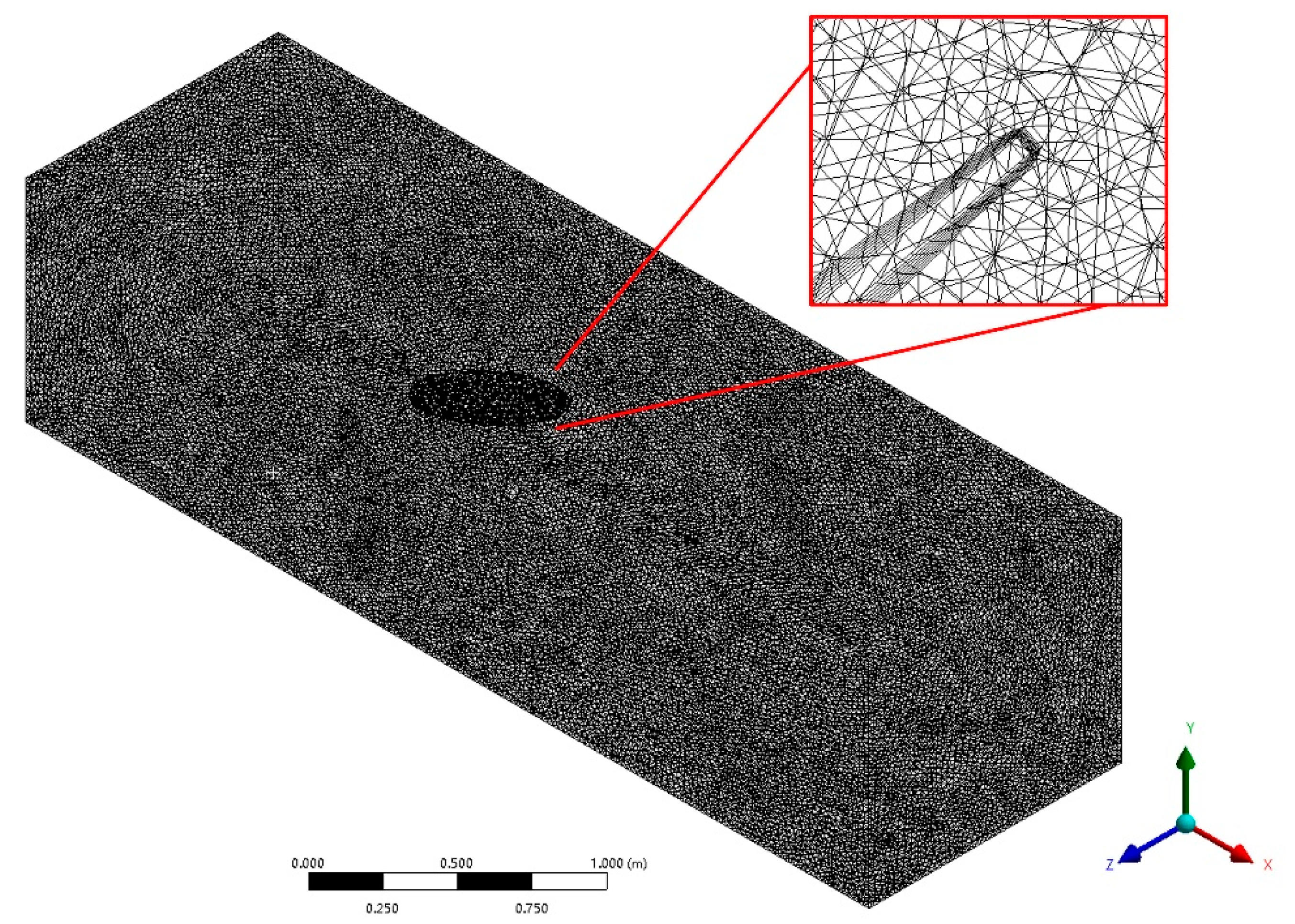
The unstructured tetrahedral grids are generated for the calculation domain, and the 8-layer prismatic layers are growing smoothly from the inner region (Figure 3). The first layer thickness is 6 × 10⁻⁴ m to ensure y+ ≥ 15. The grids independence test is also implemented to ensure the verification of the numerical simulation (Figure 4). Considering the balance of computational efficiency and accuracy, the total number of elements and nodes totaled approximately 2.66 × 10⁶ and 4.63 × 10⁵, respectively.
2.4. Data Process
The lift FL and resistance FD of the otter board were measured during the test, and the lift coefficient CL, the drag coefficient CD, and the lift-to-drag ratio K of the otter board were calculated after the strut interference correction. The calculation formulae are as follows:
where ρ is the fluid density (kg/m3); S is the area of the otter board model (m2); v is the flow velocity (m/s); c is the chord length of the otter board (m); μ is the dynamic-viscosity coefficient of fluid (m2/s); Re denotes the Reynolds number.
3. Results
3.1. Relationship between Lift, the Drag Coefficient and the Reynolds Number
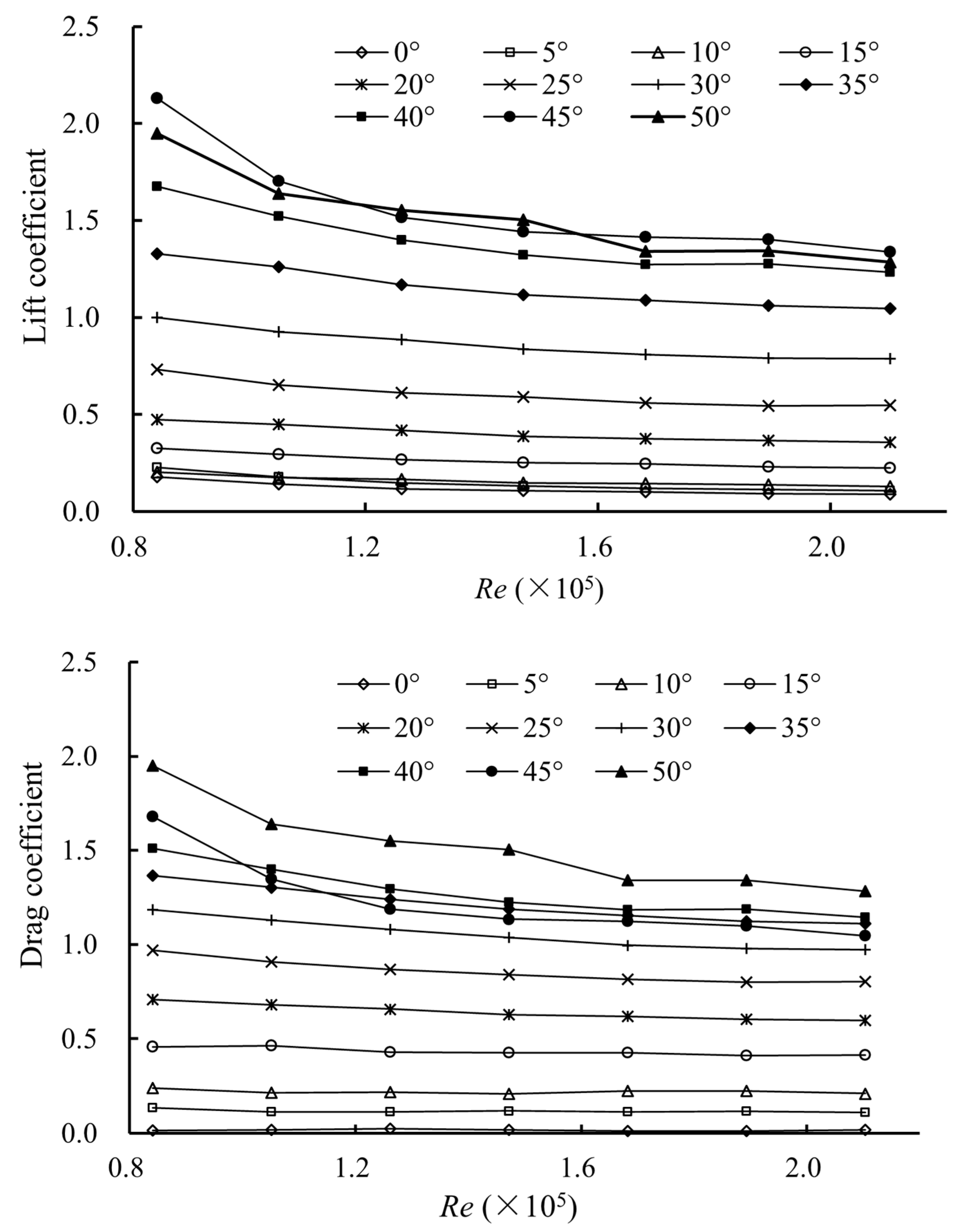
Figure 5 shows the relationship between the CL, the CD, and the K of the otter board (AR = 0.640) and Re. The Re region corresponding to the test velocities of 0.2~0.5 m/s is 0.84 × 10⁵~2.03 × 10⁵. The CL and the CD of the symmetrical elliptic otter board firstly decrease and then gradually tend to be stable. When the flow velocity is larger than 0.4 m/s (Re > 1.682 × 10⁵), which is within towing speed, the CL and the CD of the otter board tend to be stable, and it is in the critical Re region. The CL and the CD discussed below are the average values of the two coefficients within the critical Re region.
3.2. The Lift Coefficient of the Otter Board
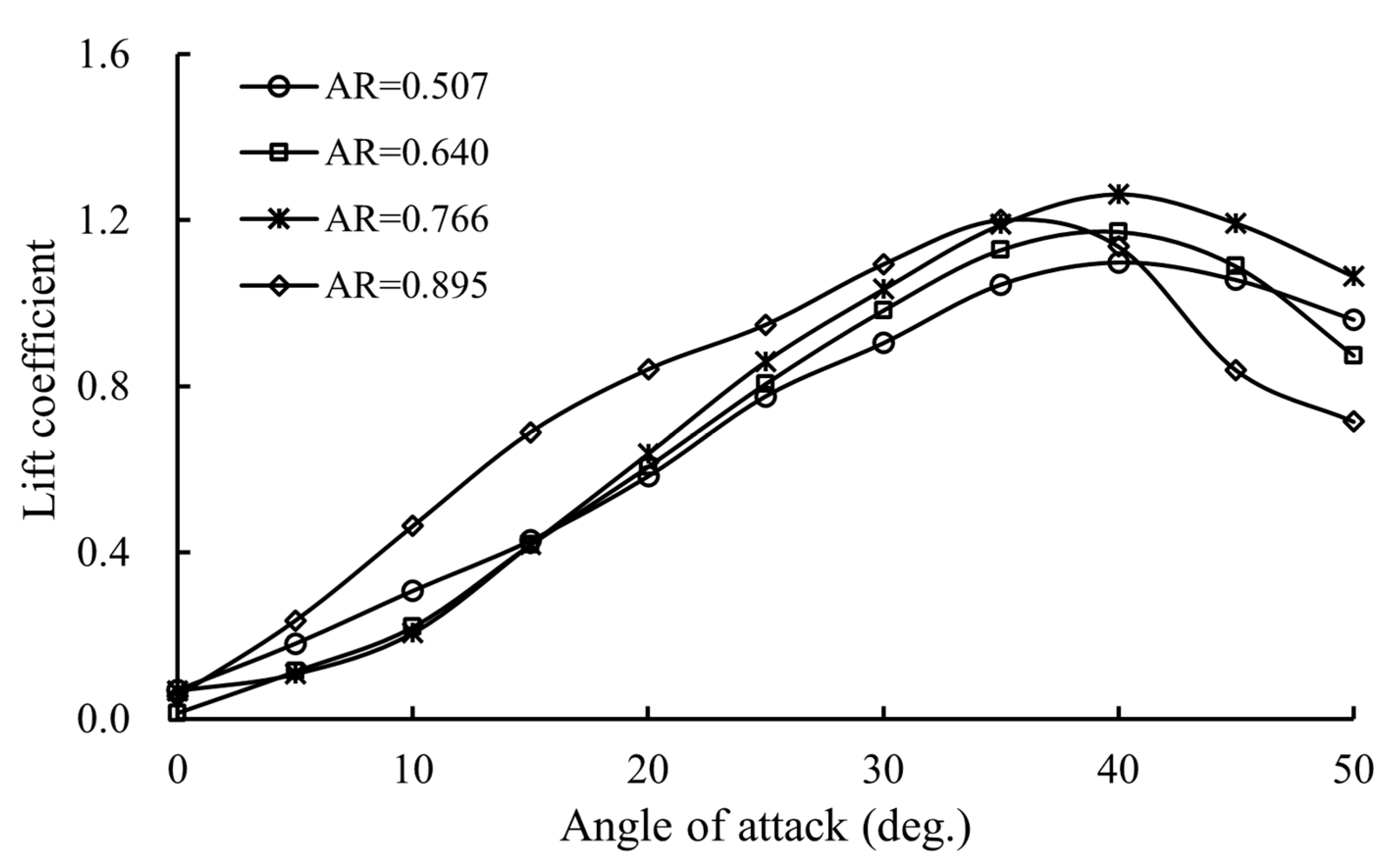
The change in the CL of the otter board with different aspect ratios with the angle of attack is shown in Figure 6. The CL of the otter board firstly increases with the rise of the angle of attack before critical AOA, and then declines. When the aspect ratio of the otter board is 0.507, 0.640, and 0.766, the maximum CL of the otter board model is 1.098, 1.172, and 1.263, respectively, with the critical angle of attack of 40°. When the aspect ratio is 0.895, the maximum CL of the otter board is 1.200 and the critical angle of attack is 35°. With the increase in aspect ratio, the CL of the otter board tends to increase at the operating angle of attack (AOA = 30°). While the maximum CL initially increases and then decreases with the increasing aspect ratio, and the critical angle of attack decreases to 35° when the aspect ratio is 0.895.
3.3. The Drag Coefficient of the Otter Board
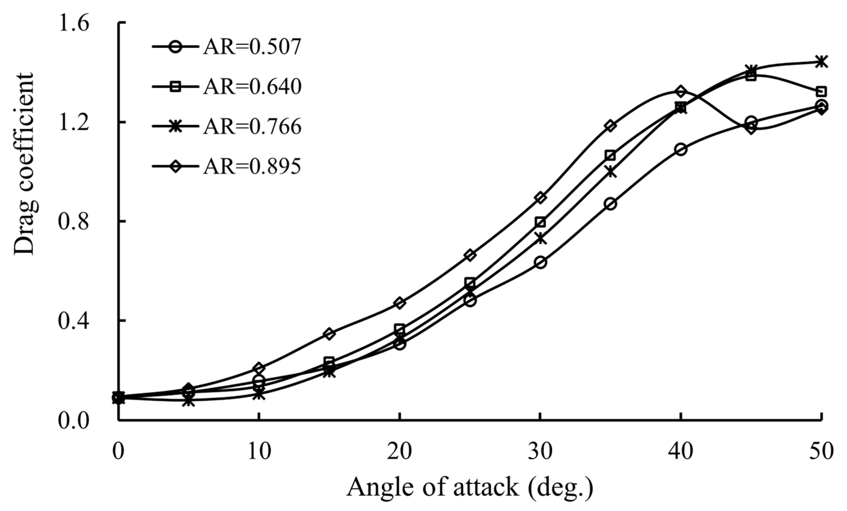
Figure 7 shows the relationship between the CD of the otter board with different aspect ratios and the angle of attack. With the increase in the angle of attack, the CD of the otter board gradually increases before the critical angle of attack. When the angle of attack reaches the critical angle of attack, the increasing tendency of the resistance coefficient gradually slows down or even decreases (such as AR = 0.895 and 0.640).
3.4. The Lift-to-Drag Ratio of the Otter Board
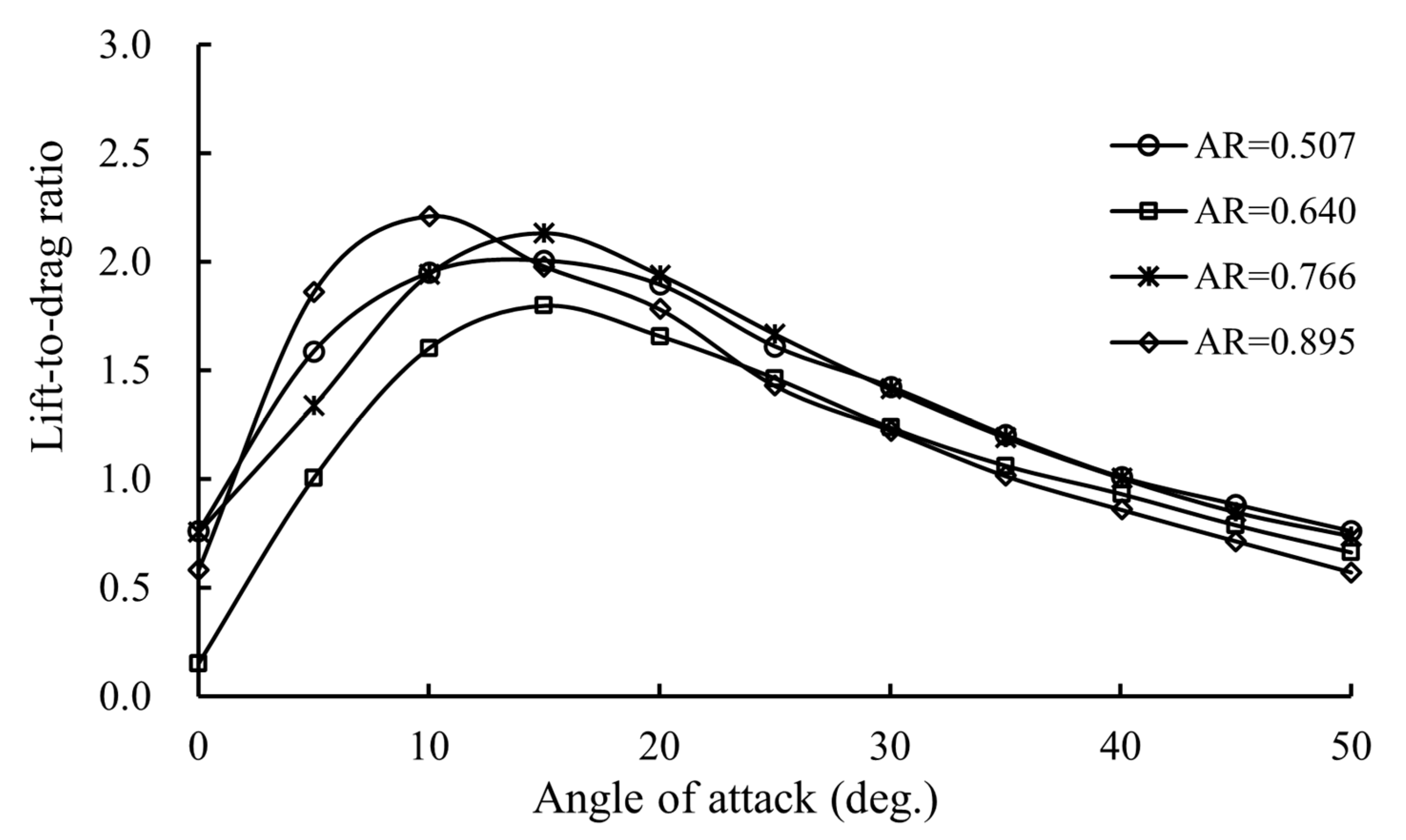
As an essential hydrodynamics parameter, the K is adopted to evaluate the operating performance of the otter board. The larger the K, the better the hydrodynamic performance of the otter board, indicating that the higher the hydrodynamic efficiency of the otter board. The relationship between the K of the otter board and the angle of attack corresponding with each aspect ratio is presented in Figure 8. It shows that the K of the otter board firstly increases and then decreases with the rise of the angle of attack. When the aspect ratio is 0.507, 0.640, and 0.766, the lift-to-drag ratio of the otter board reaches the maximum when the angle of attack is 15°, which is 2.005, 1.797, and 2.132, respectively. When the aspect ratio is 0.895, the maximum K of the otter board is approximately 2.210 when the angle of attack is 10°. When the angle of attack exceeds 15°, the K of the otter boards with aspect ratios of 0.507 and 0.766 are similar, which are higher than that of the otter board with aspect ratios of 0.640 and 0.895.
3.5. Validation
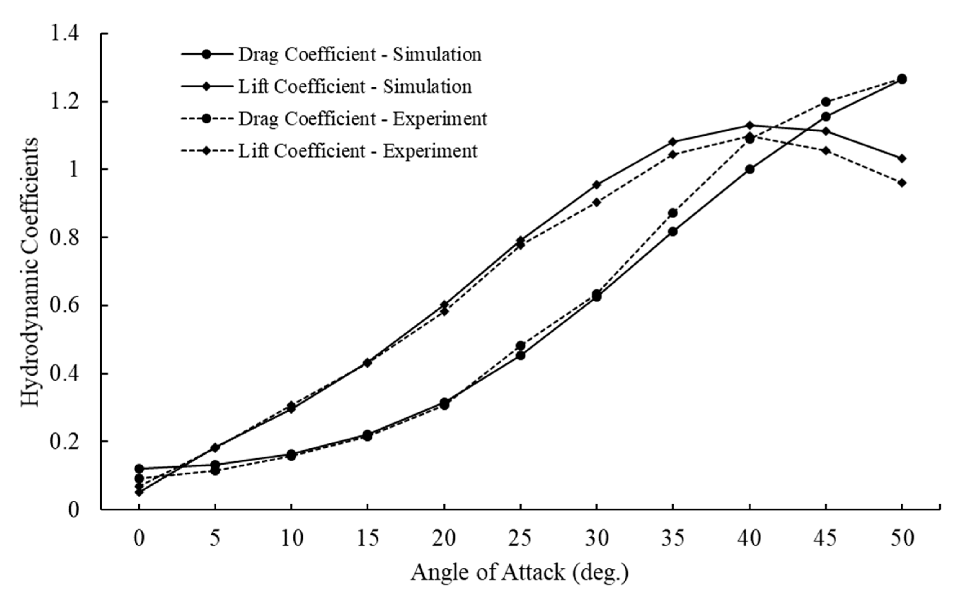
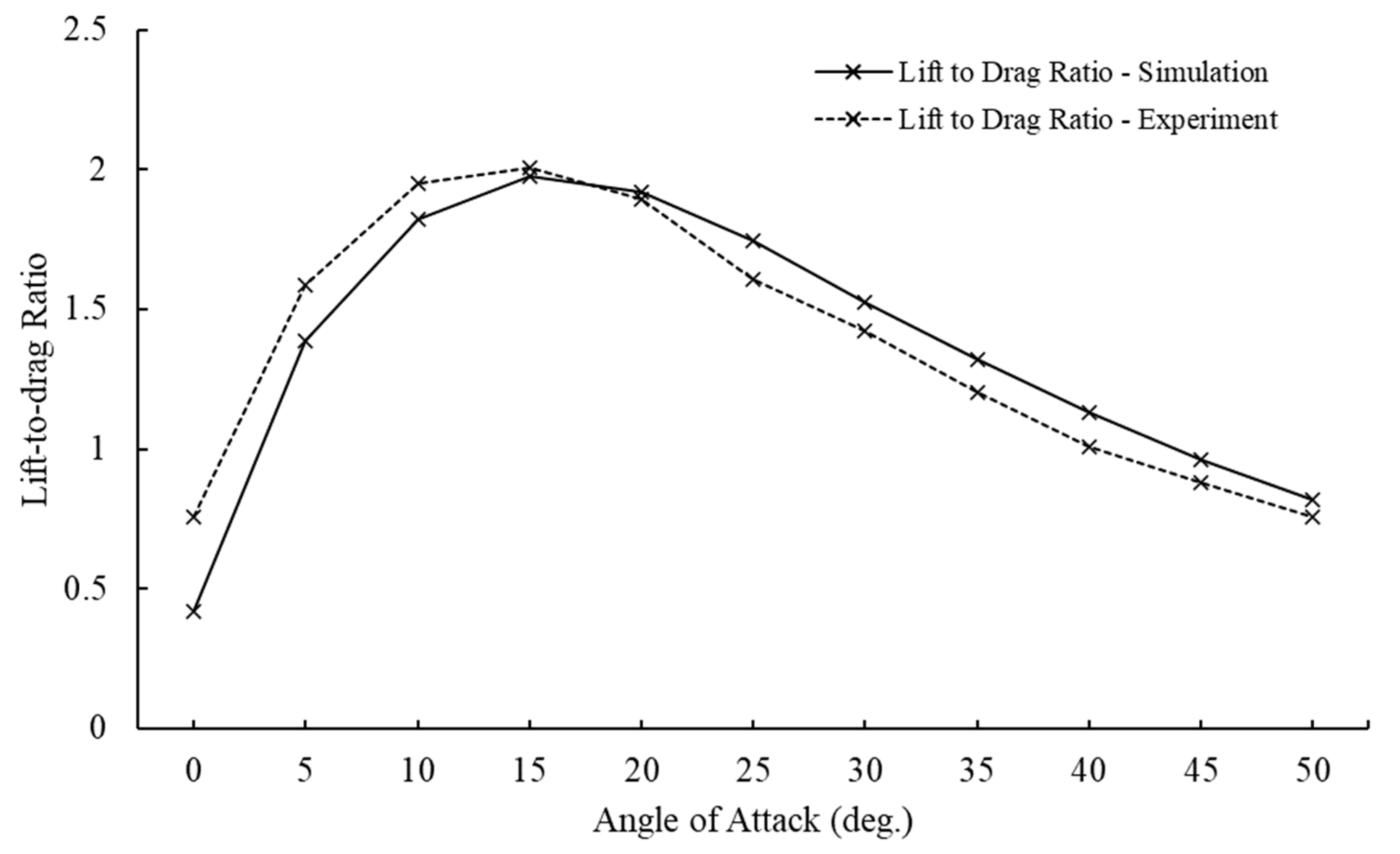
In this section, the model of the prototype otter board (AR = 0.640) is selected to verify the accuracy of the numerical simulation. The CL, the CD, and the K through CFD analysis and flume experiments are illustrated in Figure 9. Pearson correlation coefficient (R) was adopted to verify the accuracy. As shown in Figure 8, the results of numerical simulation have the same tendency against flume tank experimental data. The CL increases firstly and then drops with increasing angle of attack. The maximum simulated CL is 1.13 with the critical AOA = 40°, while the maximum physical CL is 1.10 with the critical AOA = 40°. The CL of the simulation is slightly larger than that of the flume tank experiment, and the average error of the CL between simulation and experiment is 2.76% (R2 = 0.9987). The CD increases with an increasing angle of attack. The CD of the simulation is similar to that of the experiment, with an average error of 4.80% (R2 = 0.9967). Further, it shows that the lift-to-drag ratio (K) in the numerical simulation was in good agreement with that of the flume experiment (Figure 10) with an average error of 4.70% (R2 = 0.9026). The K reaches the maximum at AOA = 15°, which is 1.98 and 2.00 in numerical simulation and flume tank experiments, respectively.
The results of the CFD simulation are similar to that of the experiment with the analogous changing trends, and the critical AOA was reproduced correctly. In summary, the EARSM k-ε model can be used to investigate the hydrodynamic performance of the otter board in the subsequent studies.
3.6. Flow Distribution around the Otter Board
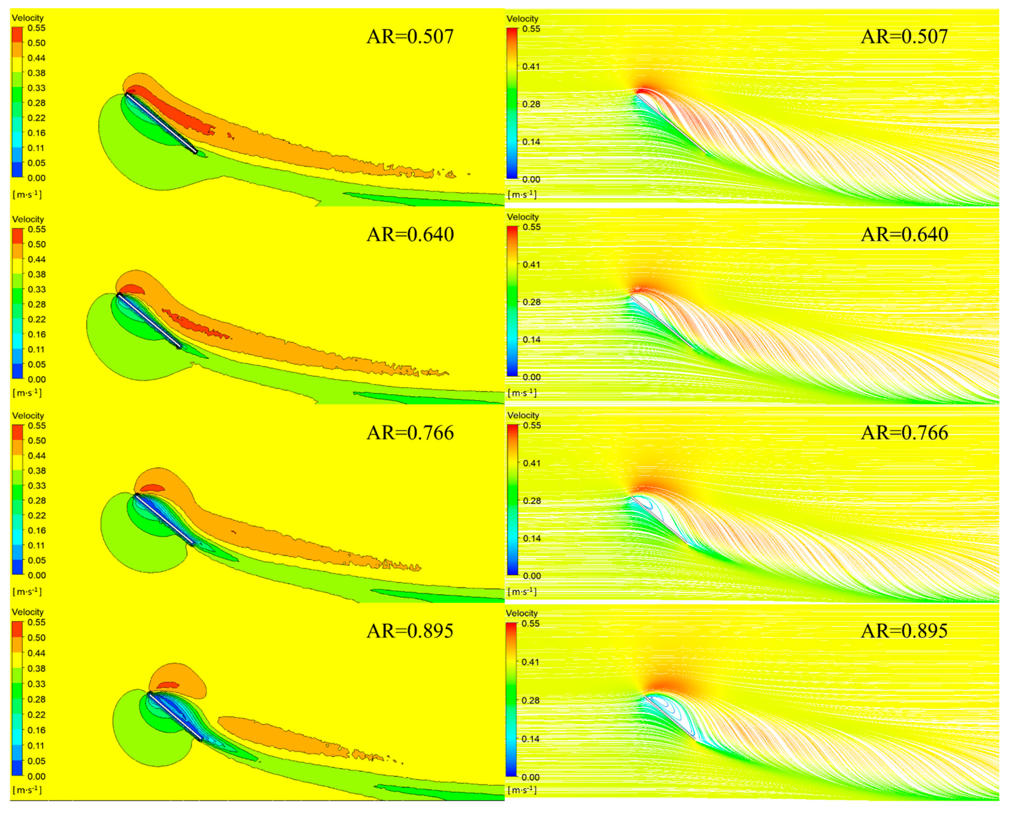
In this section, the flow field at the central section of the otter board at 0.4 m/s (within operating velocity) is studied. As shown in Figure 11, the aspect ratio has a great influence on the velocity around the otter board. The stages of flow separation and vortex around the otter board are different under different aspect ratios. When the aspect ratio is small (AR = 0.507 and 0.640), the flow separation and vortices begin to appear on the back surface of the otter board, and the area of separation and vortex are gradually expanding with the increasing ARs. At the same time, the area on the back surface of the otter board, which is lower than the inlet flow velocity, increases gradually with the increasing ARs. When the aspect ratio is large (AR = 0.766 and 0.895), the flow streamlines around the otter board have been separated from the surface completely, and the vortex covers the whole back surface of the otter board.
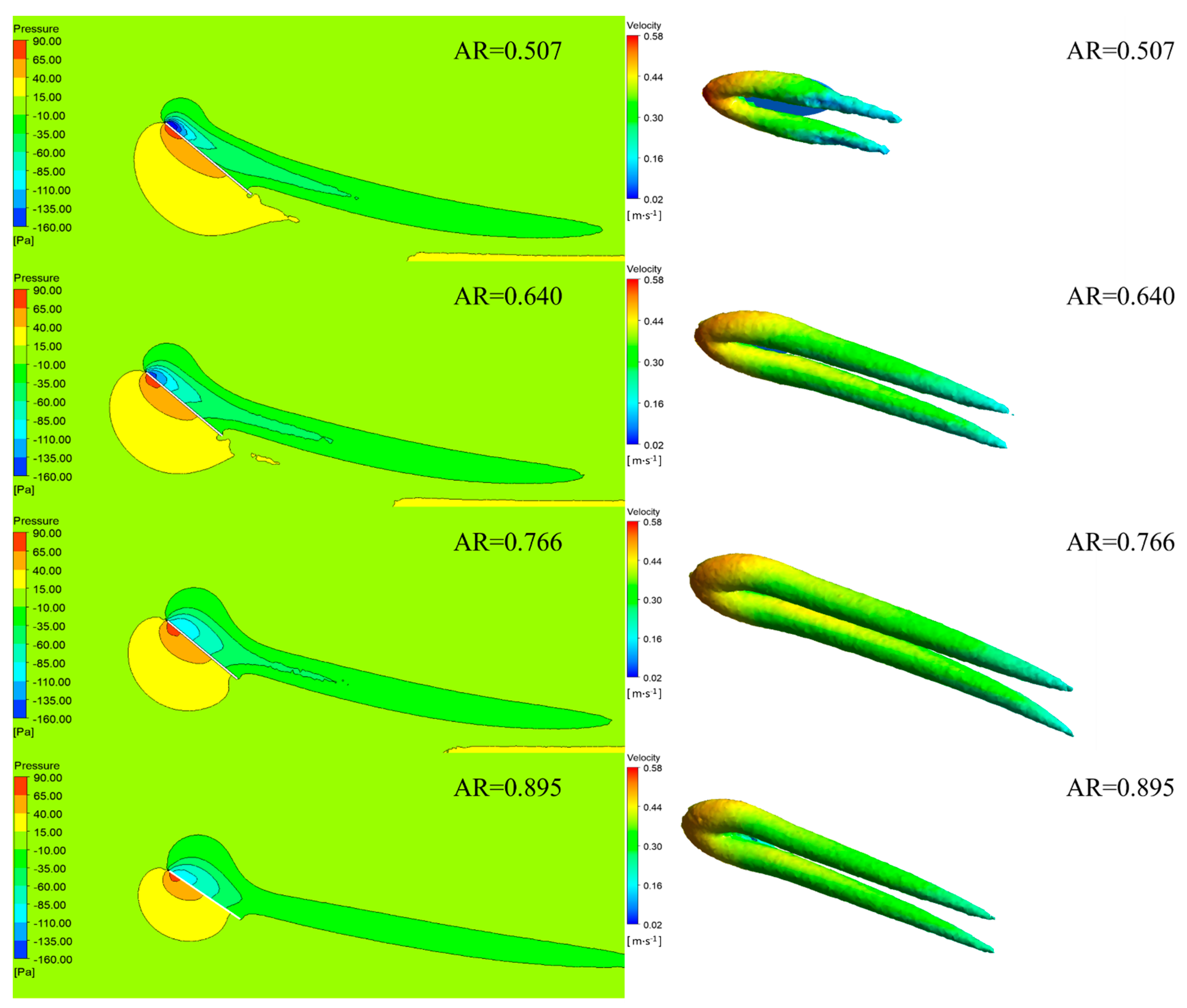
The low-pressure area on the back surface of the otter board increases firstly and then decreases with the increase in the aspect ratio (Figure 12), resulting in the pressure difference between the front and back surface of the otter board first increases and then decreases. Therefore, the lift coefficient of the otter board increases firstly and then decreases with the increase in the aspect ratios when the angle of attack reaches the critical angle, which is 1.098, 1.172, 1263, and 1.200 for the otter boards with AR is 0.507, 0.640, 0.766, and 0.895, respectively.
The wing-tip vortex has a significant effect on the lift coefficient of the otter board [13]. The vortices diagram around the otter board (Figure 12) shows that the volume of the wing-tip vortex is small when the aspect ratio is 0.507 and 0.640, and its volume is developing gradually. When the aspect ratio is 0.766, the volume of the wing-tip vortex reaches the maximum among the four otter boards. The volume of the wing-tip vortex begins to decrease when the aspect ratio is 0.895. The lift generated by the wing-tip vortex decrease due to the decrease in the vortex, which results in the reduction in the lift coefficient of the otter board.
3.7. Optimal Aspect Ratio of the Otter Board
The above research results show that the aspect ratio has a significant impact on the performance of the otter board. However, the optimal aspect ratio of this type of otter board cannot be accurately judged only based on the changing trend of these hydrodynamic parameters [22]. Therefore, this paper considers the hydrodynamic performances of the otter board at the operating angle of attack (approximately 30°), and the main hydrodynamic parameters are shown in Table 2. For the operating angle of attack of 30°, the CL tends to rise with the increase in aspect ratio, while the CD and the K fluctuate. At the operating angle, the lift-to-drag ratio of the otter board with AR = 0.766 is similar to that of the otter board with AR = 0.507, which is 14.32% and 15.54% higher than the otter board with AR = 0.640 and 0.895, respectively. However, the CL of the otter board with AR = 0.766 is 14.27% higher than that of the otter board with AR = 0.507, and the volume of the wing-tip vortex reaches the maximum among the four otter boards. Therefore, it is clarified from the hydrodynamic parameters that the otter board with an aspect ratio of 0.766 has better hydrodynamic performance, that is, the otter board has a high CL and K—1.033 and 1.413, respectively. The CL and the K of the optimal otter board are 1.05 and 1.14 fold that of the prototype otter board (AR = 0.640, CL = 0.983, and K = 1.236), so AR = 0.766 is recommended as the best aspect ratio of the symmetrical elliptic otter board in this paper.
4. Discussion
The test results show that with the increase in aspect ratio, the maximum CL of the symmetrical elliptic otter board firstly increases and then decreases. The prototype otter board has a maximum lift coefficient when the AOA was at 40°. Recalling the previous research [7], this phenomenon is different from the influence of aspect ratio on the hydrodynamic performance of a rectangular V-shaped otter board. Considering the actual operation of the symmetrical elliptic otter board, this paper suggests that the aspect ratio of the elliptic otter board is set to 0.766, which can not only improve the expansion effect of the otter board (CL-MAX), but also improve the operation efficiency of otter boards (KMAX) effectively.
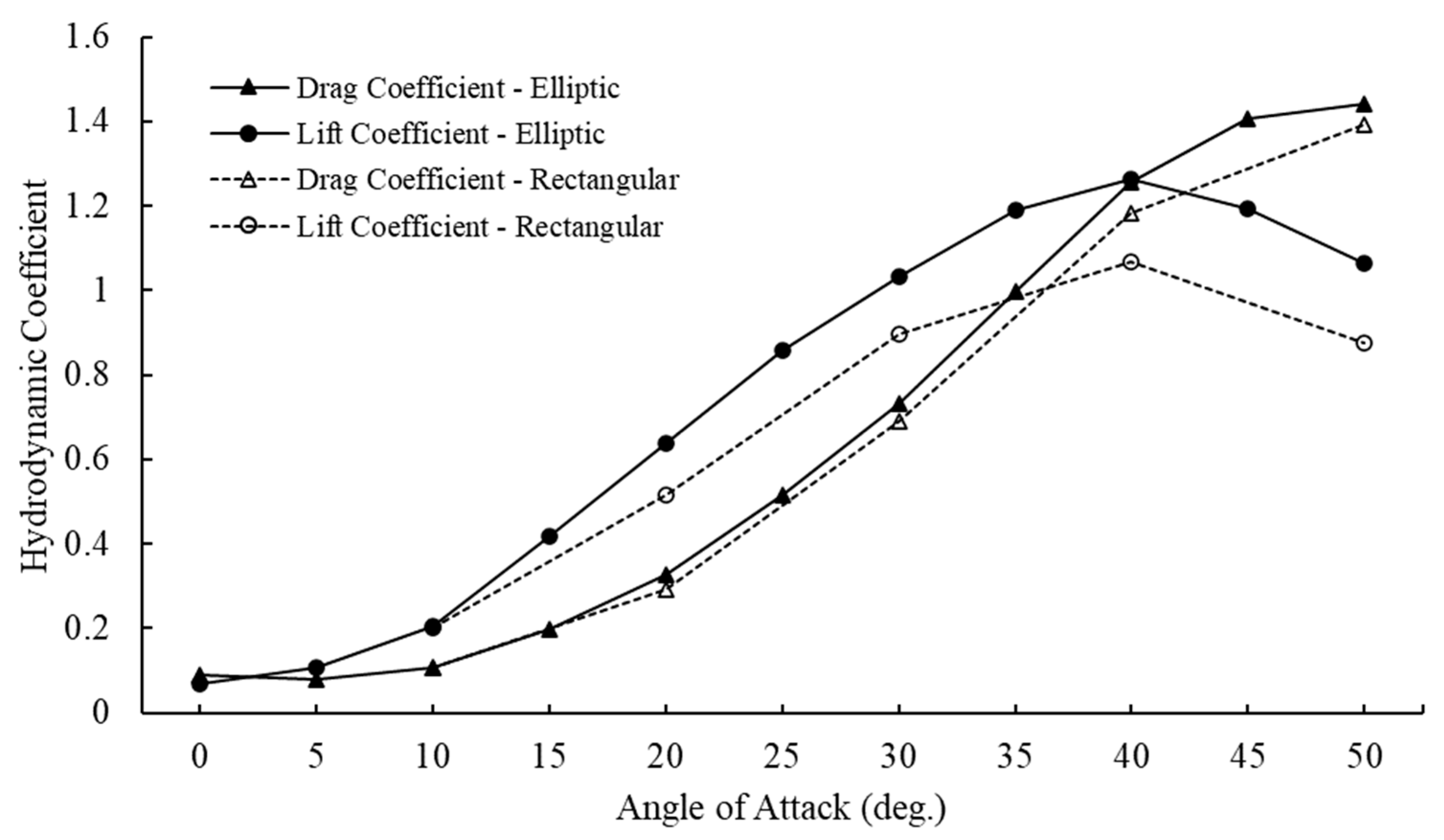
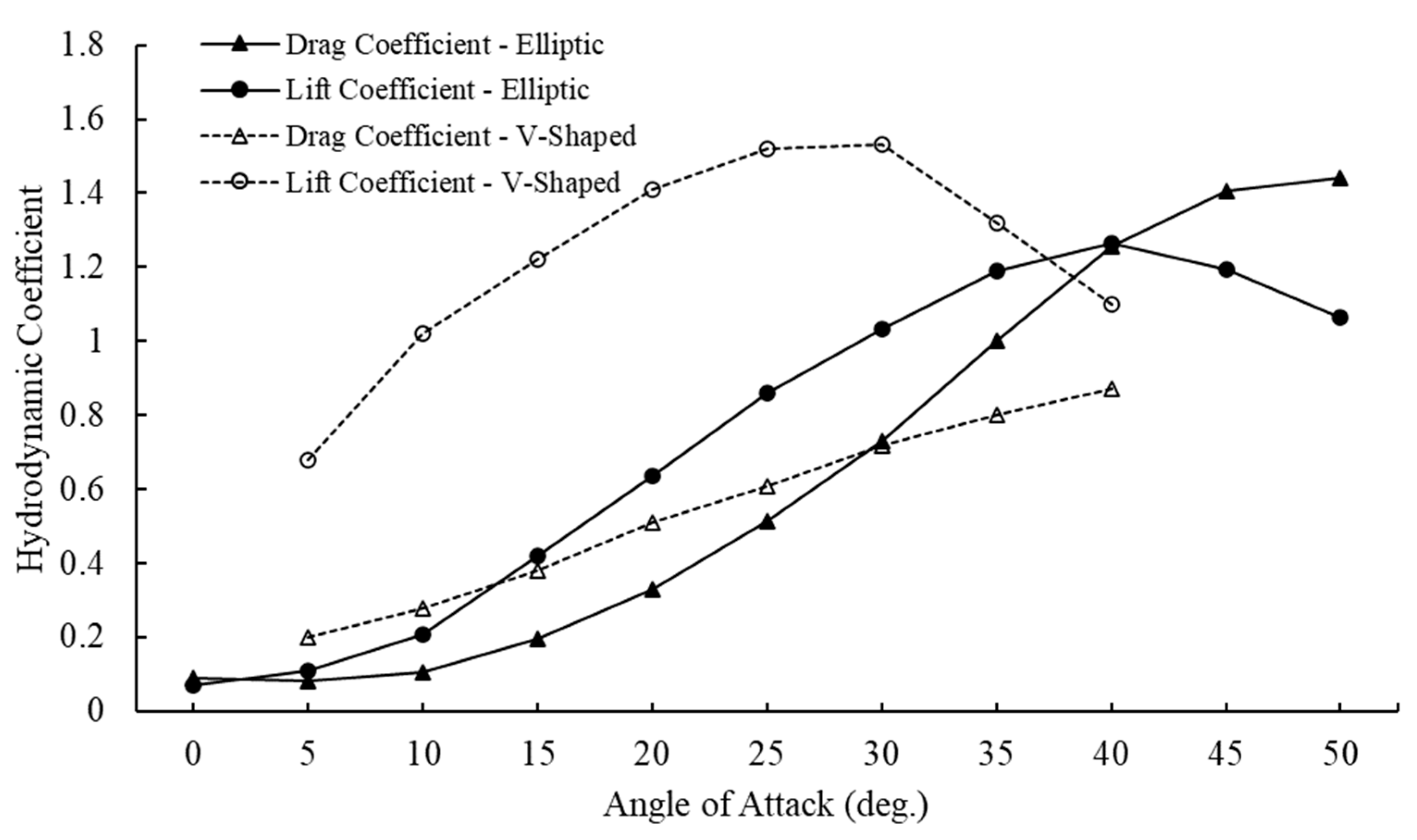
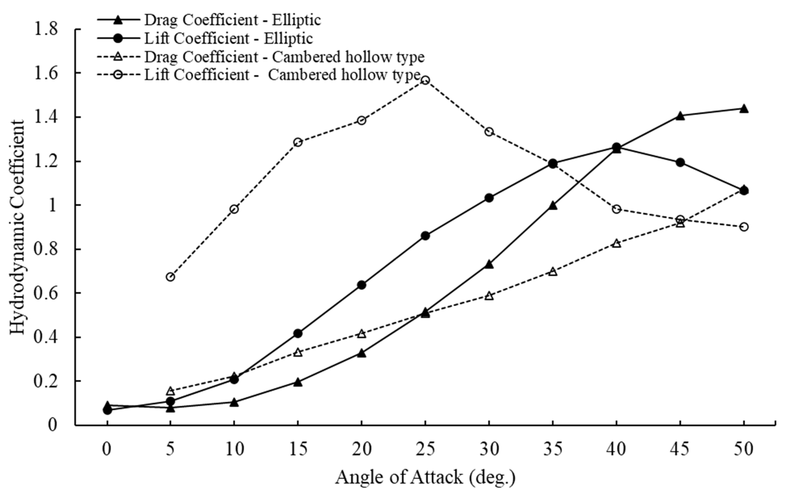
In order to further study the influence of structure on the hydrodynamic performance of the otter board, the hydrodynamic coefficient of the symmetrical elliptic otter board (AR = 0.766) with that of other symmetrical otter boards (Figure 13, Figure 14 and Figure 15). Compared with other symmetrical otter boards, the hydrodynamic coefficient of the symmetrical elliptic otter board is different. As shown in the figures, the lift coefficients of the otter boards increases first and the decrease with the increase in the AOA, and the drag coefficients increases with the increasing AOA. However, compared with the symmetrical elliptic otter board (the CL reaches a maximum of 1.26 when AOA = 40°, the K reaches a maximum of 2.13 when AOA = 15°), the maximum CL and K of the symmetrical rectangular otter board [23] are 1.07 and 1.50 when the AOA is 40° and 10°, respectively. The critical AOA of a symmetrical vertical cambered V-shaped otter board [5] and symmetrical rectangular cambered hollow otter board [17] is 30° and 25° with the maximum lift coefficients of 1.40 and 1.57, respectively. Although the maximum CL and K of this type of otter board are slightly higher than those of traditional symmetrical rectangular otter board (CL-MAX = 1.07, KMAX = 1.50) [23], they are significantly lower than those of a symmetrical vertical cambered V-shaped otter board (CL-MAX = 1.40, KMAX = 2.92) and symmetrical rectangular cambered hollow otter board (CL-MAX = 1.57, KMAX = 4.39), so this otter board can still be improved further from the perspective of hydrodynamics. Yamasaki et al. [24] confirmed that the cambered structure can considerably improve the horizontal expansion of the otter board, while the sea-trail test results of Sun et al. [25] showed that the slotting of the otter board can effectively increase the expansion performance of the otter board and improve the production of trawling operation. Therefore, in the future, it is of great necessity to further optimize the camber, slotting (slotting ratio, slotting number) and other structural parameters of the otter board to obtain the optimal structural parameters and improve the hydrodynamic efficiency of the otter board.
5. Conclusions
In this paper, the influence of aspect ratio on the hydrodynamic performance of a symmetrical elliptic otter board is analyzed by the flume model test. According to the analysis of test data, the main conclusions are drawn as follows:
- When the Reynolds number is larger than 1.682 × 10⁵, the symmetrical elliptic otter board model is within the critical Reynolds number region, and its hydrodynamic coefficient is consistent with the real otter board.
- The maximum lift coefficient firstly increases and then decreases with the increasing aspect ratio, while the drag coefficient and the lift-to-drag ratio fluctuate.
- The volume of the wing-tip vortex reaches the maximum when the aspect ratio is 0.766, and then it begins to decrease and the lift coefficient decreases when the aspect ratio is larger than 0.766.
- When the aspect ratio is 0.766, the symmetrical elliptic otter board has the best hydrodynamic performance, and its maximum lift coefficient and lift-to-drag ratio are 1.05 and 1.14 fold that of the prototype otter board, respectively.
Author Contributions
Conceptualization, L.H. and Y.L.; software and the flume test, Y.L., Q.X. and X.W.; validation, L.H., Y.L., G.W. and Q.X.; writing—original draft preparation, Y.L.; writing—review and editing, L.H., Y.L., G.W., X.W. and Q.X.; supervision, L.H., X.W. and R.Z.; funding acquisition, L.H. and Q.X. All authors have read and agreed to the published version of the manuscript.
Funding
This research was funded by National Key R & D Program of China (No. 2020YFD0901205) and the China Post-doctoral Science Foundation (No. 2019M652509).
Institutional Review Board Statement
Not applicable.
Informed Consent Statement
Not applicable.
Data Availability Statement
Not applicable.
Acknowledgments
The numerical simulation was conducted on the Linux cluster in the Lab of Marine Fishery Techniques, Ocean University of China, Qingdao.
Conflicts of Interest
The authors declare no conflict of interest.
References
- Cui, J.Z. Fishing Gears and Fishing Mythology; China Agriculture Press: Beijing, China, 1996; pp. 116–125. [Google Scholar]
- Niedzwiedz, G.; Hopp, M. Rope and net calculations applied to problems in marine engineering and fisheries research. Arch. Fish. Mar. Res. 1998, 46, 125–138. [Google Scholar]
- Yang, L. Energy saving of trawl gears. J. Zhanjiang Ocean Univ. 2000, 20, 76–78. [Google Scholar]
- Sterling, D. The Physical Performance of Prawn Trawling Otter Boards and Low Opening Systems. In AME CRC Report, Project 1.4.4; Sterling Trawl Gear Service: Brisbane, Australia, 2000; p. 204. [Google Scholar]
- Wang, M.Y.; Wang, J.H.; Zhang, X.; Yu, Y.F.; Xu, B.S. Hydrodynamic characteristics of vertical V type otter board. J. Fish. China 2004, 28, 311–315. [Google Scholar]
- Liu, J.; Huang, H.L.; Chen, S.; Li, L.Z.; Wu, Y.; Xu, G.D.; Rao, X. Hydrodynamic characteristics of low aspect ratio vertical cambered otter board. J. Fish. China 2013, 37, 1742–1749. [Google Scholar] [CrossRef]
- Xu, Q.C.; Huang, L.Y.; Zhao, F.F.; Wang, X.X.; Tang, Y.L.; Liang, Z.L.; Wan, R.; Sun, P.; Liu, C.D. Study on the hydrodynamic characteristics of the rectangular V-type otter board using computational fluid dynamics. Fish. Sci. 2017, 83, 181–190. [Google Scholar] [CrossRef]
- Sala, A.; Farran, J.; Antonijuan, J.; Lucchetti, A. Performance and impact on the seabed of an existing- and an experimental-otter board: Comparison between model testing and full-scale sea trials. Fish. Res. 2009, 100, 156–166. [Google Scholar] [CrossRef]
- Sterling, D. An Investigation of Two Methods to Reduce the Benthic Impact of Prawn Trawling. In FRDC Report, Project No. 2004/060; Fisheries Research and Development Corporation: Deakin West, Australia, 2008; p. 96. [Google Scholar]
- Sterling, D. Design, Build and Test Model Batwing Board CP2. In FRDC Report, Project No. 2008/07; Fisheries Research and Development Corporation: Deakin West, Australia, 2010. [Google Scholar]
- Hu, F.; Tokai, T.; Kinoshita, H.; Kumazawa, T. High-Lift Otter Board. U.S. Patent US8943736, 3 February 2015. [Google Scholar]
- Takahashi, Y.; Fujimori, Y.; Hu, F.X.; Shen, X.L.; Kimura, N. Design of trawl otter boards using computational fluid dynamics. Fish. Res. 2015, 161, 400–407. [Google Scholar] [CrossRef]
- Xu, Q.C.; Huang, L.Y.; Zhao, F.F.; Wang, X.X.; Tang, Y.L.; Liang, Z.L.; Wan, R.; Sun, P.; Liu, C.D.; Cheng, H.; et al. Effects of aspect ratio on the hydrodynamic performance of full-scale rectangular otter board: Numerical simulation study. Ocean Eng. 2017, 142, 338–347. [Google Scholar] [CrossRef]
- Xu, Q.C.; Feng, C.L.; Huang, L.Y.; Xu, J.Q.; Wang, L.; Zhang, X.; Liang, Z.L.; Tang, Y.L.; Zhao, F.F.; Wang, X.X.; et al. Parameter optimization of a double-deflector rectangular cambered otter board: Numerical simulation study. Ocean Eng. 2018, 162, 108–116. [Google Scholar] [CrossRef]
- Xu, Q.C.; Huang, L.Y.; Li, X.S.; Li, Y.Y.; Zhao, X.Y. Parameter optimization of a rectangular cambered otter board using response surface method. Ocean Eng. 2020, 220, 108475. [Google Scholar] [CrossRef]
- Huang, L.Y.; Li, Y.Y.; Xu, J.Q.; Xu, Q.C.; Zhao, F.F.; Wang, X.X.; Tang, Y.L.; Jia, M.X.; Liang, Z.L. Effect of Aspect Ratio on the Hydrodynamic Performance of Circular Cambered Otter Board. In Proceedings of the ASME 2018 37th International Conference on Ocean, Offshore and Arctic Engineering, Madrid, Spain, 17–22 June 2018. [Google Scholar]
- Huang, L.Y.; Li, Y.Y.; Jia, M.X.; Wang, G.; Feng, C.L.; Zhao, F.F.; Xu, Q.C.; Cheng, H. Analysis and Optimization on the Hydrodynamic Performance of Hollow Otter Board in Antarctic Krill Trawl. In Proceedings of the Thirtieth International Ocean and Polar Engineering Conference, Shanghai, China, 11–16 October 2020; pp. 1786–1793. [Google Scholar]
- You, X.X.; Hu, F.X.; Kumazawa, T.; Shiode, D.; Tokai, T. Performance of new hyper-lift trawl door for both mid-water and bottom trawling. Ocean Eng. 2020, 199, 106989. [Google Scholar] [CrossRef]
- Wang, G.; Huang, L.Y.; Wang, L.; Zhao, F.F.; Li, Y.Y.; Wan, R. A metamodeling with CFD method for hydrodynamic optimisations of deflectors on a multi-wing trawl door. Ocean Eng. 2021, 232, 109045. [Google Scholar] [CrossRef]
- Xu, B.S.; Zhang, X.; Wang, M.Y. A review on the trawl otter board evolution. J. Fujian Fish. 2010, 1, 86–90. [Google Scholar]
- Filippini, G.; Maliska, C.R.; Vaz, M. A physical perspective of the element-based finite volume method and FEM-Galerkin methods within the framework of the space of finite elements. Int. J. Numer. Methods Eng. 2014, 98, 24–43. [Google Scholar] [CrossRef]
- Balash, C.; Sterling, D.; Broadhurst, M.; Dubois, A.; Behrel, M. Hydrodynamic Evaluation of a Generic Sail Used in an Innovative Prawn-Trawl Otter Board. In Proceedings of the 34th International Conference on Ocean, Offshore and Arctic Engineering OMAE2015, St. John’s, NL, Canada, 31 May–5 June 2015; p. 6. [Google Scholar]
- Xu, Q.C.; Huang, L.Y.; Liang, Z.L.; Zhao, F.F.; Wang, X.X.; Wan, R.; Tang, Y.L.; Dong, T.W.; Cheng, H.; Xu, J.Q. Experimental and Simulative Study on the Hydrodynamics of the Rectangular Otter Board. In Proceedings of the 2nd Annual International Conference on Advanced Material Engineering, Wuhan, China, 15–17 April 2016; pp. 431–437. [Google Scholar]
- Yamasaki, S.; Matsushita, Y.; Kawashima, T.; Tomiyama, M.; Kumazawa, T.; Hirayama, M. Evaluation of a conventional otter board used in trawl fishery in Ise-wan Bay and proposal of a new design. Nippon Suisan Gakkaishi 2007, 73, 220–225. [Google Scholar] [CrossRef]
- Sun, C.L.; Yu, B.L.; Jiang, S.C.; Zhou, G.J.; Liu, D.Y.; Wang, Z.T. A study on otter board with two gaps for small single trawlers. Shandong Fish. 1998, 15, 13–15. [Google Scholar]
Figure 1.
Layout of the flume test.

Figure 2.
Boundary conditions of computational domain.

Figure 3.
Grid generation in the computational domain.

Figure 4.
Grids independence test.

Figure 5.
The relationship between the lift coefficient, the drag coefficient and the Reynolds number (AR = 0.640).
Figure 5.
The relationship between the lift coefficient, the drag coefficient and the Reynolds number (AR = 0.640).

Figure 6.
Lift coefficients of the otter boards with different aspect ratios in relation to angles of attack.
Figure 6.
Lift coefficients of the otter boards with different aspect ratios in relation to angles of attack.

Figure 7.
Drag coefficients of the otter boards with different aspect ratios in relation to angles of attack.
Figure 7.
Drag coefficients of the otter boards with different aspect ratios in relation to angles of attack.

Figure 8.
Lift-to-drag ratios of the otter boards with different aspect ratios in relation to angles of attack.
Figure 8.
Lift-to-drag ratios of the otter boards with different aspect ratios in relation to angles of attack.

Figure 9.
Hydrodynamic coefficients of the otter board related to AOA.

Figure 10.
Lift-to-drag ratio of the otter board related to AOA.

Figure 11.
Flow distributions around the symmetrical elliptic otter board with different ARs at critical AOA (velocity = 0.4 m/s). Left: Velocity contour at the central section of the otter board. Right: Flow streamline at the central section of the otter board.
Figure 11.
Flow distributions around the symmetrical elliptic otter board with different ARs at critical AOA (velocity = 0.4 m/s). Left: Velocity contour at the central section of the otter board. Right: Flow streamline at the central section of the otter board.

Figure 12.
Flow distributions around the symmetrical elliptic otter board with different ARs at critical AOA (velocity = 0.4 m/s). Left: Pressure contour at the central section of the otter board. Right: Vortices diagrams.
Figure 12.
Flow distributions around the symmetrical elliptic otter board with different ARs at critical AOA (velocity = 0.4 m/s). Left: Pressure contour at the central section of the otter board. Right: Vortices diagrams.

Figure 13.
Comparison of the hydrodynamic coefficient between the symmetrical elliptic otter board and the symmetrical rectangular otter board [24].
Figure 13.
Comparison of the hydrodynamic coefficient between the symmetrical elliptic otter board and the symmetrical rectangular otter board [24].

Figure 14.
Comparison of the hydrodynamic coefficient between the symmetrical elliptic otter board and the symmetrical vertical cambered V-shaped otter board [5].
Figure 14.
Comparison of the hydrodynamic coefficient between the symmetrical elliptic otter board and the symmetrical vertical cambered V-shaped otter board [5].

Figure 15.
Comparison of the hydrodynamic coefficient between the symmetrical elliptic otter board and the symmetrical rectangular cambered hollow otter board [17].
Figure 15.
Comparison of the hydrodynamic coefficient between the symmetrical elliptic otter board and the symmetrical rectangular cambered hollow otter board [17].


Table 1.
Parameters of the otter boards in different aspect ratios.
| Model | Wing Span/mm | Chord/mm | Aspect Ratio | Plane Area/m2 |
|---|---|---|---|---|
| Prototype | 1200 | 2400 | 0.637 | 2.261 |
| 1 | 216 | 540 | 0.507 | 0.092 |
| 2 | 240 | 480 | 0.640 | 0.090 |
| 3 | 264 | 440 | 0.766 | 0.091 |
| 4 | 287 | 410 | 0.895 | 0.092 |
Table 2.
Hydrodynamic characteristics of the otter board with different aspect ratios.
| Hydrodynamic Characteristics | Aspect Ratio | |||
|---|---|---|---|---|
| 0.507 | 0.640 | 0.766 | 0.895 | |
| Critical AOA | 40° | 40° | 40° | 35° |
| CL at critical AOA | 1.098 | 1.172 | 1.263 | 1.200 |
| CD at critical AOA | 1.090 | 1.260 | 1.257 | 1.322 |
| K at critical AOA | 1.008 | 0.931 | 1.005 | 0.859 |
| KMAX | 2.005 | 1.797 | 2.132 | 2.210 |
| AOA at KMAX | 10°~15° | 15° | 15° | 10° |
| CL at 30° AOA | 0.904 | 0.983 | 1.033 | 1.094 |
| CD at 30° AOA | 0.635 | 0.795 | 0.731 | 0.895 |
| K at 30° AOA | 1.424 | 1.236 | 1.413 | 1.223 |
Publisher’s Note: MDPI stays neutral with regard to jurisdictional claims in published maps and institutional affiliations. |
© 2022 by the authors. Licensee MDPI, Basel, Switzerland. This article is an open access article distributed under the terms and conditions of the Creative Commons Attribution (CC BY) license (https://creativecommons.org/licenses/by/4.0/).
Share and Cite
MDPI and ACS Style
Li, Y.; Wang, G.; Xu, Q.; Wang, X.; Zhang, R.; Huang, L. Study of the Influence of Aspect Ratios on Hydrodynamic Performance of a Symmetrical Elliptic Otter Board. Symmetry 2022, 14, 1566. https://doi.org/10.3390/sym14081566
AMA Style
Li Y, Wang G, Xu Q, Wang X, Zhang R, Huang L. Study of the Influence of Aspect Ratios on Hydrodynamic Performance of a Symmetrical Elliptic Otter Board. Symmetry. 2022; 14(8):1566. https://doi.org/10.3390/sym14081566
Chicago/Turabian StyleLi, Yuyan, Gang Wang, Qingchang Xu, Xinxin Wang, Rongjun Zhang, and Liuyi Huang. 2022. "Study of the Influence of Aspect Ratios on Hydrodynamic Performance of a Symmetrical Elliptic Otter Board" Symmetry 14, no. 8: 1566. https://doi.org/10.3390/sym14081566
Note that from the first issue of 2016, this journal uses article numbers instead of page numbers. See further details here.