Extending Legacy Industrial Machines by a Low-Cost Easy-to-Use IoT Module for Data Acquisition
by
 , , and
Laslo Tarjan
1,† ,
,
Ivana Šenk
1,*,† ,
,
Jelena Erić Obućina
2,†, 
Stevan Stankovski
1,† and
and
Gordana Ostojić
1,† 1
Faculty of Technical Sciences, University of Novi Sad, 21000 Novi Sad, Serbia
2
Shumadia Academy of Professional Studies, Department in Trstenik, 37240 Trstenik, Serbia
*
Author to whom correspondence should be addressed.
†
These authors contributed equally to this work.
Symmetry 2020, 12(9), 1486; https://doi.org/10.3390/sym12091486
Submission received: 18 August 2020
/
Revised: 31 August 2020
/
Accepted: 3 September 2020
/
Published: 10 September 2020
(This article belongs to the Section Computer)
Abstract
:Industry 4.0 is a paradigm that enhances industrial automation systems with the recent advances in the domain of the Internet of Things (IoT), gaining new possibilities and providing new services. Traditional industrial machines do not have IoT capabilities, and in order to integrate such a machine into Industry 4.0, there is a need for an intermediary device or system that communicates with the machine through its supported communication interfaces and protocols and forwards the communication to the global network. This paper presents the development and experimental validation of a low-cost hardware module that can easily integrate the machine’s existing control unit into the IoT and enable synchronization of the measurements and states of the variables of the machine and its environment with a cloud server. The developed module is universal, can connect to any control unit that is able to communicate through basic RS232 serial communication, and does not require the control unit to have any higher level communication protocol implemented. On the other end, the presented solution uses a dedicated smartphone application to provide remote monitoring and control of the machine through the cloud by using the synchronized variable states, as well as further possibilities for storing, processing, and analyzing the historical data from the system. The developed solution was experimentally validated on an experimental setup consisting of a conveyor belt driven by a three-phase asynchronous electromotor controlled by a programmable logic controller through a variable-frequency drive.
1. Introduction
The Internet of Things (IoT) is a paradigm for a connected world of diverse objects (computers, mechanical and digital machines, objects, animals, or people) where ordinary objects are augmented with sensory, identification, processing, and communication subsystems, allowing them to network and communicate without human intervention in order to introduce new forms of services [1,2,3,4,5].
Recent advances in automated systems envision similar pervasive networking and communication between the industrial devices, machines, robots, and computers to create an interconnected industrial system of higher value. We are currently seeing the rise of such industrial systems, referred to as the fourth industrial revolution, or Industry 4.0. Industry 4.0 serves as a comprehensive term that includes cyber-physical systems (CPS), the Internet of Things (IoT), the Industrial Internet of Things (IIoT), cloud computing, cognitive computing, artificial intelligence, and related domains [6,7,8,9].
Industry 4.0 is based on four fundamental principles [7] that should guide researchers and practitioners within this field when developing and integrating Industry 4.0 systems:
- Interoperability, which allows diverse devices to connect and communicate among themselves in order to be able to collaborate and to increase the system flexibility,
- Information transparency, which implies that the devices share their information about the sensed state of the environment and the physical state of the system and also have access to the information from the IT system,
- Decentralized decisions, enabling the industrial systems to make decisions on their own and act autonomously, and
- Technical assistance, meaning that the industrial systems can offer support to humans in making informed decisions, as well as in tasks that are too difficult or unsafe for humans.
In traditional industrial systems, a control unit constantly monitors the current state of a machine and its environment through sensor data acquisition and, accordingly, controls the machine operation. The information available at the control unit is not only important for the direct control of the machine operation, but can also give a better overview of the performance of the whole production process. An all-encompassing picture of the production of a single product often requires monitoring of diverse parameters of all machines involved in the production process [10] and even knowing the environmental conditions such as temperature, humidity, or air pressure [11]. Industry 4.0 addresses these issues by extending the automated systems into cyber-physical systems [12,13] and allowing their integration in the IoT.
Seeing that the traditional industrial systems and machines often do not include native support for IoT capabilities or even any networking capabilities, the usual solution is to upgrade the system with new control units that can be directly integrated in the IoT or new information systems on the plant level that can communicate with the machines on the local level and act as intermediaries between the local machines and the global network. Such systems are usually costly both financially and time-wise, as they involve the redesign of a part or the whole control process or introduce a new information system, and require retesting the system even to the quality requirements that were already satisfied by the original system. Our work was motivated by many examples of legacy machines and automated systems in current industrial systems, especially in developing countries, that perform well in their base function and do not require replacement or upgrade, but do not have the IoT capabilities to be included in Industry 4.0, where the idea emerged to develop an enhancement for such machines and systems with minimal financial and time investments. There are solutions for extending legacy machines for inclusion in Industry 4.0 that are based on the implementation of OPC UA (Open Platform Communications Unified Architecture) and the Modbus protocol [14,15,16] or a ZigBee module [17]. Such solutions are intended for easy integration with existing industrial machines or systems, as they use standard communication protocols, but there are cases where they cannot be applied, such as in legacy machines and systems without support for such communication protocols, which would require their subsequent implementation and make the final solution more expensive both financially and time-wise. Givenchi et al. [14] focused on economical ways of migrating an existing industrial system to the new paradigm of integrating the cyber information technologies with the physical operational technology levels. The paper [14] presented an interoperability layer requiring no changes to the existing system that maps the field device data into an ISA95-based information model. Park and Jeon [15] presented a solution based on the Raspberry Pi 3 Model B, extended to work with 24 V voltage levels, which costs around 110 USD and utilizes an application software for a universal edge gateway consisting of four parts: the equipment protocol interface, sensor interface, mapper, and OPC UA server. Toc and Korodi [16] presented a solution based on the Siemens Simatic IoT 2040 Modbus Client to OPC UA Server Wrapper hardware, priced around 390 USD, and a Teltonika RUT 240 router, priced around 140 USD, in combination with the Node-RED software. The most complex solution to the above-mentioned problem was presented by Trancua et al. [17], using hardware consisting of an ATMEGA1284 microcontroller in combination with an RS485 module for connecting the PLC with a ZigBee module for wireless communication. The solution in [17] was conceived of on a node architecture where the main node (gateway) is connected to the PLC through the RS485 module and acts as a Modbus protocol aggregating unit with the possibility of connecting to other nodes (sensors, actuators) through the ZigBee protocol. However, all these solutions require higher investments to include additional modules and communication drivers. Such investments are often not justified, as the data acquisition, storage, and analysis of the process data is often not essential for operation; however, these capabilities can potentially bring great advantages in the era of machine learning-based process analysis and decision support.
This paper presents the development and experimental validation of a new low-cost and easy-to-use hardware module, called M2Cloud (machine to cloud), which serves as an enhancement for traditional automated systems. Aiming to have a module that is small in size, very low cost, and able to adapt to various situations and connect to diverse equipment, we based the M2Cloud module on the ESP8266 controller, which is smaller in size and less expensive than the competing low-cost devices such as Arduino UNO or Raspberry Pi [18] and much more affordable than commercially available modules that enable the connection of legacy equipment to the Internet. For many legacy systems, especially where there are multiple devices and machines that need to be interconnected, the cost is often the limiting factor when deciding whether to upgrade the system. In such cases, the proposed M2Cloud module can make a big difference, making even smaller systems and machines ready for connection to the cloud and consequently allowing their inclusion in advanced systems of Industry 4.0.
The M2Cloud module provides the traditional automated systems with IoT capabilities by networking and communicating through the cloud. The provided IoT capabilities allow monitoring and control of key variables of the process from any geographical location provided that it has access to the Internet, as well as storing the acquired data for further analysis and understanding of the whole process. Generally, these capabilities are provided through the Internet, but the same solution could also be implemented as a part of a local network. The M2Cloud module utilizes a WiFi link through the ESP-01 module based on the ESP8266 controller, but it is also possible to use different wireless technologies such as Long-Term Evolution for Machines (LTE-M), Narrowband Internet of Things (NB-IoT), and Long Range (LoRa). WiFi is suitable when there is a need for data transfer rates close to real time, in indoor spaces where it is complicated to set up a cable computer network and there is a lower number of nodes. On the other hand, if the machines or automated systems are geographically distributed on a wider space, such as for water control stations, water wells, and similar, low-power wide-area network (LPWAN) technologies would be a better fit, as they are suitable for many applications that require low energy consumption and support a large coverage range and high number of nodes [19]. Such solutions can be based on LPWAN technologies such as LTE-M, NB-IoT [20,21,22], as well as Sigfox or LoRa technologies [19,23]. Unlike similar solutions [24,25,26,27,28], where the Arduino UNO or a similar microcontroller-based development environment is used in combination with the Ethernet Shield and Modbus communication protocol, the novelty of the M2Cloud module is that it is independent of the type or manufacturer of the control unit, provided that the control unit supports serial communication, as the M2Cloud module relies only on basic RS232 serial communication and does not require the control unit to have any higher level communication protocol implemented. This way, the M2Cloud module can be used for a wide range of legacy equipment, as the basic RS232 communication does not require any proprietary solutions and is common even in older or low-level control devices, while they may not have support for Ethernet communication or higher level communication protocols.
The experimental validation of the developed hardware was performed by an experimental setup for a motion control system of a conveyor belt. In the experimental setup, the conveyor is controlled by a programmable logic controller (PLC) that actuates a three-phase asynchronous motor through a variable-frequency drive (VFD). The developed M2Cloud hardware module is connected to the machine’s control unit (in this case, the PLC) through an RS232 serial communication interface. The M2Cloud module can be connected to the control unit and used for communication with the cloud with minimal changes to the control unit program. Another big advantage of the M2Cloud module over similar solutions [24,25,26,27,28] is that the M2Cloud firmware does not change for different applications, but the M2Cloud module is only parameterized when initially connected to a new system. The M2Cloud module acquires the key data from the control unit and forwards them to the Blynk server [29]. The M2Cloud module cannot directly access the data on the control unit, as can be found in similar solutions [24,25,26,27,28], but the data are read or written from the control unit. This way, the control unit has full control over the shared data, eliminating the possibility of security breaches by other parties, as the final check for the communication is always done by the control unit. The data in the cloud can be accessed either by a dedicated smartphone application developed with BlynkApp, which is available for Android and iOS smartphones, or through the Blynk HTTP RESTful API [30], which enables using GET and PUT commands for reading and writing values in the cloud and allows using the data for diverse applications, such as the Supervisory Control and Data Acquisition (SCADA) solution for remote monitoring and control [31].
The rest of the paper is organized as follows. Section 2 presents the Blynk cloud service as the chosen cloud service for the developed solution and the ways to develop the smartphone application with Blynk. Section 3 presents the developed low-cost hardware enhancement module that enables IoT integration of any traditional machine or automated system that supports serial communication. Section 4 follows with the details of the hardware and software setup for experimental validation of the solution, and Section 5 shows the experimental results. Finally, Section 6 gives the conclusions.
2. Cloud Server and Smartphone Application
Cloud computing serves as the on-demand availability of computer system resources (data storage and computing power). Clouds may be limited to a single organization (enterprise cloud) or be available to many organizations (public cloud) [32]. In the case of an enterprise cloud, the full equipment and maintenance costs are the responsibility the enterprise, while the data security and privacy can be higher and depend only on the company policies and investments in protection from cyber criminals. In the case of a public cloud, a company providing the cloud services invests in the hardware, maintenance, and development of the services and provides its resources and services as a commercial product or service to end users. Public cloud services can be free or commercial. The public clouds are usually free and publicly available for data and services in the public interest of a community; in this case, the financing is voluntary for the users. The paid public clouds often offer a similar free plan with limited resources and services.
As a cloud service for the development of the solution presented in this paper, we adopted the Blynk service [29]. Blynk is a cloud service that allows IoT integration for any type of hardware, allowing easy development of mobile applications, and provides device management, data analytics, and machine learning possibilities. The Blynk cloud service can be used through their official public cloud available at https://blynk.io/ with a free or paid plan or as an enterprise cloud by deploying a local cloud server through a Java-based server application. The solution presented in this paper uses a local cloud server running on a PC with a public IP address that allows access to the cloud through the Internet.
The Blynk IoT platform allows easy connection of the device (machine) in the cloud, designing applications for device control, as well as the tools for the analysis of the acquired data. Each device is identified with a unique 32 character alphanumeric token, which links it to a project accessed by a smartphone application or other software solution. This token can be used to access all the data stored in the cloud, but additionally, other tokens can be generated to restrict access to selected segments of the project.
Remote device control is enabled through a dedicated Blynk application developed for communication with the M2Cloud module, available for smartphones and tablets running on Android or iOS operating systems. The system can be controlled either manually by the operator using standard UI commands and indicators or through built-in programmed tools based on predefined time-based or logical conditions (limits). When developing applications with Blynk [29], among the available standard UI commands and indicators, there are buttons, switches, analogue sliders, text entry fields, LED indicators, text labels, LCDs, charts, level indicators, bars, 2 × 16 character displays, but also more sophisticated commands such as the joystick (two coordinate directions and the ENTER button), real-time clock, push up notification, e-mail notification, displaying an image array or video streaming depending on the variable state, as well as controls for smartphone sensors such as the GPS, accelerometer, gravity sensor, light sensor, or proximity sensor that can be used for automating some of the built-in control functions. The application developed with BlynkApp can be provided to the user either as a full application that gives him/her full access to all controls and their parameters or as a shared application that gives him/her access to controls, but not to all of their parameters, such as the size, position, or function of the control.
Besides the smartphone or tablet application, the cloud data can be accessed through the Blynk HTTP RESTful API [30], which requires possessing the token for data access and stating the variable name and type (int, char, long, string, etc.), since the server stores all the data as strings. For each device, it is possible to link the states of all input and output channels (both digital and analogue), as well as 255 additional virtual pins that can be of any type. Each virtual pin can store any of the basic data types (int, char, long, string, etc.), but also diverse combinations of data types through data structures, such as the LCD display structure, serial communication data structure, real-time structure, e-mail structure, etc.
3. Development of the M2Cloud Hardware Module
Traditional automated systems consist of standalone machines that are not connected to the Internet. In order to enhance such a machine with IoT capabilities, there is a need to upgrade it with an additional element (module) to enable networking and communication over the Internet. Commercially available modules for extending the control unit capabilities to connect over the Internet are usually costly, and depending on the manufacturer and the possibility of connecting to diverse control units, the price varies from tens to hundreds of USD (Table 1). In order to enable such communication capabilities for a traditional machine, we developed a low-cost hardware module M2Cloud, with a price under 10 USD (Table 2), which provides WiFi connection between any type of control unit and the cloud, while requiring only basic RS232 serial communication capability from the control unit.
The M2Cloud module connects through the Internet to the Blynk cloud server and synchronizes the key variables of the machine to the cloud server, and on the other side, it communicates with the control unit of the machine over serial communication. Unlike similar solutions [24,25,26,27,28], the M2Cloud module uses the basic RS232 serial communication, which allows the M2Cloud to communicate with various types of control units, without requiring the Ethernet connection or any higher level communication protocol. This way, the M2Cloud module is suitable for use with many different legacy systems and machines, as even older control devices usually have RS232 serial communication capabilities, while they may not have Ethernet or other communication possibilities. Consequently, in addition to the main function of the M2Cloud module to connect a machine to the cloud, it can also be used to connect several machines or systems by different manufacturers, by connecting the cloud to several control units, thus creating a virtual gateway between diverse machines or systems. We will assume that the control unit of the machine is a PLC, but it can also be any other controller with serial communication capability.
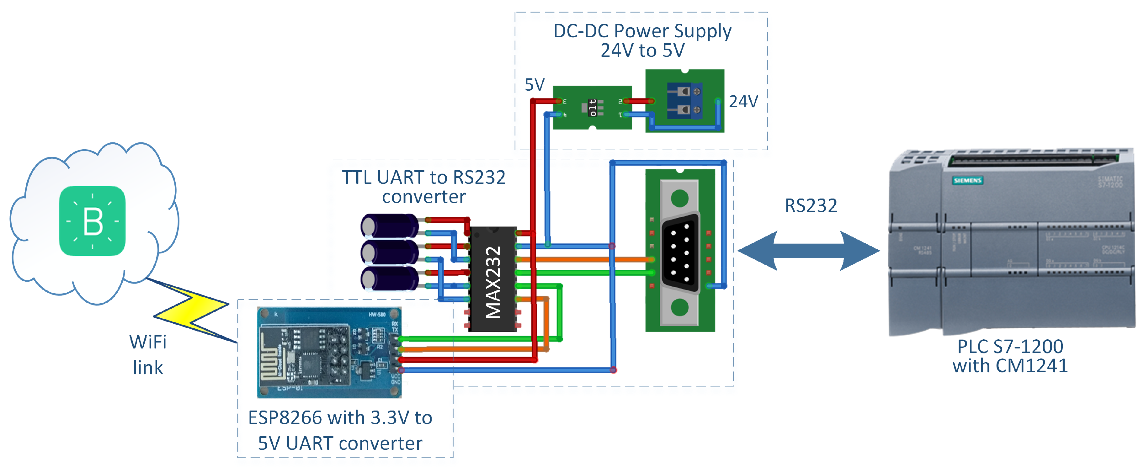
The M2Cloud module is based on the ESP8266 processor with a built-in WiFi, integrated in the ESP-01s module that contains an integrated printed circuit board (PCB) antenna with the following processor pins: Rx, Tx, IO0, IO2, EN, RST, VCC, and GND. The VCC and GND pins are connected to the 3.3 V power supply; the Rx and Tx pins are used for UART serial communication; and the EN, RST and IO0 pins are used to set the processor in the fully operational mode. The ESP-01s is used in combination with an HW-580 converter module that converts the signals on Rx and Tx pins used for serial communication from 3.3 V to TTLvoltage levels, which, along with a communication cable with the MAX232 integrated circuit, allows the module to communicate with the RS232 communication module of the PLC. The power supply of the M2Cloud module is provided by the DC-DC converter, which lowers the 24 V power supply for the PLC to 5 V, which serves as a power supply for the MAX232 circuit and which is further lowered to 3.3 V by the AMS1117 3.3 DN18 stabilizer integrated in the HW-580 module to provide the power supply for the ESP8266 processor. The current market prices for all components of the M2Cloud module are given in Table 2. The total price for all electronic components of the M2Cloud is 3 USD, and combined with a fire-resistant plastic case for DINrail, the whole module can be assembled for as low as 6.49 USD. Such a low cost makes the M2Cloud acceptable even for use with machines where connection to the Internet is not necessary, while this type of integration enables advanced possibilities for acquiring additional data, which can further be valuable for the company or the wider community. The block diagram of the M2Cloud module and the connection between the Blynk cloud server, the M2Cloud module, and the PLC are shown in Figure 1.
The firmware for the M2Cloud module is programmed in the Arduino IDE and is designed to act as a client that connects to the cloud and synchronizes its virtual pins (V1 to V255) by listening to the serial communication, which is always initiated by the main control unit for the machine (PLC). The PLC alters the values of the virtual pins by predefined commands over serial RS232 communication with the following settings: 9600 bps baud rate, 8 data bits, no parity, 1 stop bit. In addition to all virtual pins, a virtual 2 × 16 character LCD display can be used, which can be accessed through the virtual pin V0. The data structure used is to be decided by the user, for each specific application. Each data sample transferred is marked with a timestamp and its channel (the virtual pin used), and the type and interpretation of the data are left to the user to establish.
In order to make the M2Cloud module universal, all the required operational parameters can be adjusted, and the set parameters are saved in the ESPcontroller EEPROM. The operation of the M2Cloud module requires setting the following additional parameters through the serial communication during the initialization of the module:
- Blynk server token: using the command:where is a 32 character string obtained after creating the Blynk application on a smartphone.
- WiFi parameters: using the command:where is the SSID of the WiFi network and is the password for the WiFi network.
- Number of virtual pins to be synchronized: using the command:where is the number of the last virtual pin (e.g., ) and implies that the pins from to will be synchronized.
All the parameters entered during the initialization of the module are saved in the EEPROM memory of the module and do not require re-entering even after restarting the PLC. If any parameter requires altering or re-setting, the same commands can be sent again.
During normal operation, the following commands can be used with the M2Cloud module:
- is the command to read the value of the virtual pin; the module responds with ;
- is the command to modify the value of the virtual pin; the module responds by confirming .
- is the command to print to the LCD display, where x is the number of characters in a row, y is the row number, and is the text to be displayed.
- is to clear the LCD display.
The parameterized M2Cloud module connects to the specific project in the cloud through a unique static token, which is generated while adding the hardware to the project. One project can be connected to multiple devices, i.e., in this case, multiple M2Cloud modules. The maximal number of devices depends on the type of cloud server used [29]: 20 for the public Blynk cloud with a free plan, 1000 to unlimited devices for the public Blynk cloud with a paid plan (the number depends on the chosen plan), or unlimited devices (as well as unlimited number of projects or users) for a local Blynk cloud server. The Blynk platform allows every user to have multiple projects and to use the smartphone application to control their projects with a limited or unlimited number of devices (depending on the cloud type and the chosen plan). In addition, built-in services such as WebHook [29] provide the possibility to synchronize the data (through the virtual pins) among devices. It should be noted that every device has its own virtual pins, which are available through the unique token of the device and can be easily accessed through the HTTP RESTful API [30].
The M2Cloud module behaves as a client in communication with the control unit. It can read or write the data from both the control unit and the cloud only if the communication is initiated from the control unit. This way, the control unit has full control over the data read/write rate toward the cloud. The maximal data access rate on the cloud again depends on the type of cloud server used, where the public cloud limits the rate to 1 Hz (otherwise, it automatically bans the device [29]), while for the local cloud server, there are no such limitations, and the read/write rate depends on the total performance of the server. During testing, we achieved a read/write rate up to 1 kHz.
4. Experimental Setup
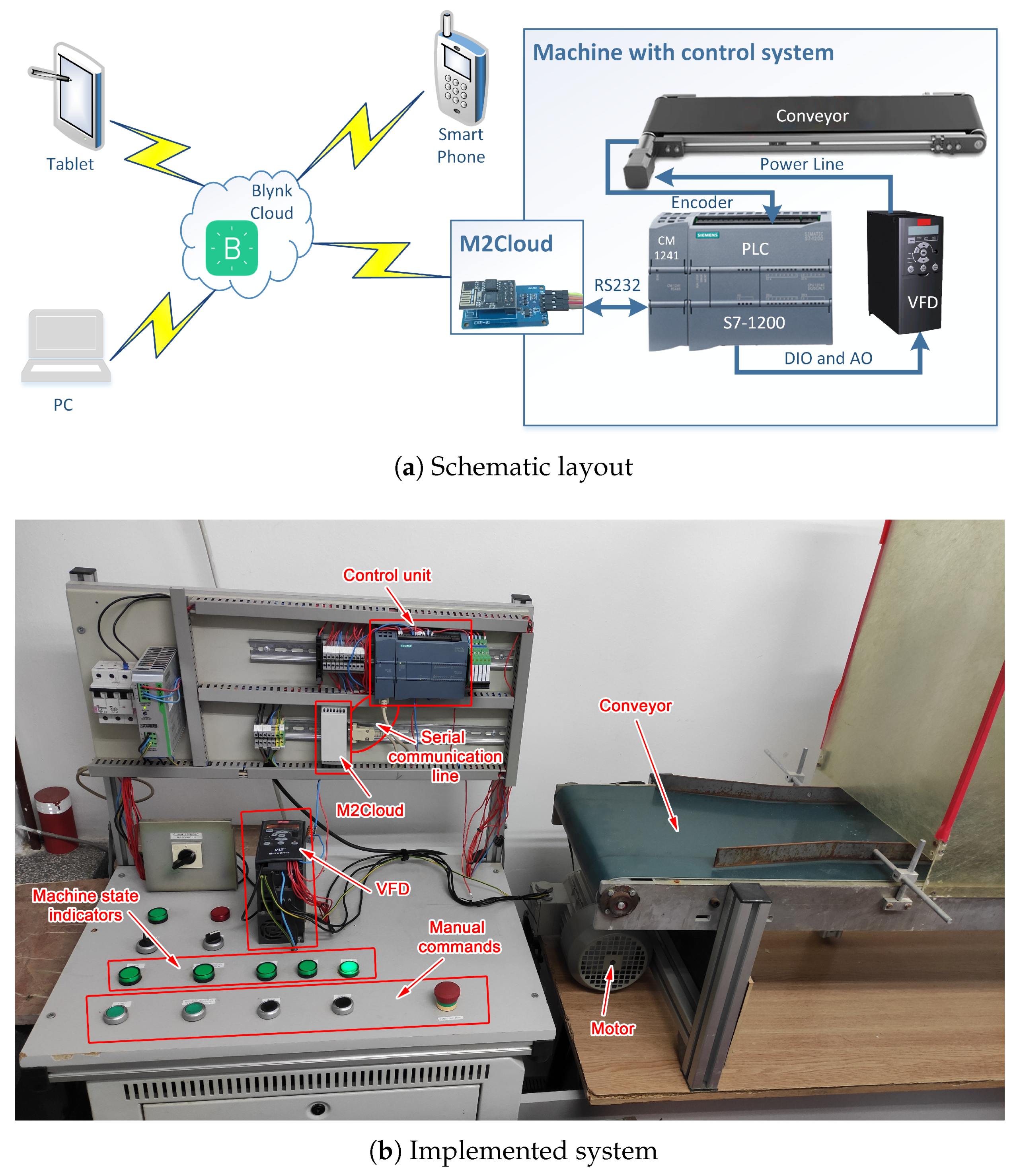
We based the experimental validation of the developed M2Cloud module on deploying the module in an experimental setup consisting of a conveyor belt actuated with a three phase asynchronous electromotor. The rotation speed and the momentum of the motor are controlled by a VFD connected with the PLC that communicates with the M2Cloud module, which synchronizes all the observed variables with the Blynk server. The user interface side consists of a BlynkApp smartphone application that gives the user the possibility to monitor and modify data stored on the cloud server and, in this way, monitor and control the whole process. Figure 2a shows the complete schematic layout of the experimental setup used for validation, while Figure 2b presents the implemented system.
4.1. Automated System
The automated system that was upgraded with the M2Cloud module within the experimental setup consists of a conveyor belt whose direction and speed are controlled by the PLC Siemens S7-1200. The conveyor belt is driven by a 100 mm diameter roller directly connected to a 0.75 kW and 1395 rpm Siemens three phase asynchronous motor at 50 Hz frequency. The conveyor has a displacement of 314.159 mm/rev and can move at a maximum speed of 7304.2 mm/s (7.3 m/s); however, in the experimental setup, the conveyor speed was limited to 3500 mm/s.
The rotation speed and the momentum of the three-phase asynchronous motor are controlled by a Danfoss VLT® Micro Drive variable-frequency drive that is connected to the PLC. The PLC controls the VFD in the following way: to set the reference for the rotational speed of the motor, the PLC uses the analogue output of 0–10 V, which is directly connected to the VFD, and to send other command signals to the VFD (Start/Stop, HALT, Emergency Stopsignals), the PLC uses the digital outputs. The VFD used in the experimental setup does not have closed-loop feedback. In order to measure the real motor output speed, a 1000 imp/revoptical encoder is installed and connected to the high-speed input of the PLC. The acceleration or deceleration ramp for the motor is set to 300 mm/s2 in the VFD configuration and cannot be changed during operation.
The machine can be controlled by the user either manually by using the push buttons or remotely. Manual control (Figure 2b) includes the Speed+ and Speed-push buttons to set point velocity (SPV), the Start/Stop push button to turn the motor on or off, and the Dir push button to select the direction of the motor’s rotation. All the push buttons are connected to the digital inputs of the PLC. The user can also control all the machine’s functions remotely in a WinCC SCADA application for the PC, as well as by using the developed smartphone application after connecting to the Blynk cloud server presented in detail in the next subsection.
4.2. Machine Monitoring and Control Application
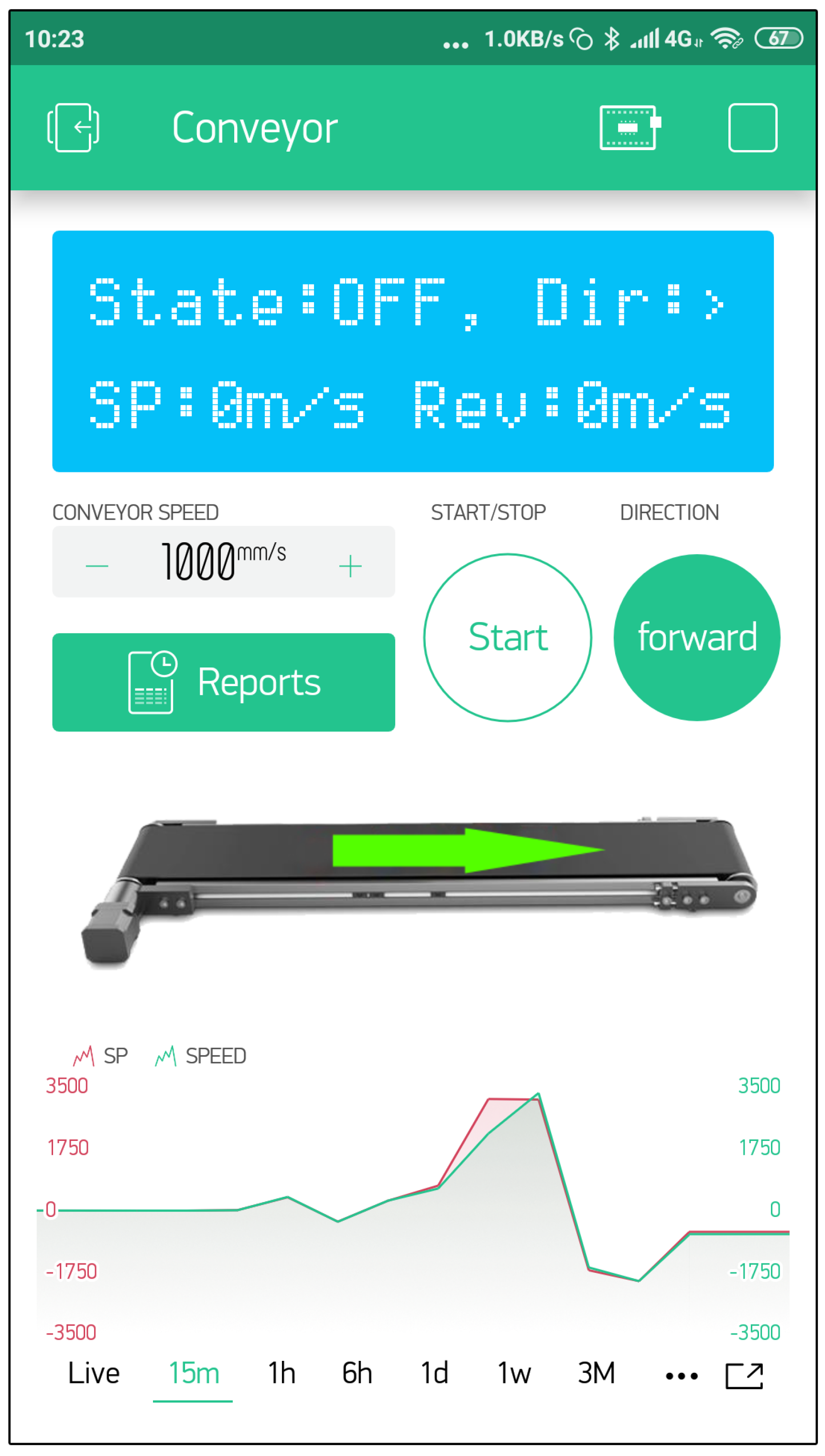
The smartphone application for machine monitoring and control for the experimental setup was developed in BlynkApp. The user interface of the developed application is shown in Figure 3. It includes an LCD display (connected to the virtual pin V0) that displays important information about the state of the conveyor (running or stopped), as well as the direction and current speed of the conveyor belt. The desired SPV (virtual pin V3) of the conveyor can be set either through direct input of the new desired set point or by the + and − buttons, which increase or decrease the speed by a predefined value (e.g., by 100 mm/s; this predefined value can be changed in the control properties). Similarly to manual control (Figure 2b), there is a Start/Stop button for starting and stopping the machine (virtual pin V1) and a Direction button for setting the direction of the motor’s rotation (virtual pin V2). There is also a visualization of the current state of the conveyor on an image with a displayed arrow indicating the moving direction of the conveyor belt. Finally, there is a plot on the bottom part of the user interface that displays two trend lines: the trend line of the desired SPV (virtual pin V4) and the trend line of the real current conveyor speed (virtual pin V5). The plot can display live data, meaning that it will immediately display any change on the virtual pins, or it can be set to display past changes in a chosen time interval, which can range from 15 min to 12 months.
The values displayed on the plot can be exported as a CSV file and sent as an e-mail attachment or read directly through the Blynk HTTP RESTful API [30], where each trend line of historical data can be downloaded by calling the GET command https://blynkserver.com/auth_token/data/pin for the adequate virtual pin, as in using the command:
- https://blynkserver.com/dMb***hcH/data/V4 for downloading the historical data for the virtual pin V4 or
- https://blynkserver.com/dMb***hcH/data/V5 for downloading the historical data for the virtual pin V5.
The server properties can be set to limit the maximum number of data points for download from the cloud. The downloaded data contain three columns, where the first one is the value, the second one the time stamp in UNIX format, and the third the ID of the hardware that provided the value (in the experimental setup, this ID is always 0, as only one M2Cloud module is connected to the Blynk application).
Another possibility for exporting data is through the Report command of the BlynkApp, which allows selecting the desired virtual pins and time period. The report is generated based on the selected parameters and sent to the user’s e-mail address as a CSV file. This report can be one time or cyclic (daily, weekly, or monthly), for a time period or for the last day, week, or month, grouped by the data stream (one file per each virtual pin), by the device (one file per each device), or a full report (all the monitored parameters in the same file). When generating the report, the time format is chosen and complies with the user’s time zone.
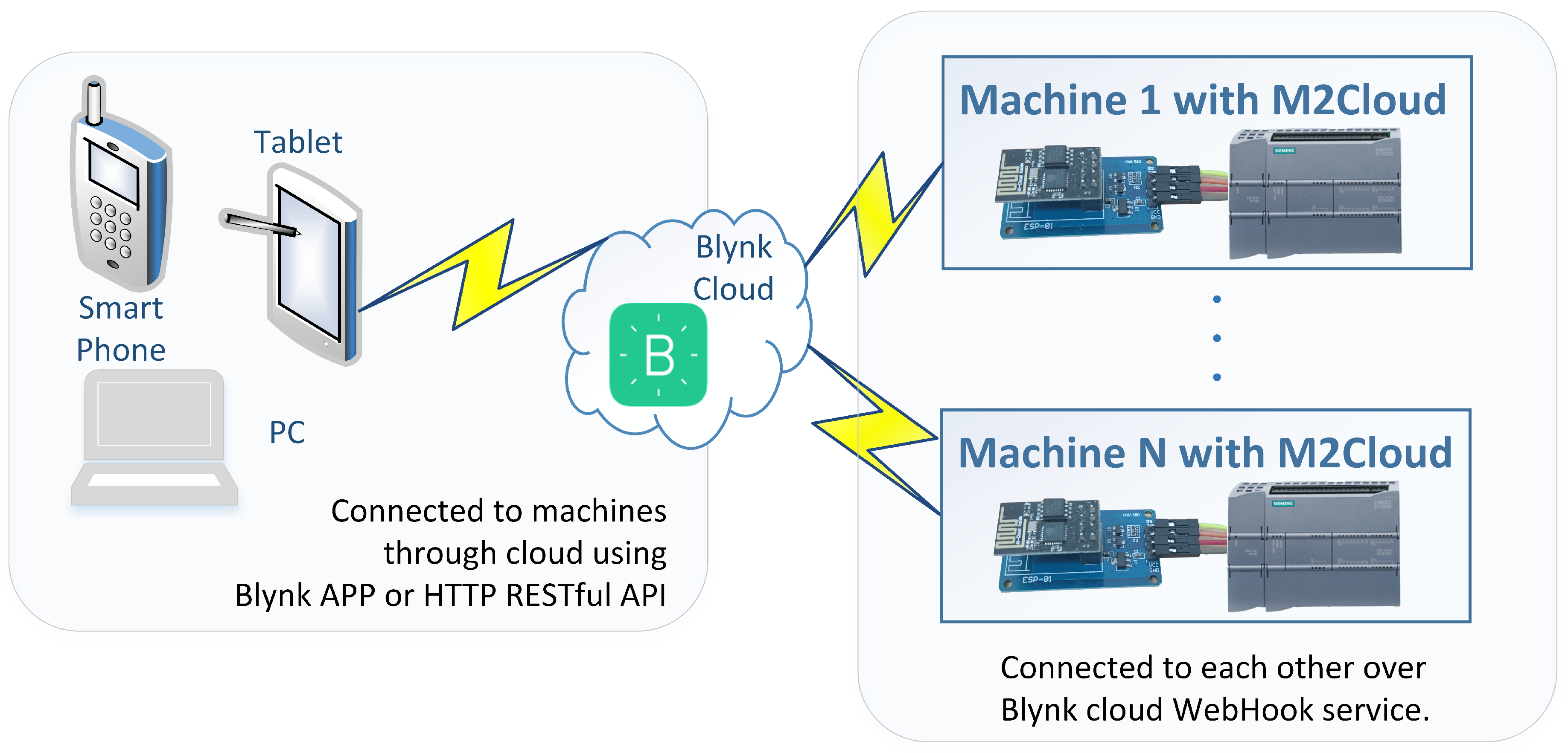
In addition to the smartphone application, the data in the cloud can be accessed through the Blynk HTTP RESTful API [30] commands, which allows any device or software having the required token to access the data in the cloud, or interconnect the data from multiple M2Cloud modules connected to diverse machines or systems through the cloud service WebHook [29]. Figure 4 illustrates the possibility of data exchange between multiple machines (systems) and users.
5. Experimental Results
When the experimental setup was assembled and the M2Cloud module connected to the machine’s control system, we conducted the experimental validation of the solution in several steps, in order to eliminate any possibility of the malfunctioning of the control system that could lead to eventual failure or hardware breakdown caused by the control system.
The first step consisted of testing the functionality of the smartphone application by testing all the controls in the smartphone application while the machine was in non-operational mode. In this step, only the PLC was operational, while the VDF was turned off; thus, the electromotor that runs the conveyor belt was not powered on. First, the variables were changed through the controls in the smartphone application, and the states of the variables were monitored on the PLC through the Siemens TIA Portal. Next, the variables were changed manually through the hardware user interface with push buttons, and the state of the variables was monitored in the smartphone application. Furthermore, a cross-validation was performed by changing the variables both on the smartphone application and the hardware user interface. The tests confirmed that the system reacted to the user commands and changed the variable values accordingly, regardless of the input device. As an example, the SPV on the hardware user interface was increased by 300 mm/s, and on the smartphone application, it was decreased by 200 mm/s at the same time; after an insignificant delay due to synchronization through the M2Cloud module, the SPV was increased by 100 mm/s. This validation step confirmed that there is no significant difference between the user control through different user interfaces.
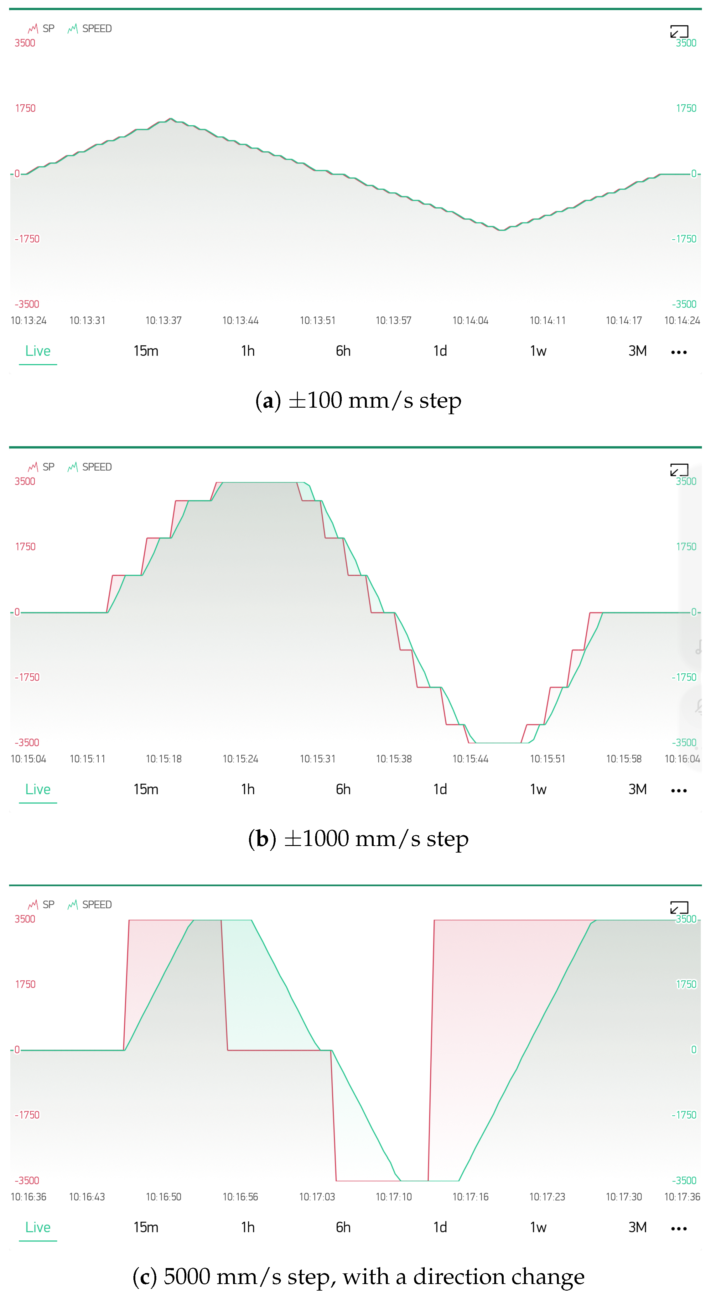
In the second step of the experimental validation, the VDF was turned on, and the system operation was tested again. First, different functions (start and stop of the conveyor belt, speed change and direction change) were tested when initiated from the hardware user interface, while the changes were monitored on the smartphone application along with the direct first-person overview of the machine. Next, the same functions were tested again, this time initiated from the smartphone application. The SPV was first changed with a step of ±100 mm/s in the ±1500 mm/s range (Figure 5a), then with a step of ±1000 mm/s in the ±3500 mm/s range (Figure 5b), and in the end, with step changes from 0 to 3500 mm/s, from 0 to −3500 mm/s, and from 3500 to −3500 mm/s (Figure 5c). This validation step confirmed that the system upgraded with the extension through the M2Cloud module still operated as expected and that the additional communication load between the PLC and the M2Cloud module did not disrupt the normal operation of the machine.
The third step of the experimental validation tested the reporting function of the developed Blynk smartphone application with a daily report for the machine operation, which was regularly received at the user’s e-mail address.
6. Conclusions
This paper presents a low-cost and easy-to-use solution that extends the traditional industrial machines and systems with IoT capabilities, thus enabling their integration into the Industry 4.0 system. The paper does not make a deep comparison with other existing solutions which are much more costly and thus financially unacceptable for the users, who often do not see a significant advantage in acquiring and storing the data for each production segment; rather, our idea was to propose a hardware that performs well enough and is as low cost as possible, to allow even machines whose interconnection will not provide direct commercial interest for the user to connect to the cloud and other machines, and thus provide valuable data acquisition, analysis, and control possibilities even in legacy systems, which are often treated as the past in developed countries, but still form the majority of industrial systems in the developing countries. The acquired data from such systems can further enable the adoption of more advanced systems for predictive maintenance, fault detection, or decision support within the system.
The proposed solution is based on a low-cost hardware module M2Cloud that can easily connect to a wide range of legacy equipment and systems and provide them with capabilities for communication with the cloud and synchronization of the desired system variables. Synchronization of the variable states with the cloud server allows continuous monitoring of all the observed variables, as well as system supervisory control from a remote location, provided that there is Internet access.
The concept of upgrading the existing control unit with an additional hardware module (M2Cloud) was chosen over developing a complete new microprocessor-based control unit [33], as this approach omits the need for lengthy functionality testing, as well as stability and reliability testing of the control system since the existing control unit already fulfills all of these requirements. The latter approach of changing the complete control system is sometimes necessary, but in general, it is justified only if the new control unit needs higher processing power or more resources for other reasons, such as upgrading the machine with vision systems or using high speed motion.
The system was designed and developed with a dedicated low-cost hardware module M2Cloud based on the ESP-01s module costing under 10 USD and a free cloud service Blynk, which allows easy integration into the IoT through a BlynkApp smartphone application. Such a low cost makes the M2Cloud acceptable even for use with machines or systems where the connection to the Internet is not necessary; however, this type of integration enables advanced possibilities for acquiring additional data and communicating with other systems, which can further be valuable for the company or the wider community. The M2Cloud module communicates with the control unit through a basic RS232 serial communication; it does not require an Ethernet connection or any higher level communication protocol; thus, it is suitable for a wide range of control units regardless of the type or manufacturer of the control unit, provided that it supports RS232 serial communication. This can be a big advantage for older PLCs or low-level control units, as even such control units usually have the RS232 communication capability, while they may not have an Ethernet connection or support higher level protocols. In addition, the firmware of the M2Cloud is independent of the type of the control unit, which makes the connection to diverse systems very easy, provided that the initial parameters are set during the first connection of the M2Cloud module to a new system. During communication, the M2Cloud module behaves as a client, which means that it responds to the commands from the control unit. Consequently, the M2Cloud does not have direct access to the data in the control unit; rather, it waits for the command for data synchronization with the cloud (read/write), which increases the system’s security by giving full control over the shared data to the control unit.
The developed system was validated on an experimental setup with a conveyor belt driven by a three-phase asynchronous electromotor controlled by a commercial PLC through a VFD. The experimental validation proved that the chosen approach of extending the system with the M2Cloud module was exceptionally efficient in using the possibilities of IoT for remote machine monitoring and control through a smartphone application, as well as for creating timely notifications and reports that can alert the user to act adequately even in unforeseen situations and events in the automated system.
At this point, the development and validation of the system concept, M2Cloud module, and the smartphone application are limited to providing the possibilities of IoT integration in a straightforward manner, without taking care of additional open privacy and security issues, which could potentially lead to undesired data leaks or intrusions into the control unit of the automated system. When using the developed concept, both the system integrator and the user must be aware of the potential risks, carefully select the data to be shared through the cloud and, if needed, additionally take care to adjust the control system to follow existing and new privacy and security standards for industrial systems.
Author Contributions
Conceptualization and methodology, L.T., I.Š., J.E.O., G.O., and S.S.; hardware and software development, L.T. and I.Š; validation, L.T., I.Š., J.E.O., G.O., and S.S.; writing, original draft preparation, L.T. and I.Š.; writing, review and editing, J.E.O., G.O., and S.S.; project administration, L.T. and G.O. All authors read and agreed to the submitted version of the manuscript.
Funding
This research was supported by the Ministry of Education, Science and Technological Development, Government of the Republic of Serbia, through the project: “Innovative scientific and artistic research from the FTN activity domain” and Grant 401-00-00589/2018-09.
Conflicts of Interest
The authors declare no conflict of interest. The funders had no role in the design of the study; in the collection, analyses, or interpretation of data; in the writing of the manuscript; nor in the decision to publish the results.
Abbreviations
The following abbreviations are used in this manuscript:
| CPS | Cyber-physical systems |
| IIoT | Industrial Internet of Things |
| IoT | Internet of Things |
| LoRa | Long range |
| LPWAN | Low-power wide-area network |
| LTE-M | Long-Term Evolution for Machines |
| M2Cloud | Machine to cloud module |
| NB-IoT | Narrowband Internet of Things |
| PLC | Programmable logic controller |
| SCADA | Supervisory Control and Data Acquisition |
| SPV | Set point velocity |
| VFD | Variable-frequency drive |
References
- Kortuem, G.; Kawsar, F.; Sundramoorthy, V.; Fitton, D. Smart objects as building blocks for the internet of things. IEEE Internet Comput. 2009, 14, 44–51. [Google Scholar] [CrossRef] [Green Version]
- Camarinha-Matos, L.M.; Goes, J.; Gomes, L.; Martins, J. Contributing to the Internet of Things. In Proceedings of the Doctoral Conference on Computing, Electrical and Industrial Systems, Costa de Caparica, Portugal, 15–17 April 2013; Springer: Berlin/Heidelberg, Germany, 2013; pp. 3–12. [Google Scholar]
- Giusto, D.; Iera, A.; Morabito, G.; Atzori, L. The Internet of Things: 20th Tyrrhenian Workshop on Digital Communications; Springer Science & Business Media: Berlin/Heidelberg, Germany, 2010. [Google Scholar] [CrossRef]
- Atzori, L.; Iera, A.; Morabito, G. The Internet of Things: A survey. Comput. Netw. 2010, 54, 2787–2805. [Google Scholar] [CrossRef]
- ITU-T. Recommendation ITU-T Y.2060: Overview of the Internet of Things; The International Telecommunication Union—Telecommunication Standardization Sector (ITU-T): Geneva, Switzerland, 2013. [Google Scholar]
- Techtrol, P. IIoT and Automation. Available online: https://www.punetechtrol.com/blogs/iiot-and-automation (accessed on 10 August 2019).
- Hermann, M.; Pentek, T.; Otto, B. Design Principles for Industrie 4.0 Scenarios. In Proceedings of the 2016 49th Hawaii International Conference on System Sciences (HICSS), Koloa, HI, USA, 5–8 January 2016; pp. 3928–3937. [Google Scholar] [CrossRef] [Green Version]
- Lasi, H.; Fettke, P.; Kemper, H.G.; Feld, T.; Hoffmann, M. Industry 4.0. Bus. Inf. Syst. Eng. 2014, 6, 239–242. [Google Scholar] [CrossRef]
- Vaidya, S.; Ambad, P.; Bhosle, S. Industry 4.0—A glimpse. Procedia Manuf. 2018, 20, 233–238. [Google Scholar] [CrossRef]
- Todorović, V.; Lazarević, M. RFID Based System Usage in Process of Liquid Product Tracking. J. Mechatron. Autom. Identif. Technol. 2018, 3, 26–29. [Google Scholar]
- Markov, M.; Stankovski, S.; Ostojić, G.; Baranovski, I.; Horvat, S. Application of Firebase Cloud Service for Storing and Analyzing Data from IoT Mobile Devices. J. Mech. Autom. Identif. Technol. 2018, 3, 17–20. [Google Scholar]
- Hozdić, E.; Kozjek, D.; Butala, P. A Cyber-Physical Approach to the Management and Control of Manufacturing Systems. Strojniški Vestnik/J. Mech. Eng. 2020, 66, 61–70. [Google Scholar] [CrossRef]
- Herakovič, N.; Zupan, H.; Pipan, M.; Protner, J.; Šimic, M.; Herakovič, N.; Protner, H.Z.M.P.J.; Šimic, M. Distributed Manufacturing Systems with Digital Agents. Strojniski Vestnik/J. Mech. Eng. 2019, 65, 650–657. [Google Scholar] [CrossRef] [Green Version]
- Givehchi, O.; Landsdorf, K.; Simoens, P.; Colombo, A.W. Interoperability for industrial cyber-physical systems: An approach for legacy systems. IEEE Trans. Ind. Inform. 2017, 13, 3370–3378. [Google Scholar] [CrossRef]
- Park, H.M.; Jeon, J.W. OPC UA based Universal Edge Gateway for Legacy Equipment. In Proceedings of the 2019 IEEE 17th International Conference on Industrial Informatics (INDIN), Helsinki, Finland, 22–25 July 2019; Volume 1, pp. 1002–1007. [Google Scholar]
- Toc, S.I.; Korodi, A. Modbus-OPC UA Wrapper using Node-RED and IoT-2040 with application in the water industry. In Proceedings of the 2018 IEEE 16th International Symposium on Intelligent Systems and Informatics (SISY), Subotica, Serbia, 13–15 September 2018; pp. 000099–000104. [Google Scholar]
- Trancă, D.C.; Pălăcean, A.V.; Mihu, A.C.; Rosner, D. ZigBee based wireless modbus aggregator for intelligent industrial facilities. In Proceedings of the 2017 25th Telecommunication Forum (TELFOR), Belgrade, Serbia, 21–22 November 2017; pp. 1–4. [Google Scholar]
- Patnaik Patnaikuni, D.R. A Comparative Study of Arduino, Raspberry Pi and ESP8266 as IoT Development Board. Int. J. Adv. Res. Comput. Sci. 2017, 8, 2350–2352. [Google Scholar]
- Leonardi, L.; Battaglia, F.; Bello, L.L. RT-LoRa: A medium access strategy to support real-time flows over LoRa-based networks for industrial IoT applications. IEEE Internet Things J. 2019, 6, 10812–10823. [Google Scholar] [CrossRef]
- Huo, Y.; Dong, X.; Lu, T.; Xu, W.; Yuen, M. Distributed and multilayer UAV networks for next-generation wireless communication and power transfer: A feasibility study. IEEE Internet Things J. 2019, 6, 7103–7115. [Google Scholar] [CrossRef]
- Huo, Y.; Dong, X.; Beatty, S. Cellular Communications in Ocean Waves for Maritime Internet of Things. IEEE Internet Things J. 2020. [Google Scholar] [CrossRef] [Green Version]
- Borkar, S.R. Long-term evolution for machines (LTE-M). In LPWAN Technologies for IoT and M2M Applications; Academic Press: Cambridge, MA, USA, 2020; pp. 145–166. [Google Scholar]
- Tarjan, L.; Tejić, B.; Dragičević, D.; Ostojić, G.; Đukić, N. An alternative communication possibility during a natural disaster by using lowpower long-range RF modules. In Proceedings of the 2018 17th International Symposium INFOTEH-JAHORINA (INFOTEH), East Sarajevo, Bosnia and Herzegovina, 21–23 March 2018; pp. 1–6. [Google Scholar]
- Kajan, M.; Šovčik, J.; Duchoň, F.; Mrafko, L.; Florek, M.; Beňo, P. Sensoric subsystem of automated guided vehicle: TCP communication between SIMATIC S7 PLC and Arduino. In Proceedings of the 2014 23rd International Conference on Robotics in Alpe-Adria-Danube Region (RAAD), Smolenice, Slovakia, 3–5 September 2014; pp. 1–6. [Google Scholar]
- González, I.; Calderón, A.J. Integration of open source hardware Arduino platform in automation systems applied to Smart Grids/Micro-Grids. Sustain. Energy Technol. Assess. 2019, 36, 100557. [Google Scholar] [CrossRef]
- Mageshkumar, G.; Kasthuri, N.; Tamilselvan, K.; Suthagar, S.; Sharmila, A. Design of Industrial Data Monitoring Device Using IoT Through MODBUS Protocol. Int. J. Sci. Technol. Res. 2020, 9, 1392–1396. [Google Scholar]
- Industrial Shields: How Connect Arduino Based PLC with Siemens PLC Equipped with Ethernet Port. Available online: http://blog.industrialshields.com/en/how-connect-arduino-based-plc-with-siemens-plc-equipped-with-ethernet-port/ (accessed on 15 July 2020).
- Nardella, D. Settimono: ARDUINO Ethernet Communication Library for S7 Siemens PLC. 2019. Available online: http://settimino.sourceforge.net/ (accessed on 15 July 2020).
- Get Started with Blynk in 5 min. Available online: https://blynk.io/en/getting-started (accessed on 1 September 2019).
- Blynk HTTP RESTful API. Available online: https://blynkapi.docs.apiary.io/# (accessed on 1 September 2019).
- Martinović, A.; Tarjan, L.; Šenk, I.; Tegeltija, S.; Stankovski, S.; Ostojić, G. A Blynk based system for remote process monitoring and control. In Proceedings of the 5th Conference & Workshop Mechatronics in Practice and Education (MECHEDU), Subotica, Serbia, 12 December 2019; Subotica Tech-College of Applied Sciences: Subotica, Serbia, 2019. [Google Scholar]
- Wang, H.; He, W.; Wang, F.K. Enterprise cloud service architectures. Inf. Technol. Manag. 2012, 13, 445–454. [Google Scholar] [CrossRef]
- Ghassoul, M.; Ebrahim, H.H.; Yusuf, F.A.H. A Microcontroller-Based Remote Embedded SCADA Control System With the Aid of a 32-Bit Microcontroller. Am. J. Embed. Syst. Appl. 2019, 7, 9–20. [Google Scholar] [CrossRef] [Green Version]
Figure 1.
Block diagram of connecting the M2Cloud module.

Figure 2.
The experimental setup used for validation.

Figure 3.
Smartphone application for machine monitoring and control.

Figure 4.
Connecting multiple devices through the cloud.

Figure 5.
Plots from the smartphone application with different SPV changes.


Table 1.
Current market prices of commercially available serial to LAN and serial to WLAN modules.
| Serial to LAN | Price (USD) | Serial to WLAN | Price (USD) |
|---|---|---|---|
| Xeta Server | 59.75 | Antratek Serial to WLAN converter | 113.40 |
| Antratek RS232 Ethernet Converter | 62.46 | NetCom 123 WLAN | 193.05 |
| DigiTech Serial to Ethernet | 189.95 | Process-Informatik Wireless around the | 349.83 |
| Converter XC4134 | ProfiNet-PLC, Schneider-PLC | ||
| Westermo EDW-100 Serial | 450.09 | Process-Informatik Wireless | 816.66 |
| to Ethernet converter | around the S7-PLC |
Table 2.
Current market prices of M2Cloud module components.
| Component | Price (USD) |
|---|---|
| ESP8266 ESP-01 WiFi Module | 1.12 |
| HW-580 ESP-01 to Serial Adapter Module 3.3V <> 5V | 0.58 |
| MAX3232 RS232 to TTL Serial Port Converter | 0.46 |
| DC-DC Step Down LM2596 DC 4.0–40 V to 1.3–37 V Adjustable Voltage Regulator | 0.84 |
| Electronic Project Case—DINRail Fire-Resistant Plastic | 3.49 |
| Total | 6.49 |
© 2020 by the authors. Licensee MDPI, Basel, Switzerland. This article is an open access article distributed under the terms and conditions of the Creative Commons Attribution (CC BY) license (http://creativecommons.org/licenses/by/4.0/).
Share and Cite
MDPI and ACS Style
Tarjan, L.; Šenk, I.; Erić Obućina, J.; Stankovski, S.; Ostojić, G. Extending Legacy Industrial Machines by a Low-Cost Easy-to-Use IoT Module for Data Acquisition. Symmetry 2020, 12, 1486. https://doi.org/10.3390/sym12091486
AMA Style
Tarjan L, Šenk I, Erić Obućina J, Stankovski S, Ostojić G. Extending Legacy Industrial Machines by a Low-Cost Easy-to-Use IoT Module for Data Acquisition. Symmetry. 2020; 12(9):1486. https://doi.org/10.3390/sym12091486
Chicago/Turabian StyleTarjan, Laslo, Ivana Šenk, Jelena Erić Obućina, Stevan Stankovski, and Gordana Ostojić. 2020. "Extending Legacy Industrial Machines by a Low-Cost Easy-to-Use IoT Module for Data Acquisition" Symmetry 12, no. 9: 1486. https://doi.org/10.3390/sym12091486
Note that from the first issue of 2016, this journal uses article numbers instead of page numbers. See further details here.