Adaptive Sliding Mode Control Based on Disturbance Observer for Placement Pressure Control System


School of Mechanical Engineering, Northwestern Polytechnical University, Xi’an 710072, China
*
Author to whom correspondence should be addressed.
Symmetry 2020, 12(6), 1057; https://doi.org/10.3390/sym12061057
Submission received: 15 May 2020
/
Revised: 10 June 2020
/
Accepted: 22 June 2020
/
Published: 26 June 2020
Abstract
:In the process of composite placement, irregularity and asymmetry pressure fluctuation will affect the density and evenness of composite products, which lead to the inconsistency of interfacial strength and fiber volume fraction. The dynamic performance of placement pressure systems will be affected by external disturbance, mechanism friction and measurement noise. In this paper, an adaptive sliding mode control (ASMC) strategy based on disturbance observer (DOB) is proposed. The disturbance observer is introduced to estimate the equivalent disturbance torque, and the estimation error is compensated by the switching term of sliding mode control. The adaptive method is used to ensure that the switching gain is not overestimated, and then the Lyapunov function is used to verify the stability of the closed-loop control system. The experimental results and simulation analysis show that ASMC-DOB has high control accuracy and good robustness. At the same time, the designed algorithm can effectively reduce the void content of composite products.
1. Introduction
Composite materials have a series of advantages, such as being light weight, anti-fatigue, having corrosion resistance, high modulus, high strength and strong designability, and have been widely used in many industrial fields, especially in large-scale integral structure and aviation components [1,2,3,4,5,6,7]. Composite tape placement technology is one of the common methods in the composite forming process. The final properties of composite products are very sensitive to parameters. The performance of composite products is directly related to the selection and control accuracy of parameters such as placement temperature, pressure and speed. Placement pressure is an important parameter of the composite tape placement forming process. Choosing an appropriate pressure interval value and having an excellent pressure control system can improve resin content and homogeneity of placement products, reduce void content and enhance density [8,9,10].
From the perspective of the control algorithm, the pressure control system of composite material placement equipment is complex, nonlinear and easy to be disturbed, which makes the mathematical modeling of the control system and the design of the controller more difficult. Due to the simple algorithm, good robustness and high reliability, Proportion Integral Differential (PID) is widely used in industrial process control. However, due to the nonlinearity, time varying uncertainty, strong disturbance and badness of parameter adjusting performance, it is difficult to achieve the ideal control effect by using the conventional PID controller in actual working condition [11,12,13,14]. Sliding mode control can overcome the uncertainty of the system, has strong robustness to disturbance and unmodeled dynamics and has good control effect on the nonlinear system. High frequency chattering of sliding mode control brings many adverse effects, such as damaging the sensor, exciting the unmodeled dynamic characteristics of the system, and influencing the control system structure [15,16,17,18,19,20]. The approaching laws and boundary layer method are applied to reduce chattering, which leads to less control accuracy [21,22,23].
In the last few years, many researchers combine intelligent control technology with Sliding Mode Control (SMC). In literature [24], in order to improve the robustness of the control system, the adaptive linear neural network is introduced into the traditional sliding mode observer, and the radial basis function is constructed to approximate the equivalent control law. In literature [25], an adaptive fuzzy sliding mode controller with nonlinear observer is proposed, and adaptive fuzzy logic is designed to approximate the parameters of sliding mode controller, which can effectively avoid high frequency chattering. An adaptive controller based on function approximation technology is used to learn unknown dynamics, and Fourier series is used to deal with external uncertainty to realize speed tracking [26]. In literature [27], by updating the Fourier coefficient, the time-varying and disturbance in the Fourier series can be estimated. A mode compensated adaptive backstepping sliding mode controller is proposed to suppress chattering.
In this manuscript, the pressure control system is analyzed and the dynamic model is established. Adaptive sliding mode control strategy based on disturbance observer (ASMC-DOB) is designed to improve the control accuracy of systems with mismatched uncertainties, which SMC algorithm can’t overcome very well [28,29]. Simulation and experimental results show that the designed algorithm can significantly improve the control accuracy and effectively suppress chattering.
2. Calculation Model of Placement Pressure
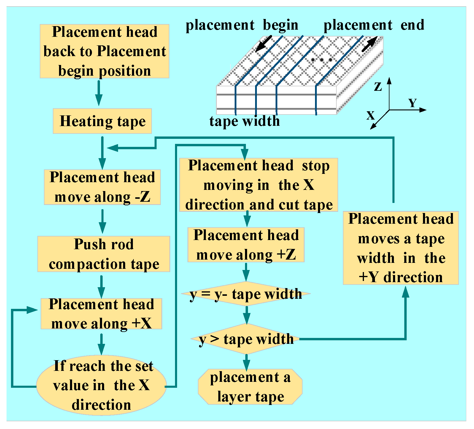
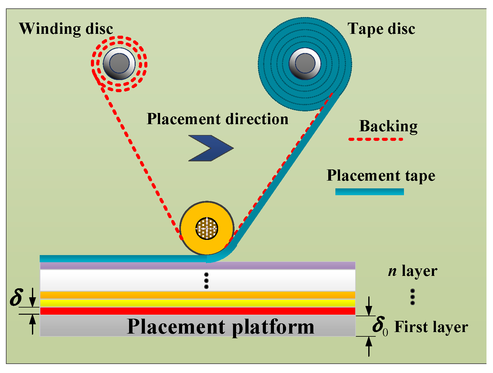
To realize the placement function, the placement head must be able to move and rotate freely in three-dimensional space, the placement flow chart is shown in Figure 1. Schematic of composite laminate is shown in Figure 2, the thickness of each composite laminate is equal, the stress of each composite laminate can be expressed as follows:
where is thickness of composite laminate, is initial stress of prepreg, is elastic modulus of placement platform, is elastic modulus of prepreg, is placement pressure of composite laminate, is equivalent thickness of composite laminate, is thickness of placement platform and is stress of composite laminate.
In order to ensure that the initial stress of each composite laminate is equal, the placement pressure value is time-varying. If , , , then,
Placement pressure of the j composite laminate can be represented by placement pressure of outermost composite laminate . can be expressed as follows:
According to Equations (1) and (2), then,
Substituting Equation (5) into Equation (4), pressure calculation model can be expressed as follows:
Equation (6) is the calculation model of placement pressure, which shows that the application of pressure value in the machine process is time-varying. The traditional constant pressure placement process cannot guarantee the excellent performance of composite products. Therefore, we carry out variable pressure placement processing, which requires higher robustness, dynamic characteristics and control accuracy of the controller.
3. Establishing Mathematical Model of Placement Pressure Control System
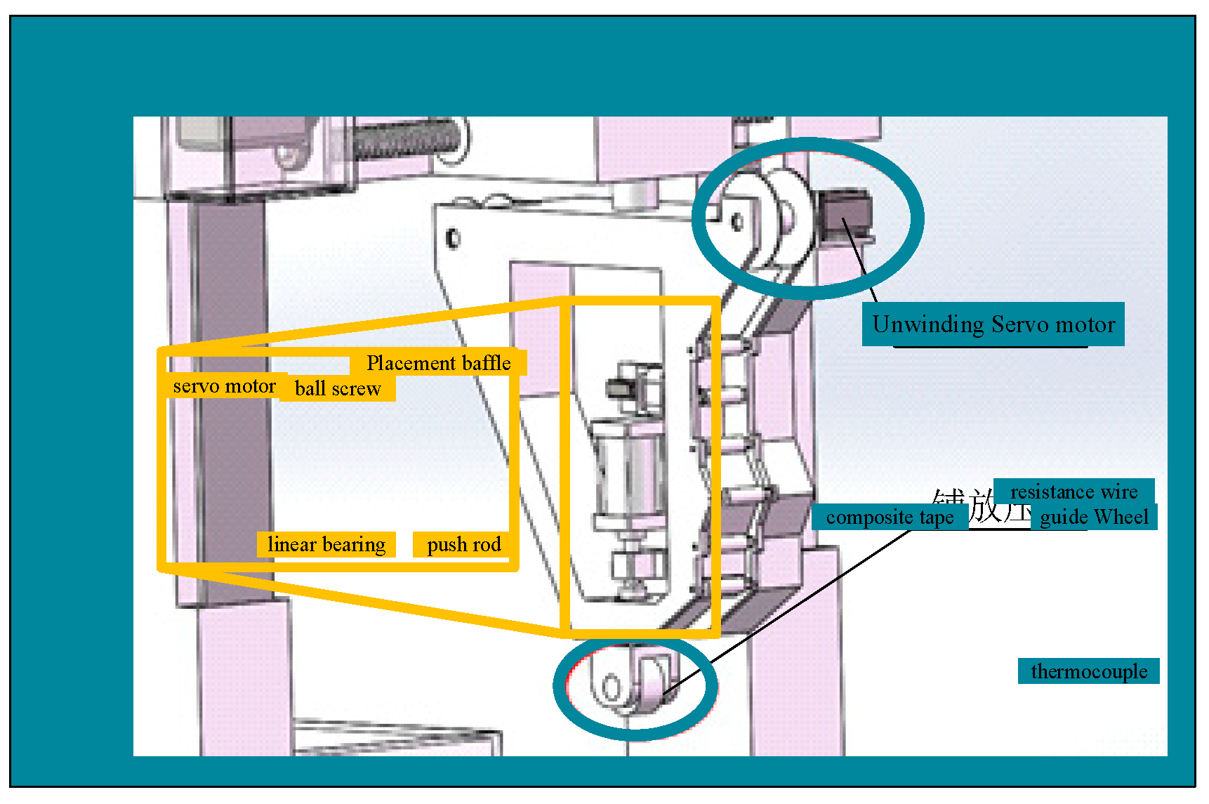
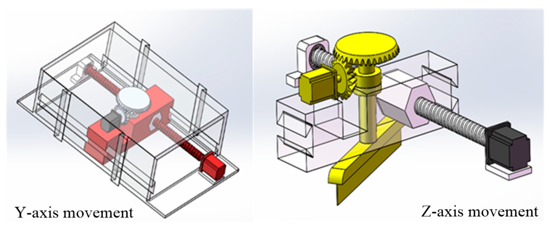
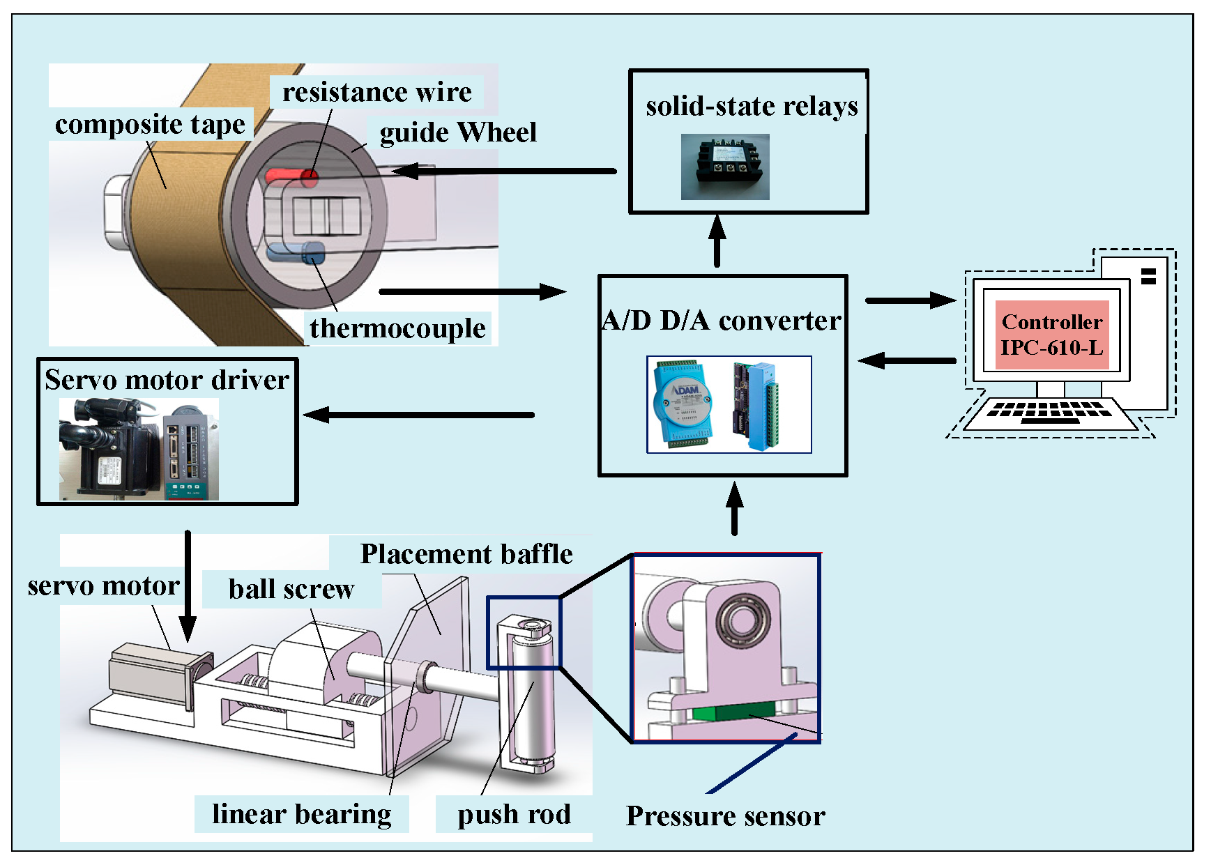
The overall structure of the placement machine adopts the gantry type, the placement head is assembled on the gantry frame and the worktable is placed under the placement head. The movement of the screw is controlled by a servo motor to apply placement pressure. Due to the advantages of good controllability, high stability and high-speed response, the servo motor is suitable for high-precision control conditions. The composite tape is heated to make the resin melt to produce better viscosity in the placement process, which can make the layers better combined. The structure of the heating device and the pressure actuator are shown in Figure 3. To ensure the cutting edge of the tape is complete and smooth with better shearing quality, the designed tape cutting mechanism is shown in Figure 4. The cutting tape actuator is mainly composed of two servo motors and a cylinder. The placement pressure control process is shown in Figure 5. In order to facilitate the establishment of the mathematical model, core hysteresis and eddy current loss are ignored. According to Kirchhoff’s law, voltage equation of motor winding can be expressed as follows:
where is motor resistance, , and are motor winding voltage, , and are motor winding current, , and are induced electromotive force and , and winding inductance.
Winding inductance is constant L and mutual inductance is ignored. Then, Equation (7) can be simplified as follows:
When the motor adopts the star connection method, induced electromotive force is as follows:
where and are pole pairs of motor, motor speed, pole arc coefficient, turns-in-series and magnetic flux, respectively.
According to the motor characteristics, motor output torque can be written as follows:
where and are motor current, motor angular speed and motor output torque, respectively. According to Equations (9) and (10), Equation (11) can be obtained:
The mathematical relationship between the electromagnetic torque and screw torque can be expressed as follows:
where is motor moment of inertia, is equivalent torque of screw and is motor damping coefficient.
Equation (12) can be expressed as follows:
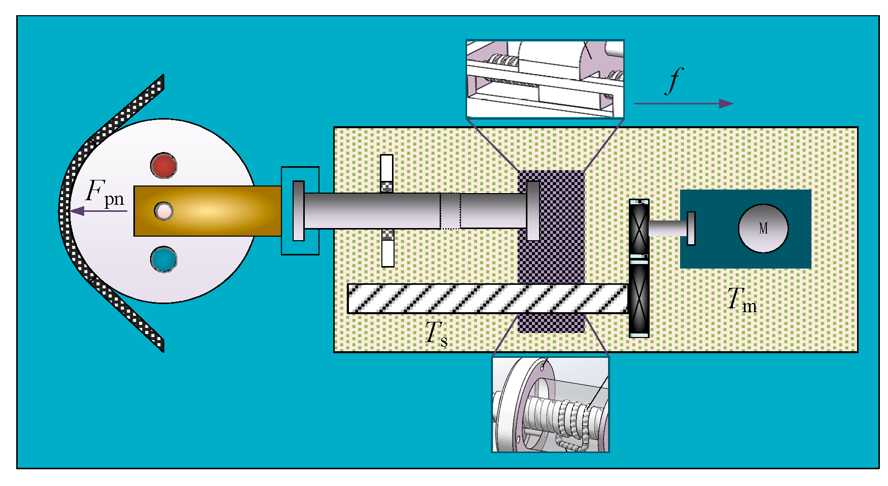
According Figure 6, the equilibrium equation of screw torque is as follows:
where Fpn is placement pressure, is the angle between winding tension and screw load,, and are screw moment of inertia, screw damping coefficient and screw load, respectively.
Friction between dovetail groove and worktable is as follows:
where is friction between dovetail groove and worktable, is dovetail groove slope angle, is worktable mass and is friction coefficient.
The relationship between feed speed and the rotation angle of screw can be written as follows:
According Equation (17), then derivative:
According Equations (14), (16) and (18), Equation (19) can be obtained:
Substitute Equation (19) into Equation (13), then,
4. DOB-Based ASMC
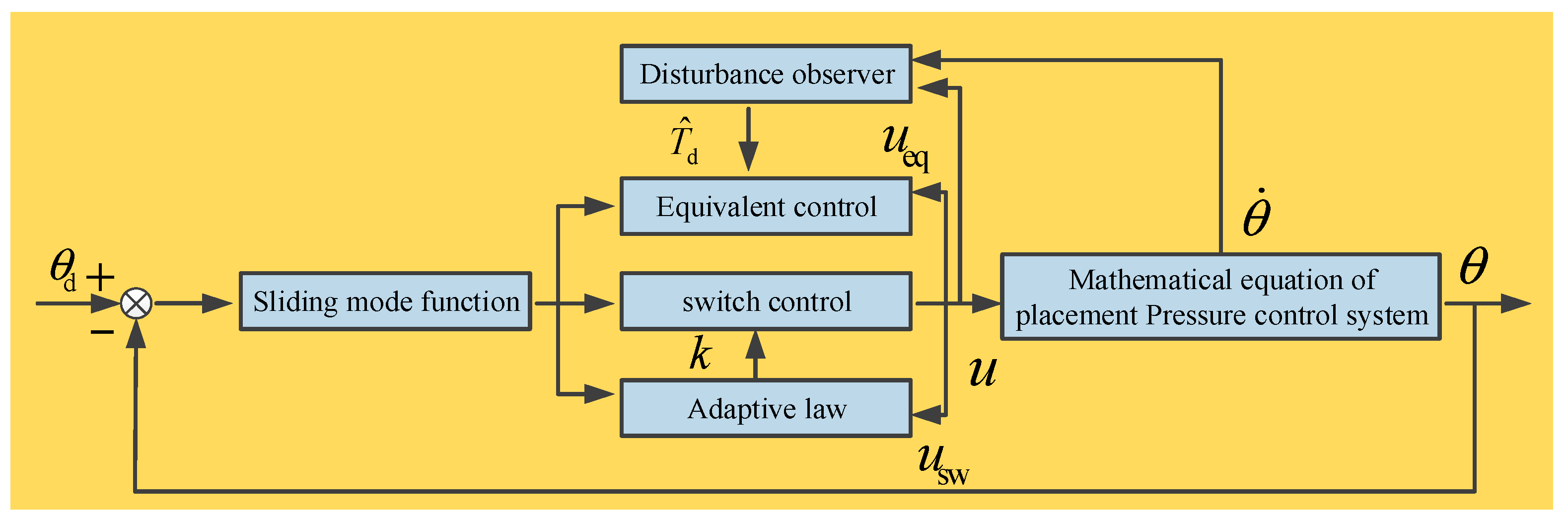
The structure of ASMC-DOB is shown in Figure 7 , and are position reference signal, actual position output and disturbance observer output, respectively. Its control objective is to quickly overcome the parameter change, uncertainty and nonlinear friction of the system, ensure that tracks and keep the tracking error as small as possible.
4.1. Design of Sliding Mode Controller
Position tracking error can be defined as follows:
Integral type sliding mode function can be expressed as follows:
where is switching surface adjustable parameter and .
Without considering the unknown disturbance, control system model is as follows:
Suppose , according Equations (21)–(23), equivalent control law can be written as follows:
Due to the uncertainty and external interference of the system, the combination of equivalent control and switching control is applied, then,
where is switching gain, .
Substitute Equation (24) into Equation (25), then the system control law can be written as follows:
To verify the stability of the system, positive definite Lyapunov function is selected.
By differentiating Equation (27), according Equations (26) and (22), then
When , , the system is stable.
4.2. Design of Disturbance Observer
Parameter uncertainty and nonlinear friction are included by . If switch control item compensation is adopted directly, it will lead to strong chattering of the system and oscillation of control signal. Disturbance observer and gain adaptive law are proposed to improve the algorithm. The disturbance observer is mainly used to reduce the switch item amplitude, and gain adaptive law is used to solve the unknown upper bound of disturbance and reduce the chattering of the system.
Disturbance observer can be defined as follows:
where is the gain of disturbance observer and is the estimated disturbance torque.
By introducing auxiliary variable and , then,
The observation error of disturbance observer can be defined as follows:
Substitute Equation (30) into Equation (31), then derivative,
Supposing the system disturbance changes slowly, if , , the disturbance error can be guaranteed to converge exponentially. After the disturbance observer is introduced, the control law of the system can be expressed as follows:
To verify the stability of the system, positive definite Lyapunov function is introduced.
When , , the system is stable.
4.3. Design of Gain Adaptive Law
When the state trajectory reaches the sliding mode surface, it is difficult to slide strictly along the sliding mode towards the equilibrium point, but it passes through the equilibrium point back and forth on both sides. In this paper, the following gain adaptive law is adopted.
where , and . The larger is, the larger the lower bound of is, and the larger the switching amplitude is, which leads to system instability. should be as small as possible, but to ensure the stability of the closed-loop system.
According Equations (30) and (34), the gain of the switching term is bounded, supposing the normal number always exists. Proof define positive definite Lyapunov function is as follows:
Then,
By introducing parameter , then,
Equation (38) is simplified as follows:
where .
Condition 1, if , , then, , which ensures the stability of the closed-loop system. Condition 2, when , sign of cannot be determined, and the stability of the Lyapunov function cannot be guaranteed. But if does not remain, then back to condition 1. According to the above analysis, the proposed adaptive sliding mode control algorithm based on disturbance observer is stable.
5. Simulation Analysis and Experimental Verification
5.1. Simulation Analysis
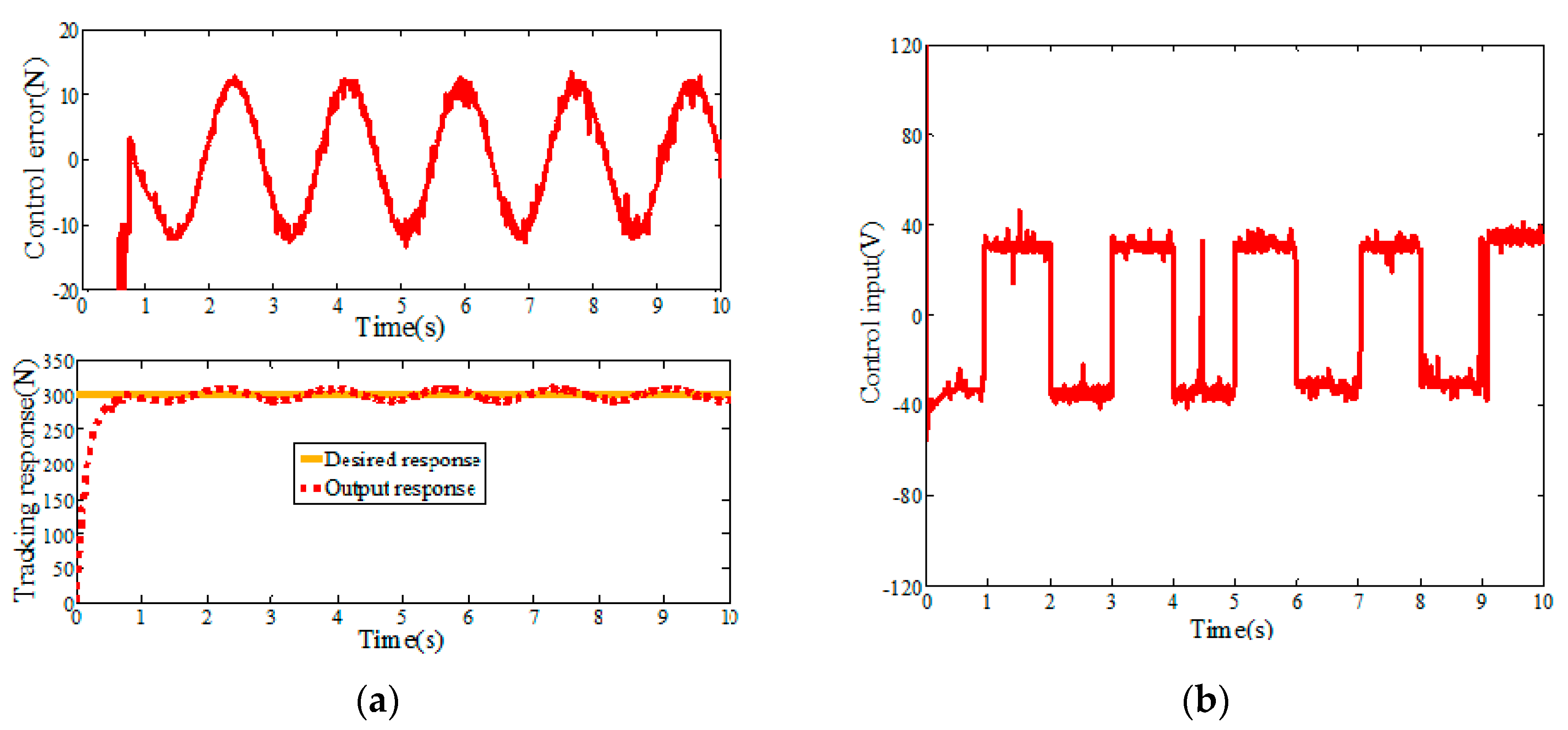
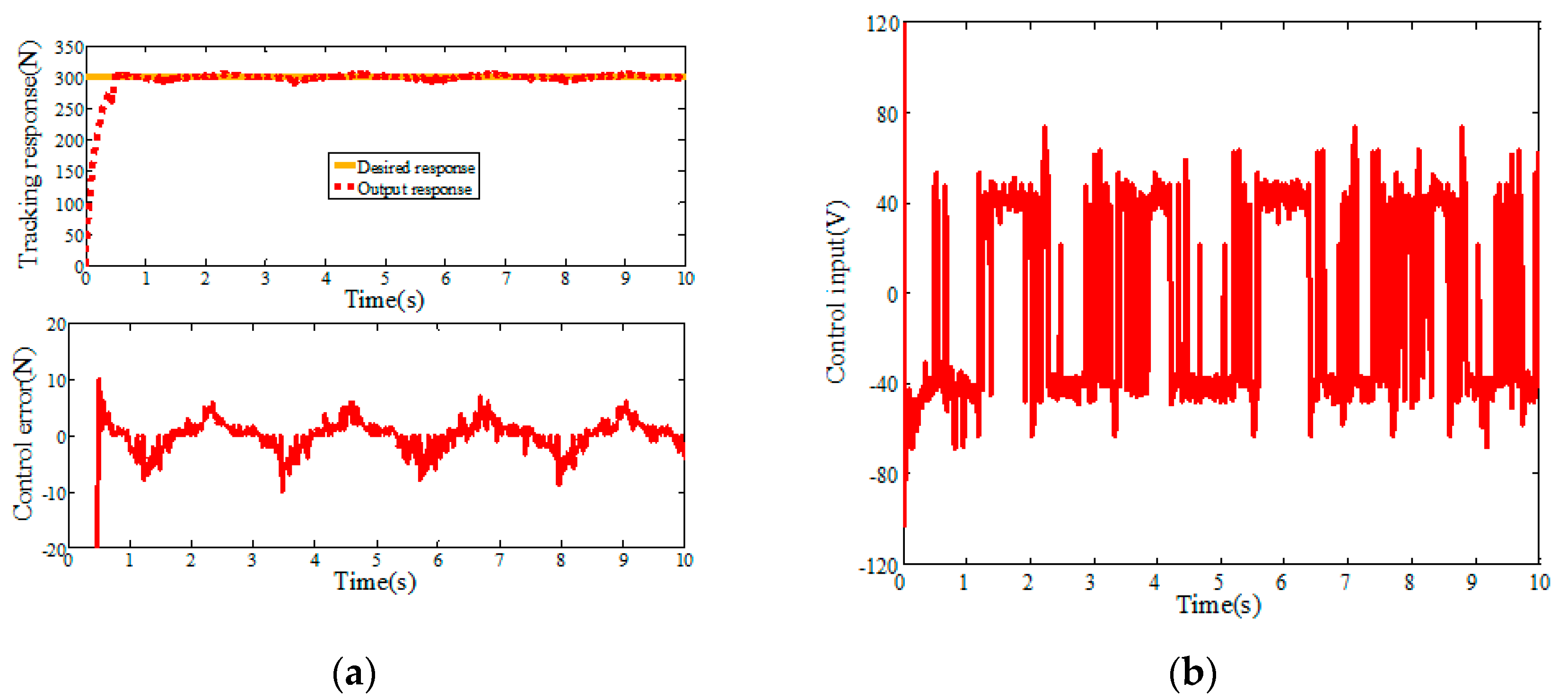
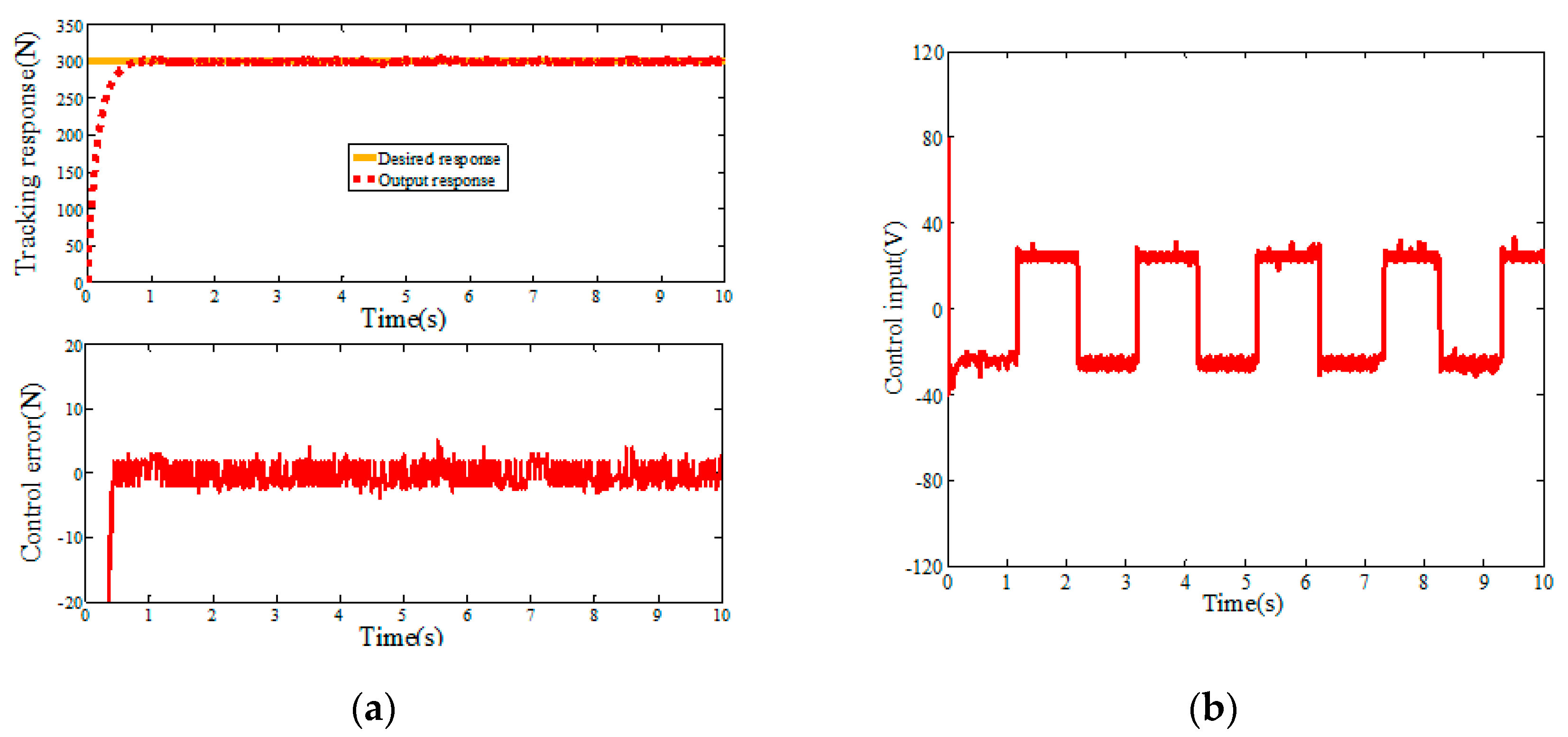
In order to verify the effectiveness of the ASMC-DOB algorithm, the hardware-in-the-loop simulation experiment is carried out, and the mathematical model of the placement pressure control system is taken as the controlled object. A step signal (r1(t) = 300 N) is used for positioning control, and relevant parameters of placement pressure control system are shown in Table 1. The simulation results of step response are shown in Figure 8, Figure 9 and Figure 10. Figure 8 and Figure 9 are the step response simulation results of PID and SMC, respectively. The control error of PID step response and SMC step response are 12.58 N and 6.28 N, respectively. The SMC algorithm has strong robustness and can effectively reduce the control error compared with the PID algorithm. However, it can be seen in Figure 9 that the sliding mode control has large high-frequency chattering, which will affect the system structure and damage the sensor. In order to reduce the high frequency chattering of the control input, the ASMC-DOB control algorithm is proposed. Figure 10 shows that the control error is 3.46 N. Compared PID and SMC, the control error of the design ASMC-DOB is reduced by 72.5%, and 41.3%, respectively.
It can be seen from the simulation results that the PID algorithm has the largest control error. Compared with the PID algorithm, SMC can effectively reduce the control error, but the control input chattering is sharply increased. The DOB-based ASMC algorithm proposed satisfies the tension control system with both smaller control input chattering and smaller control error.
5.2. Experimental Verification
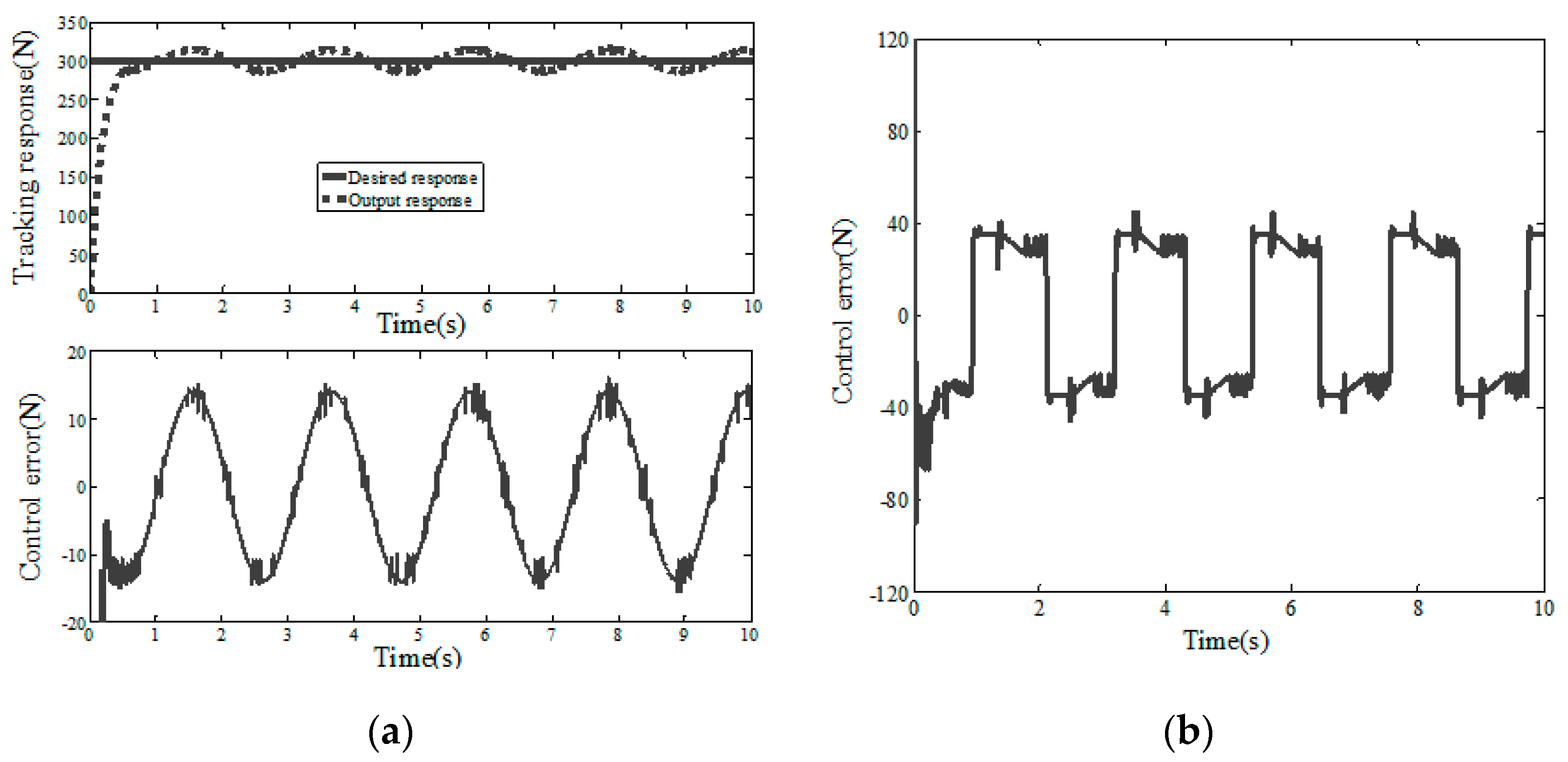
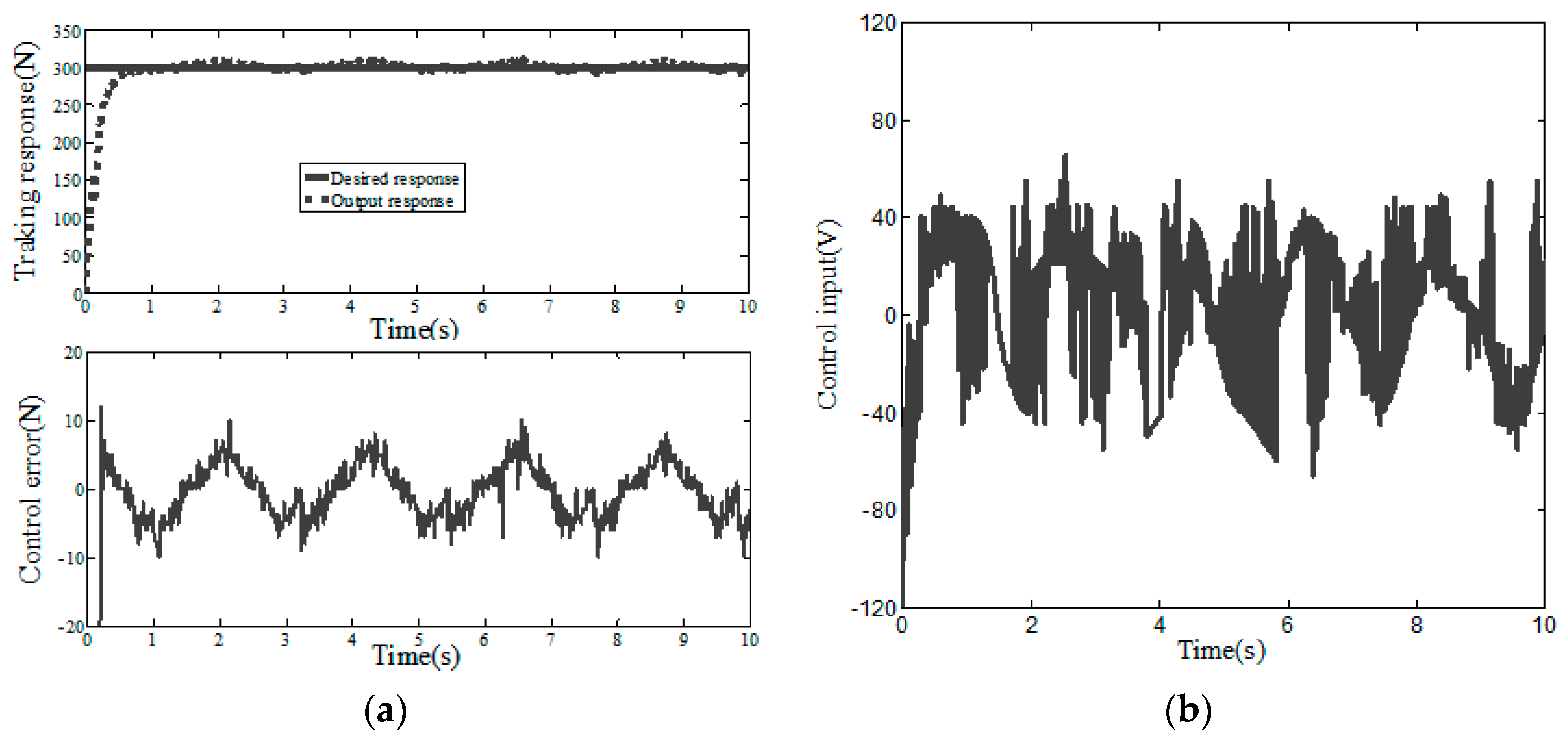
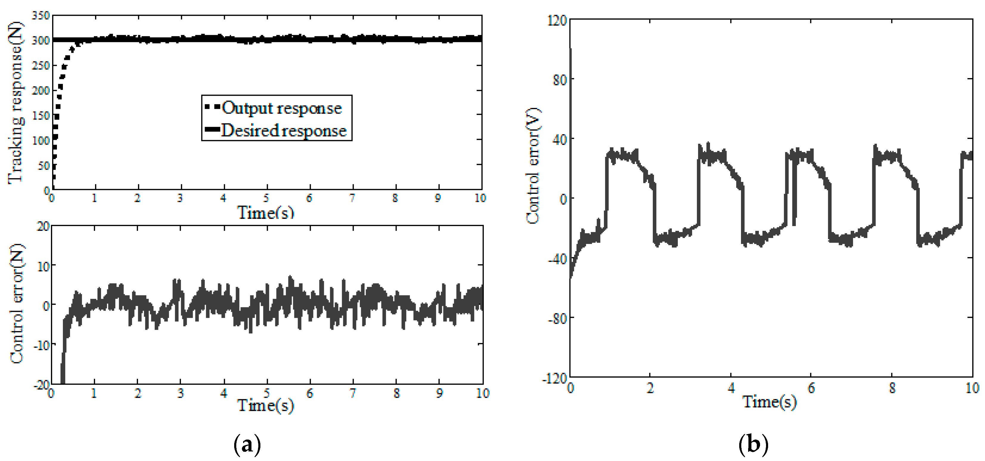
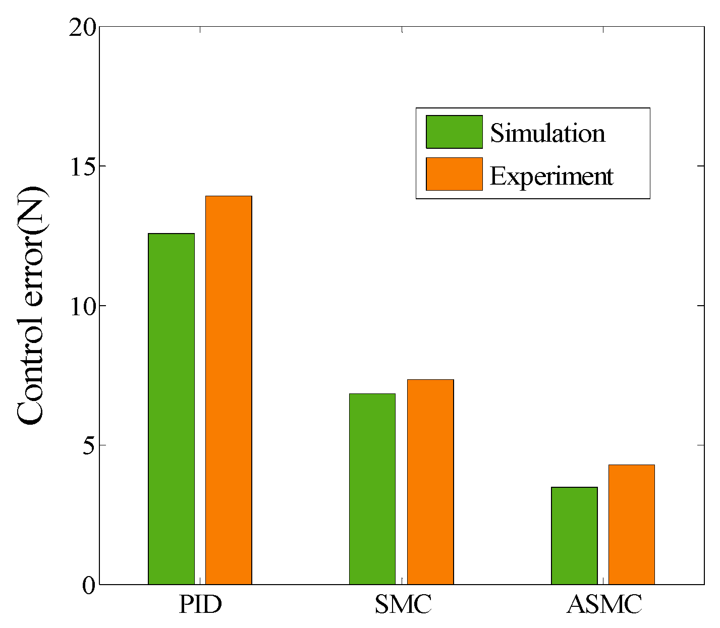
In this experiment, IPC-610-L is used as the controller carrier, and C++ is used to write the experimental program. The designed control programs include sampling, pressure sensor measurement function and digital and analog signal conversion. A digital I/O card (PCL-730), Advantech 2-way isolated analog output card (PCI-728) and data acquisition card (PCI-1680U) are used for conversion, acquisition and data output, respectively. The experiment is carried out on CH#2 composite tape placement equipment. The experimental results are shown in Figure 11, Figure 12 and Figure 13, and the simulation and experimental results have the same trend. It can be seen from Table 2 and Figure 14 that ASMC-DOB control input chattering and control error are smaller than PID and SMC, and the ASMC-DOB reduces the control errors of step response by 41.7% and 69.2%, respectively.
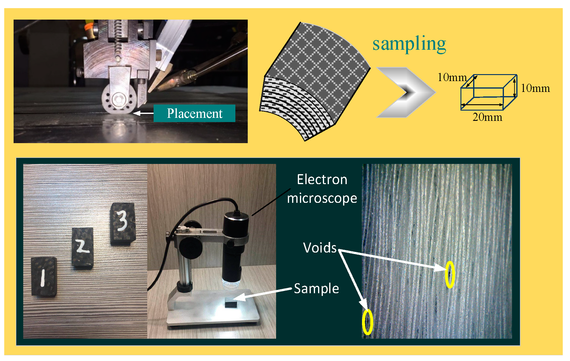
In order to further verify the effectiveness and feasibility of ASMC-DOB, different control algorithms were used to carry out the placement experiment, and observation of the change of void content of composite products. Void content is an important index to measure the product’s mechanical properties. There are many ways to measure void content, such as density measurements by microscopy [30,31,32,33,34,35,36,37], detection method of ultrasonic attenuation [38] and computed tomography, which can also be performed using X-rays [39]. In GB/T3365-2008 [40], an electron microphotography method is proposed, which provides the highest void content detection accuracy. Sampling and void content measurement processes are shown in Figure 15. The samples are polished and ground under flowing water, and then observed by microscope.
According to Equation (40), the void content can be easily obtained.
where is the void content, is the total void area and is a cross section of the sample.
Three different algorithms are used for the laying experiment, and Table 3 shows the change trend of void content of composite products. It is known that the designed ASMC has reduced the void content by about 75.8% and 59.5%, when compared with the PID and SMC. Experimental results show that the ASMC algorithm can reduce the void content of composite placement products. Reduced void content of composite products can reflect the improvement of stability and control accuracy of placement pressure systems.
6. Conclusions
In this paper, a calculation model of placement layer pressure is established and analyzed, and it is determined that the pressure should be time-varying. Variable pressure machining can better guarantee the product’s mechanical properties, and at the same time, it needs to ensure that the controller has better dynamic performance and higher control accuracy.
Sliding mode control has many advantages, such as strong robustness to disturbances and unmodeled dynamics, insensitivity to parameter changes and disturbances, fast response and simple physical implementation, so it is suitable for servo system. However, due to the characteristics of SMC discontinuity switch, the system will chatter at high frequency which affects the control accuracy and makes the system oscillate and unstable. In order to ensure the stability and high control accuracy of the placement pressure control system, a robust control algorithm ASMC-DOB is proposed. The disturbance observer can accurately estimate the external disturbance in finite time, compensate the system input, improve the control accuracy and reduce chattering. The parameters vary with the state variables using the proposed method, which improves the dynamic performance of the system and reduces the control input.
Experimental and simulation results show that ASMC-DOB has stronger interference suppression, robustness, smaller control error and the highest control precision when compared with PID and SMC. ASMC-DOB can also effectively improve the consistency, stability and other properties of composite placement products.
Author Contributions
Q.H. performed the experiments, wrote the manuscript and analyzed the data; Y.S. designed the experimental process and guided the direction of the research; Z.C. assist in the experimental process and data analysis. All authors have read and agreed to the published version of the manuscript.
Funding
This work was supported in part by the National Natural Science Foundation of China under grant 51375394 and grant 51475377.
Conflicts of Interest
The authors declare no conflict of interest.
References
- Su, J.M.; Zhou, S.J.; Li, R.H.; Xiao, Z.C.; Cui, H. A review of carbon car bon composites for engineering applications. New Carbon Mater. 2015, 30, 106–114. [Google Scholar]
- Jalali, M.; Moliere, T.; Michaud, A.; Wuthrich, R. Multidisciplinary characterization of new shield with metallic nanoparticles or composite aircrafts. Compos. Part B Eng. 2013, 50, 309–317. [Google Scholar] [CrossRef]
- Kim, D.; Centea, T.; Nutt, S.R. Out-time effects on cure kinetics and viscosity for an out of autoclave prepreg Modelling and monitoring. Compos. Sci. Technol. 2014, 100, 63–69. [Google Scholar] [CrossRef]
- Centea, T.; Grunenfelder, L.K.; Nutt, S.R. A review of out of autoclave prepregs—Material properties, process phenomena, and manufacturing considerations. Compos. Part A Appl. Sci. Manuf. 2015, 70, 132–154. [Google Scholar] [CrossRef]
- Deng, B.; Shi, Y.Y.; Yu, T.; Kang, C.; Zhao, P.B. Multi-response parameter interval sensitivity and optimization for the composite tape winding process. Materials 2018, 11, 220. [Google Scholar] [CrossRef] [Green Version]
- Tobalina-Baldeon, D.; Sanz-Adan, F.; Martinez-Calvo, M.A.; Santamaría-Pena, J. Dynamic tensile stress-compressive stress behavior of thermoplastic matrix composite materials reinforced with continuous fiber for automotive damping and anti-vibration structural elements. Materials 2020, 13, 5. [Google Scholar] [CrossRef] [Green Version]
- Lee, E.; Cho, C.H.; Hwang, S.H.; Kim, M.G.; Han, J.W.; Lee, H.; Lee, J.H. Improving the vertical thermal conductivity of carbon fiber-reinforced epoxy composites by forming layer-by-layer contact of inorganic crystal. Materials 2019, 12, 3092. [Google Scholar] [CrossRef] [Green Version]
- Deng, B.; Shi, Y.Y. Modeling and optimizing the composite prepreg tape winding process based on grey relational analysis coupled with BP neural network and bat algorithm. Nanoscale Res. Lett. 2019, 14. [Google Scholar] [CrossRef] [Green Version]
- Kang, C.; Shi, Y.Y.; He, X.D.; Yu, T.; Deng, B.; Zhang, H.J.; Sun, P.C.; Zhang, W.B. Multi-response optimization of T300/epoxy prepreg tape-wound cylinder by grey relational analysis coupled with the response surface method. Mater. Res. Express 2017, 4. [Google Scholar] [CrossRef]
- Yu, T.; Shi, Y.Y.; He, X.D.; Kang, C.; Deng, B.; Song, S.B. Optimization of parameter ranges for composite tape winding process based on sensitivity analysis. Appl. Compos. Mater. 2017, 24, 821–836. [Google Scholar] [CrossRef]
- Simorgh, A.; Razminia, A.; Shiryaev, V.I. System identification and control design of a nonlinear continuously stirred tank reactor. Math. Comput. Simul. 2020, 173, 16–31. [Google Scholar] [CrossRef]
- Pereira, R.D.O.; Veronesi, M.; Visioli, A.; Normey-Rico, J.E.; Torrico, B.C. Implementation and test of a new autotuning method for PID controllers of TITO processes. Control Eng. Pract. 2017, 58, 171–185. [Google Scholar] [CrossRef]
- Karami, M.; Tavakolpour-Saleh, A.R.; Norouzi, A. Optimal nonlinear PID control of a micro-robot equipped with vibratory actuator using ant colony algorithm: Simulation and experiment. J. Intell. Robot. Syst. 2020. [Google Scholar] [CrossRef]
- Weng, Y.P.; Gao, X.W. Data-driven sliding mode control of unknown MIMO nonlinear discrete-time systems with moving PID sliding surface. J. Frankl. Inst. Eng. Appl. Math. 2017, 354, 6463–6502. [Google Scholar] [CrossRef]
- Sharifi, S.; Ahmadyan, S.; Ebrahimi, S. Designing of incorporating fuzzy-sliding mode controller based on strategy moving sliding surface for two-link robot manipulator. J. Frankl. Inst. Eng. Appl. Math. 2012, 9, 3475–3480. [Google Scholar]
- Boiko, I.M. Chattering in sliding mode control systems with boundary layer approximation ofdiscontinuous control. Int. J. Syst. Sci. 2013, 44, 1–8. [Google Scholar] [CrossRef]
- Shtessel, Y.; Edwards, C.; Fridman, L.; Levant, A. Sliding Mode Control and Observation; Springer: New York, NY, USA, 2014; pp. 163–166. [Google Scholar]
- El-Sousy, F.F.M. Adaptive dynamic sliding-mode control system using recurrent RBFN for high-performance induction motor servo drive. IEEE Trans. Ind. Inform. 2013, 9, 1922–1936. [Google Scholar] [CrossRef]
- Velasco, J.; Barambones, O.; Calvo, I.; Zubia, J.; de Ocariz, I.S.; Chouza, A. Sliding mode control with dynamical correction for time-delay piezoelectric actuator systems. Materials 2020, 13, 132. [Google Scholar] [CrossRef] [Green Version]
- Paolo, M.; Nils, W.; Udo, B.; Horst, H. A robust sliding mode control of a hybrid hydraulic piezo actuator for camless internal combustion engines. In Proceedings of the 2011 IEEE/ASME International Conference on Advanced Intelligent Mechatronics (AIM), Budapest, Hungary, 3–7 July 2011; pp. 499–504. [Google Scholar]
- Zhao, Y.; Qiao, W.; Wu, L. An adaptive quasi-sliding-mode rotor position observerbased sensorless control for interior permanent magnet synchronous machines. IEEE Trans. Power Electron. 2013, 28, 5618–5629. [Google Scholar] [CrossRef]
- Huang, C.F.; Liao, T.L.; Chen, C.Y.; Yan, J.J. The design of quasi-sliding mode control for a permanent magnet synchronous motor with unmatched uncertainties. Comput. Math. Appl. 2012, 64, 1036–1043. [Google Scholar] [CrossRef] [Green Version]
- Wang, A.; Jia, X.; Dong, S. A new exponential reaching law of sliding mode control to improve performance of permanent magnet synchronous motor. IEEE Trans. Magn. 2013, 49, 2409–2412. [Google Scholar] [CrossRef]
- Cheng, C.; Liu, S.Y.; Wu, H.Z.; Zhang, Y. Neural network-based direct adaptive robust control of unknown MIMO nonlinear systems using state observer. Int. J. Adapt. Control Signal Process. 2020, 34, 1–14. [Google Scholar] [CrossRef]
- He, J.; Luo, M.Z.; Zhang, Q.Q.; Zhao, J.H.; Xu, L.S. Adaptive fuzzy sliding mode controller with nonlinear observer for redundant manipulators handling varying external force. J. Bionic Eng. 2016, 13, 600–611. [Google Scholar] [CrossRef]
- Wu, H.M.; Karkoub, M. Hierarchical fuzzy sliding-mode adaptive control for the trajectory tracking of differential-driven mobile robots. Int. J. Fuzzy Syst. 2019, 21, 33–49. [Google Scholar] [CrossRef]
- Dong, L.; Tang, W.C. Adaptive backstepping sliding mode control of flexible ball screw drives with time-varying parametric uncertainties and disturbances. ISA Trans. 2014, 53, 110–116. [Google Scholar] [CrossRef]
- Yang, J.; Li, S.H.; Yu, X.H. Sliding-mode control for systems with mismatched uncertainties via a disturbance observer. IEEE Trans. Ind. Electron. 2013, 60. [Google Scholar] [CrossRef]
- Wen, T.; Xiang, B.; Wang, Z.Y.; Zhang, S.L. Speed control of segmented PMLSM based on improved SMC and speed compensation Model. Energies 2020, 13, 981. [Google Scholar] [CrossRef] [Green Version]
- Paciornik, S.; d’Almeida, J. Digital microscopy and image analysis applied to composite materials characterization. ISA Trans. 2010, 15, 172–181. [Google Scholar] [CrossRef] [Green Version]
- Fedulov, B.N.; Antonov, F.K.; Safonov, A.A.; Ushakov, A.E.; Lomov, S.V. Influence of fibre misalignment and voids on composite laminate strength. J. Compos. Mater. 2015, 49, 2887–2896. [Google Scholar] [CrossRef]
- Croft, K.; Lessard, L.; Pasini, D.; Hojjati, M.; Chen, J.H.; Yousefpour, A. Experimental study of the effect of automated fiber placement induced defects on performance of composite laminates. Compos. Part A Appl. Sci. Manuf. 2011, 42, 484–491. [Google Scholar] [CrossRef] [Green Version]
- Okuya, T.; Nakada, M.; Miyano, Y. Reliable test method for tensile strength in longitudinal direction of unidirectional carbon fiber-reinforced plastics. J. Reinf. Plast. Compos. 2013, 32, 1579–1585. [Google Scholar] [CrossRef]
- Deng, B.; Shi, Y.Y. Modeling and simulation of voids in composite tape winding process based on domain superposition technique. Appl. Compos. Mater. 2018, 25, 1219–1236. [Google Scholar] [CrossRef]
- Devanathan, S.; Koch, P.N. Comparison of meta-modeling approaches for optimization. J. Compos. Mater. 2012, 827–835. [Google Scholar] [CrossRef]
- Standardization Administration of the People’s Republic of China. Test Method for Mechanical Properties of Ring of Filament-Winding Reinforced Plastics; Standardization Administration of the People’s Republic of China: Beijing, China, 2008. [Google Scholar]
- Paciornik, S.; D’Almeida, J.R.M. Measurement of void content and distribution in composite materials through digital microscopy. J. Compos. Mater. 2009, 43, 101–112. [Google Scholar] [CrossRef]
- Zhu, H.Y.; Wu, B.C.; Li, D.H.; Zhang, D.X.; Chen, Y.Y. Influence of voids on the tensile performance of carbon/epoxy fabric laminates. J. Mater. Sci. Technol. 2011, 27, 69–73. [Google Scholar] [CrossRef]
- Nikishkov, Y.; Airoldi, L.; Makeev, A. Measurement of voids in composites by X-ray computed tomography. Compos. Sci. Technol. 2013, 89, 89–97. [Google Scholar] [CrossRef]
- Standardization Administration of the People’s Republic of China. Carbon fiber reinforced plastics Determination void content and fiber volume content; Standardization Administration of the People’s Republic of China: Beijing, China, 2008. [Google Scholar]
Figure 1.
Placement flow chart.

Figure 2.
Schematic of composite laminate.

Figure 3.
Structure of tension actuator and heating unit.

Figure 4.
Cutting mechanism of composite tape.

Figure 5.
Placement pressure control process.

Figure 6.
Schematic of pressure control system actuator.

Figure 7.
Block diagram of adaptive sliding mode control strategy based on disturbance observer (ASMC-DOB).
Figure 7.
Block diagram of adaptive sliding mode control strategy based on disturbance observer (ASMC-DOB).

Figure 8.
Step response of PID (simulation). (a) Control error and tracking response; (b) Control input.
Figure 8.
Step response of PID (simulation). (a) Control error and tracking response; (b) Control input.

Figure 9.
Step response of SMC (simulation). (a) Control error and tracking response; (b) Control input.
Figure 9.
Step response of SMC (simulation). (a) Control error and tracking response; (b) Control input.

Figure 10.
Step response of ASMC (simulation). (a) Control error and tracking response (b) Control input.
Figure 10.
Step response of ASMC (simulation). (a) Control error and tracking response (b) Control input.

Figure 11.
Step response of PID (experiment). (a) Control error and tracking response (b) Control input.
Figure 11.
Step response of PID (experiment). (a) Control error and tracking response (b) Control input.

Figure 12.
Step response of SMC (experiment). (a) Control error and tracking response (b) Control input.
Figure 12.
Step response of SMC (experiment). (a) Control error and tracking response (b) Control input.

Figure 13.
Step response of ASMC (Experiment). (a) Control error and tracking response (b) Control input.
Figure 13.
Step response of ASMC (Experiment). (a) Control error and tracking response (b) Control input.

Figure 14.
Control error comparison of different control algorithms.

Figure 15.
Process for sampling and measuring void content of composite tape placement products.


Table 1.
Parameter values and description of tension control system.
| Parameter | Value | Description | Parameter | Value | Description |
|---|---|---|---|---|---|
| 7 | Motor resistance | 3 | Pole pairs of motor | ||
| 20 | Magnetic flux | 3 | Pole arc coefficient | ||
| 0.12 | Motor damping coefficient | 0.11 | Screw damping coefficient | ||
| 45° | Dovetail groove slope angle | 0.03 | Motor moment of inertia | ||
| 0.15 | Friction coefficient | 5 | Worktable mass | ||
| 16 | Screw diameter | 8 | Screw lead |
Table 2.
Control error comparison of different algorithms.
| Response | PID | SMC | ASMC | ||
|---|---|---|---|---|---|
| Step | Simulation | Control error | 12.58 | 6.82 | 3.46 |
| Chattering extent | Small | Large | Smaller | ||
| Experiment | Control error | 13.92 | 7.34 | 4.28 | |
| Chattering extent | Small | Large | Smaller |
Table 3.
Void content comparison of different control algorithms.
| Type | PID | SMC | ASMC |
|---|---|---|---|
| E1 E2 E3 | F1 F2 F3 | G1 G2 G3 | |
| Void content (%) | 1.2 1.32 1.28 | 0.98 1.02 1.18 | 0.22 0.32 0.38 |
Notes: E1—the first position of specimen E; F1—the first position of specimen F; G1—the first position of specimen G.
© 2020 by the authors. Licensee MDPI, Basel, Switzerland. This article is an open access article distributed under the terms and conditions of the Creative Commons Attribution (CC BY) license (http://creativecommons.org/licenses/by/4.0/).
Share and Cite
MDPI and ACS Style
Hong, Q.; Shi, Y.; Chen, Z. Adaptive Sliding Mode Control Based on Disturbance Observer for Placement Pressure Control System. Symmetry 2020, 12, 1057. https://doi.org/10.3390/sym12061057
AMA Style
Hong Q, Shi Y, Chen Z. Adaptive Sliding Mode Control Based on Disturbance Observer for Placement Pressure Control System. Symmetry. 2020; 12(6):1057. https://doi.org/10.3390/sym12061057
Chicago/Turabian StyleHong, Qi, Yaoyao Shi, and Zhen Chen. 2020. "Adaptive Sliding Mode Control Based on Disturbance Observer for Placement Pressure Control System" Symmetry 12, no. 6: 1057. https://doi.org/10.3390/sym12061057
Note that from the first issue of 2016, this journal uses article numbers instead of page numbers. See further details here.