Article

A Holistic Modular Solution for Energy and Seismic Renovation of Buildings Based on 3D-Printed Thermoplastic Materials

Department of Civil Engineering, ISISE, ARISE, University of Minho, 4804-533 Guimarães, Portugal
*
Authors to whom correspondence should be addressed.
Sustainability 2024, 16(5), 2166; https://doi.org/10.3390/su16052166
Submission received: 12 January 2024 / Revised: 17 February 2024 / Accepted: 1 March 2024 / Published: 5 March 2024

Abstract

:
This paper introduces a novel modular retrofitting solution to enhance the energy efficiency and seismic resilience of building façades, particularly within the Portuguese context. In the context of Europe’s “Renovation Wave” strategy, and as a product of the nationally funded ZeroSkin+ project, the proposed renovation solution addresses the urgent need for sustainable building renovations to help mitigate climate change and meet European climate neutrality goals by 2050. Unlike traditional methods that often rely on non-eco-friendly materials without integrating seismic and thermal performances, the renovation solution leverages fused deposition modelling (FDM) 3D printing technology to introduce a dual-layered panel system. This system features a durable, UV-resistant PET-G thermoplastic outer layer and a cork interior to ensure additional thermal insulation. The integrated renovation solution shows a 42% improvement in seismic reinforcement’s out-of-plane capacity and achieves U-values as low as 0.30 W/m2·K, exceeding Portugal’s thermal efficiency standards (0.35 to 0.50 W/m2·K). The proposed renovation solution also embraces circular economy principles, emphasising waste reduction and recyclability.

1. Introduction

In the evolving landscape of climate challenges and environmental sustainability, the “Renovation Wave for Europe” strategy, unveiled in 2020 [1], emerges as a critical milestone. It underscores the urgency to double the energy renovation rate of buildings by 2030 to achieve European climate neutrality by 2050. Considering buildings are responsible for approximately 37% of global CO2 emissions [2], their role in climate change is undeniable. In the European Union (EU), about 35% of the buildings are over 50 years old, and 75% are energy inefficient [3]. In addition, the operational phase of a building’s lifecycle is the largest contributor to its carbon footprint [4], thus exposing the need for building renovation to reduce global CO2 emissions.
Portugal’s seismic hazards and risks add another layer of complexity to the building renovation challenge [5]. The Decree-Law no. 95/2019 [6] mandates comprehensive seismic vulnerability assessments and, when necessary, building reinforcements have to be implemented in renovation projects. The mandatory seismic assessment of the existing building stock, which often does not comply with regulation requirements, demands a holistic renovation approach that effectively combines structural enhancements with energy performance optimisations. This holistic building renovation perspective ensures buildings are seismically resilient and energy efficient [7].
The existing literature on integrated seismic and energy retrofitting strategies highlights a diverse range of approaches, from the incorporation of steel exoskeletons with energy retrofit systems to eco-friendly timber-based solutions like cross-laminated timber (CLT) [8] and laminated veneer lumber (LVL) panels [9]. However, many of these strategies overlook a holistic approach that effectively combines energy renovation with circular economy principles, revealing a crucial gap in addressing the environmental impact and structural integrity together. This oversight underscores the pressing need for innovative solutions that enhance building performance and align with sustainable practices, such as using sustainable materials and adopting design principles that promote efficient resource use and waste management [10]. The European Circular Economy Action Plan’s vision for a fully circular economy by 2050 [11], while emphasising innovative business models and sustainable materials like cork or wood fibres, points towards a future where construction practices are fundamentally aligned with the principles of sustainability and efficiency [12,13,14].
In addition to sustainable and innovative solutions, additive manufacturing, particularly fused deposition modelling (FDM) 3D printing, offers promising advances for the construction sector [15,16,17]. Despite its advantages in design flexibility, component integration, and environmental benefits, particularly regarding energy and material efficiency, the application of 3D printing in building renovation, especially façade systems, remains limited and underexplored [18,19]. Although not part of this research, it is worth mentioning that other emerging technologies, such as AI [20], can be used to optimise the design and manufacturing process of 3D-printed elements [21].
This paper presents a novel modular retrofitting solution developed within the nationally funded ZeroSkin+ project [22] scope, targeting façade systems to improve energy efficiency, reduce energy consumption and CO2 emissions, and enhance seismic resilience. This system combines a dual-layered approach: an outer layer of PET-G thermoplastic for durability and UV resistance and an inner layer of cork for superior thermal insulation. Embracing circular economy principles, the design ensures minimal waste and optimal recyclability. The core contribution of this work is in its detailed examination of thermoplastics in additive manufacturing alongside sustainable materials like cork for façade panels. Addressing the challenges of 3D printing underscores the importance of precise configurations and straightforwardness in filament properties. This research offers valuable information on applying these materials and techniques to improve buildings’ thermal and seismic performance.

2. Retrofitting Strategies Overview

Recent research has presented various strategies for integrated seismic and energy retrofitting, focusing on reinforced concrete (RC) frames while acknowledging the necessity for customised solutions for other building types [23]. Strategies include the implementation of steel exoskeletons, traditional cast in situ RC structures with thermal insulation for RC frames, and eco-friendly timber-based solutions like cross-laminated timber (CLT) and laminated veneer lumber (LVL) that integrate structural and thermal performance [8,9]. Composite materials, notably textile-reinforced mortar (TRM) with thermal insulation, have been proposed for both RC [24] and masonry buildings [25], alongside methods that enhance thermal efficiency by substituting or partially replacing existing infill walls with materials such as autoclaved aerated concrete (AAC) blocks [26] or composite sandwich panels [27].
Despite these advancements, there is still a research gap, particularly in fully integrating energy renovation strategies with circular economy principles, such as disassembly design and material passports [28,29,30,31]. Current approaches often overlook these holistic concepts. Additionally, the exploration of 3D printing technologies for façade renovations using polymers, specifically PET-G, for their mechanical and UV resistance properties indicates a promising but underdeveloped area [32,33]. However, using recycled materials in 3D printing faces challenges, including variability in material properties and a lack of detailed information on the composition of recycled filaments, complicating their application in sustainable building practices.
Some thermoplastic materials used for FDM 3D printing, such as HDPE, ABS, and PLA, are recycled [34,35], and their use would improve the sustainability performance of the proposed renovation solution. However, these materials do not often meet the building façade requirements and were not available in a composite that matched the UV-resistance requirement within the project’s timeframe. Although many recycled plastic filaments are available on the market, most manufacturers do not provide information about the amount of recycled material in the filament or the origin of the materials. This confidentiality regarding polymer composition has proven challenging when acquiring commercially available recycled filament. Furthermore, recycled polymers may require constant printing configuration adjustments due to differences in the recycled polymer [35,36].
This paper aims to address these gaps by developing a comprehensive building renovation solution that meets seismic and thermal performance requirements and aligns with environmental sustainability goals. The project seeks to innovate by incorporating thermoplastic materials into the circular economy, thus promoting the recycling of these materials in the building renovation sector and advancing towards more sustainable construction practices. The innovation driven by the building renovation solution underscores a critical shift towards holistic building renovation solutions that consider the entire lifecycle of building materials. By integrating principles of the circular economy, such as recycling and material reusability, with advanced manufacturing techniques like 3D printing, the project aims to create a sustainable model for the construction industry’s future. This approach enhances the environmental performance of building renovations and sets a precedent for future research and development in sustainable construction methods.

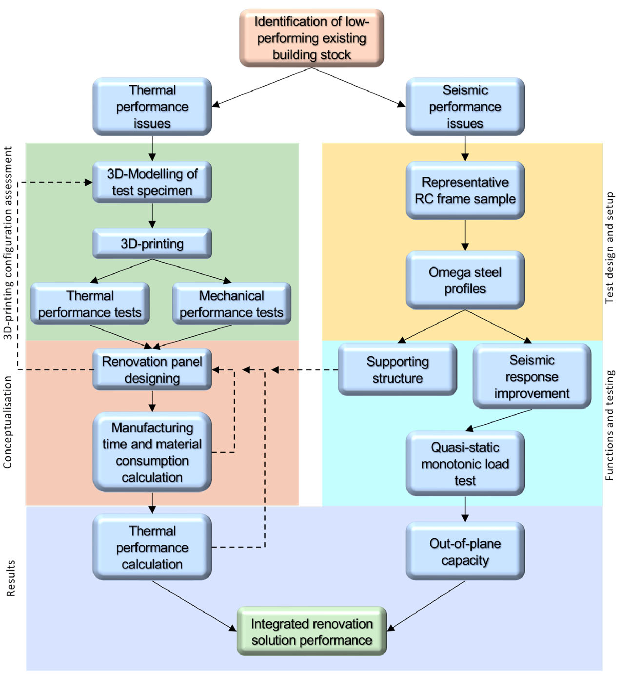
3. Conceptualisation and Development

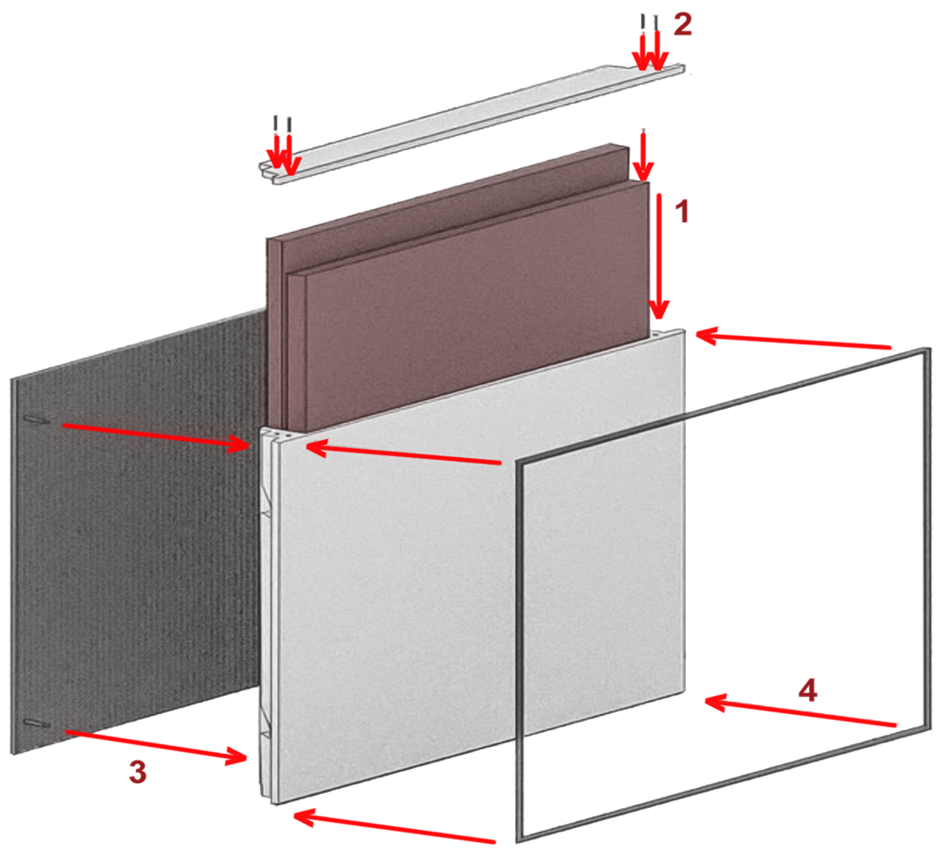
3.1. Renovation Solution and Objectives

The proposed building façade renovation solution consists of a prefabricated system of 3D-printed plastic panels fixed to the building envelope by an external steel structure. This solution was designed to respond simultaneously to the thermal, seismic, and circularity requirements of the construction sector and the current concerns of the building stock.
An external steel structure implemented in the renovated building assures seismic performance enhancement by providing additional resistance to the building structure, which is often inadequate for current standards. In addition to the structural strengthening, the external structural grid supports the polymer 3D-printed panels, avoiding the requirement for further fixation systems in the renovated building’s façade. The 3D-printed panels applied to the pre-existing façade wall provide additional thermal resistance, improving the building’s thermal performance by decreasing the building’s energy needs, which are usually high due to the poor thermal performance of the original envelope. Based on a typical wall construction composition, the panels are designed to meet the legal thermal requirements for the Portuguese context.
The developed solution is compatible with the principles of the circular economy, as it promotes the minimisation of the use of resources and the generation of waste and allows the easy disassembly and reuse of building components at the end of their life. Therefore, the following section presents the conceptualisation of the renovation solution divided into two main components: the structural grid and the renovation panel.
Figure 1 shows a flowchart on the building renovation solution development, focusing on both thermal and seismic performance improvements on underperforming building stock.

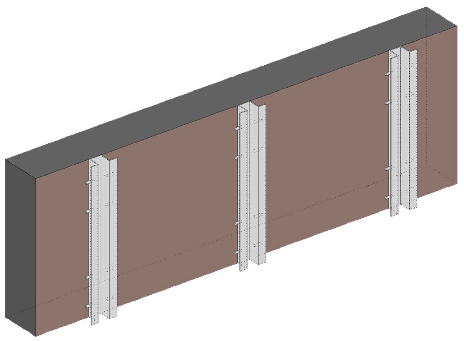
3.2. Steel Structure

The external steel structure has two roles: to improve the building’s seismic performance and to provide structural support for the renovation panels. The first aspect is fundamental, given the inadequacy of many existing buildings to the current Portuguese regulation regarding seismic requirements [37]. Moreover, the supporting function of the 3D-printed panels allows for integration between structural and energy aspects. Steel was chosen as the material used for this structural grid due to the combined need for good mechanical performance and the limited space for external applications. The steel profiles are vertically oriented and directly connected to the reinforced concrete elements, namely the beams. At the same time, there are no devices to link the strengthening system to the infill masonry wall. In this way, it is possible to reduce the time required for installation and avoid potential uncertainties due to the anchorage to the masonry.
The steel structure comprises steel omega profiles, as seen in Figure 2. These profiles should be spaced according to the renovated building seismic resistance requirements. The connection with the renovation panel will be performed by welding 14 mm diameter steel tubes to accommodate the designed connection. These tubes are 30 mm long and should be created according to the renovation panel sizes to ensure optimal fixation. The welding procedure can be industrialised to reduce manufacturing costs.
The developed solution offers an innovative approach to address seismic challenges in building renovation. The use of omega profiles and an automatised welding procedure demonstrates the modular aspect of the proposed renovation solution.

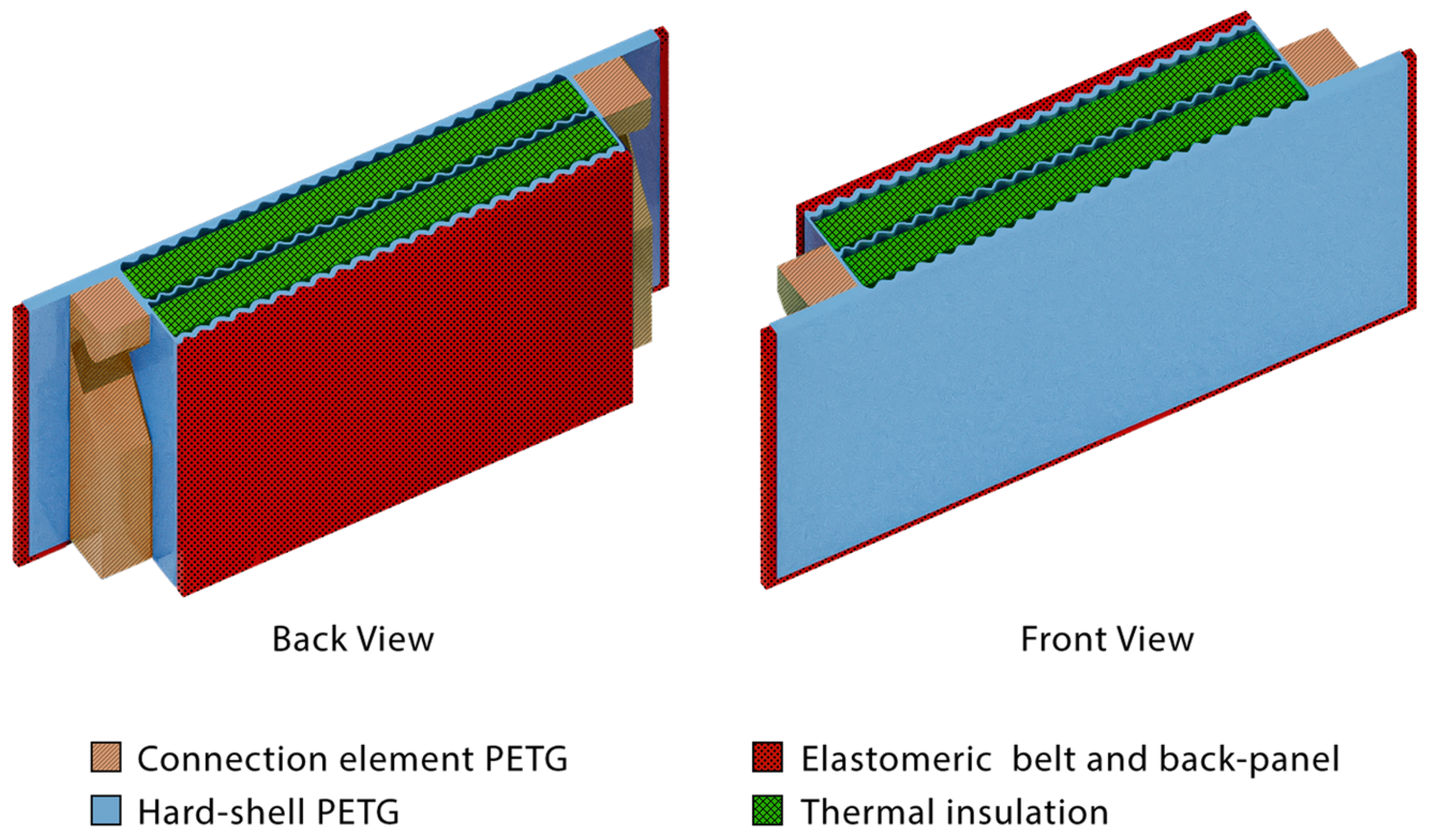
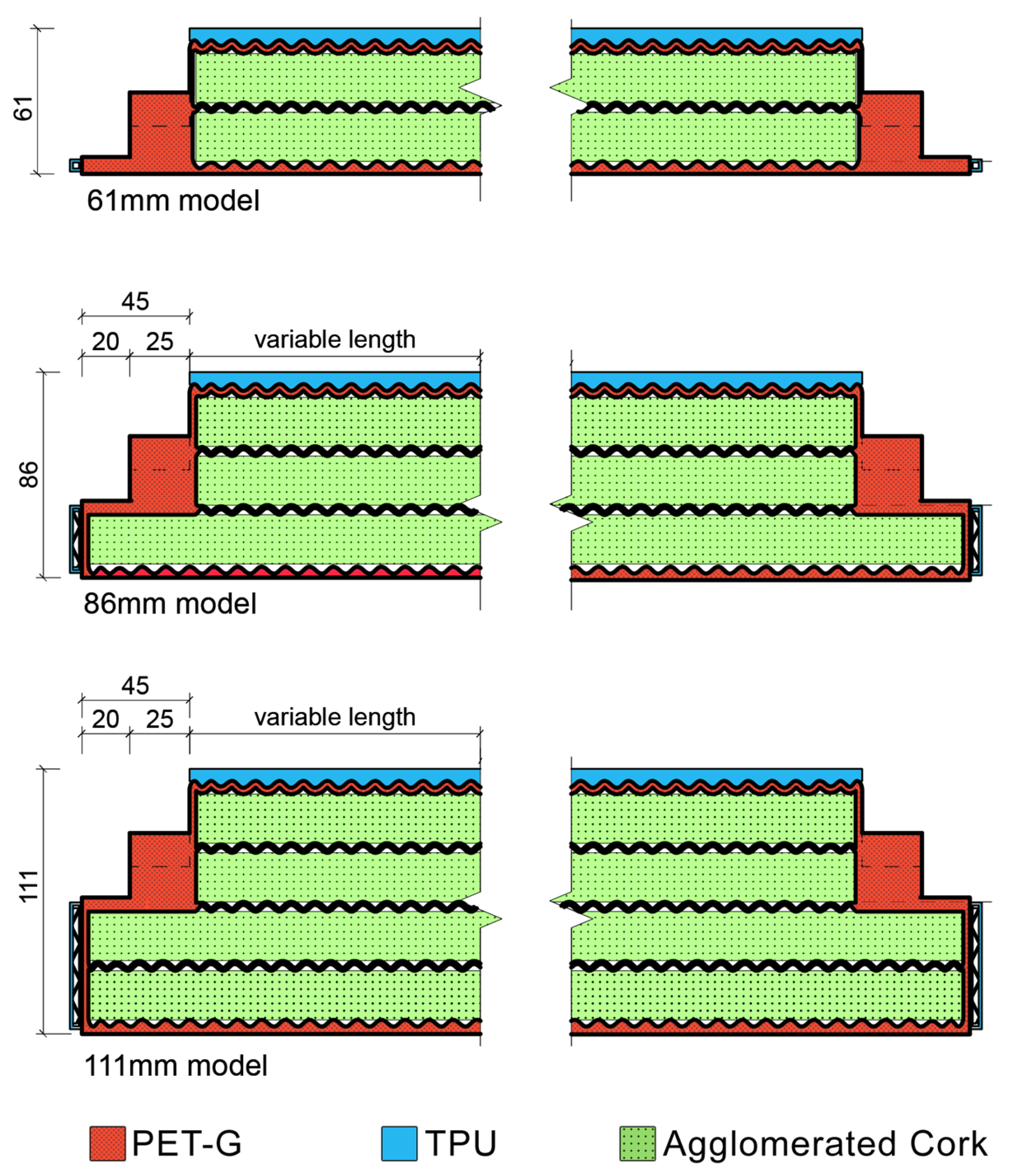
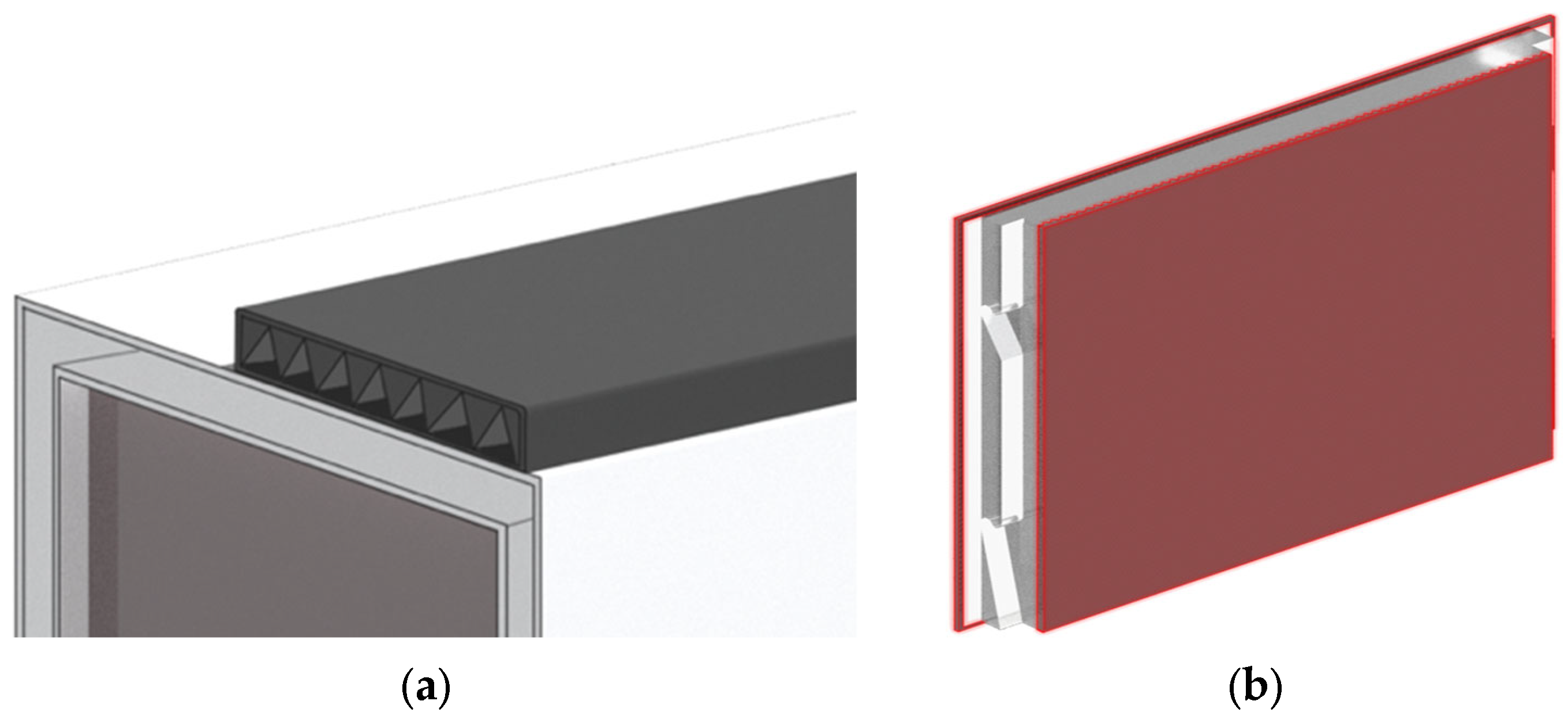
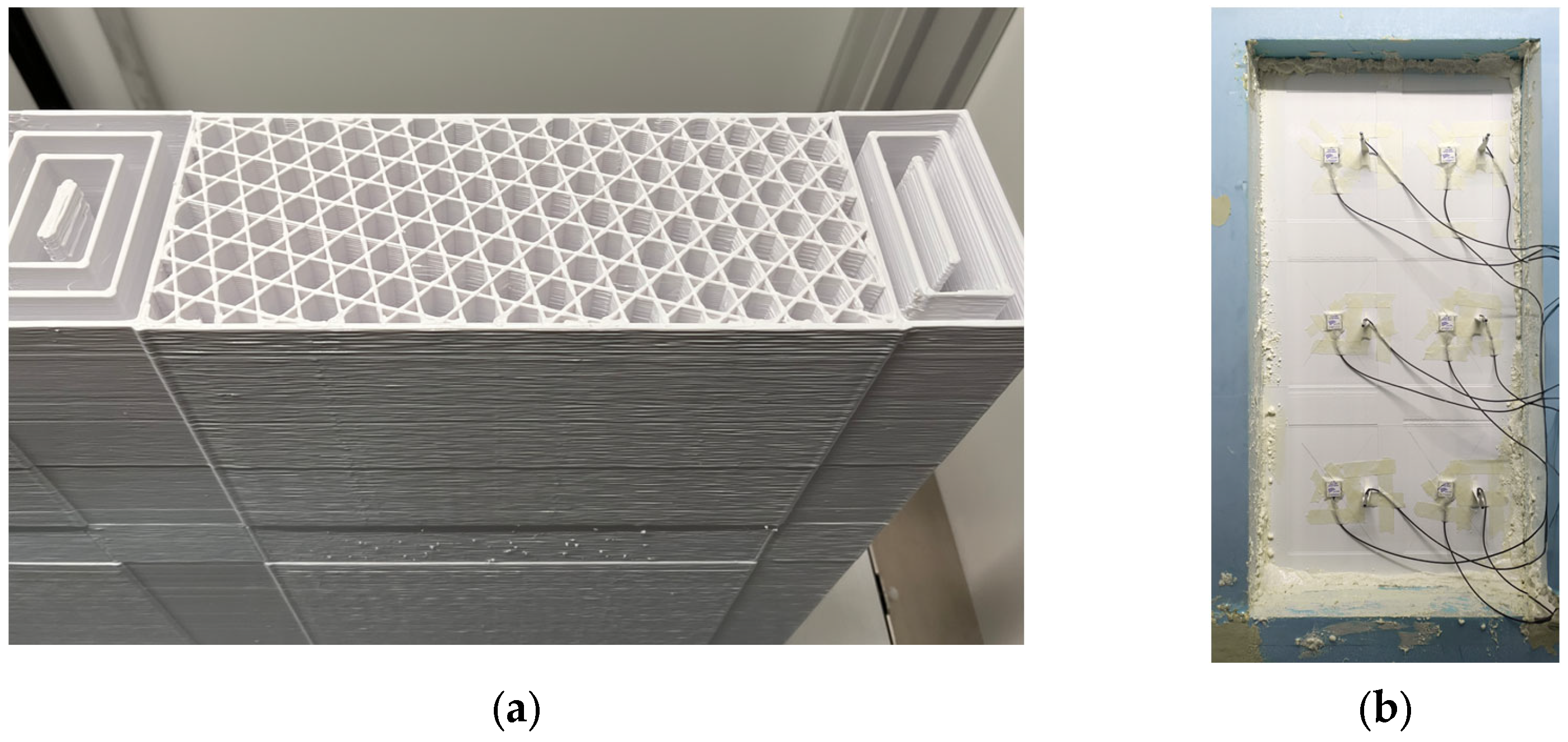
3.3. Renovation Panel

The main purpose of the renovation panel is to enhance the building’s thermal resistance. These modules cover the building’s opaque envelope, like other solutions commonly used in the renovation market, such as the external thermal insulation composite system (ETICS) [38] or other solutions like the ones discussed by Pihelo et al. [39], Sousa et al. [40], and Almeida et al. [41].
The renovation panel can be divided into four main parts to better understand the solution conceptualisation: connection element, hard shell, elastomeric band, and thermal insulation. The first is the element that serves as a connection with the structural steel structure and must allow the panel to be easily fixed to the building’s façade while also preventing theft. The second is the hard shell, which holds the insulation materials while protecting the façade from environmental agents. The third is the elastomeric belt, which is manufactured with flexible thermoplastics that accommodate imperfections in the building’s façade and thermal expansion of the material. The fourth is the thermal insulation material that improves the solution’s thermal performance, helping it to achieve the thermal legal requirements in Portugal. A scheme of the panel parts is shown in Figure 3.

3.3.1. Materials

Three materials were used to design the renovation panel solution. The primary material is thermoplastic polyethene terephthalate glycol (PET-G), which corresponds to 69% to 73% of the mass of the panel. This material was selected due to its biocompatibility, UV resistance, mechanical performance, and market availability [42,43]. PET-G is also used as a building façade material in some studies regarding 3D-printed building façade solutions [44,45]. Since PET-G is non-toxic, bio-compatible, UV-resistant, and food-safe, it is used in healthcare and food industries [46,47]. Meanwhile, thermoplastic polyurethane (TPU), representing 7% to 8% of the panel’s total weight, was used as a flexible material to be used on the surfaces connecting the panel to the pre-existing façade and in the connection between panels. This material was chosen due to its elastomeric behaviour, thermal performance, compatibility with the project’s 3D printer, and market availability [48,49,50]. TPU is also known for its many uses in the industry, including clothing, inflatable structures, conveyor belts, foams, and adhesives [51]. In addition to the thermoplastic materials, agglomerated corkboard was also used as an insulation material inside the renovation panel. This material was selected due to its high thermal resistance, availability in the Portuguese construction market, and low embodied carbon emissions [52,53].
The polymer composite performance for such use in building façade renovation solutions must comply with the same requirements as any façade material. These can be abridged to a polymer façade material with UV resistance, temperature and humidity resistance, fire performance, non-toxic gas emitting when exposed to fire, good chemical resistance, wind resistance, and sufficient mechanical performance to withstand strong winds.
Regarding building temperature, it should adequately resist humidity and environmental changes while withstanding extreme temperature variations between −16 °C and 47.3 °C, the minimum and maximum temperatures recorded in Portugal [54]. The selected polymers have a glass transition temperature of approximately 80 °C [55,56] for the rigid PET-G, a melting point of 192 °C and a glass transition temperature of −21.8 °C for the elastomer TPU [57]. Both are within the acceptable range of the temperature performance requirements.
Based on the typical climate in Portugal, the selected raw materials must withstand at least an average annual UV radiation of 1646 kWh/m2 and maximum monthly radiations of 241 kWh/m2. The selected materials are resistant, with TPU showing discolouration with minimal mechanical performance degradation to UV light. There is, however, the need to test the UV radiation degradation of the materials further for the expected lifecycle exposure of 30 years.
A concern in developing any renovation solution made from plastic is its fire performance. As thermoplastics can be combustible, using the wrong material on the building façade can lead to the rapid spread of fire throughout the building [58,59]. To address such issues, polymer composites used on a building façade must be self-extinguishable to prevent the fire from spreading horizontally [60]. Furthermore, the two-panel materials should abide by the fire-resistance building element regulation. As defined in NP EN 13501-1 [61], the panel fire-resistance classification should be between B and S2, allowing the panel to be used in larger buildings.
Achieving flammability requires using a fire-resistant polymer composite, either through the properties of the polymer or by adding a fire retardant to a selected polymer. The polymers selected in this study, PET-G and TPU, have not yet been evaluated for their fire resistance following the EN 13501-1 standard for fire classification of construction products and building elements [61]. Future developments of the proposed solution will include optimising materials, also considering this issue. Table 1 presents a summary comparison between the plastics used in the study, showing that there is still room for material improvement to meet the façade renovation panel requirements [62,63].

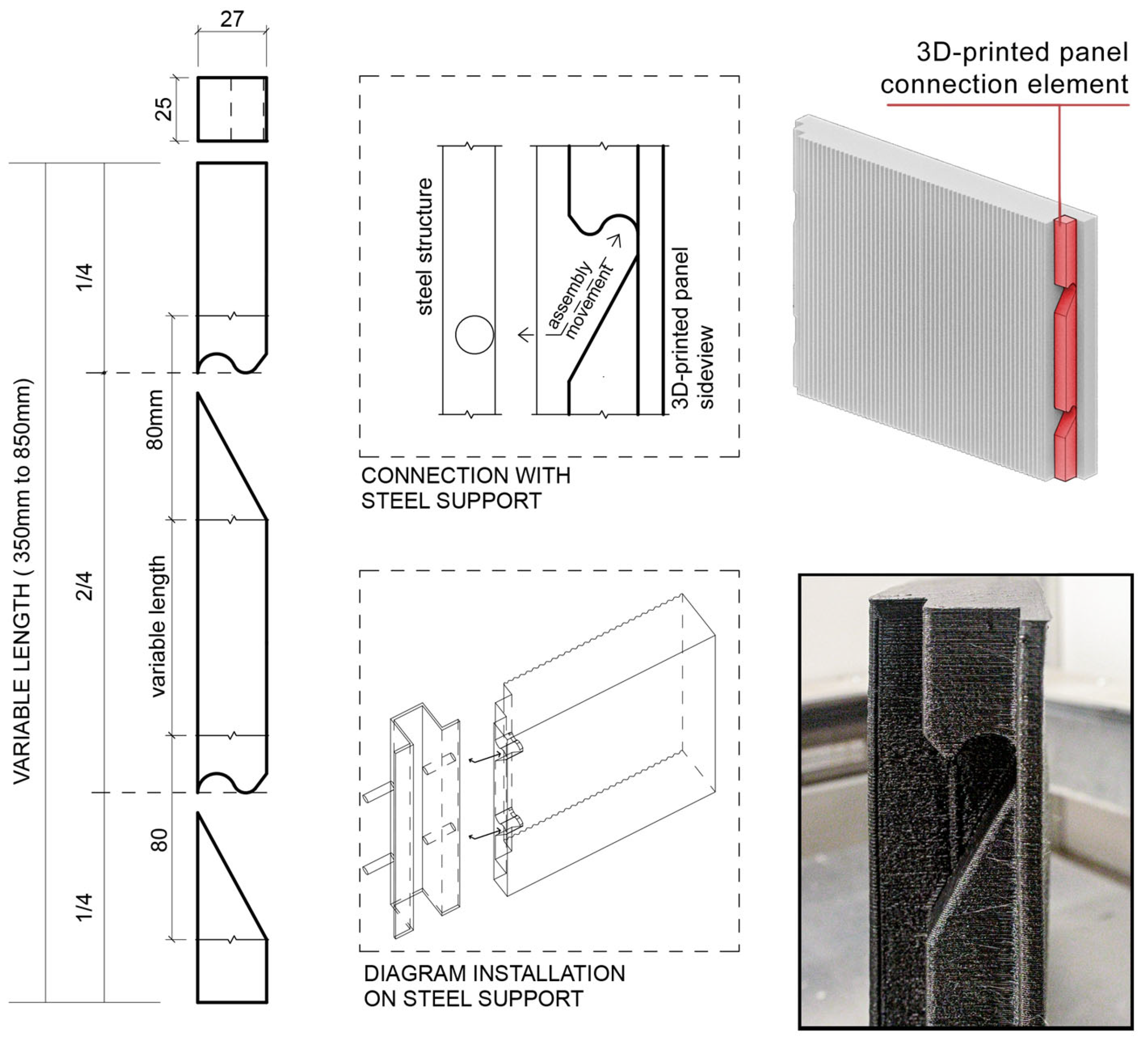
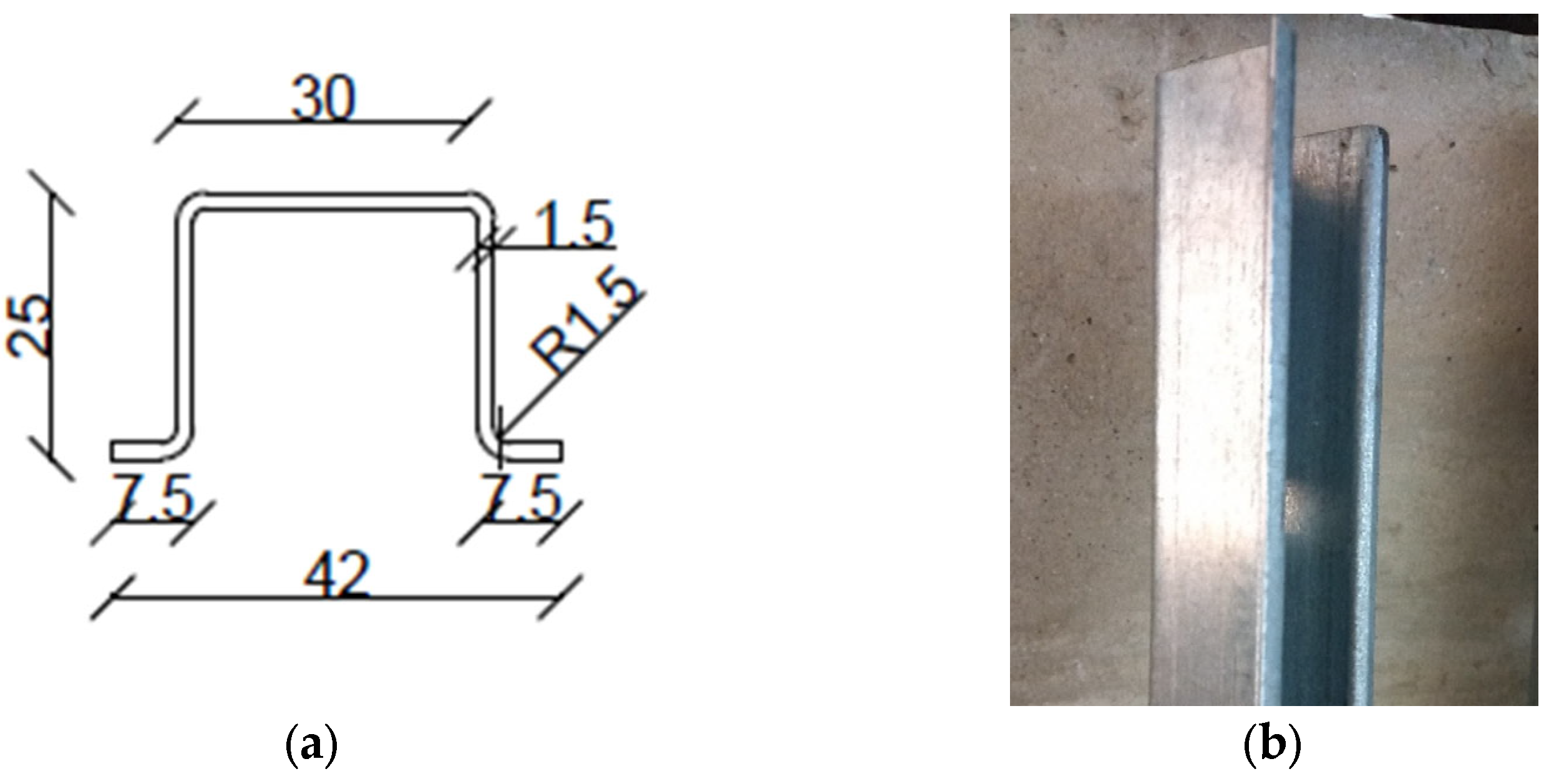
3.3.2. Connection Element

The panel integration into the steel structure is performed through a plug-in system, as seen in Figure 4, allowing quick and clean installation and disassembly at the end of the renovation solution’s life cycle [64,65]. The plug-in solution increases the advantages of a modular and prefabricated renovation solution, leading to a renovation solution with less environmental impact and waste generation [16,66,67]. It should be noted that the façade renovation solution will be in direct contact with the building’s pre-existing façade. To avoid creating significant thermal bridges due to the direct contact of two hard and sometimes irregular surfaces, the renovation panel has a flexible back zone made of an elastomeric plastic that aims to accommodate the imperfections of the pre-existing façade and guarantee a suitable connection between the renovation panel and the pre-existing façade [68].
The conceived plug-in system blocks the removal of the panel when another panel is placed above. Thus, in a building renovation, the lower panels will be locked until the upper panels are removed, thus preventing any passer-by from removing a panel from the building. This connection element will be 3D printed with the same characteristics as the hard-shell element, described in the following section, to guarantee maximum structural connection between the parts. These two elements’ characteristics resulted from the optimisation carried out in a previous study [18] concerning the infill geometry, weight, and thermal and mechanical performances. Printing was conducted with a 1.2 mm nozzle with a layer height of 0.6 mm with two perimetral layers and four top and bottom layers. The printed object was filled with a 25% stars infill configuration, which was the optimal infill configuration for this specific study, as shown in Figure 5, with mechanical resistance ranging from 15 kN to 20 kN in flexure. The printing configuration is the one shown in Table 2.

3.3.3. Hard Shell

The panel’s hard shell serves as a rigid envelope for the insulation materials, and it has three model variations, 61 mm, 86 mm, and 111 mm, which are related to the panel’s thickness and internal composition. The first model designed was the 86 mm one, followed by a thicker and thinner version. Therefore, the decision to make three different variations made it possible to test different thermal renovation solutions, allowing the adjustment of the consumption of material used in the production of the panel to the thermal performance requirements of the renovated building. These different models must have solutions to accommodate different numbers of insulating panels, thus adapting to the needs of the building to be renovated. The number of spaces for placing thermal insulation materials varies, as shown in Figure 6.
A noticeable aspect of the hard shell is the wavy pattern of its internal walls. This pattern improves the resistance to deformities in the manufactured piece that are expected on a high single-layer perimeter print. The wavy wall perimeter was designed in a double perimeter to decrease material consumption and printing time, as seen in Figure 7. This shell element takes advantage of the additive manufacturing process by being flexible in dimensions to fit the intervals of the structural grid. This flexible dimension, however, is limited by a minimum and maximum value according to printer dimensions and the minimum dimensions of the connection’s elements. The criteria used to define these features were the panel total weight, 3D-printer maximum dimensions, and connection element dimensions.
The panel minimum size, 230 mm by 110 mm, is defined as connection element dimensions, as discussed previously. The maximum size of the module is 1100 mm by 800 mm for linear modules and 500 mm by 500 mm by 800 mm for corner modules, limited by the printer’s maximum printing dimension of 1100 mm by 500 mm by 840 mm. The square meter of the PET-G module of this size weighs 12.3 kg to 18.2 kg, varying from the thinnest to the thickest model. Therefore, the size of the panel also impacts its workability. Using lighter panels avoids using heavy machinery to move panels around a construction site [69], making the solution more sustainable. Table 3 shows the weight and printing time of panels with different thicknesses.

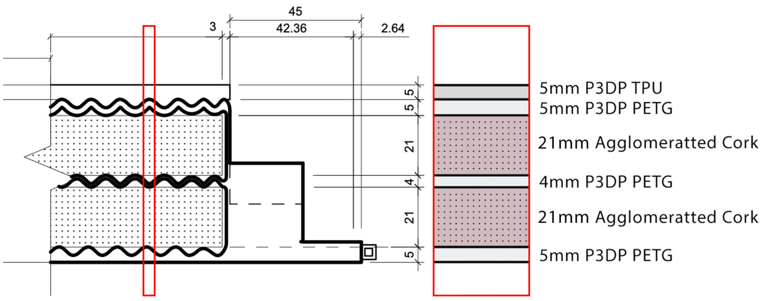
3.3.4. Elastomeric Belt and Panel

Thermoplastic materials, such as PET-G, have a high thermal expansion rate. Consequently, a thermoplastic panelised building façade renovation must accommodate the material expansions and contractions of the polymer. Hence, a belt of an elastomer polymer, TPU, is designed to contour the panel modules serving as an expansion joint.
The renovation solution must also avoid water infiltration through panel joints to avoid possible moisture-related pathologies in the building façade. The water tightness of a panel renovation solution is a commonly discussed aspect due to moisture and water infiltration risk [70,71]. Therefore, a 5 mm thick TPU belt outlines the panel module to create a water-tight seal. The elastomer belt is hollow with a 3D-modelled internal triangular structure, as depicted in Figure 8a. The panel connection water seal will be ensured through the pressure between the compressed elastomeric belts [72,73]. The elastomeric thermoplastic parts of the panel are highlighted in Figure 8b.
Another crucial part of the panel’s elastomeric zones is the TPU back panel, as already referred to. This 5 mm thick back panel, printed without infill and with two perimeter layers, accommodates the imperfections of the pre-existing building façade, being able to deform accordingly when applied to the building. This part is attached to the back of the PET-G module using insertion pins that will be printed on both parts of the module. The manufacturing of the TPU parts uses the same configuration as the PET-G module, with only some changes regarding the 3D-printing configuration, as shown in Table 4. Depending on the model, TPU material consumption does not vary as much as PET-G, because the part that consumes the most material is the back panel, which is similar across all panel modules. It is worth noting that the quantity of TPU material in a unit area renovation solution may change depending on the characteristics of the panel modules.
By large, the 3D printing of the TPU parts represents a small percentage of the total panel module renovation solution, but it plays an important role in the renovation solution. The rubber-like characteristics of the material are essential to the building renovation façade by creating a pressure water-seal while accommodating building façade imperfections.

3.3.5. Thermal Insulation

Adding agglomerated corkboard as an insulation material ensures the panel’s thermal performance. Depending on the model, it uses 20 mm thick agglomerated cork boards to fill the hard-shell spaces, varying from two to four per panel module. The thermal insulation represents 19% to 24% of the renovation solution mass, which is significant when considering the amount of material consumed for building façade renovation. The thermal insulation is also protected from UV radiation and water infiltration by the PET-G hard shell. Therefore, the insulation requirements must be compatible with the hard-shell material and accomplish the goal of improving the target building façade’s thermal performance following the Portuguese law requirements [74].
In addition, the division of the insulation element into 20 mm layers defined in the hard-shell element allows future customisation of the interior composition. Therefore, different material combinations can be used to optimise the thermal insulation and CO2 emission for each specific building requirement and location.

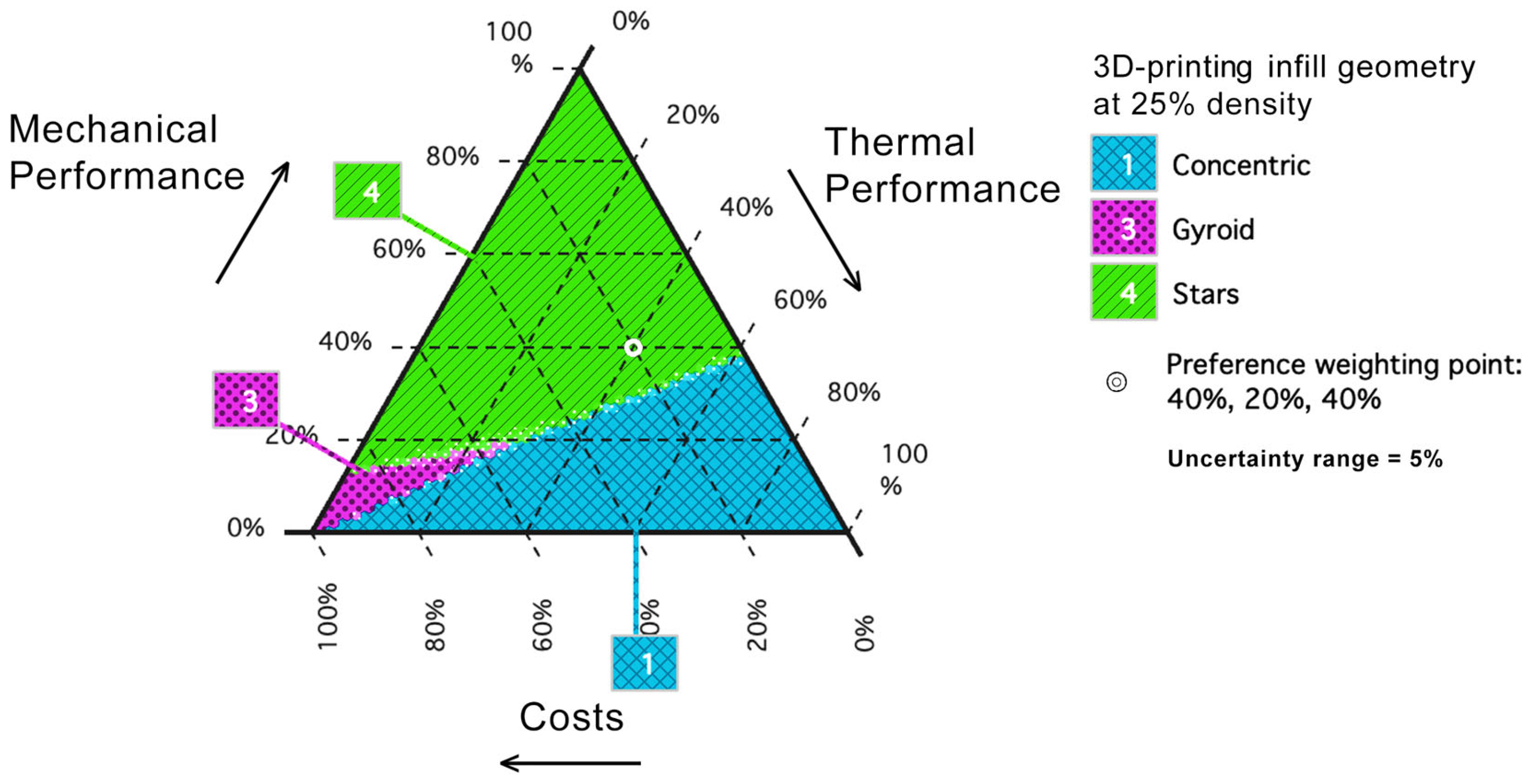
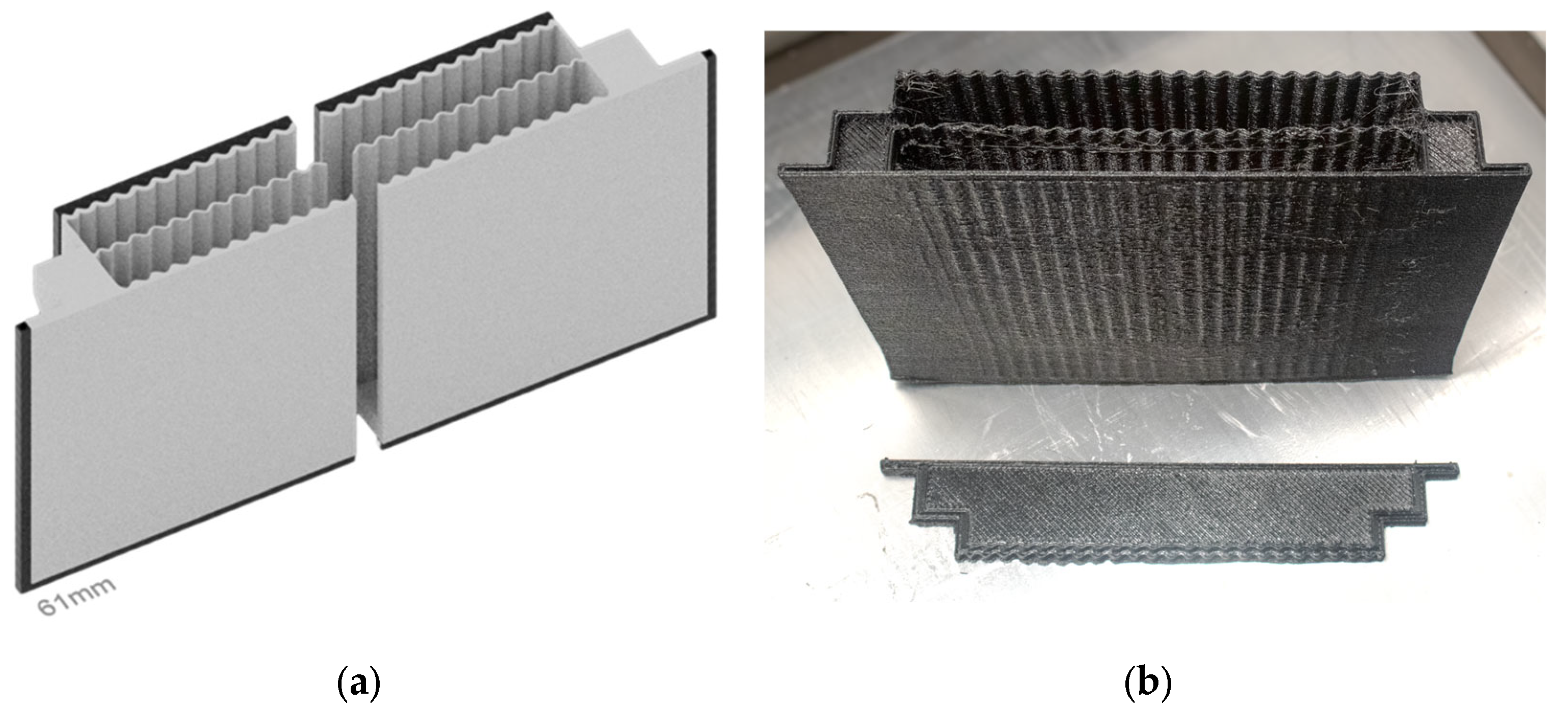
3.3.6. Panel Manufacturing

The sustainability of the renovation solution was a major concern during the development of the building renovation solution. Hence, its assembly and manufacturing process was conceptualised to allow the use of recycled materials and the easy disassembling and recycling of the solution at the end of its lifecycle, ensuring that the solution would fit a circular economy.
FDM 3D printing allows using recycled materials [75,76]. Therefore, the panel modules could be manufactured with recycled polymers that also fit UV resistance and biocompatibility requirements. Additionally, the insulation material used in this development could be replaced by a recycled material as long as it is compatible with the polymer. These actions could result in a recycled renovation solution.
The modular approach of the renovation solution aims to assemble without using adhesive materials to avoid contamination of the materials used and, at the same time, assist in the process of separating materials to be recycled at the end of life [77]. The manufacturing process was divided between 3D printing of PET-G and TPU parts to avoid unnecessary waste and material contamination. The separation of manufacturing also avoids waste generated from material discarded when changing filaments.
The panel modules should be assembled in a step-by-step process, easy enough to be hand-made but can also be easily automated. Figure 9 illustrates the assembly of the renovation panel parts. Firstly, the insulation material should be placed inside the PET-G hard shell, and the lid should be closed and secured with nylon screws, holding the panel closed with the insulation material inside. Secondly, the TPU back panel must be fixed by the matching pins printed with the model. Finally, the TPU belt can be stretched into place, hence being easily assembled and disassembled.
The renovation solution on-site assembly is designed to be equally simple. The structural grid should be fixated to the renovated façade as specified in the previous topic—Section 3.3.2. Then, the renovation panel can be plugged in place following the fixation support pins, from bottom to top, ensuring the proper connection between the panel and the structural grid. This ensures that the panels are secured in place and cannot be removed by anyone without removing the upper module.
Generally, the renovation solution is designed to be simple and modular, avoiding unnecessary waste while being designed for recycling. The easy on-site assembly of the renovation solution should be performed without using adhesive materials to avoid waste generation and allow for fast construction, reducing costs and emissions.
It should be noted that this study has not yet calculated the costs associated with this panel’s production, as it is still in the laboratory phase of prototype production. Additional studies are still needed to optimise the panel’s characteristics to have it ready to be launched on the market. Furthermore, it would be necessary to move from the laboratory production phase to the industrial production phase, which would reduce the costs associated with its production resulting from the industrialisation of the process. Additional studies to evaluate the cost-effectiveness of the proposed solution and possible environmental impacts are still necessary. Developing a business model for introducing this product to the market is still being prepared.

3.4. 3D-Printing Energy Consumption

The energy consumed during the 3D-printing process, specifically the FDM or FFF process, is another factor to consider when assessing the sustainability of a building renovation solution primarily 3D printed.
Although FDM 3D printers, as an additive manufacturing process, are quite straightforward in terms of energy demand, their energy consumption quantification can be complicated due to a vast number of factors that can directly impact the manufacturing energy consumption [78,79,80]. Any small changes in the 3D-printing configurations impact the overall manufacturing energy consumption [81] by increasing manufacturing time or compromising the desired characteristics of the printed object. This could mean that further optimisation and research on the renovation panel’s development could reduce manufacturing energy consumption.
The large-scale 3D printer used to prototype the panel modules had its energy consumption values measured during the prototyping manufacturing of the renovation panel. The measurement was performed through an energy measurement consumption from the model LEXMAN 84,586,358 connected to the power outlet of the Builder Extreme Pro 1500 industrial 3D printer. The results measured the following energy consumption: idle state (67.30 W), calibration state (116.99 W), warm-up state (1977.98 W), and build state (193.03 W). Therefore, a square metre of the plastic renovation solution accounted for the PET-G and TPU materials, considered 5 min of calibration state, 10 min of warm-up state, 118 to 202 h of build state for PET-G, and 50 to 63 h of built state for TPU, resulting in a total power demand ranging from 33 kWh/m2 to 52 kWh/m2 depending on the panel thickness. These results, however, can be different in different settings and printing configurations, with differences in energy consumption and printing time.
Regardless of the overall energy consumption of the 3D-printing process, it is worth mentioning that this manufacturing process only consumes electricity, which can be generated from renewable sources, and the materials consumed, which can be recycled and recyclable [82]. This can lead to a zero-emission circular manufacturing process.

3.5. Development Limitations

The development of the proposed building renovation solution observed some limitations due to several factors that shaped the results presented. The availability of 3D-printing materials and technology was a vital limitation factor. As discussed in previous sections, other thermoplastic materials could be used as primary materials for the renovation panel if these materials were available. The printer size and configuration limitations were also determinants in the design of the renovation panel.

4. Renovation Solution Performance

The thermal and seismic performance of the renovation solution is a determining factor in the quality and viability of the proposed solution. The integration of both performances marks the novelty of the developed solution. Therefore, the following sections will discuss the proposed renovation solution’s thermal and seismic performance enhancement following the Portuguese legislation requirements.

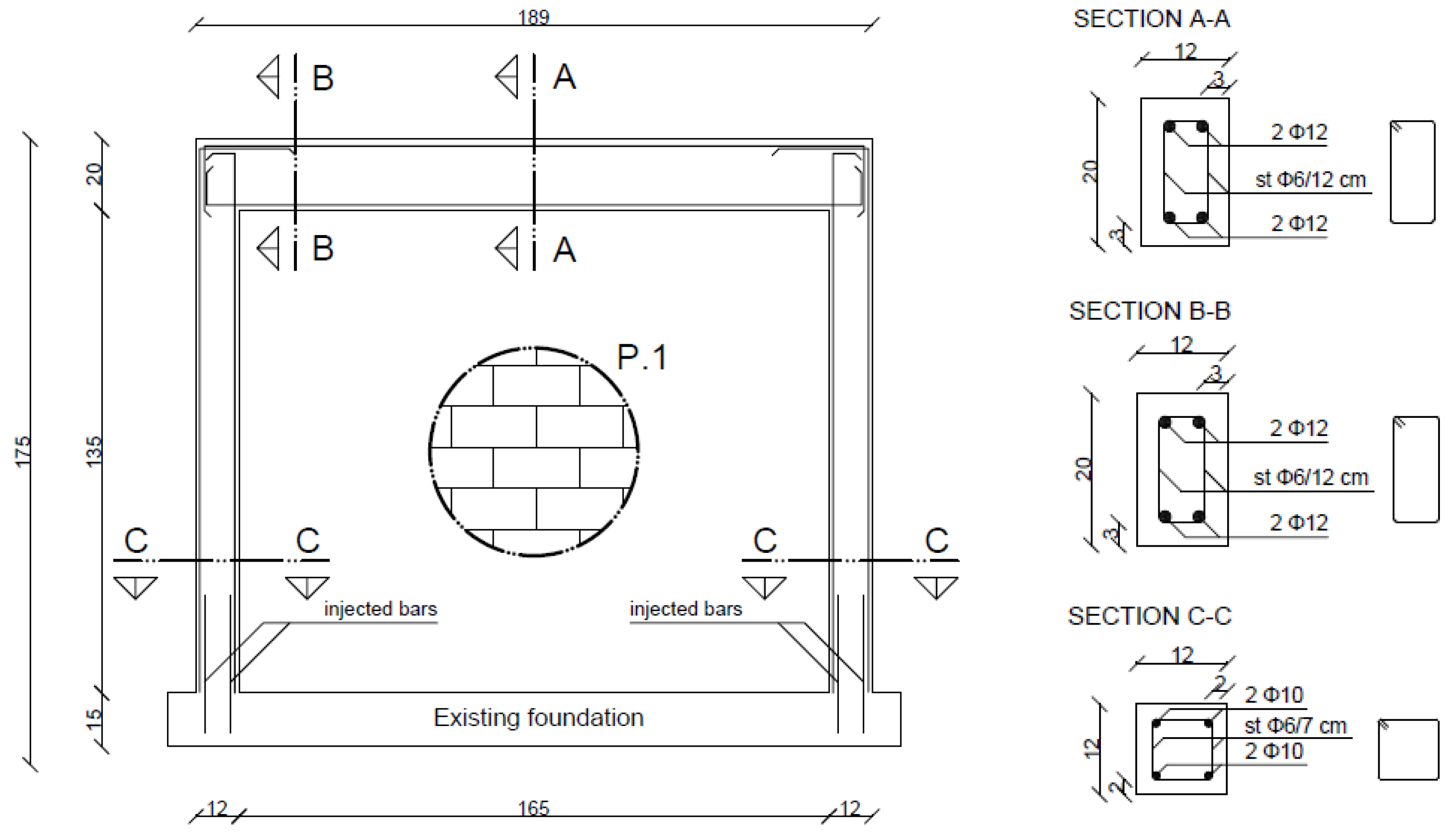
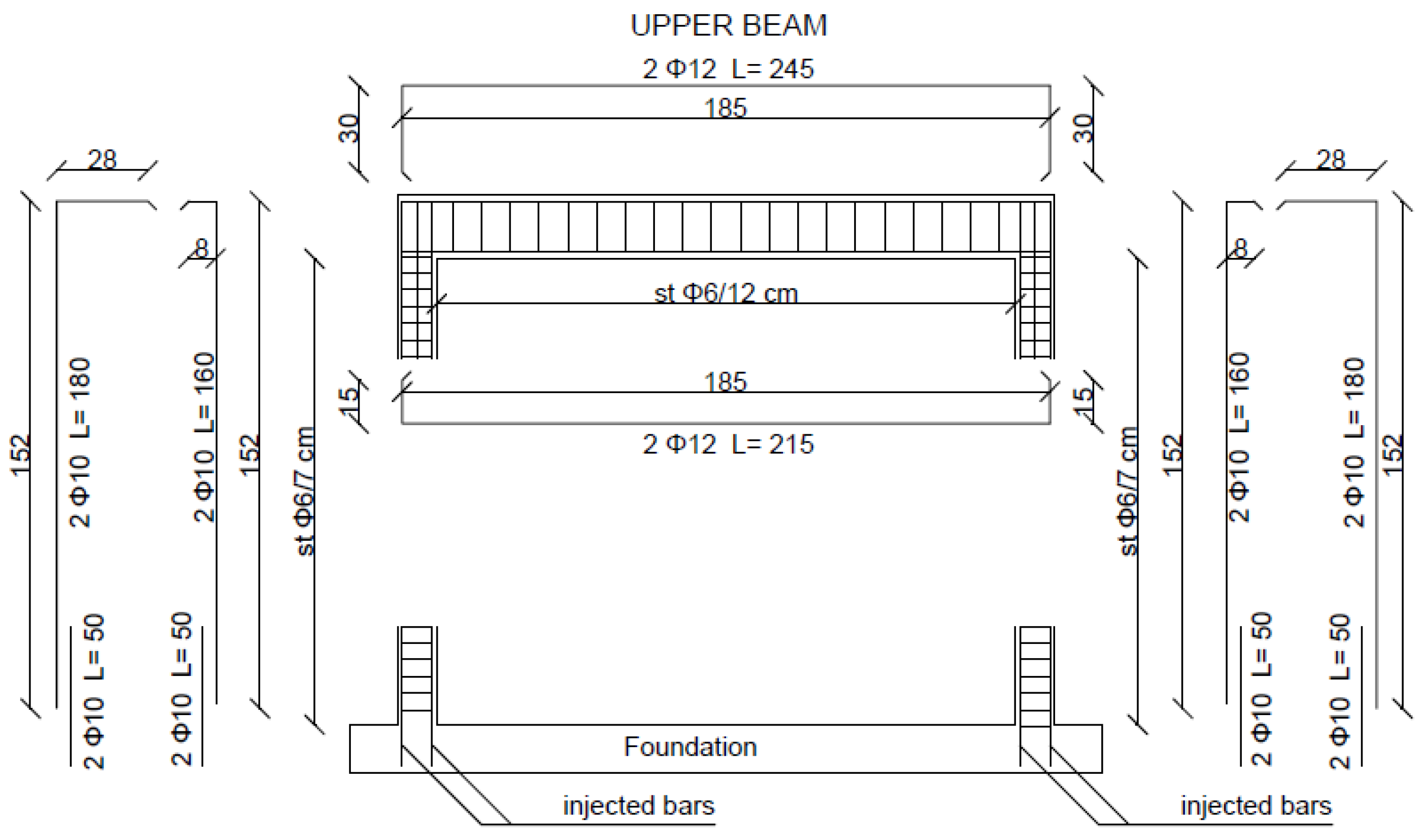
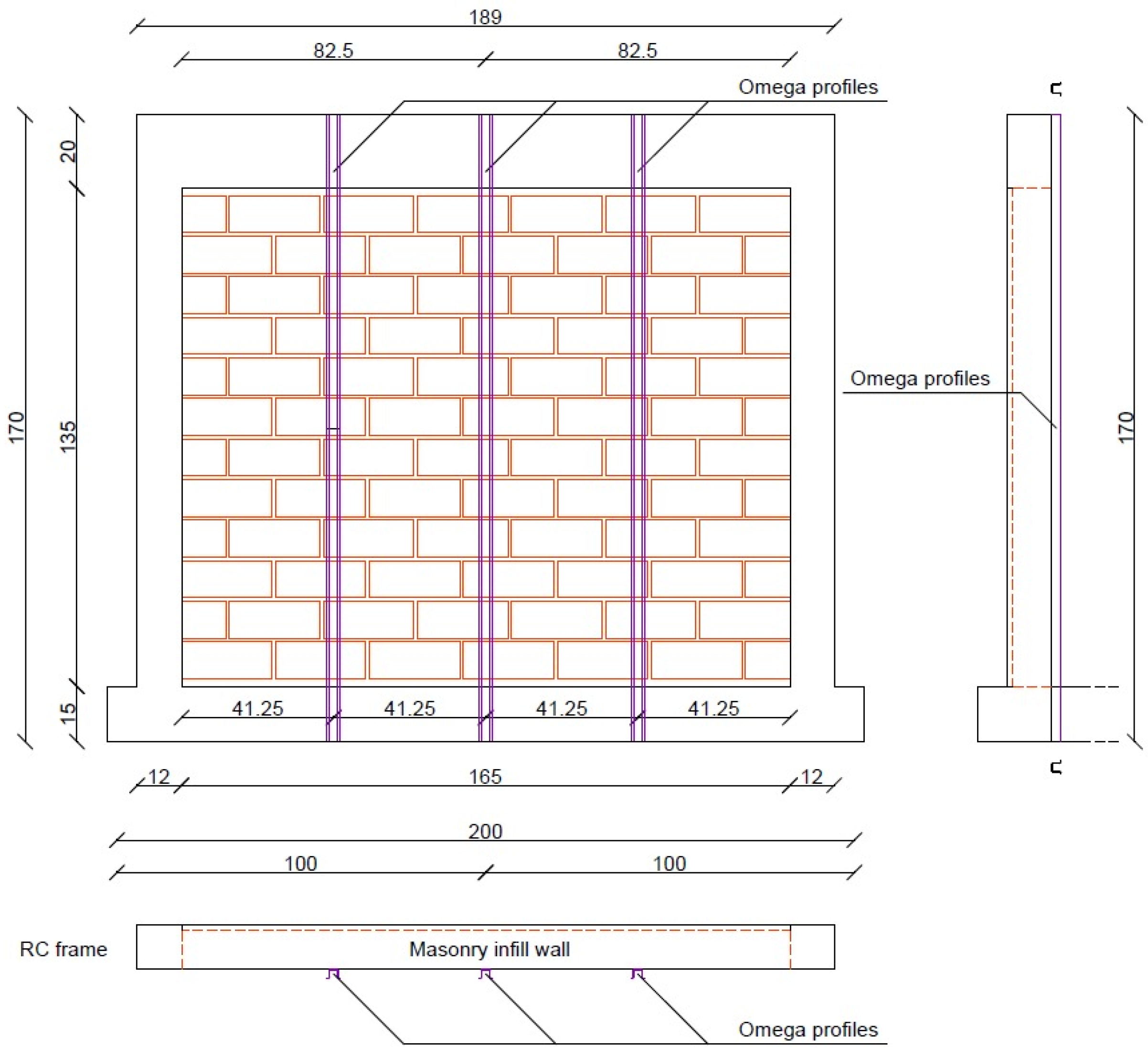
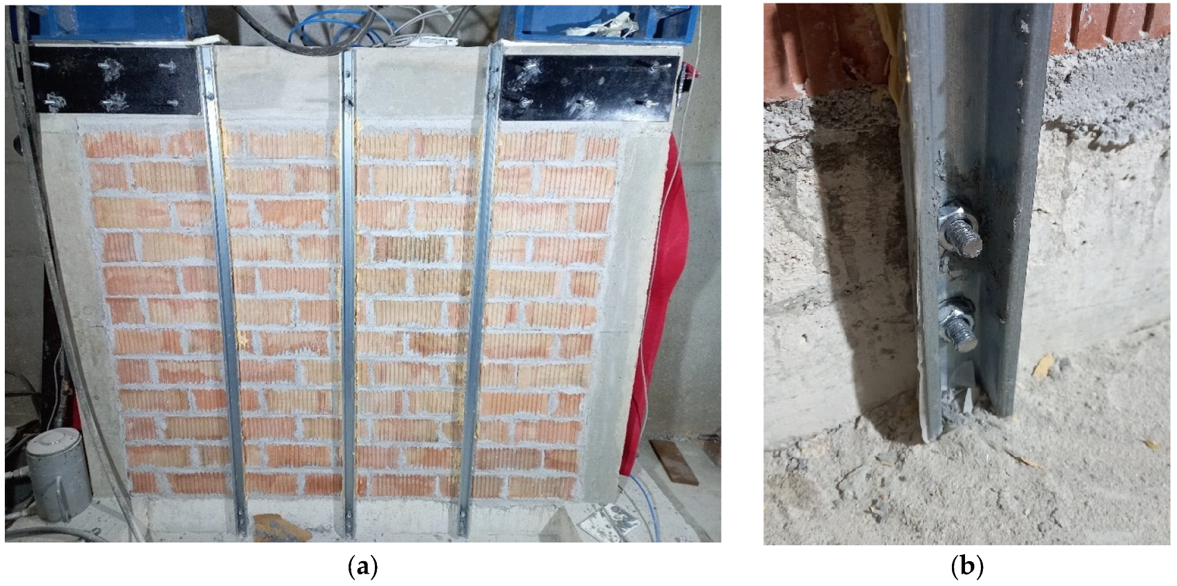
4.1. Seismic Renovation Structure

The structural function of the solution (i.e., increasing the building’s seismic capacity and supporting the panels) is fulfilled by using vertical steel profiles. In detail, the strategy employs cold-formed profiles with omega shapes connected to the frame’s reinforced concrete (RC) elements through injected anchorages. The advantages of such a solution are its versatility for different pre-existing conditions of the buildings (e.g., the presence of openings, complex geometry) and the system’s adaptability according to the value of the seismic demand. Indeed, it is possible to change either the section’s characteristics (i.e., geometry and thickness) or the horizontal spacing between the vertical elements. This way, the section size can be optimised based on the specific requirements.
While the out-of-plane capacity of the masonry infill wall alone can be computed following the recommendations of the Eurocode 8 [83], the evaluation of the contribution provided by the strengthening elements takes into account several factors, such as (i) uncertainties in the material properties; (ii) possible premature collapse of the infill wall due to masonry cracking; (iii) combined structural response of the infill wall with the still grid reinforcement. Due to this, it was necessary to test the infill wall with and without the strengthening system to experimentally assess its possible benefits in terms of out-of-plane behaviour.

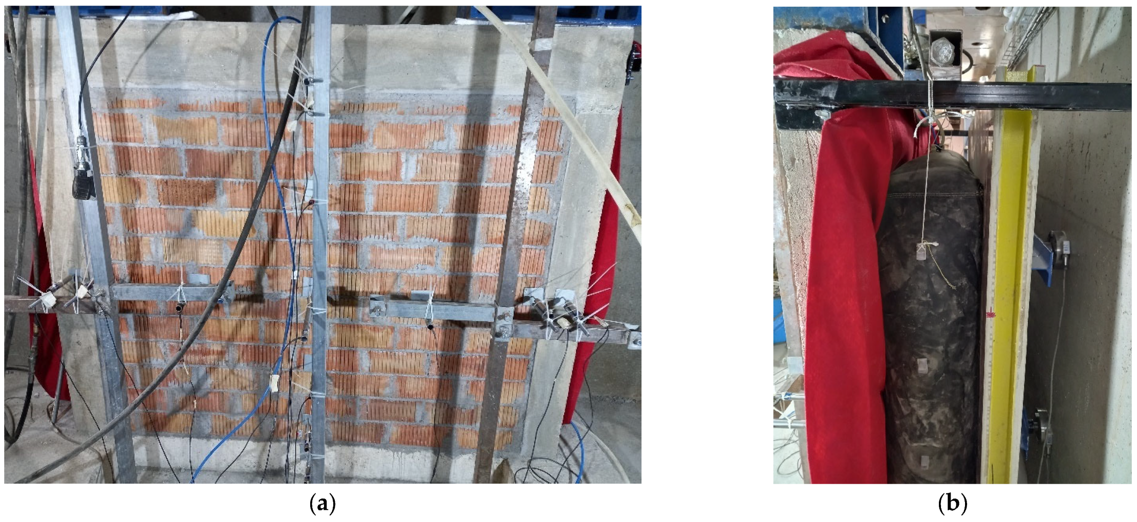
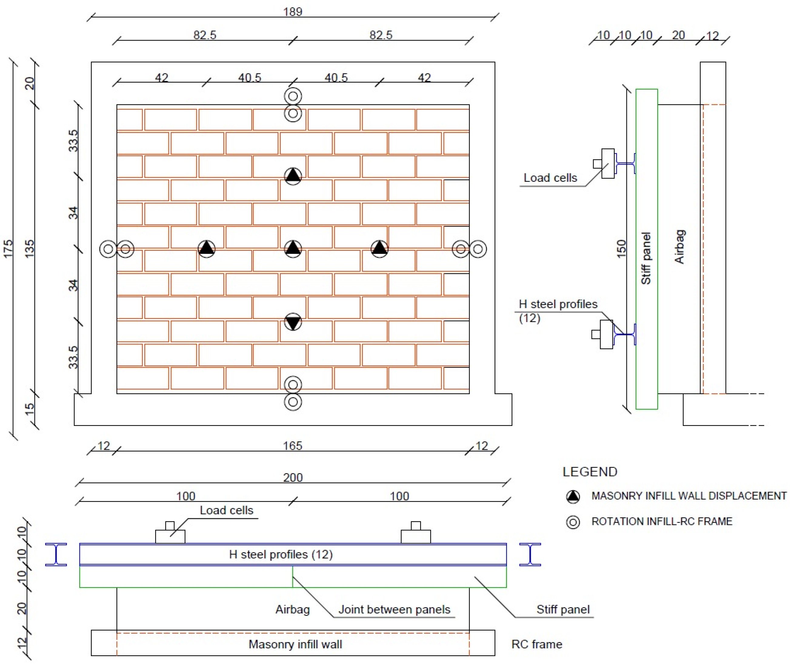
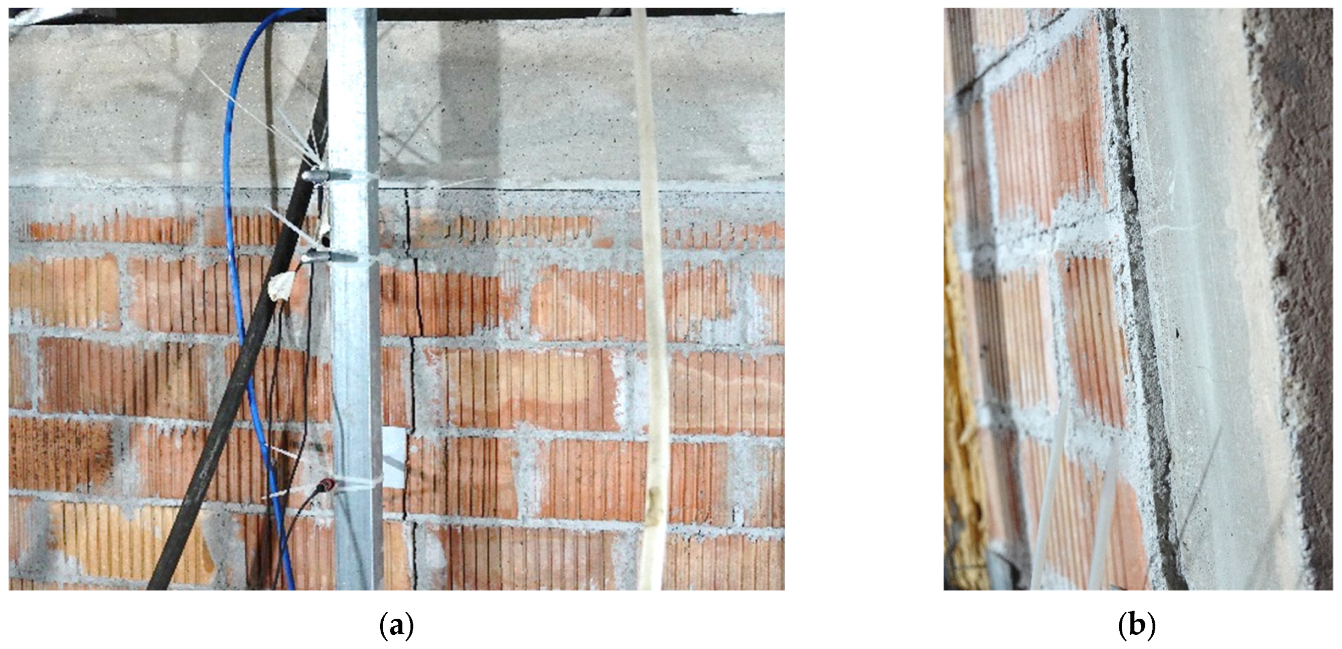
4.1.1. Experimental Setup

Two experimental tests were carried out on a half-scale RC frame with and without the strengthening system to assess the structural performance enhancement provided by the designed solution. The RC frame and infill wall characteristics considered for the specimen have been based on the full-scale sample studied by Furtado et al. [84], whose dimensions are representative of those presented in the Portuguese building stock. For practical reasons, half-scale dimensions of the specimen were considered for the test. The frame geometry, the dimensions of the RC elements, and the corresponding reinforcement detailing are reported in Figure 10 and Figure 11.
Regarding the materials employed for the sample, a C20 concrete class was used for the RC elements and an M5 cement mortar for the masonry infill wall. The wall was made of clay bricks with dimensions 10 cm by 10.5 cm by 24.5 cm, which was in agreement with the half-scale of the specimen. A loading system composed of a nylon airbag with dimensions 155 cm by 130 cm and a reaction structure on the opposite side made of a rigid panel and HEB profiles was used to apply a uniformly distributed load on the infill wall. In addition, four load cells inserted in correspondence with the steel profiles allowed the measurement of the actual load applied to the wall. The total load applied by the airbag was computed by the sum of the single load values measured by the four load cells. The RC frame was fixed to the laboratory wall using fixing steel devices. Two vertical actuators were placed at the top of the columns to simulate the presence of the upper elements, as for real RC structures. The load value applied by such actuators was computed using the stress values considered in similar tests performed at the University of Minho (e.g., [85]) and taking into account the scale factor used for the sample. Specifically, a vertical load of 50 kN was applied to each column. The test setup used for the unreinforced masonry (URM) wall testing is illustrated in Figure 12.
An automatic system was used to control the pressure increase inside the airbag following a displacement control protocol, with the main point at the centre of the wall. A total of 13 linear variable displacement transducers (LVDTs) were employed to measure the displacements in characteristic points of the infill wall and the RC elements (see also Figure 13). In addition to the central point, the displacements at the quarters and the edges of the wall were measured to characterise the evolution of the displacements during the test. Moreover, the LVDTs placed on the RC elements allowed the assessment of the relative displacements between the frame and the infill wall, evaluating the possible detachment of the masonry from the RC elements. A quasi-static monotonic load increase until the achievement of the maximum capacity of the infill was considered. The main output obtained from the experiment was a force–displacement curve representing the out-of-plane response of the wall subjected to horizontal loading and the corresponding cracking pattern.
Following the test performed on the URM wall, the infill was replaced by a second wall with the same characteristics of materials and elements. This second wall was reinforced by the integrated building renovation solution to assess the possible benefits of the out-of-plane capacity increase provided by the strategy. In detail, three steel profiles with omega section and constant interspacing (i.e., equal to one-quarter of the wall length) were placed vertically to strengthen the wall. The chosen section followed the average dimensions employed for the specific renovation solution, which, however, can be adapted according to the specific conditions and loading requirements. Furthermore, the omega profiles were scaled following the dimensions of the half-scale specimen. The half-scale omega section and a view of the steel profile are reported in Figure 14, while the schematic representation of the reinforcement applied to the second infill wall is shown in Figure 15. For the sake of simplicity, the presence of the 3D-printed panels was not considered in this test (they do not perform any structural role in the solution).
A picture of the reinforced masonry infill before the test is reported in Figure 16a. The connection between the reinforcing and RC elements (top beam and foundation) was made through injected anchorages, two for each side (see Figure 16b). Instead, there were no fixing elements between the reinforcement and the infill wall, which mainly interacted by contact that was ensured using levelling mortar to avoid possible load concentration in the masonry. Similarly to the URM wall testing, 13 LVDTs were used with the same disposition for the reinforced structure to obtain an optimal assessment of the displacements in characteristic points of the wall. Due to the presence of the omega profiles in the centre and at the quarters of the wall, the corresponding LVDTs were slightly moved to directly assess the displacement of the masonry, which may be different compared to the steel elements, particularly in the first part of the loading test (i.e., elastic field).

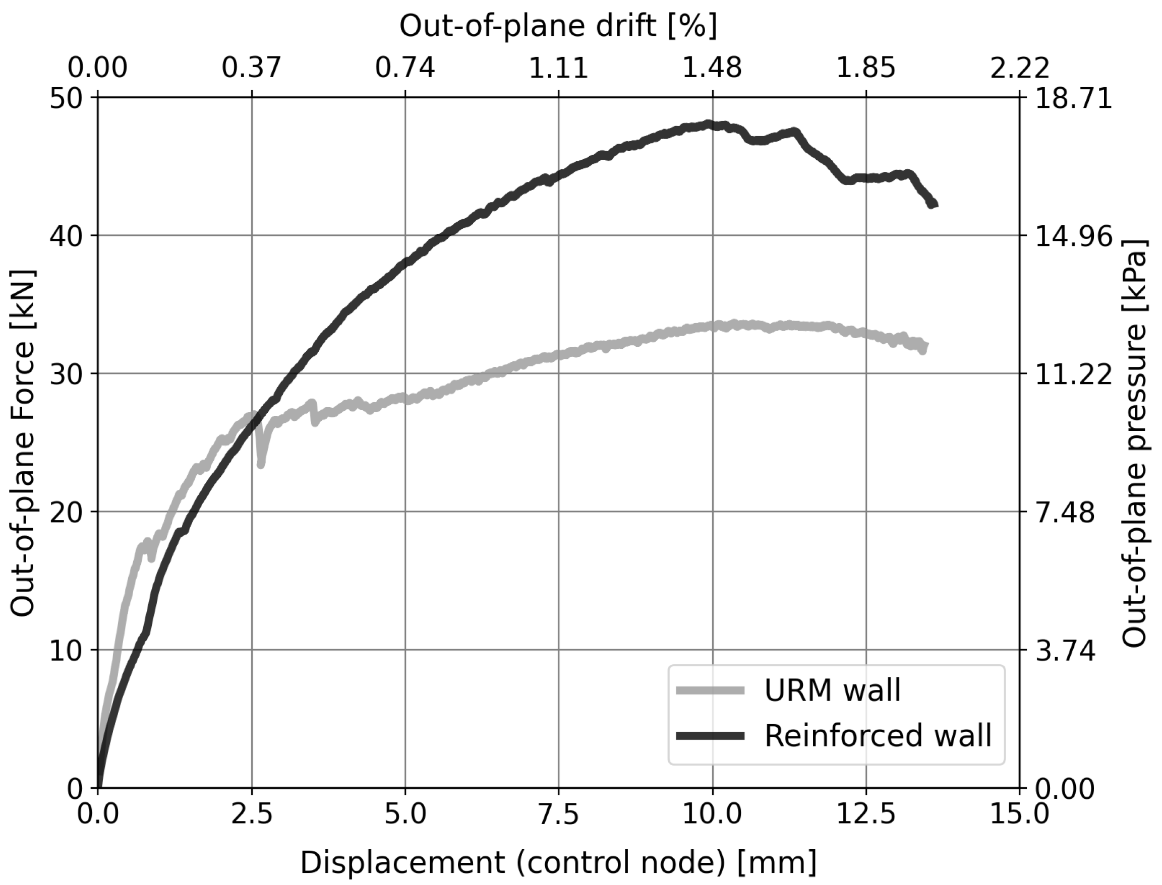
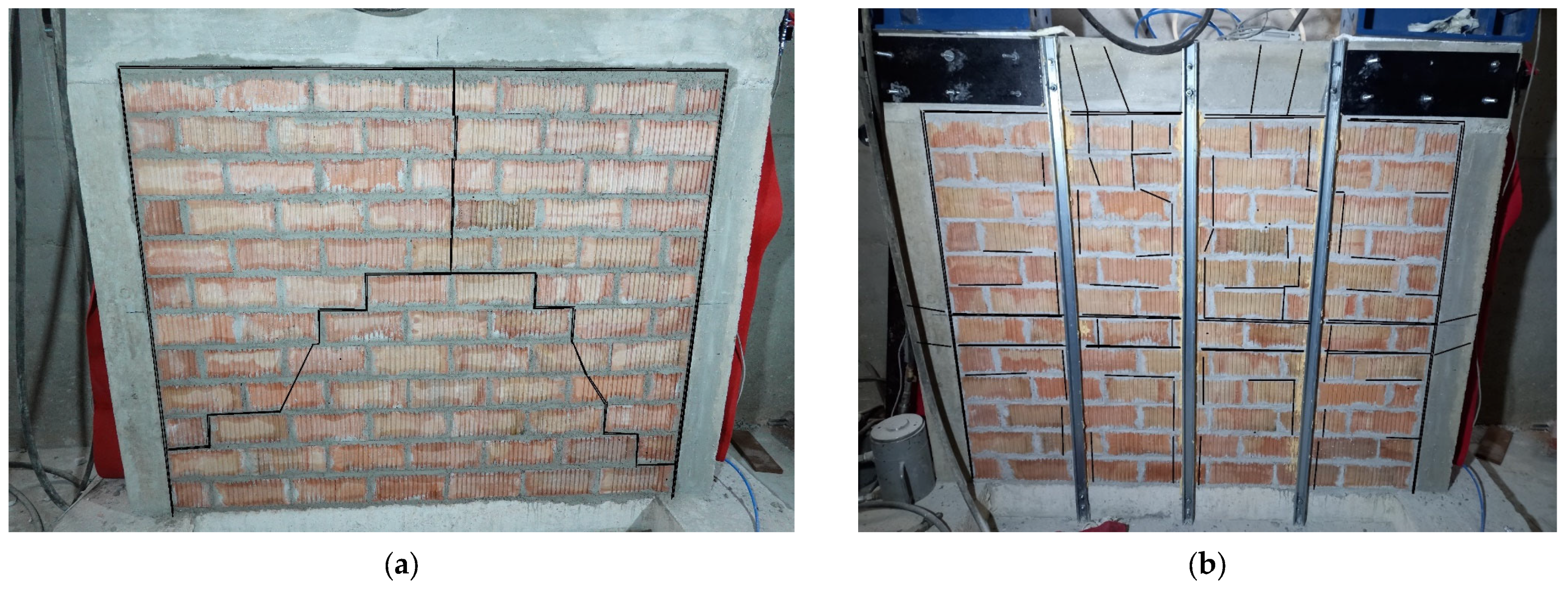
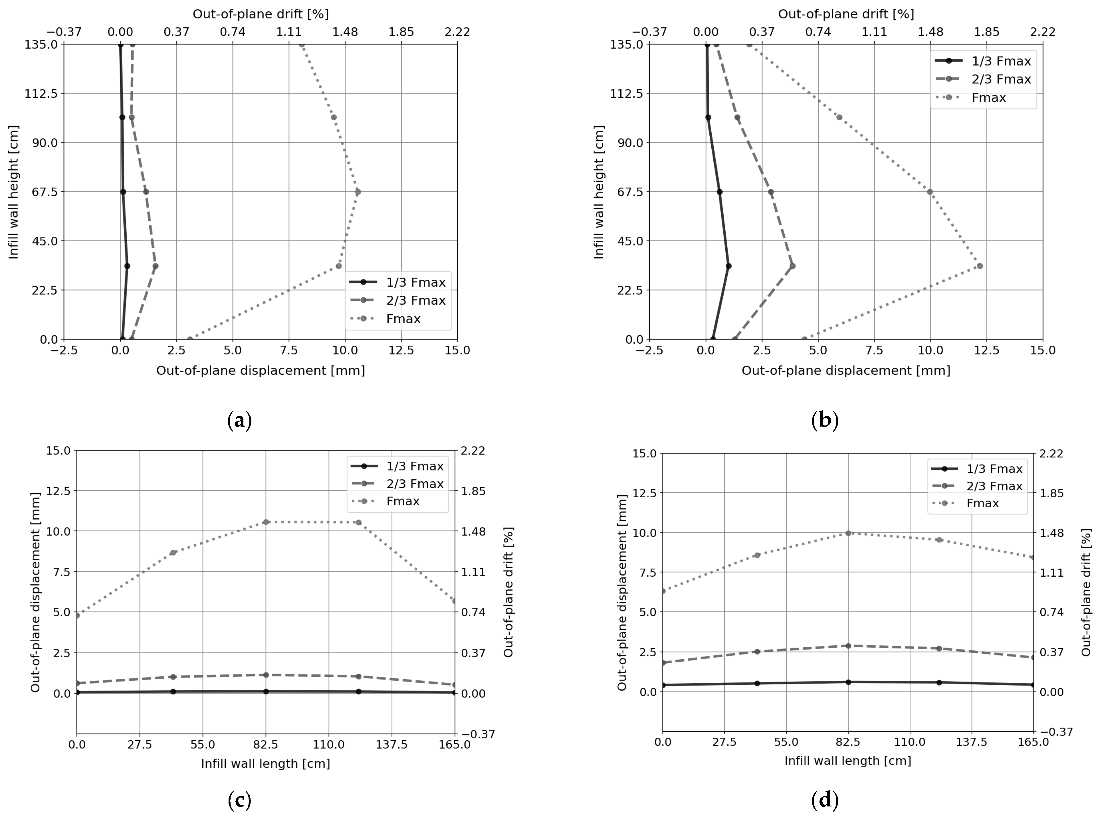
4.1.2. Seismic Performance of the Solution

The experimental results obtained from the tests are mainly in terms of force values, measured by the four load cells placed at the contrasting structure, and displacements assessed using the 13 LVDTs. The comparison between the load–displacement curves obtained from the two tests is shown in Figure 17. As can be observed, the structural renovation solution reinforcement solution considerably improved the out-of-plane capacity of the infill wall, achieving a 42% increase compared to the URM wall. The maximum strength occurred for an out-of-plane drift value of approximately 1.5%. Such a result makes the proposed solution promising for enhancing the seismic performance of masonry infill walls, allowing them to achieve higher force levels before collapsing. The difference in the initial stiffness was mainly due to residual plasticity effects on the RC frame from the first test, which did not prevent the subsequent improvement of the wall capacity. The reinforcement system made by the omega profiles became effective after an initial displacement of 1 mm at the control node in correspondence with a sudden change in the slope of the reinforced infill curve. At this displacement value, the URM wall response also presented a change from the initial linear trend, showing initial cracking after an out-of-plane drift of 0.2%. This was mainly due to the formation of the first cracks and the achievement of the plastic range in the masonry. Indeed, while the reinforced wall presented a subsequent increased stiffness due to the contribution of the strengthening system, the URM wall exhibited a lower slope due to the masonry cracking. After this threshold, a clear different behaviour between the two plots can be noticed: while the URM wall showed a horizontal plateau with almost constant force and increasing displacement, the reinforced structure still exhibited an increase in the applied out-of-plane force. After attaining the maximum capacity, the reinforced wall exhibited a gradual strength degradation, which can be explained by the failure mode, mainly attributed to the collapse of localised masonry (see below). It should be mentioned that the boundary conditions changed with this reinforcing solution since the steel profiles worked as additional constraints to the wall. Differently, in the URM infill, there were no constraints to the wall displacement except for the connection with the RC frame, which resulted in a weak restraint for this type of structure, as evidenced in seismic events and studies from the literature [84,86,87].
Concerning the cracking formation and failure mode, the URM wall presented a trilinear cracking pattern with deformations concentrated in the central point of the wall (see Figure 18a). A vertical mid-crack in the upper part (see Figure 19a) joined to two diagonal cracks from the bottom corners of the wall, dividing the infill into three main bodies. On the other side, the reinforced wall exhibited a different collapse mode, presenting visible horizontal cracks in the mid-span and the bottom part. Moreover, the retrofitted wall showed generalised cracking (see Figure 18b), mainly concentrated in correspondence with the omega profiles, as a consequence of the increased stiffness provided locally by the steel reinforcement. This was mainly due to the constraint provided by the steel reinforcement, which did not allow the free deformation of the masonry and also involved localised increases in the applied load. Finally, both the walls presented detachment at the boundaries with the surrounding elements (see Figure 19b), even if for the reinforced infill, this phenomenon was observed for higher load values due to the change in the static scheme of the structure.
Such observations further explain the wall responses reported in the load–displacement plot of Figure 17. In the curve representing the reinforced wall behaviour, the peak with the maximum applied force was followed by a softening phase, which was mainly due to generalised cracking in the masonry. On the other hand, such a trend was less visible for the URM wall due to the lower load applied and the response to the failure of the infill masonry. Indeed, due to detachment phenomena, the URM infill acted as a rigid body with very dangerous consequences in real practice (e.g., complete expulsion of the infill). This was not observed for the reinforced structure, which not only increased the out-of-plane capacity of the infill but also prevented a fragile collapse of the masonry.
Figure 20 shows the out-of-.plane displacement profiles of the URM and reinforced walls obtained from the experimental tests at increasing load according to the disposition of the LVDTs in the two main alignments (i.e., vertical and horizontal). It can be noticed that the detachment of the infill from the surrounding RC elements occurred in both tests. This confirms that the connection between the infill and the RC frame does not provide a suitable constraint against the out-of-plane collapse of masonry walls. This was more evident at the top beam compared to the foundation due to the self-weight of the masonry at the bottom part. However, from the comparison between the displacement profiles along the vertical alignment (see Figure 20a,b), the reinforcing system considerably reduced the out-of-plane displacement at the top of the wall. On the contrary, the strengthening solution was not able to limit the detachment at the columns due to its configuration, as can be seen from the displacement profiles along the horizontal alignment (see Figure 20c,d). Indeed, the vertical profiles were connected to the beam and the foundation, while there were no additional constraints between the infill and the RC columns. A possible solution could be to insert supplementary profiles closer to the columns to limit this issue and further increase the out-of-plane capacity of the reinforced wall. Alternatively, the addition of horizontal reinforcement would guarantee similar boundary conditions as for the top beam and foundation where a detachment of such magnitude was not observed.
In such a comparison between the URM and reinforced walls response, the considered loads are different since the maximum load supported by the infill was much higher in the second test with the strengthening system. This may explain the comparable values of displacements observed at the centre of the wall (see Figure 20a,b), which were achieved for much higher load values for the reinforced sample compared to the URM infill. Indeed, the former exhibited similar displacements for a load capacity Fmax which was 42% higher than the URM wall. In addition, it is interesting to note the beneficial effects of the solution, involving more concentrated displacement at the highest load levels, mainly due to local damages and masonry disgregation. Indeed, the higher force values possibly exceeded the strength of the masonry itself, which, in some cases, at the local level, presented high displacements due to this phenomenon (e.g., bottom quarter, see Figure 20b). On the contrary, the URM wall presented a more global failure mode that may involve higher safety risks. From the experimental assessment, the structural renovation solution improved the out-of-plane capacity of masonry infill walls with limited invasiveness and space required for the intervention. Such aspects may thus justify its application for the integrated seismic and energy retrofitting of RC-infilled frames in earthquake-prone areas.

4.2. Thermal Performance

The thermal performance of the building renovation model is the primary criterion for the renovation solution proposal. Hence, the renovation solution must comply with the Portuguese regulations for building façade thermal performance [88]. Therefore, the U-value of the renovation solution, together with the pre-existing façade, must be 0.35 W/m2·K or lower, and, at the same time, the pre-existing façade must be representative of the existing building stock in Portugal.

4.2.1. Thermal Performance of the 3D-Printed PET-G Panel

The 3D-printed polymer renovation solution’s configuration was defined in a previous study [18]. The optimal printing configuration for this specific purpose was two-layer perimeter printing with a 1.2 mm nozzle, and stars infill at 25% density. The printing configuration thermal resistance tests were conducted using the hotbox method by testing a 250 mm by 175 mm sample with 100 mm thickness, as shown in Figure 21.
The hotbox test chamber used was located in the Building Physics and Technology Laboratory, belonging to the Department of Civil Engineering of the University of Minho. It was built following ASTM C1363-11:2011 [89] and validated by Teixeira et al. [90]. The PET-G utilised is a Glacial White PET-G from the brand Winkle, printed by a Builder Extreme 1500 Pro, which was chosen due to its printing area and compatibility with the printed materials. The printer was equipped with a dual extruder direct drive printing head with a 1.2 mm nozzle being fed by two 8 kg 1.75 mm filament spools of the same material.
The R-value (thermal resistance) resulting from the experiment was 1.252 K·m2/W for the 100 mm of the sample, as specified, and a thermal conductivity of 0.079 W/m·K. This value is considered the thermal performance value of the 3D-printed PET-G for the following calculations of the panel module.

4.2.2. Renovation Solution Characterisation

The thermal performance of the renovation panel was assessed by calculating the assembled panel module thermal resistance (R-value) and the thermal transmittance (U-value) of the renovation solution integrated into a pre-existing façade representative of the Portuguese building stock.
The thermal performance of the designed renovation solution was calculated through equations 1 and 2 to achieve the solution’s total thermal resistance. It used the data obtained from the experiments to determine the total R-value and U-value of the whole renovation solution by adding the thermal resistance of a representative building façade in Portugal. The renovation panel composition is shown in Figure 22. Additional layers for the 86 mm and 111 mm models will add 4 mm of PET-G, 20 mm of agglomerated cork, and an additional 1 mm of closed airgap for the insulation fitting.
U v a l u e = 1 R t
R t = R s e + R 1 + R 2 + + R n + R s i
where:
  • Uvalue is the thermal transmittance in W/m2·K;
  • Rt is the total thermal resistance of the renovation panel + reference building façade;
  • Rse is the exterior surface thermal resistance in K·m2/W;
  • Rsi is the interior surface thermal resistance in K·m2/W;
  • R1 to n is the layer thermal resistance in K·m2/W.
Figure 22. 3D-printed panel wall composition for simulation in millimetres.
Sustainability 16 02166 g022
The values for agglomerated cork boards’ thermal resistance and density are defined by the official Portuguese document ITE50 [91], which has a thermal conductivity of 0.045 W/m·K and a thermal resistance of 0.484 K·m2/W for the 20 mm of each board considered for the renovation solution. Additionally, the addition of 1 mm of a closed airgap layer with a thermal conductivity of 0.025 W/m·K for the gaps between the agglomerated corkboard and hard shell was considered. The thermal 3D-printed PET-G with the discussed configuration has a thermal conductivity of 0.079 W/m·K and an R-value ranging from 0.050 K·m2/W to 0.063 K·m2/W for the 4 mm and 5 mm thicknesses, respectively. The TPU part of the panel was defined to be printed without infill, meaning that the TPU parts will be printed without the slicing software-generated internal geometry, resulting in a geometry with only the external perimeters. This printing configuration for the elastomeric elements results in a panel part that is printed with two 1.2 mm perimeters, resulting in a 4.8 mm thick TPU element with a 0.2 mm closed airgap interior, accounting for a 5 mm thick layer. Therefore, the thermal conductivity calculation considered the matweb database [57] for the thermoplastic elastomeric polyurethane, resulting in a thermal conductivity of 0.159 W/m·K and an R-value of 0.031 K·m2/W.
The following step was to add these renovation solutions to a reference building in Portugal. For that, it was considered a double-layer masonry 11 + 11 brick wall, with a 3 cm layer of extruded polystyrene (XPS) insulation in the air cavity, and plastered on both sides, with a total thickness of 30 cm. The façade is non-ventilated. The reference solution’s R-value is 1.19 K·m2/W and the U-value is 0.84 W/m2·K [91].

4.2.3. Thermal Performance Results

The R-values of the renovation modules are indicated in Table 5. The results point out a good thermal performance for these panels.
The results for the thermal transmittance (U-value) of the renovation panel and the renovation panel integrated into the reference building façade are shown in Table 6.
The 3D-printed panel module integrated into a building façade does accomplish the current Portuguese thermal performance requirements for a building façade of 0.35 W/m2·K [88]. Therefore, achieving the project’s target means developing a solution to address the thermal performance issues of the existing building stock in Portugal. The thinnest model, 61 mm, improved the pre-existing building façade thermal performance by 95%, improving the existent 0.84 W/m2·K to 0.43 W/m2·K. The 86 mm panel leads to an improvement of 140% and a U-value according to the legal requirements, improving the existent 0.84 W/m2·K to 0.35 W/m2·K. The 111 mm panel improved the building’s performance above the regulation requirements while improving the original façade by 180%, improving the existent 0.84 W/m2·K to 0.30 W/m2·K.
Notice that additional tests are necessary to evaluate and optimise the thermal performance of the panel in the connection areas between panels where the connection joint may pose a thermal bridge risk. If susceptible, the proposed renovation solution should be adapted to avoid thermal bridges. The durability and fire resistance of the panel must also be evaluated to determine the basic requirements for a façade renovation solution. Despite the limitations, the results achieved so far have paved the way for further research to integrate recycled plastic materials into building renovation solutions.
Overall, the renovation solution has the potential to improve the thermal performance of the existing building stock. Variations to the panel characteristics serve to optimise material consumption, taking into account renovation needs. It is possible to reduce the consumption of materials in buildings requiring less additional thermal resistance while improving low-performance buildings per the criteria defined in Portuguese regulations. Several other improvements can still be made to reduce material consumption and improve the overall thermal performance of the panel. Furthermore, research can be further explored by investigating other insulation materials that can contribute to a circular economy while providing better thermal performance. However, for a preliminary innovative research result, the thermal performance solution is satisfactory for the proposed research objectives of providing a renovation solution that improves the thermal performance of the existing building stock from a circular economy perspective in the construction sector.

5. Conclusions

This paper presents the development of a new prefabricated modular system, as a product developed within the nationally funded ZeroSkin+ project scope, tailored for renovating Portuguese residential building façades. The developed solution addresses building seismic performance and thermal efficiency. This study provides a detailed insight into the system’s potential to contribute to sustainable building retrofitting practices while serving as a stepping stone for future scientific development.
The integrated building renovation solution demonstrates how its modular system, which employs 3D-printed thermoplastics as a primary material, can improve the existing building stock’s thermal performance and seismic resilience. Its modular design, focused on disassembly and the ability to integrate recycled materials, also proposes a sustainable and circular way of rehabilitating the existing low-performing building stock.
Concerning the structural function, the experimental campaign has successfully demonstrated the benefits of the developed system. The seismic performance of the ZeroSkin+ solution, assured by the supporting steel frame structure, was assessed using half-scale RC frames to compare the structural response of infill walls with and without the proposed reinforcement. The experimental tests showed a 42% increase in the out-of-plane capacity of the reinforced infill compared to the URM wall, preventing a fragile collapse typical of such non-structural elements. Therefore, the performance of the ZeroSkin+ system in seismic conditions showed its potential as a retrofitting solution for RC-infilled frames, particularly in regions susceptible to earthquakes. This enhancement not only contributes to the safety and longevity of the building stock but also underscores the potential of modern manufacturing techniques in structural applications.
On the thermal front, the project’s achievements are equally commendable. By achieving a U-value as low as 0.30 W/m2·K in certain configurations, the 3D-printed panels exceed the standards required by current Portuguese legislation, demonstrating their ability to promote the reduction of energy consumption in renovated buildings. This level of performance reflects the system’s innovative design, which optimally balances thermal insulation with material efficiency and sustainability, presenting a viable solution to the challenge of improving the energy performance of existing buildings without compromising environmental sustainability.
Finally, the proposed integrated building renovation solution embodies the circular economy principles, highlighting an environmentally friendly approach to building renovation. Through the utilisation of recycled materials and a design that facilitates easy disassembly and recycling, the project sets a new standard for sustainable construction practices. This commitment to reducing waste and promoting reuse and recycling within the construction industry not only enhances the environmental performance of the renovation solution but also paves the way for future initiatives to achieve a more sustainable and resilient built environment.
Future research and development can be performed through further research on more suitable polymer materials which could even be recycled. The renovation solution’s long-term durability, fire performance, and cost-effectiveness could also be another improvement source.

Author Contributions

Conceptualization, L.L., L.P. and D.C.R.; Methodology, L.P. and D.C.R.; Investigation, L.L. and D.C.R.; Resources, M.A. and P.B.L.; Data curation, L.P. and D.V.O.; Writing—original draft, L.L., L.P. and D.C.R.; Writing—review & editing, M.A. and D.V.O.; Supervision, M.A., D.V.O. and P.B.L.; Project administration, D.C.R. and M.A.; Funding acquisition, P.B.L. All authors have read and agreed to the published version of the manuscript.

Funding

This work was partly financed by FCT/MCTES through national funds (PIDDAC) under the R&D Unit Institute for Sustainability and Innovation in Structural Engineering (ISISE), under reference UIDB/04029/2020 (https://doi.org/10.54499/UIDB/04029/2020) under the Associate Laboratory Advanced Production and Intelligent Systems ARISE under reference LA/P/0112/2020. The work was also partly financed by the program Portugal Norte 2020-Projetos Estruturados I&D, with the reference NORTE 01-0145-FEDER000058—ZeroSkin+ project. The support to the second author through grant agreement 2022.11827. BD, provided by the Portuguese Foundation for Science and Technology (FCT), is kindly acknowledged.

Institutional Review Board Statement

Not applicable.

Informed Consent Statement

Not applicable.

Data Availability Statement

The data presented in this study are available on request from the corresponding author.

Conflicts of Interest

The authors declare no conflict of interest.

References

  1. European Energy Council. Renovation Wave, Energy Efficient Buildings: Renovation Wave. Available online: https://energy.ec.europa.eu/topics/energy-efficiency/energy-efficient-buildings/renovation-wave_en (accessed on 7 February 2022).
  2. UNEP. 2022 Global Status Report for Buildings and Construction. Available online: www.globalabc.org (accessed on 29 November 2022).
  3. Energy Performance of Buildings Directive. Available online: https://energy.ec.europa.eu/topics/energy-efficiency/energy-efficient-buildings/energy-performance-buildings-directive_en (accessed on 20 November 2023).
  4. Reis, D.C.; De Domenico, A.T.; Lopes, L.; Almeida, M. Strategies and Actions for Achieving Carbon Neutrality in Portuguese Residential Buildings by 2050. Sustainability 2023, 15, 15626. [Google Scholar] [CrossRef]
  5. Lamego, P.; Lourenço, P.B.; Sousa, M.L.; Marques, R. Seismic vulnerability and risk analysis of the old building stock at urban scale: Application to a neighbourhood in Lisbon. Bull. Earthq. Eng. 2017, 15, 2901–2937. [Google Scholar] [CrossRef]
  6. Decreto-Lei n. 95/2019|DRE. Available online: https://dre.pt/dre/detalhe/decreto-lei/95-2019-123279819 (accessed on 12 April 2022).
  7. Marini, A.; Passoni, C.; Belleri, A.; Feroldi, F.; Preti, M.; Metelli, G.; Riva, P.; Giuriani, E.; Plizzari, G. Combining seismic retrofit with energy refurbishment for the sustainable renovation of RC buildings: A proof of concept. Eur. J. Environ. Civ. Eng. 2022, 26, 2475–2495. [Google Scholar] [CrossRef]
  8. Valluzzi, M.R.; Saler, E.; Vignato, A.; Salvalaggio, M.; Croatto, G.; Dorigatti, G.; Turrini, U. Nested buildings: An innovative strategy for the integrated seismic and energy retrofit of existing masonry buildings with CLT panels. Sustainability 2021, 13, 1188. [Google Scholar] [CrossRef]
  9. Busselli, M.; Cassol, D.; Prada, A.; Giongo, I. Timber based integrated techniques to improve energy efficiency and seismic behaviour of existing masonry buildings. Sustainability 2021, 13, 10379. [Google Scholar] [CrossRef]
  10. Almusaed, A.; Almssad, A.; Homod, R.Z.; Yitmen, I. Environmental Profile on Building Material Passports for Hot Climates. Sustainability 2020, 12, 3720. [Google Scholar] [CrossRef]
  11. Energy Agency, Net Zero by 2050—A Roadmap for the Global Energy Sector, 2050. Available online: www.iea.org/t&c/ (accessed on 1 March 2022).
  12. Minunno, R.; O’Grady, T.; Morrison, G.; Gruner, R.; Colling, M. Strategies for Applying the Circular Economy to Prefabricated Buildings. Buildings 2018, 8, 125. [Google Scholar] [CrossRef]
  13. Akanbi, L.A.; Oyedele, L.O.; Omoteso, K.; Bilal, M.; Akinade, O.O.; Ajayi, A.O.; Davila Delgado, J.M.; Owolabi, H.A. Disassembly and deconstruction analytics system (D-DAS) for construction in a circular economy. J. Clean. Prod. 2019, 223, 386–396. [Google Scholar] [CrossRef]
  14. Honic, M.; Kovacic, I.; Rechberger, H. Improving the recycling potential of buildings through Material Passports (MP): An Austrian case study. J. Clean. Prod. 2019, 217, 787–797. [Google Scholar] [CrossRef]
  15. Xue, H.; Zhang, S.; Su, Y.; Wu, Z.; Yang, R.J. Effect of stakeholder collaborative management on off-site construction cost performance. J. Clean. Prod. 2018, 184, 490–502. [Google Scholar] [CrossRef]
  16. Tam, V.W.Y.; Fung, I.W.H.; Sing, M.C.P.; Ogunlana, S.O. Best practice of prefabrication implementation in the Hong Kong public and private sectors. J. Clean. Prod. 2015, 109, 216–231. [Google Scholar] [CrossRef]
  17. Liu, G.; Li, K.; Zhao, D.; Mao, C. Business Model Innovation and Its Drivers in the Chinese Construction Industry during the Shift to Modular Prefabrication. J. Manag. Eng. 2016, 33, 04016051. [Google Scholar] [CrossRef]
  18. Lopes, L.; Reis, D.; Junior, A.P.; Almeida, M. Influence of 3D Microstructure Pattern and Infill Density on the Mechanical and Thermal Properties of PET-G Filaments. Polymers 2023, 15, 2268. [Google Scholar] [CrossRef]
  19. de Rubeis, T. 3D-Printed Blocks: Thermal Performance Analysis and Opportunities for Insulating Materials. Sustainability 2022, 14, 1077. [Google Scholar] [CrossRef]
  20. Shen, Y.; Zhang, D.; Wang, R.; Li, J.; Huang, Z. SBD-K-medoids-based long-term settlement analysis of shield tunnel. Transp. Geotech. 2023, 42, 101053. [Google Scholar] [CrossRef]
  21. Nguyen, P.D.; Nguyen, T.Q.; Tao, Q.B.; Vogel, F.; Nguyen-Xuan, H. A data-driven machine learning approach for the 3D printing process optimisation. Virtual Phys. Prototyp. 2023, 17, 768–786. [Google Scholar] [CrossRef]
  22. ZeroSkin+—A Building Renovation Project Using Recycled Plastic by University of Minho. Available online: https://civil.uminho.pt/zeroskin/index.html (accessed on 16 February 2024).
  23. Ademovic, N.; Formisano, A.; Penazzato, L.; Oliveira, D.V. Seismic and energy integrated retrofit of buildings: A critical review. Front. Built Environ. 2022, 8, 963337. [Google Scholar] [CrossRef]
  24. Furtado, A.; Rodrigues, H.; Arêde, A. Experimental study of the flexural strength of masonry brick walls strengthened with thermal insulation. Constr. Build. Mater. 2023, 401, 132934. [Google Scholar] [CrossRef]
  25. Triantafillou, T.C.; Karlos, K.; Kefalou, K.; Argyropoulou, E. An innovative structural and energy retrofitting system for URM walls using textile reinforced mortars combined with thermal insulation: Mechanical and fire behavior. Constr. Build. Mater. 2017, 133, 1–13. [Google Scholar] [CrossRef]
  26. Artino, A.; Evola, G.; Margani, G.; Marino, E.M. Seismic and energy retrofit of apartment buildings through autoclaved aerated concrete (AAC) blocks infill walls. Sustainability 2019, 11, 3939. [Google Scholar] [CrossRef]
  27. de Sousa, C.; Barros, J.A.O.; Correia, J.R.; Valente, T.D.S. Development of sandwich panels for multi-functional strengthening of RC buildings: Characterisation of constituent materials and shear interaction of panel assemblies. Constr. Build. Mater. 2021, 267, 120849. [Google Scholar] [CrossRef]
  28. Vanegas, P.; Peeters, J.R.; Cattrysse, D.; Tecchio, P.; Ardente, F.; Mathieux, F.; Dewulf, W.; Duflou, J.R. Ease of disassembly of products to support circular economy strategies. Resour. Conserv. Recycl. 2018, 135, 323–334. [Google Scholar] [CrossRef]
  29. O’Grady, T.; Minunno, R.; Chong, H.Y.; Morrison, G.M. Design for disassembly, deconstruction and resilience: A circular economy index for the built environment. Resour. Conserv. Recycl. 2021, 175, 105847. [Google Scholar] [CrossRef]
  30. Minunno, R.; O’Grady, T.; Morrison, G.M.; Gruner, R.L. Exploring environmental benefits of reuse and recycle practices: A circular economy case study of a modular building. Resour. Conserv. Recycl. 2020, 160, 104855. [Google Scholar] [CrossRef]
  31. MacKenbach, S.; Zeller, J.C.; Osebold, R. A Roadmap towards Circularity—Modular Construction as a Tool for Circular Economy in the Built Environment. IOP Conf. Ser. Earth Environ. Sci. 2020, 588, 052027. [Google Scholar] [CrossRef]
  32. Strauß, H.; Knaack, U. Additive Manufacturing for Future Facades: The potential of 3D printed parts for the building envelope. J. Facade Des. Eng. 2016, 3, 225–235. [Google Scholar] [CrossRef]
  33. Grassi, G.; Spagnolo, S.L.; Paoletti, I. Fabrication and durability testing of a 3D printed façade for desert climates. Addit. Manuf. 2019, 28, 439–444. [Google Scholar] [CrossRef]
  34. Atakok, G.; Kam, M.; Koc, H.B. A Review of Mechanical and Thermal Properties of Products Printed with Recycled Filaments for Use in 3D Printers. Surf. Rev. Lett. 2021, 29, 1–18. [Google Scholar] [CrossRef]
  35. Fico, D.; Rizzo, D.; Casciaro, R.; Corcione, C.E. A Review of Polymer-Based Materials for Fused Filament Fabrication (FFF): Focus on Sustainability and Recycled Materials. Polymers 2022, 14, 465. [Google Scholar] [CrossRef]
  36. Reich, M.J.; Woern, A.L.; Tanikella, N.G.; Pearce, J.M. Mechanical properties and applications of recycled polycarbonate particle material extrusion-based additive manufacturing. Materials 2019, 12, 1642. [Google Scholar] [CrossRef]
  37. Silva, V.; Crowley, H.; Varum, H.; Pinho, R. Seismic risk assessment for mainland Portugal. Bull. Earthq. Eng. 2015, 13, 429–457. [Google Scholar] [CrossRef]
  38. Luján, S.V.; Arrebola, C.V.; Sánchez, A.R.; Benito, P.A.; Cortina, M.G. Experimental comparative study of the thermal performance of the façade of a building refurbished using ETICS, and quantification of improvements. Sustain. Cities Soc. 2019, 51, 101713. [Google Scholar] [CrossRef]
  39. Pihelo, P.; Kalamees, T.; Kuusk, K. NZEB Renovation with Prefabricated Modular Panels. In Energy Procedia; Elsevier Ltd.: Amsterdam, The Netherlands, 2017; pp. 1006–1011. [Google Scholar] [CrossRef]
  40. Sousa, J. Application of prefabricated panels for the energy retrofit of Portuguese residential buildings facades: A case study. Arch. Civ. Eng. 2013, 59, 337–357. [Google Scholar] [CrossRef]
  41. Almeida, M.; Barbosa, R.; Malheiro, R. Effect of embodied energy on cost-effectiveness of a prefabricated modular solution on renovation scenarios in social housing in Porto, Portugal. Sustainability 2020, 12, 1631. [Google Scholar] [CrossRef]
  42. Szykiedans, K.; Credo, W.; Osiński, D. Selected Mechanical Properties of PETG 3-D Prints. Procedia Eng. 2017, 177, 455–461. [Google Scholar] [CrossRef]
  43. Holcomb, G.; Caldona, E.B.; Cheng, X.; Advincula, R.C. On the soptimised 3D printing and post-processing of PETG materials. MRS Commun. 2022, 12, 381–387. [Google Scholar] [CrossRef]
  44. Sarakinioti, M.V.; Turrin, M.; Konstantinou, T.; Tenpierik, M.; Knaack, U. Developing an integrated 3D-printed façade with complex geometries for active temperature control. Mater. Today Commun. 2018, 15, 275–279. [Google Scholar] [CrossRef]
  45. Piccioni, V.; Leschok, M.; Grobe, L.O.; Wasilewski, S.; Seshadri, B.; Hischier, I.; Schlüter, A. Tuning the Solar Performance of Building Facades through Polymer 3D Printing: Toward Bespoke Thermo-Optical Properties. Adv. Mater. Technol. 2023, 8, 2201200. [Google Scholar] [CrossRef]
  46. Latko-Durałek, P.; Dydek, K.; Boczkowska, A. Thermal, Rheological and Mechanical Properties of PETG/rPETG Blends. J. Polym. Environ. 2019, 27, 2600–2606. [Google Scholar] [CrossRef]
  47. Yan, C.; Kleiner, C.; Tabigue, A.; Shah, V.; Sacks, G.; Shah, D.; DeStefano, V. PETG: Applications in Modern Medicine. Eng. Regen. 2024, 5, 45–55. [Google Scholar] [CrossRef]
  48. Frick, A.; Rochman, A. Characterisation of TPU-elastomers by thermal analysis (DSC). Polym. Test. 2004, 23, 413–417. [Google Scholar] [CrossRef]
  49. Herrera, M.; Matuschek, G.; Kettrup, A. Thermal degradation of thermoplastic polyurethane elastomers (TPU) based on MDI. Polym. Degrad. Stab. 2002, 78, 323–331. [Google Scholar] [CrossRef]
  50. Schweitzer, P.A. Mechanical and Corrosion-Resistant Properties of Plastics and Elastomers. In Mechanical and Corrosion-Resistant Properties of Plastics and Elastomers; CRC Press: Boca Raton, FL, USA, 2000. [Google Scholar] [CrossRef]
  51. Boubakri, A.; Haddar, N.; Elleuch, K.; Bienvenu, Y. Impact of aging conditions on mechanical properties of thermoplastic polyurethane. Mater. Des. 2010, 31, 4194–4201. [Google Scholar] [CrossRef]
  52. Tártaro, A.S.; Mata, T.M.; Martins, A.A.; da Silva, J.C.G.E. Carbon footprint of the insulation cork board. J. Clean. Prod. 2017, 143, 925–932. [Google Scholar] [CrossRef]
  53. Barreca, F.; Fichera, C.R. Thermal Insulation Performance Assessment Of Agglomerated Cork Boards. Wood Fiber Sci. 2016, 48, 96–103. [Google Scholar]
  54. Instituto Português do Mar e da Atmosfera. Available online: https://www.ipma.pt/pt/oclima/extremos.clima/ (accessed on 4 February 2024).
  55. Overview of Materials for PETG Copolyester. Available online: https://www.matweb.com/search/datasheettext.aspx?matguid=4de1c85bb946406a86c52b688e3810d0/ (accessed on 4 February 2024).
  56. Dupaix, R.B.; Boyce, M.C. Finite strain behavior of poly(ethylene terephthalate) (PET) and poly(ethylene terephthalate)-glycol (PETG). Polymer 2005, 46, 4827–4838. [Google Scholar] [CrossRef]
  57. Overview of Materials for Thermoplastic Polyurethane, Elastomer, Polyester Grade. Available online: https://www.matweb.com/search/datasheettext.aspx?matguid=9f5318a1f93b403bbd5748abec70fac1/ (accessed on 4 February 2024).
  58. Nguyen, K.T.; Weerasinghe, P.; Mendis, P.A.; Ngo, T.D. Performance of modern building façades in fire: A comprehensive review. Electron. J. Struct. Eng. 2016, 16, 69–87. [Google Scholar] [CrossRef]
  59. Moghtadernejad, S.; Mirza, M.S.; Chouinard, L.E. Façade Design Stages: Issues and Considerations. J. Archit. Eng. 2019, 25, 04018033. [Google Scholar] [CrossRef]
  60. Chatterjee, S.; Shanmuganathan, K.; Kumaraswamy, G. Fire-Retardant, Self-Extinguishing Inorganic/Polymer Composite Memory Foams. ACS Appl. Mater. Interfaces 2017, 9, 44864–44872. [Google Scholar] [CrossRef]
  61. EN 13501-1+A1; Fire Classification of Construction Products and Building Elements—Part 1: Classification Using Test Data from Reaction to Fire Tests. European Standards: Brussels, Belgium, 2018. Available online: https://www.en-standard.eu/ilnas-en-13501-1-a1-fire-classification-of-construction-products-and-building-elements-part-1-classification-using-test-data-from-reaction-to-fire-tests-1/ (accessed on 7 February 2022).
  62. Guo, Y.; Ruan, K.; Shi, X.; Yang, X.; Gu, J. Factors affecting thermal conductivities of the polymers and polymer composites: A review. Compos. Sci. Technol. 2020, 193, 108134. [Google Scholar] [CrossRef]
  63. Hsissou, R.; Seghiri, R.; Benzekri, Z.; Hilali, M.; Rafik, M.; Elharfi, A. Polymer composite materials: A comprehensive review. Compos. Struct. 2021, 262, 113640. [Google Scholar] [CrossRef]
  64. Silva, P.C.P.; Almeida, M.; Bragança, L.; Mesquita, V. Development of prefabricated retrofit module towards nearly zero energy buildings. Energy Build. 2013, 56, 115–125. [Google Scholar] [CrossRef]
  65. Sebastian, R.; Gralka, A.; Olivadese, R.; Arnesano, M.; Revel, G.M.; Hartmann, T.; Gutsche, C. Plug-and-Play Solutions for Energy-Efficiency Deep Renovation of European Building Stock. Proceedings 2018, 2, 1157. [Google Scholar] [CrossRef]
  66. Tam, V.W.Y.; Tam, C.M.; Zeng, S.X.; Ng, W.C.Y. Towards adoption of prefabrication in construction. Build. Environ. 2007, 42, 3642–3654. [Google Scholar] [CrossRef]
  67. Navaratnam, S.; Ngo, T.; Gunawardena, T.; Henderson, D. Performance Review of Prefabricated Building Systems and Future Research in Australia. Buildings 2019, 9, 38. [Google Scholar] [CrossRef]
  68. Katrien, M.; Stéphanie, V.L.; Koen, V.; Den, V.; Nathan, B.; Marijke, S. Air-and water tightness of prefabricated envelope modules for the renovation of buildings. In Proceedings of the 14th International Conference on Durability of Building Materials and Components (XIV DBMC), Ghent, Belgium, 29–31 May 2017. [Google Scholar]
  69. Lopez, D.; Froese, T.M. Analysis of Costs and Benefits of Panelized and Modular Prefabricated Homes. Procedia Eng. 2016, 145, 1291–1297. [Google Scholar] [CrossRef]
  70. Rovers, R.; Zikmund, A.; Lupisek, A.; Borodinecs, A. A Guide into Renovation Package Concepts for Mass Retrofit of Different Types of Buildings with Prefabrication Elements for nZEB Performance; University of Minho: Braga, Portugal, 2018. [Google Scholar]
  71. Pihelo, P.; Lelumees, M.; Kalamees, T. Influence of Moisture Dry-out on Hygrothermal Performance of Prefabricated Modular Renovation Elements. In Energy Procedia; Elsevier Ltd.: Amsterdam, The Netherlands, 2016; pp. 745–755. [Google Scholar] [CrossRef]
  72. Orlowski, K.; Shanaka, K.; Mendis, P. Design and Development of Weatherproof Seals for Prefabricated Construction: A Methodological Approach. Panelized Composite Timber Wall System for Prefabricated Buildings View project Design and Development of Weatherproof Seals for Prefabricated Construction: A Methodological Approach. Buildings 2018, 8, 117. [Google Scholar] [CrossRef]
  73. Hirschler, M.M. Façade requirements in the 2021 edition of the US International Building Code. Fire Mater. 2021, 45, 586–597. [Google Scholar] [CrossRef]
  74. Diário da Républica. Portaria n. 98/2019 de 2 de Abril; Diário da Républica: Portaria, Greece, 2019; pp. 1816–1818. [Google Scholar]
  75. Stoof, D.; Pickering, K. Sustainable composite fused deposition modelling filament using recycled pre-consumer polypropylene. Compos. B Eng. 2018, 135, 110–118. [Google Scholar] [CrossRef]
  76. Van De Voorde, B.; Katalagarianakis, A.; Huysman, S.; Toncheva, A.; Raquez, J.-M.; Duretek, I.; Holzer, C.; Cardon, L.; Bernaerts, K.V.; Van Hemelrijck, D.; et al. Effect of extrusion and fused filament fabrication processing parameters of recycled poly(ethylene terephthalate) on the crystallinity and mechanical properties. Addit. Manuf. 2022, 50, 102518. [Google Scholar] [CrossRef]
  77. Gradus, R. Postcollection Separation of Plastic Recycling and Design-For-Recycling as Solutions to Low Cost-Effectiveness and Plastic Debris. Sustainability 2020, 12, 8415. [Google Scholar] [CrossRef]
  78. Khosravani, M.R.; Reinicke, T. On the environmental impacts of 3D printing technology. Appl. Mater. Today 2020, 20, 100689. [Google Scholar] [CrossRef]
  79. Cerdas, F.; Juraschek, M.; Thiede, S.; Herrmann, C. Life Cycle Assessment of 3D Printed Products in a Distributed Manufacturing System. J. Ind. Ecol. 2017, 21, S80–S93. [Google Scholar] [CrossRef]
  80. Nguyen, N.D.; Ashraf, I.; Kim, W. Compact Model for 3D Printer Energy Estimation and Practical Energy-Saving Strategy. Electronics 2021, 10, 483. [Google Scholar] [CrossRef]
  81. Vidakis, N.; Kechagias, J.D.; Petousis, M.; Vakouftsi, F.; Mountakis, N. The effects of FFF 3D printing parameters on energy consumption. Mater. Manuf. Process. 2023, 38, 915–932. [Google Scholar] [CrossRef]
  82. Al Rashid, A.; Koç, M. Additive manufacturing for sustainability and circular economy: Needs, challenges, and opportunities for 3D printing of recycled polymeric waste. Mater. Today Sustain. 2023, 20, 100529. [Google Scholar] [CrossRef]
  83. EN 1998-1 (2004); Eurocode 8: Design of Structures for Earthquake Resistance-Part 1: General Rules, Seismic Actions and Rules for Buildings. European Standards: Brussels, Belgium, 1998.
  84. Furtado, A.; Rodrigues, H.; Arêde, A.; Varum, H. Experimental evaluation of out-of-plane capacity of masonry infill walls. Eng. Struct. 2016, 111, 48–63. [Google Scholar] [CrossRef]
  85. Akhoundi, F.; Silva, L.M.; Vasconcelos, G.; Lourenço, P. Out-of-Plane Strengthening of Masonry Infills Using Textile Reinforced Mortar (TRM) Technique. Int. J. Archit. Herit. 2023, 17, 310–325. [Google Scholar] [CrossRef]
  86. Ricci, P.; de Luca, F.; Verderame, G.M. 6th April 2009 LAquila earthquake, Italy: Reinforced concrete building performance. Bull. Earthq. Eng. 2011, 9, 285–305. [Google Scholar] [CrossRef]
  87. Ceci, A.M.; Contento, A.; Fanale, L.; Galeota, D.; Gattulli, V.; Lepidi, M.; Potenza, F. Structural performance of the historic and modern buildings of the University of LAquila during the seismic events of April 2009. Eng. Struct. 2010, 32, 1899–1924. [Google Scholar] [CrossRef]
  88. Diário da República. Decreto-Lei n. 102/2021, de 19 de Novembro; Presidência do Conselho de Ministros: Lisbon, Portugal, 2021; pp. 6–15. [Google Scholar]
  89. ASTM C1363-11; Standard Test Method for Thermal Performance of Building Materials and Envelope Assemblies by Means of a Hot Box Apparatus. ASTM International: West Conshohocken, PA, USA, 2024. Available online: https://www.astm.org/c1363-11.html (accessed on 16 February 2024).
  90. Teixeira, E.R.; Machado, G.; Junior, A.d.P.; Guarnier, C.; Fernandes, J.; Silva, S.M.; Mateus, R. Mechanical and Thermal Performance Characterisation of Compressed Earth Blocks. Energies 2020, 13, 2978. [Google Scholar] [CrossRef]
  91. Santos, P.D.; Matias, L. ITE50; ICT Informação Técnica: Cesano Maderno, Italy, 2006. [Google Scholar]
Figure 1. Proposed renovation solution development flowchart.
Sustainability 16 02166 g001
Figure 2. A visual representation of the steel structure attached to an infill wall.
Sustainability 16 02166 g002
Figure 3. Renovation panel parts are illustrated.
Sustainability 16 02166 g003
Figure 4. 3D-printed building renovation panel connection design to the structural grid in millimetres.
Sustainability 16 02166 g004
Figure 5. 3D-printing infill geometry optimisation chart, adapted from [18].
Sustainability 16 02166 g005
Figure 6. 3D-printed building renovation panel sections show the alternative thicknesses and different compositions of the insulation space in between modules in millimetres.
Sustainability 16 02166 g006
Figure 7. (a) Wavy patterns of the renovation panel to avoid structural issues when printing a thin wall with PET-G. (b) The panel prototype displays the wavy pattern of the internal walls.
Sustainability 16 02166 g007
Figure 8. (a) Section of the 3D model showing the triangular internal structure of the elastomeric polymer belt. (b) Elastomeric polymer parts, belt, and back panel are highlighted in red.
Sustainability 16 02166 g008
Figure 9. Panel module assembly illustration with the assembly steps order marked from 1 to 4.
Sustainability 16 02166 g009
Figure 10. Representation of RC frame geometry and elements dimensions.
Sustainability 16 02166 g010
Figure 11. RC frame: reinforcement disposition.
Sustainability 16 02166 g011
Figure 12. URM infill wall testing: (a) Infill wall out-of-plane test setup (front side view); (b) test setup for applying load and contrasting structures (side view).
Sustainability 16 02166 g012
Figure 13. Schematic representation of the test setup layout and the LVDTs location.
Sustainability 16 02166 g013
Figure 14. Structural reinforcement: (a) omega section dimensions (half-scale); (b) view of the steel profile.
Sustainability 16 02166 g014
Figure 15. Schematic representation of the reinforced infill wall with omega profiles.
Sustainability 16 02166 g015
Figure 16. Reinforced infill wall: (a) overview of the infill wall reinforced by the structural renovation solution; (b) detail of the anchorage system between the omega profile and foundation.
Sustainability 16 02166 g016
Figure 17. Load–displacement curves obtained from experimental testing on URM and reinforced infill walls.
Sustainability 16 02166 g017
Figure 18. Observed damage in the URM infill wall: cracking pattern of (a) URM wall and (b) reinforced infill.
Sustainability 16 02166 g018
Figure 19. Infill wall damage: (a) vertical crack (URM wall); (b) detachment from lateral column (reinforced wall).
Sustainability 16 02166 g019
Figure 20. Out-of-plane displacement profiles: vertical alignment of (a) URM wall and (b) reinforced infill; horizontal alignment of (c) URM wall and (d) reinforced infill.
Sustainability 16 02166 g020
Figure 21. (a) 3D-printed 100 mm thick sample of the printing configuration of the PET-G filament with the 25% stars infill. (b) The 3D-printed sample is in the hotbox.
Sustainability 16 02166 g021
Table 1. Selected plastic materials’ characteristics according to the proposed requirements for the material renovation panel.
MaterialPET-GTPU
Extrusion temperature220 °C to 260 °C210 °C to 230 °C
Glass transition temperature80 °C−21.8 °C
Melting temperature160 °C192 °C
UV resistantHighly resistantColour deterioration with small mechanical deterioration
FlammabilityFlammable, can be fire resistant with additivesFlammable, can be fire resistant with additives
ToxicityNon-toxicCan release toxic fumes when burned
RecyclabilityRecyclableRecyclable
Table 2. PET-G 3D-printing parameters used for the renovation solution manufacturing.
ParametersAdopted Values
Nozzle Diameter1.2 mm
Extrusion Diameter1.26 mm
First Layer Height0.45 mm
Layer Height0.60 mm
Print Speed70 mm/s
Retraction Distance7 mm
Retraction Speed40 mm/s
Printing Temperature250 °C
Printing Bed Temperature60 °C
Table 3. PET-G panel weight per m2.
ModelPET-GPrinting Time per 3D Printer
61 mm12.24 kg/m2118 h/m2
86 mm15.36 kg/m2184 h/m2
111 mm18.21 kg/m2202 h/m2
Table 4. Elastomeric plastic 3D-printing characteristics.
ParametersTPU
Printing Speed30 mm/s
Retraction Distance9 mm
Retraction Speed50 mm/s
Printing Temperature230 °C
ModelTPU weightPrinting time
61 mm1.39 kg/m250 h
86 mm1.64 kg/m256 h
111 mm1.87 kg/m263 h
Table 5. Renovation panel module R-values.
ModelR-Value
61 mm1.14 K·m2/W
86 mm1.63 K·m2/W
111 mm2.13 K·m2/W
Table 6. Thermal transmittance (U-value) of the renovation panel (alone and integrated into a building façade).
Panel ModelU-Value
3D-Printed Panel Alone
W/m2·K
U-Value
3D-Printed Panel + Building Façade
W/m2·K
61 mm0.870.43
86 mm0.610.35
111 mm0.470.30
Disclaimer/Publisher’s Note: The statements, opinions and data contained in all publications are solely those of the individual author(s) and contributor(s) and not of MDPI and/or the editor(s). MDPI and/or the editor(s) disclaim responsibility for any injury to people or property resulting from any ideas, methods, instructions or products referred to in the content.

