
Simplified Criterion for Low Gravity Center Cable-Stayed Bridge Based on Response Spectrum Analyses

Key Laboratory of Earthquake Engineering and Structural Retrofit of Beijing, Department of Civil Engineering, Beijing University of Technology, No.100 Ping Leyuan, Chaoyang District, Beijing 100124, China
*
Author to whom correspondence should be addressed.
Sustainability 2022, 14(17), 10570; https://doi.org/10.3390/su141710570
Submission received: 19 July 2022
/
Revised: 13 August 2022
/
Accepted: 17 August 2022
/
Published: 24 August 2022
Abstract
:The seismic response characteristics of a cable-stayed bridge are closely related to the structural system. At the same time, the influence of the height of the gravity center cannot be ignored in the structural system selection of cable-stayed bridges. For convenience, to make the scheme comparison and structural system selection in the preliminary design stage of a cable-stayed bridge, the judgment criterion of a low gravity center cable-stayed bridge was proposed, based on the simplified calculation of the fundamental frequency of cable-stayed bridges with two kinds of the structural system and combined with the response spectrum analysis method. The comparison of the results of the finite element model and the calculating results of the criterion showed that the judgment criterion has high accuracy and reliability, and can be applied to the preliminary design, the scheme comparison of cable-stayed bridges, and help select structural systems in the preliminary design stage of cable-stayed bridges.
1. Introduction
Cable-stayed bridges are widely used in long-span bridges with their unique structural system [1,2,3], and the seismic design is an essential part of the design of cable-stayed bridges [4,5]. There are many factors affecting the shock resistance performance of the cable bridge. For example, based on finite element simulation and vibration platform test research, Zhang et al. analyzed the lateral seismic fragility of a cable-stayed bridge with diamond-shaped pylons [6,7,8]. The results imply that the failure modes and damage regions of the bridge would be changed with the pylon shapes, stiffness of lower and middle crossbeams, and loading protocols. So, selecting an excellent structural system according to site type and structural characteristics is very important to the seismic performance of cable-stayed bridges. The structural system of the cable-stayed bridge can be divided into a floating system, longitudinal hinge system, and combined system according to different connection modes of girder and tower. Existing studies show that the floating system has low longitudinal stiffness and is a long-period structure [9,10]. Under seismic loads, the internal force response of the tower control section is small. The full floating system can effectively reduce the seismic internal force demand of the tower control section of the cable-stayed bridge. However, at the same time, it will also cause a large displacement response in an earthquake [11]. On the contrary, the longitudinal rigidity of the longitudinally hinged cable-stayed bridge is large [12], which can effectively control the longitudinal displacement response of the main girder and the tower under the seismic load, but the tower controls the internal force response of the section more. The combined system adds special restraint devices (such as elastic restraint cables or dampers) to the floating system, which can improve the seismic performance of the cable-stayed bridge [13,14], but it will also make the seismic design of the cable-stayed bridge more complicated [15].
However, the above studies are all based on traditional cable-stayed bridges, and the influence of the height of the center of gravity on the seismic response characteristics of cable-stayed bridges is ignored. For conventional cable-stayed bridges, the control of the internal force response and displacement response in an earthquake is contradictory. With economic development and construction technology innovation, more and more cable-stayed bridges are used in cities and non-navigable rivers. Since these cable-stayed bridges do not require too much clearance under the bridge, the height of the main girder can be reduced, thereby reducing the overall center of gravity of the cable-stayed bridge. According to the seismic inertial force transmission path proposed by Zhang et al. [12], for the floating system cable-stayed bridge, the transmission path of the seismic inertial force of the main girder and the bridge deck system is: → stayed cable → main tower; at this time, as the longitudinal period of the structure becomes longer, the horizontal inertia force is smaller than that of the longitudinal restraint structure system, but the arm of on the tower bottom becomes larger, so the tower bottom bending moment of the floating system cable-stayed bridge may not be small. The horizontal inertial force of the tower beam longitudinal restraint system increases very little compared with that of the floating system when the first-order longitudinal vibration period of the tower beam longitudinal restraint system structure is still located in the gentle zone of the response spectrum. For cable-stayed bridges with very low main girder height, the bending moment at the bottom of the floating system may be larger than that of the longitudinal hinged system. This leads to the concept of a low center of gravity cable-stayed bridge [9], which is the ratio of tower bottom bending moment calculated according to the floating system under a given seismic load to the tower bottom bending moment calculated according to the longitudinal hinged system .
Zhang et al. researched a single-tower low center of gravity cable-stayed bridge [16], and the results showed that the bending moments at each control section of the main tower of the longitudinal hinged system are significantly smaller than those of the floating structure system. The studies by Zhao et al. and Camara et al. have proved that the bridge deck’s height significantly impacts the seismic performance of cable-stayed bridges [17,18]. The seismic performance study of low-center cable-stayed bridges through shaking table experiments by Zhang et al. proved that using a fixed hinge system for the low gravity center cable-stayed bridges can reduce earthquake damage in strong earthquakes [19].
The preliminary studies show that the longitudinal hinged system may solve the contradictory problem of controlling internal force response and displacement response in the seismic design of cable-stayed bridges for low gravity center cable-stayed bridges. So, it is important to determine whether the bridge belongs to a low-gravity cable-stayed bridge or not before the selection of the seismic structural system. The seismic response, such as tower bottom bending moments of a cable-stayed bridge with a different seismic structural system, can usually be obtained through finite element analysis or a shaking table test [12,20,21,22,23,24]. At the same time, both are very time-consuming and energy-consuming [25], especially when various parameters need to be adjusted in the early design stage, which is not conducive to the initial design.
Therefore, it is significant to derive a simplified discriminant formula for low-gravity cable-stayed bridges. In the seismic response of cable-stayed bridges, the contribution rate of the first-order longitudinal vibration mode shape is dominant [26], and the bending moment of the tower bottom under the seismic load can be calculated by solving the natural frequency of the cable-stayed bridge. For the model simplification and formula derivation of the natural frequency of the floating system cable-stayed bridge, predecessors have carried out a lot of work. In the early days, Chopra’s equivalent mode method of effective mode mass was proposed [27]. Based on the characteristic that the horizontal inertia force of the floating system cable-stayed bridge was transmitted to the top of the tower mainly through the cables, Xiang Haifan and Li Guohao et al. proposed a single-mass model that is an approximate replacement model and concentrates all the mass of the stiffening beam on the top of the tower, and derived the corresponding simplified calculation formula, which has been adopted by the Chinese bridge seismic code [28,29]. This formula has certain applicability, but it has high accuracy only when the thrust stiffness of the bridge tower is close to the swing stiffness of the main beam. So, a double-mass model was proposed [30,31], which simplified the main beam and main tower as two points, and a simplified calculation formula for the fundamental frequency of a full-floating system cable-stayed bridge considering the beam swing stiffness is derived [32]. To calculate the fundamental frequency of a longitudinal hinged system cable-stayed bridge, Zhang et al. established a reverse double-mass model for the floating system and a double-mass model for the hinged system [33]. A simplified calculation formula was derived using the stiffness method and compared with the finite element model. The results show that the simplified calculation formula has good calculation precision and accuracy.
Utilizing the fundamental frequencies calculated by the reverse double-mass model for the floating system and a double-mass model for the hinged system, the simplified judgment criterion of low-gravity cable-stayed bridges was derived based on response spectrum analysis. To verify the accuracy of the simplified calculation formula of the bending moment of the tower bottom and the reliability of the criterion of a low gravity center cable-stayed bridge, ten cable-stayed bridges were selected, and the finite element models of the hinged system and the floating system were established, respectively. Then, comparison with the results of the finite element model and the calculated results of the simplified judgment formula showed that the judgment criterion could be used to distinguish whether a bridge is a low gravity center cable-stayed bridge or not under given earthquake actions. The simplified criterion for low gravity center cable-stayed bridges proposed in this paper helps select structural systems in the preliminary design stage of cable-stayed bridges.
2. Simplified Calculation of the Fundamental Period of Cable-Stayed Bridge
2.1. The Floating Cable-Stayed Bridge
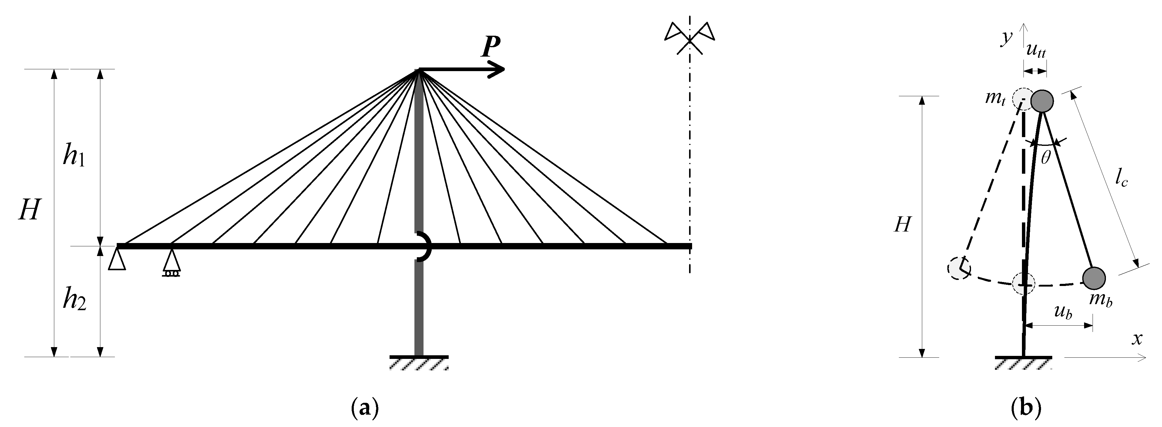
A reverse double-mass model is proposed at first based on the transfer paths of the horizontal seismic inertia forces of the main girder and bridge floor system of floating cable-stayed bridges under longitudinal seismic effects, as shown in Figure 1. The bottom of the tower is consolidated, and the main girder can be rotatable around the top of the tower. In Figure 1, and are concentrated mass at the top of the tower and center of gravity of the girder, respectively; , , and are the total height, lower tower column height, and upper tower column height, respectively; and denote the longitudinal displacement of the top of the tower and main girder, respectively; denotes the equivalent pendulum length of the cable, ; and denotes the swing angle of the main girder during floating longitudinal vibration. The equivalent swing rigidity of the main girder () can be obtained as [34]:
where , , and are the volume density, height, and bending moment of the inertia of the main girder, respectively.
Assuming that the free vibration of the above dual-degree freedom system is simple and harmonic and the elastic deformation of the cables and damping effects of the bridge are negligible, the frequency equation of the reverse double-mass model can be expressed as:
where is the structure rigidity matrix, expressed as ; is the structure mass matrix, expressed as ; and is the fundamental longitudinal frequency of the floating cable-stayed bridge. Further, the solution of Equation (2) is expressed as:
The longitudinal fundamental period of the floating cable-stayed bridge () can be obtained as:
2.2. The Longitudinal Hinged Cable-Stayed Bridge
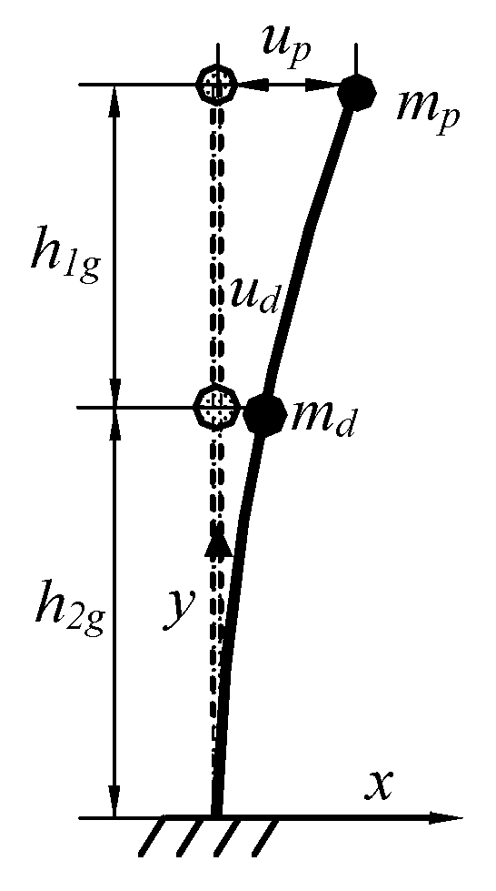
For a longitudinal hinged cable-stayed bridge, the equivalent mass is gathered at the center of the upper tower column, and the equivalent mass of girder, bridge deck system, and lower tower column is gathered at the beam tower connection of the bridge tower. So, the longitudinal hinged cable-stayed bridge can be simplified into a double-mass model, as shown in Figure 2, where and are longitudinal displacements of and , respectively, , and .
The horizontal deflection of and can be expressed by the flexibility influence coefficient of under the action of unit horizontal force, and the flexibility matrix can be given by:
where denotes the longitudinal bending stiffness of the main tower.
Taking the free vibration of the simplified structure with two degrees of freedom as simple harmonic vibration, and ignoring the damping effect of the structure, then the frequency equation of the simplified structure can be shown as follows:
where is the mass matrix of structures, expressed as , is the fundamental longitudinal vibration frequency of the cable-stayed bridge with a fixed hinge system, and is the unit matrix.
Substituting Equation (5) into Equation (6), the fundamental longitudinal frequency can be obtained as follows:
Therefore, the fundamental longitudinal period of the longitudinal hinged cable-stayed bridge can be expressed as follows:
3. Criterion of Low Gravity Center Cable-Stayed Bridge
3.1. Simplified Calculation of Tower Bottom Moment
It should be noted that for most loading types, the displacement contributions generally are greatest for the lower modes and tend to decrease for the higher modes. The contribution of the first-order longitudinal vibration mode of the floating cable-stayed bridge is more than 90%. In other words, once the first-order longitudinal vibration period is known, the seismic response of the tower bottom moment of the floating cable-stayed bridge may be calculated by the response spectrum method. The tower bottom moment can be expressed as follows:
where is the response spectrum acceleration corresponding to .
In the same way, for the longitudinal hinged cable-stayed bridge, without considering the contribution of mode shapes, the response of the bending moment at the tower bottom may be determined as follows:
where is the response spectrum acceleration corresponding to . The contribution of the first-order longitudinal vibration mode to the longitudinal seismic response for the longitudinal hinged cable-stayed bridge is about 30% [20], so it is necessary to modify the calculation result of Equation (9) as follows:
where is the modified tower bottom moment of the longitudinal hinged cable-stayed bridge, and is a coefficient of correction.
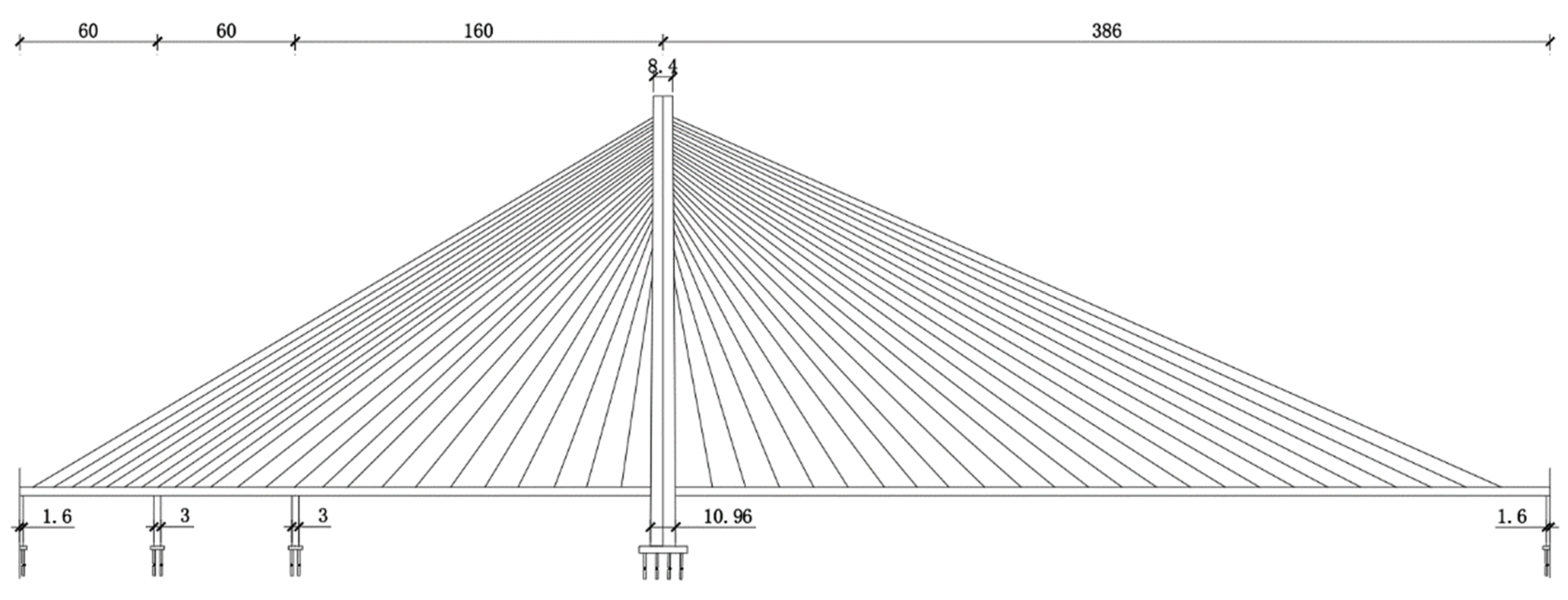
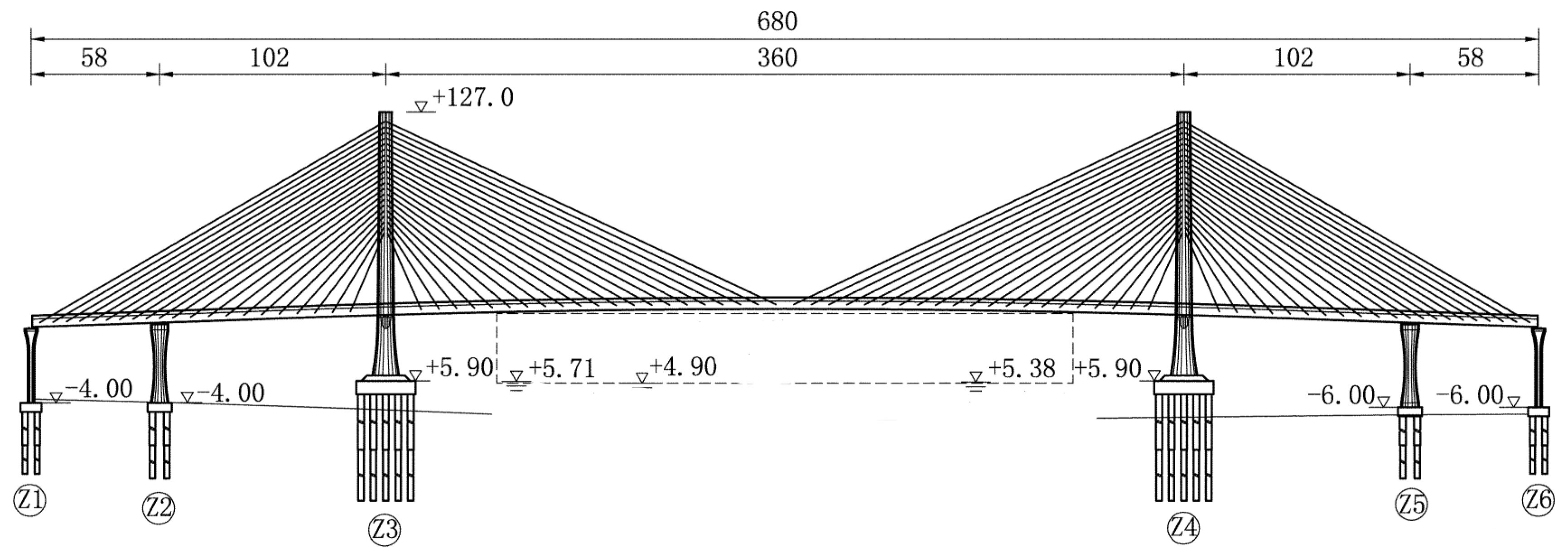
To define the value of the correction coefficient, the models with different heights of the gravity center are studied, which can be obtained by changing the lower tower height of Ji’nan No.3 bridge (single-tower cable-stayed bridge, as shown in Figure 3) and Qidu bridge (double-tower cable-stayed bridge, as shown in Figure 4), both of them are very representative in China’s cable-stayed bridges [35,36]. The ratio of the lower tower height to the total tower height was taken as a variable. The coefficients of correction for the bottom bending moment of the single-tower cable-stayed bridge and the double-tower cable-stayed bridge with the longitudinal hinged system under four different types of site standard response spectrum were studied, respectively. For , based on the parameters of the cable-stayed bridges in Table 1, the bottom bending moments of the longitudinal hinged cable-stayed bridges were obtained by Equation (10) and SAP2000, respectively. The comparisons are shown in Table 2. It could be seen that the ratio of the two was influenced by the earthquake wave type slightly, which can be ignored, but was greatly influenced by the bridge type. So, can be taken for a single-tower cable-stayed bridge and for a double-tower cable-stayed bridge.
3.2. Criterion of Low Gravity Center Cable-Stayed Bridge
The ratio of the bending moment at the tower bottom of the longitudinal floating cable-stayed bridge to the bending moment of the longitudinal hinged cable-stayed bridge can be defined as . Under the given seismic loading and site type, the cable-stayed bridge is called a low gravity center cable-stayed bridge if , for which the longitudinal hinged cable-stayed system is suitable. That is the criterion of a low gravity center cable-stayed bridge.
Further, by the simplified calculation formula of the tower bottom bending moment in Equations (9) and (11), the criterion formula of the low gravity center cable-stayed bridge can be expressed as follows:
For , the bridge is a low gravity center cable-stayed bridge, while for , the bridge is a conventional cable-stayed bridge.
3.3. Comparison with Numerical Results
Some examples are carried out to verify the accuracy of the simplified calculation formula of the bending moment of the tower bottom and the reliability of the criterion of a low gravity center cable-stayed bridge. The site type of the earthquake had less influence on the simplified calculation coefficient of correction of a longitudinal hinged cable-stayed bridge. Therefore, the response spectrum of site III was used to calculate the tower bottom bending moment and the criterion coefficient of low gravity center cable-stayed bridge for 10 cable-stayed bridges [26]. Equations (9) and (11) were used to calculate and , respectively, then the results were compared with that from finite element analysis. Furthermore, the results are shown in Table 2, in which , , and denote the results from finite element analysis. The following conclusions can be drawn.
- (1)
- For the 10 floating cable-stayed bridges, according to the comparison of the bottom bending moment calculated by Equation (9) and that from the finite element method (FEM) with the 10 floating cable-stayed bridges, the maximum relative error was −12.56%, the minimum relative error was only −0.83%, and the average relative error was 1.36%. This indicates that the simplified calculation formula of Equation (9) could very well predict the bottom bending moment of the floating cable-stayed bridge.
- (2)
- For the 10 longitudinal hinged cable-stayed bridges, the maximum relative error between the bottom bending moment calculated by Equation (11) and that of the FEM was 11.55%, the minimum relative error was only −2.17%, and the average relative error was 4.65%. This showed that the simplified calculation formula of the bottom bending moment of the longitudinal hinged cable-stayed bridge was reasonable.
- (3)
- The standard deviations of relative error of the bending moment calculated by the simplified formulae and FEM of the floating cable-stayed bridge and the longitudinal hinged cable-stayed bridge were 9.2% and 4.5%, respectively, which showed that the simplified formulae had good stability.
- (4)
- The conclusion given by the criterion formula of Equation (12) of a low gravity center cable-stayed bridge was in good agreement with that from the FEM, which showed that the criterion formula of a low gravity center cable-stayed bridge was reliable and was helpful for the reasonable structural system selection in the preliminary design of the cable-stayed bridge.
4. Conclusions
To make the scheme comparison and preliminary design of the cable-stayed bridge, we put forward the simplified criterion formula for a low gravity center cable-stayed bridge. The conclusions are the following:
- (1)
- Based on the simplified formula of the longitudinal fundamental period of cable-stayed bridges and combined with the response spectrum analysis method, the criterion formula of a low gravity center cable-stayed bridge was developed.
- (2)
- The conclusion given by the criterion formula of a low gravity center cable-stayed bridge was in good agreement with that from the FEM and tests, which revealed that the criterion formula of a low gravity center cable-stayed bridge is reasonable and can provide references for the preliminary design and the scheme selection of the cable-stayed bridge.
- (3)
- The seismic response characteristics of cable-stayed bridges are related to the structural system and the seismic characteristics. Therefore, whether a cable-stayed bridge is a low center of gravity cable-stayed bridge is also related to the structural characteristics of the cable-stayed bridge itself and the ground motion characteristics of its site.
Author Contributions
Conceptualization, Y.C. and W.Z.; methodology, Y.C. and Y.W.; software, Y.W.; validation, W.Z. and Y.C.; formal analysis, K.L.; investigation, Y.W.; data curation, K.L.; writing—original draft preparation, Y.C.; writing—review and editing, Y.W. and X.D. All authors have read and agreed to the published version of the manuscript.
Funding
This research was funded by the National Natural Science Foundation of China, Grant No. 51778022, and Natural Science Foundation of Beijing Municipality, Grant No. 8172008.
Institutional Review Board Statement
Not applicable.
Informed Consent Statement
Not applicable.
Data Availability Statement
All data generated or analyzed during this study are included in this article.
Conflicts of Interest
The authors declare no conflict of interest.
References
- Wang, F.; Zhou, Q.-X. Structural behaviors of cable-stayed bridge with high piers. In Proceedings of the International Conference on Energy Development and Environmental Protection (EDEP 2017), Guilin, China, 18–20 August 2017. [Google Scholar]
- Camara, A.; Astiz, M.A. Analysis and control of cable-stayed bridges subject to seismic action. Struct. Eng. Int. 2014, 24, 27–36. [Google Scholar] [CrossRef]
- Su, X.; Kang, H.; Guo, T.; Cong, Y. Modeling and parametric analysis of in-plane free vibration of a floating cable-stayed bridge with transfer matrix method. Int. J. Struct. Stab. Dyn. 2019, 20, 2050004. [Google Scholar] [CrossRef]
- Kim, T.; Kwon, O.-S.; Song, J. Seismic performance of a long-span cable-stayed bridge under spatially varying bidirectional spectrum-compatible ground motions. J. Struct. Eng. 2021, 147, 04021015. [Google Scholar] [CrossRef]
- Li, X.; Fu, P.; Xu, L.; Xin, L. Assessing time-dependent damage to a cable-stayed bridge through multi-directional ground motions based on material strain measures. Eng. Struct. 2021, 227, 111417. [Google Scholar] [CrossRef]
- Zhang, C.; Lu, J.-B.; Jia, H.-Y.; Lai, Z.-C.; Li, X.; Wang, P.-G. Influence of near-fault ground motion characteristics on the seismic response of cable-stayed bridges. Bull. Earthq. Eng. 2020, 18, 6375–6403. [Google Scholar] [CrossRef]
- Zhang, C.; Lu, J.; Zhou, Z.; Yan, X.; Xu, L.; Lin, J. Lateral seismic fragility assessment of cable-stayed bridge with diamond-shaped concrete pylons. Shock Vib. 2021, 2021, 1–14. [Google Scholar] [CrossRef]
- Zhang, C.; Wen, J.; Han, Q.; Du, X.; Lai, Z.; Fu, G. Transverse seismic response of diamond-shaped pylon in cable-stayed bridge: Experiment and analysis. Eng. Struct. 2022, 250, 113414. [Google Scholar] [CrossRef]
- Nazmy, A.S.; Abdel-Ghaffar, A.M. Non-linear earthquake-response analysis of long-span cable-stayed bridges: Applications. Earthq. Eng. Struct. Dyn. 1990, 19, 63–76. [Google Scholar] [CrossRef]
- Ren, W.-X.; Peng, X.-L.; Lin, Y.-Q. Experimental and analytical studies on dynamic characteristics of a large span cable-stayed bridge. Eng. Struct. 2005, 27, 535–548. [Google Scholar] [CrossRef]
- Soneji, B.B.; Jangid, R.S. Passive hybrid systems for earthquake protection of cable-stayed bridge. Eng. Struct. 2007, 29, 57–70. [Google Scholar] [CrossRef]
- Zhang, W.X.; Li, J.Z.; Li, H.F. Study of seismic response characteristics of low gravity center cable-stayed bridge. Bridge Constr. 2007, 5, 21–23. (In Chinese) [Google Scholar]
- Guo, W.; Li, J.; Guan, Z. Shake table test on a long-span cable-stayed bridge with viscous dampers considering wave passage effects. J. Bridge Eng. 2021, 26, 04020118. [Google Scholar] [CrossRef]
- Liang, X.; Li, B.; Liu, X.; Liang, L. Optimisation of longitudinal seismic energy dissipation system for straddle-type monorail-cum-road long-span cable-stayed bridge. Shock Vib. 2019, 2019, 1–16. [Google Scholar] [CrossRef]
- Xu, Y.; Tong, C.; Li, J. Simplified calculation method for supplemental viscous dampers of cable-stayed bridges under near-fault ground motions. J. Earthq. Eng. 2018, 25, 65–81. [Google Scholar] [CrossRef]
- Zhang, W.X.; Li, C.H.; Yang, J.B. Earthquake Resistance of Cable-stayed Bridge with One Tower of Low Gravity Center. J. Shijiazhuang Tiedao Univ. Nat. Sci. Ed. 2010, 23, 88–93. (In Chinese) [Google Scholar]
- Zhang, W.; Lu, P.; Wu, H.; Li, Q. Study on the damping reduction of the safe-belt constraint system of low Gravity Center cable-stayed bridge. Vibroeng. Procedia 2017, 14, 184–191. [Google Scholar] [CrossRef] [Green Version]
- Camara, A.; Efthymiou, E. Deck–tower interaction in the transverse seismic response of cable-stayed bridges and optimum configurations. Eng. Struct. 2016, 124, 494–506. [Google Scholar] [CrossRef] [Green Version]
- Wang, Z.; Zhang, W.; Fang, R.; Zhao, H. Dynamic model testing of low-gravity-center cable-stayed bridges with different girder-to-tower connections. J. Bridge Eng. 2021, 26, 04020112. [Google Scholar] [CrossRef]
- Xie, W.; Sun, L.; Lou, M. Wave-passage effects on seismic responses of pile–soil–cable-stayed bridge model under longitudinal non-uniform excitation: Shaking table tests and numerical simulations. Bull. Earthq. Eng. 2020, 18, 5221–5246. [Google Scholar] [CrossRef]
- Zhou, L.; Wang, X.; Ye, A. Shake table test on transverse steel damper seismic system for long span cable-stayed bridges. Eng. Struct. 2019, 179, 106–119. [Google Scholar] [CrossRef]
- Sun, L.; Xie, W. Evaluation of pile-soil-structure interaction effects on the seismic responses of a super long-span cable-stayed bridge in the transverse direction: A shaking table investigation. Soil Dyn. Earthq. Eng. 2019, 125, 105755. [Google Scholar] [CrossRef]
- Luo, X.; Li, X.; Fu, X.; Gu, L. Research on bridge structural health assessment based on Finite Element Analysis. Tehnički Vjesnik 2020, 27, 96–105. [Google Scholar]
- Dong, F.-H. Virtual reality research on vibration characteristics of long-span bridges with considering vehicle and wind loads based on neural networks and finite element method. Neural Comput. Appl. 2017, 29, 1303–1309. [Google Scholar] [CrossRef]
- Zhang, W.; Chen, Y.; Kou, W.; Du, X. Simplified calculation method for the fundamental period of floating cable-stayed bridge. Arch. Appl. Mech. 2017, 88, 329–339. [Google Scholar] [CrossRef]
- Zhang, W.; Chen, Y.; Huang, J.; Li, Y. Simplified calculation method for transverse seismic response of aqueducts considering fluid-structure interaction. J. Vibroeng. 2017, 19, 6135–6151. [Google Scholar] [CrossRef] [Green Version]
- Clough, R.W.; Penzien, J. Dynamics of Structures; McGraw-Hill: New York, NY, USA, 1991. [Google Scholar]
- China Construction Industry Press. Code for Design of the Municipal Bridge; Ministry of Housing and Urban-Rural Development of the People’s Republic of China: Beijing, China, 2011. [Google Scholar]
- China Merchants Chongqing Transportation Scientific Research Institute Co., Ltd. Specifications for Seismic Design of Highway Bridge; Ministry of Transport of the People’s Republic of China: Beijing, China, 2020. [Google Scholar]
- Yuan, W.; Yan, D. Simplified calculation method for longitudinal drift frequency of cable-stayed bridge. J. Tongji Univ. Nat. Sci. Ed. 2005, 11, 5–9. (In Chinese) [Google Scholar]
- Liu, C. The Design Analyses of the Displacement Constraint and the Seismic Mitigation for Elastic-Plastic Seismic Isolator of Railway Bridges. Ph.D. Thesis, Beijing Jiaotong University, Beijing, China, 2019. (In Chinese). [Google Scholar]
- Yang, H.; Li, J. Simplified calculation of the concept of longitudinal drift frequency of cable-stayed bridges and discussion of influencing factors. Build. Struct. 2015, 45, 93–96. (In Chinese) [Google Scholar]
- Zhang, W.; Kou, W.; Chen, Y.; Wang, Z. Calculation of first-order natural vibration period of longitudinal first-order cable-stayed bridge based on double-particle model. Bridge Constr. 2016, 46, 98–102. (In Chinese) [Google Scholar]
- Zhang, W.; Liang, K.; Chen, Y. Relationship between the vibration acceleration and stability of a continuous girder bridge during horizontal rotation. Sustainability 2022, 14, 5853. [Google Scholar] [CrossRef]
- Su, Q.; Zhai, H.; Wu, C. Model Test Study of Horizontal Load-Bearing Behavior of Anchorage Zone in Cable Pylon of the 3rd Ji’ nan Huanghe River Bridge. Bridge Constr. 2008, 3, 12–14. (In Chinese) [Google Scholar]
- Li, L.; Li, L.; Wang, X. Design of Main Bridge of North Bridge of Qidu Bridge. Bridge Constr. 2016, 46, 4. (In Chinese) [Google Scholar]
Figure 1.
Simplified calculation model schematic diagram. (a) Transfer paths of the horizontal seismic inertia forces; (b) The reverse double-mass model.
Figure 1.
Simplified calculation model schematic diagram. (a) Transfer paths of the horizontal seismic inertia forces; (b) The reverse double-mass model.

Figure 2.
The double-mass simplified model.

Figure 3.
The overall layout diagram of Ji’nan No.3 bridge (m).

Figure 4.
The overall layout diagram of Qidu bridge (m).


Table 1.
Comparison of the bending moments.
| Site Type | Single-Tower Cable-Stayed Bridge (Ji’nan No.3 Bridge) | Dual-Tower Cable-Stayed Bridge (Qidu Bridge) | |||||
|---|---|---|---|---|---|---|---|
| I | 1/10 | 8.86 | 9.80 | 1.23 | 5.45 | 6.34 | 1.19 |
| 2/10 | 9.04 | 10.1 | 1.37 | 8.28 | 8.65 | 1.09 | |
| 3/10 | 11.52 | 12.93 | 1.47 | 13.66 | 13.29 | 1.06 | |
| 4/10 | 13.35 | 14.28 | 1.49 | 19.33 | 18.57 | 1.01 | |
| 5/10 | 15.65 | 17.33 | 1.52 | 26.42 | 25.02 | 1.05 | |
| II | 1/10 | 13.12 | 14.52 | 1.25 | 8.07 | 9.26 | 1.18 |
| 2/10 | 13.39 | 14.97 | 1.37 | 12.27 | 12.74 | 1.09 | |
| 3/10 | 17.06 | 19.15 | 1.47 | 20.24 | 19.7 | 1.06 | |
| 4/10 | 19.78 | 21.16 | 1.49 | 28.64 | 27.52 | 1.06 | |
| 5/10 | 23.18 | 25.67 | 1.52 | 39.14 | 37.07 | 1.09 | |
| III | 1/10 | 18.04 | 19.96 | 1.23 | 11.09 | 12.76 | 1.18 |
| 2/10 | 18.41 | 20.58 | 1.39 | 16.87 | 17.39 | 1.09 | |
| 3/10 | 23.46 | 26.34 | 1.47 | 27.84 | 27.1 | 1.06 | |
| 4/10 | 27.2 | 29.10 | 1.49 | 39.38 | 37.86 | 1.10 | |
| 5/10 | 31.87 | 35.30 | 1.52 | 53.81 | 50.96 | 1.11 | |
| IV | 1/10 | 22.14 | 24.50 | 1.25 | 13.62 | 15.57 | 1.18 |
| 2/10 | 22.6 | 25.27 | 1.39 | 8.28 | 8.65 | 1.08 | |
| 3/10 | 28.79 | 32.35 | 1.47 | 34.16 | 33.24 | 1.05 | |
| 4/10 | 33.38 | 35.72 | 1.49 | 48.33 | 46.48 | 1.11 | |
| 5/10 | 39.11 | 43.32 | 1.52 | 66.04 | 62.56 | 1.12 | |
| average | - | - | 1.42 | - | - | 1.10 | |
Table 2.
Comparison of simplified formulae and FEM.
| Bridge | The Floating Cable-Stayed Bridge | The Longitudinal Hinged Cable-Stayed Bridge | Criterion | |||||
|---|---|---|---|---|---|---|---|---|
| Jinan No.3 | 18.41 | 20.58 | 10.55 | 16.87 | 17.39 | 3.03 | 0.92 | 0.84 |
| Songhuajiang | 15.36 | 14.31 | −7.33 | 10.49 | 10.27 | −2.17 | 0.68 | 0.72 |
| Songyuan | 14.58 | 13.20 | −10.45 | 24.14 | 26.43 | 8.66 | 1.66 | 2.00 |
| Nanye Road | 12.88 | 12.23 | −5.30 | 16.59 | 16.06 | −3.29 | 1.29 | 1.31 |
| Haihe | 16.01 | 17.08 | 6.26 | 18.73 | 19.81 | 5.44 | 1.17 | 1.16 |
| Feiyunjiang | 7.51 | 8.44 | 11.02 | 9.53 | 10.03 | 4.99 | 1.27 | 1.19 |
| Jintang | 15.07 | 13.39 | −12.56 | 20.43 | 22.56 | 9.47 | 1.36 | 1.68 |
| Qidu | 8.02 | 9.01 | 10.98 | 10.47 | 10.74 | 2.51 | 1.31 | 1.19 |
| Taizhouwan | 10.06 | 9.98 | −0.83 | 10.18 | 10.86 | 6.28 | 1.01 | 1.09 |
| Sutong | 48.15 | 54.25 | 11.24 | 48.51 | 54.85 | 11.55 | 1.01 | 1.01 |
| Standard Deviation | / | / | 9.2% | / | / | 4.5% | / | / |
Publisher’s Note: MDPI stays neutral with regard to jurisdictional claims in published maps and institutional affiliations. |
© 2022 by the authors. Licensee MDPI, Basel, Switzerland. This article is an open access article distributed under the terms and conditions of the Creative Commons Attribution (CC BY) license (https://creativecommons.org/licenses/by/4.0/).
Share and Cite
MDPI and ACS Style
Chen, Y.; Wang, Y.; Zhang, W.; Liang, K.; Du, X. Simplified Criterion for Low Gravity Center Cable-Stayed Bridge Based on Response Spectrum Analyses. Sustainability 2022, 14, 10570. https://doi.org/10.3390/su141710570
AMA Style
Chen Y, Wang Y, Zhang W, Liang K, Du X. Simplified Criterion for Low Gravity Center Cable-Stayed Bridge Based on Response Spectrum Analyses. Sustainability. 2022; 14(17):10570. https://doi.org/10.3390/su141710570
Chicago/Turabian StyleChen, Ying, Yonghuan Wang, Wenxue Zhang, Kun Liang, and Xiuli Du. 2022. "Simplified Criterion for Low Gravity Center Cable-Stayed Bridge Based on Response Spectrum Analyses" Sustainability 14, no. 17: 10570. https://doi.org/10.3390/su141710570
Note that from the first issue of 2016, this journal uses article numbers instead of page numbers. See further details here.