
Design and Optimization of Fractional Order PID Controller to Enhance Energy Storage System Contribution for Damping Low-Frequency Oscillation in Power Systems Integrated with High Penetration of Renewable Sources


Abstract
:1. Introduction
- (1)
- lack of transmission line system,
- (2)
- disparity between loads and generation units, and
- (3)
- fluctuations in the load [6]. This paper considers two types of LFO: local area and inter-area oscillations. The inter-area oscillation mode was distinguished in the inefficient transmission systems linked to large generation units [6]. The inter-area oscillations occur between [0.1–0.7] Hz. In contrast, the local area oscillation was notable in one of the generators in the power systems. The local area oscillation is between (0.7–2.0] Hz [5,6,7,8].
- (1)
- the integration between the multimachine power system and high penetration of RES is considered,
- (2)
- adding SMES to the power system integrated with high penetration of RES such as wind turbine and PV solar system, and
- (3)
- proposed a PSO to tune a PID and FOPID controllers to enhance the SMES contribution for damping LFO.
2. Power System Modeling
2.1. Synchronous Generator
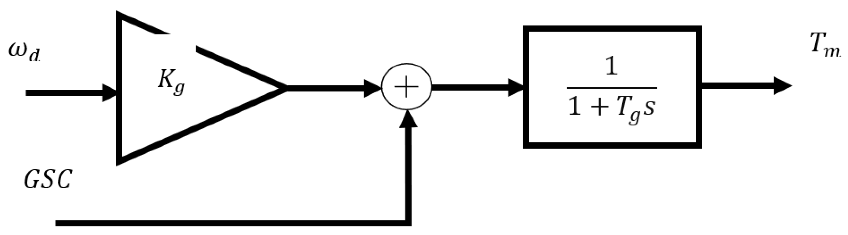
2.2. Governor System
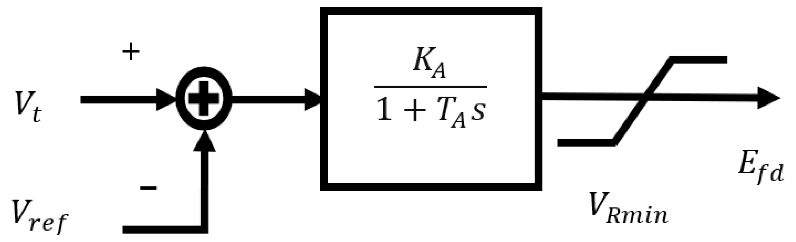
2.3. Excitation System
3. RES Modeling
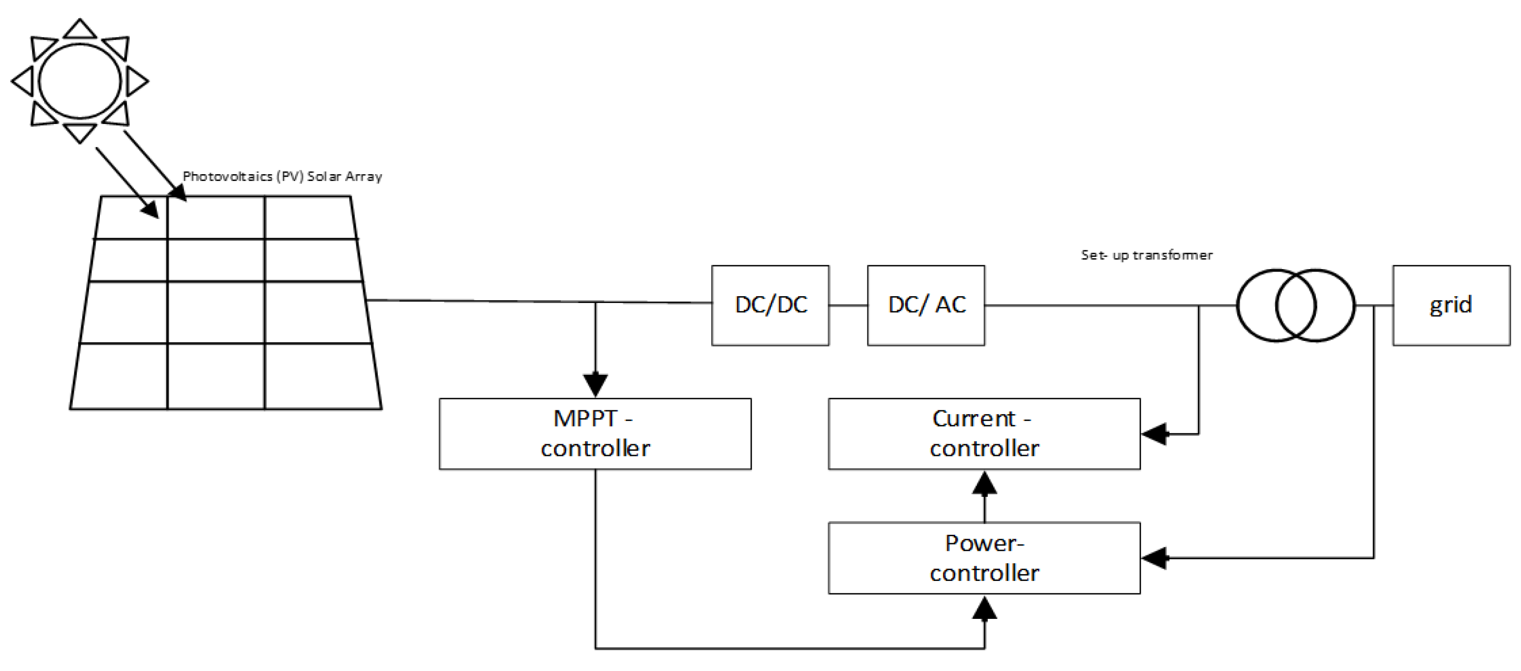
3.1. PV
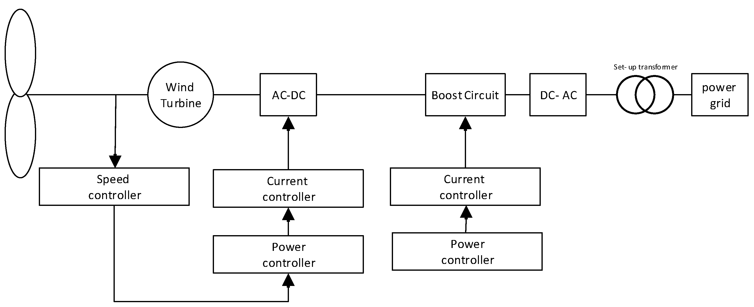
3.2. Wind Turbine
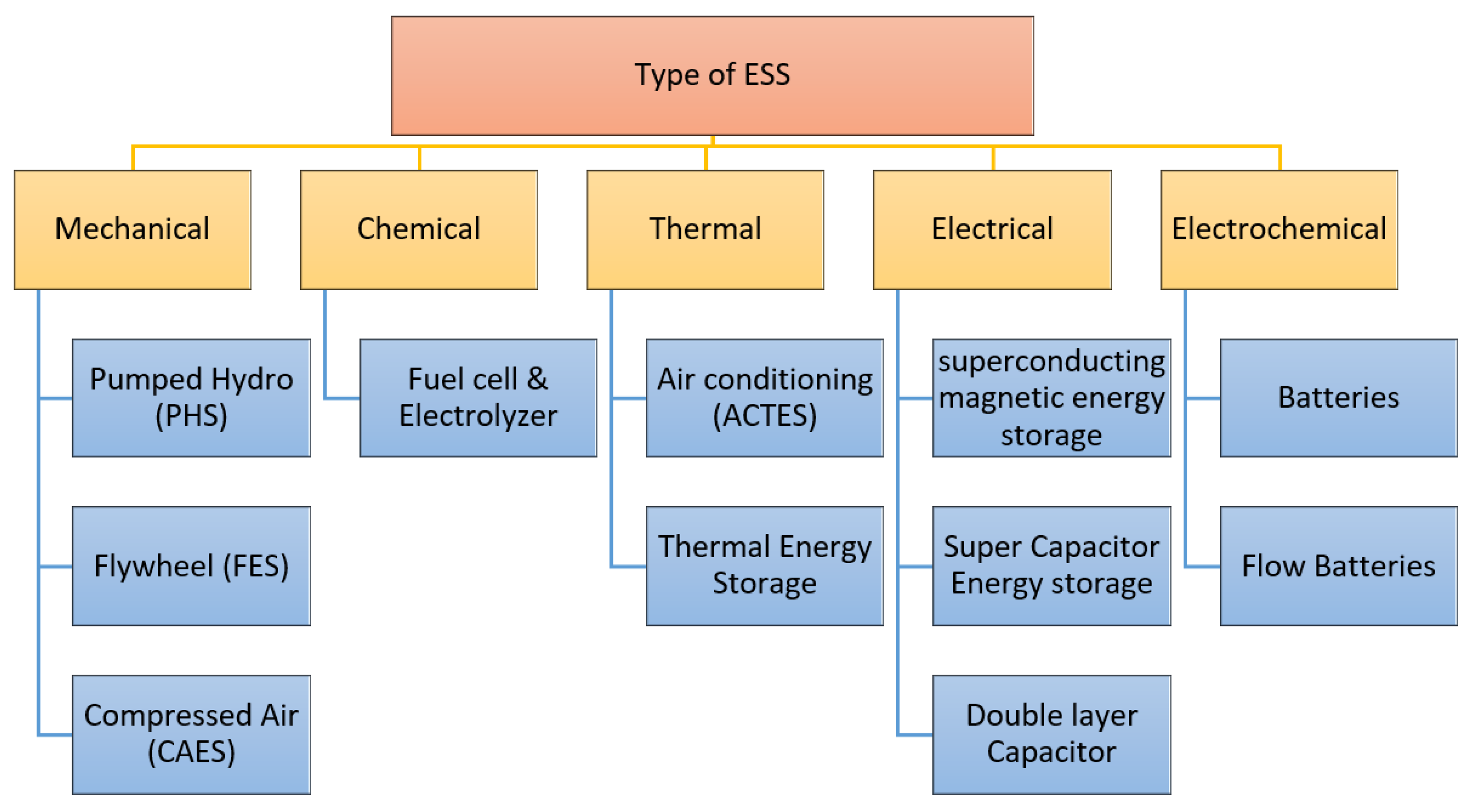
4. ESSs
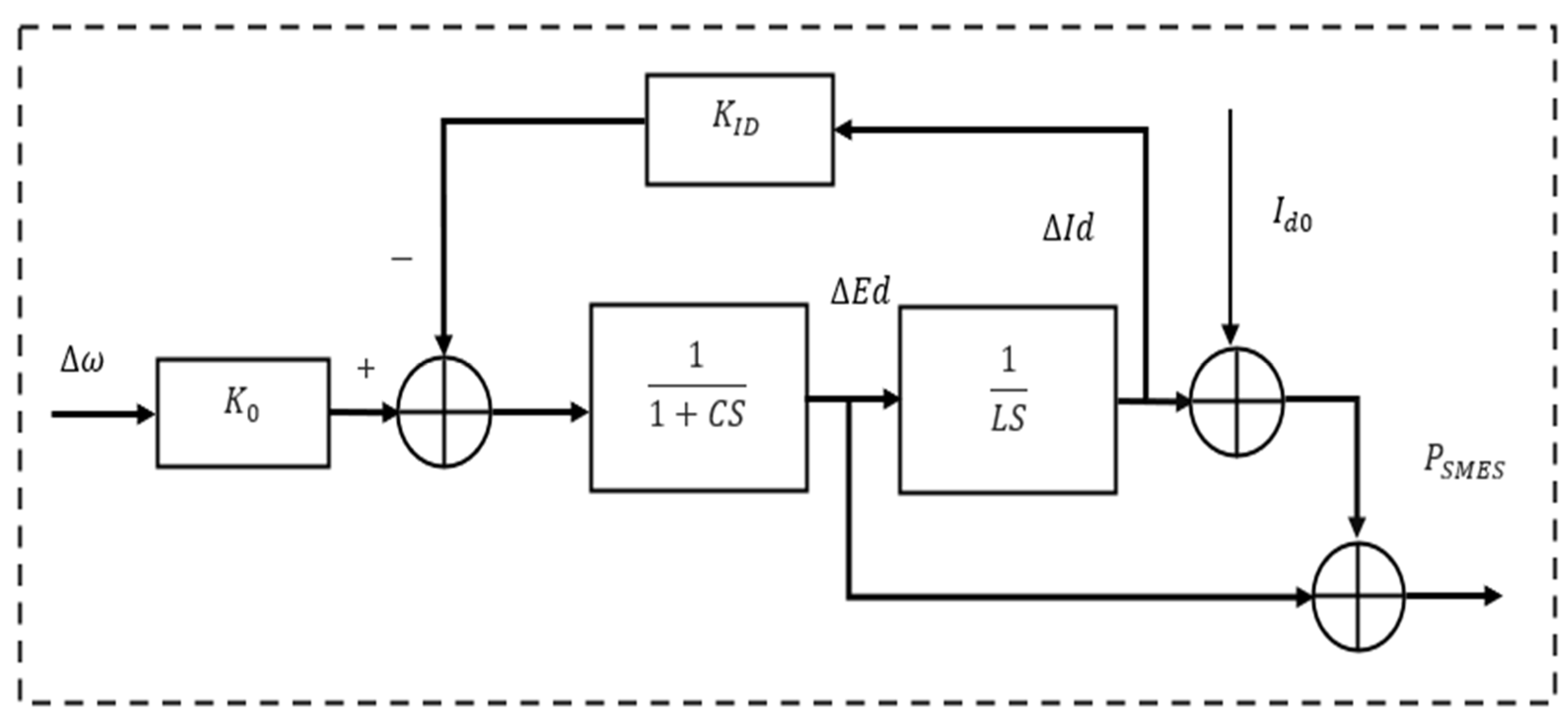
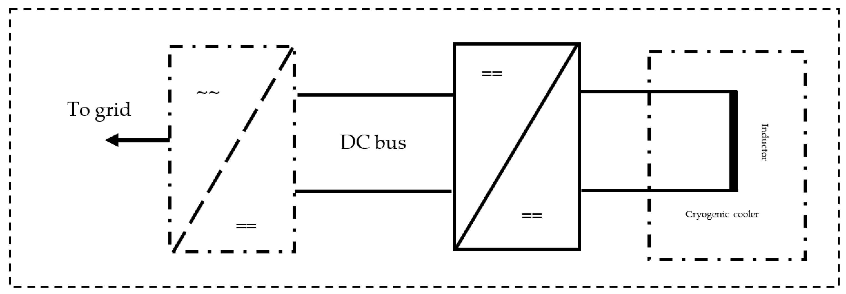
SMES
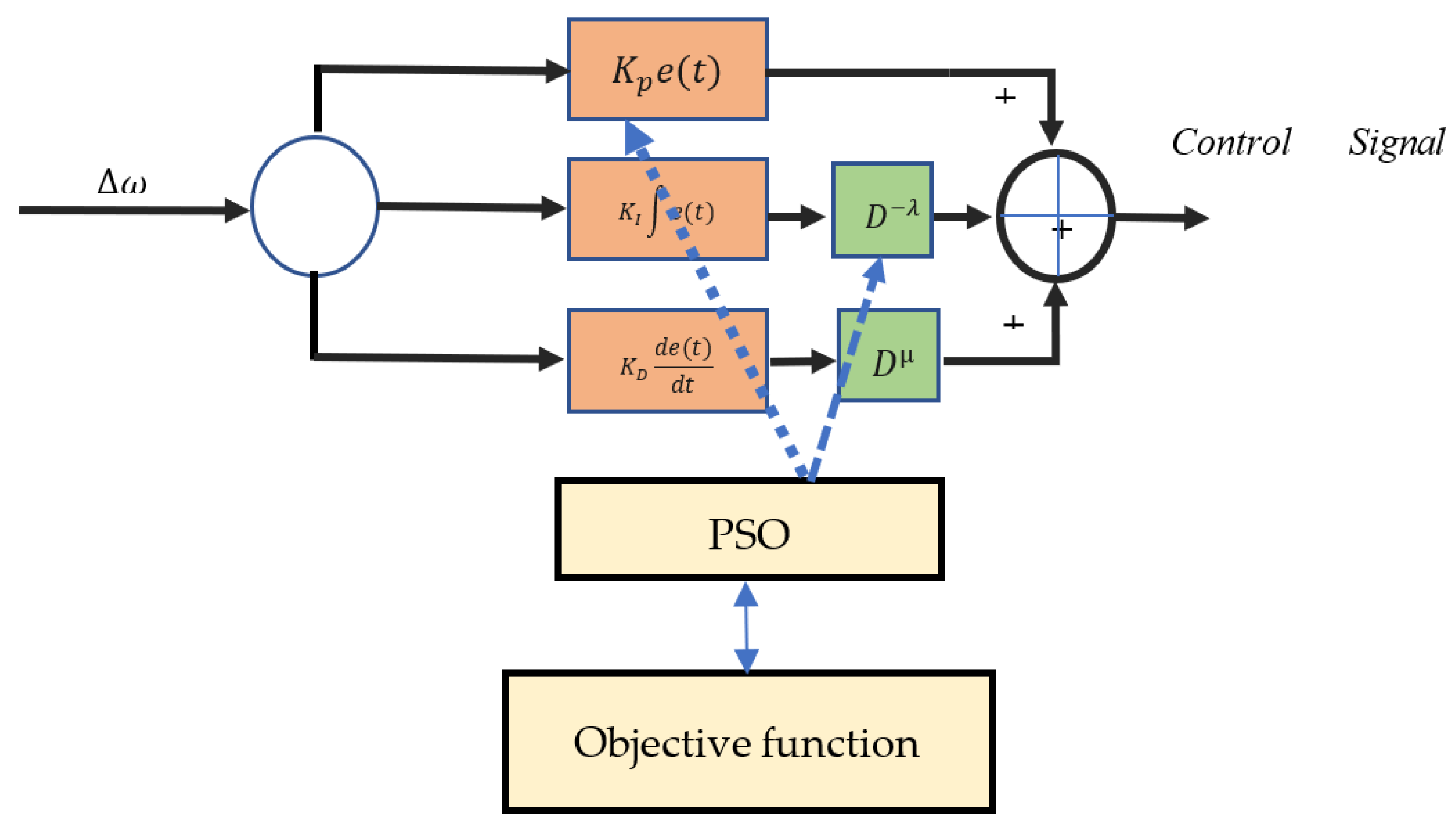
5. PID and FOPID
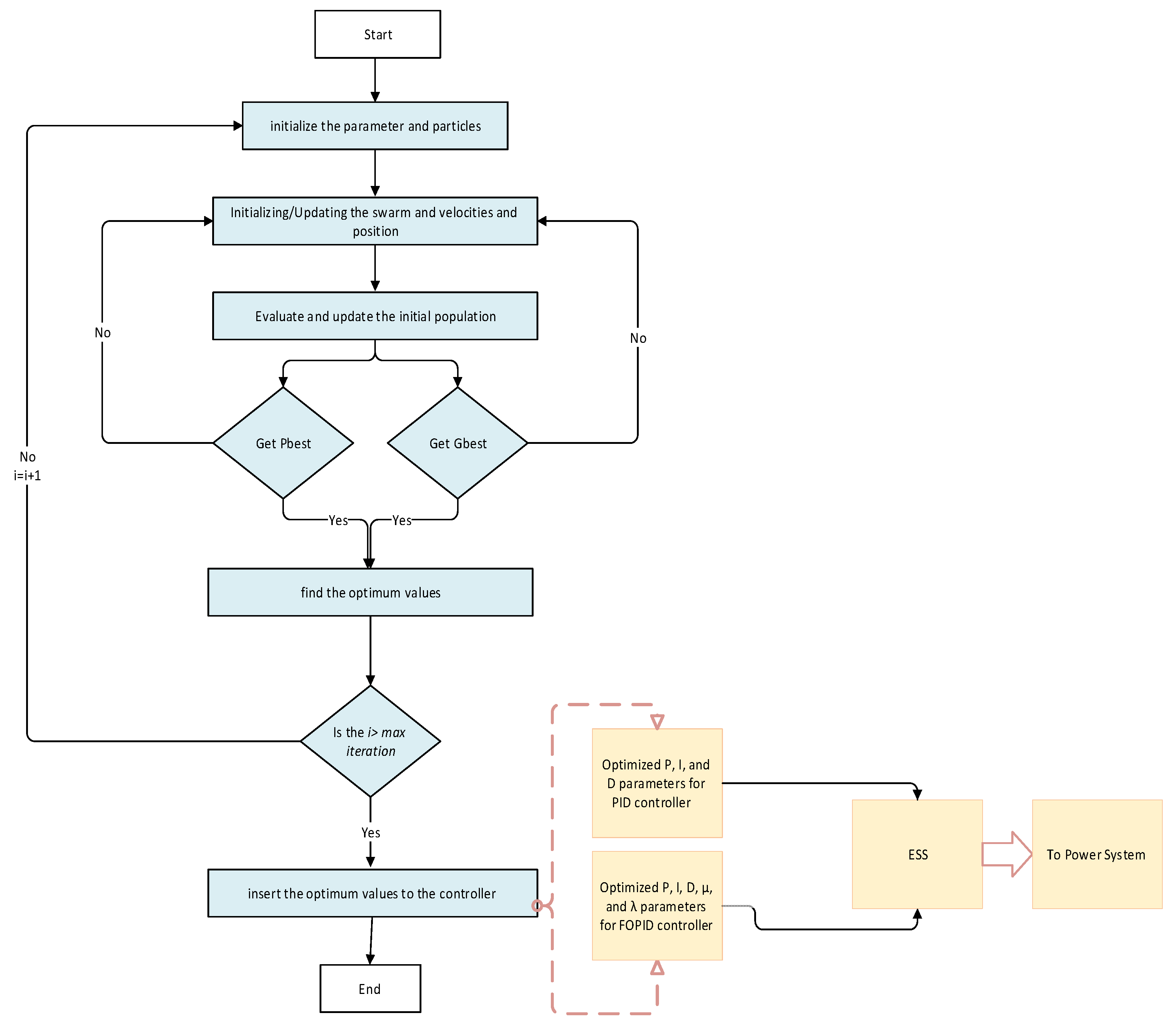
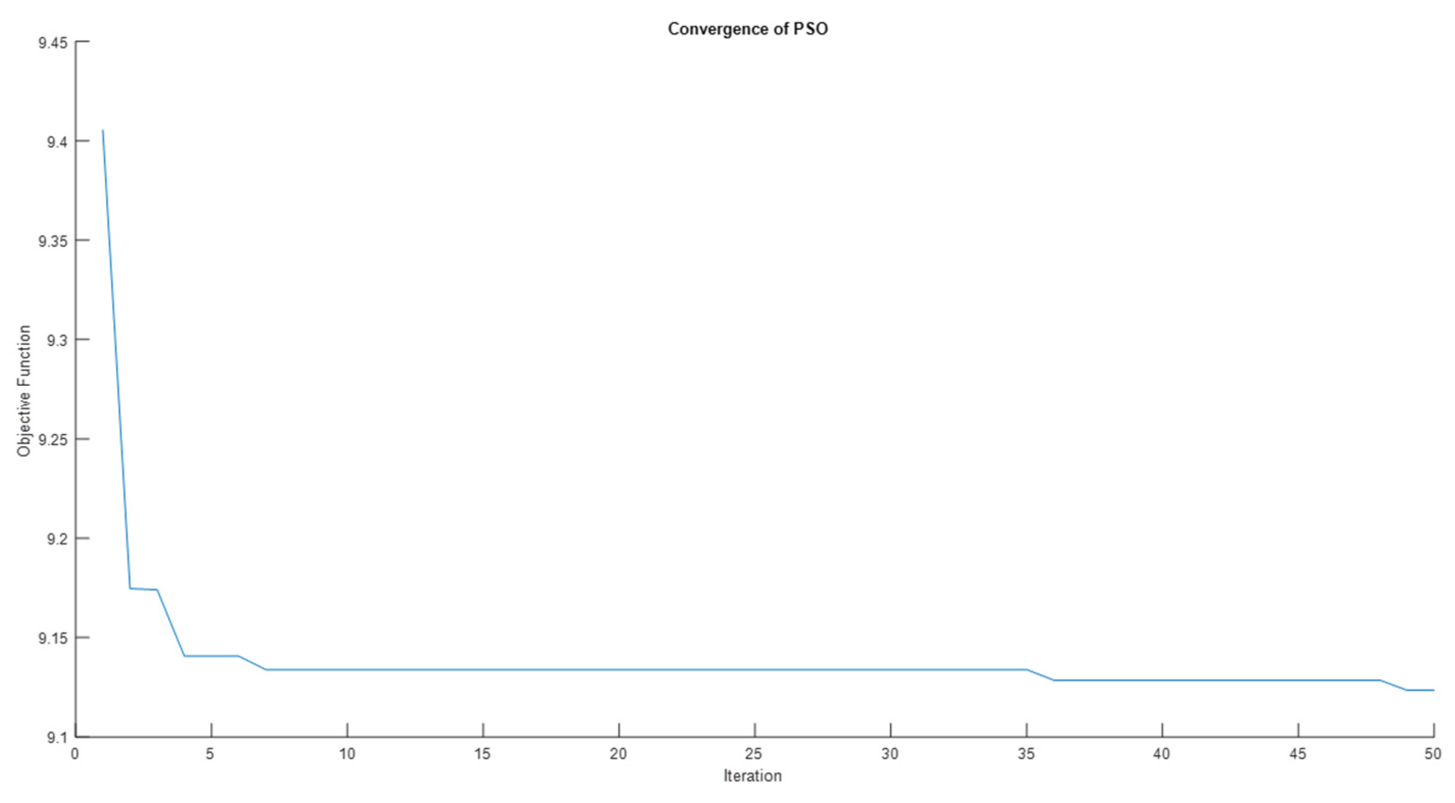
6. PSO
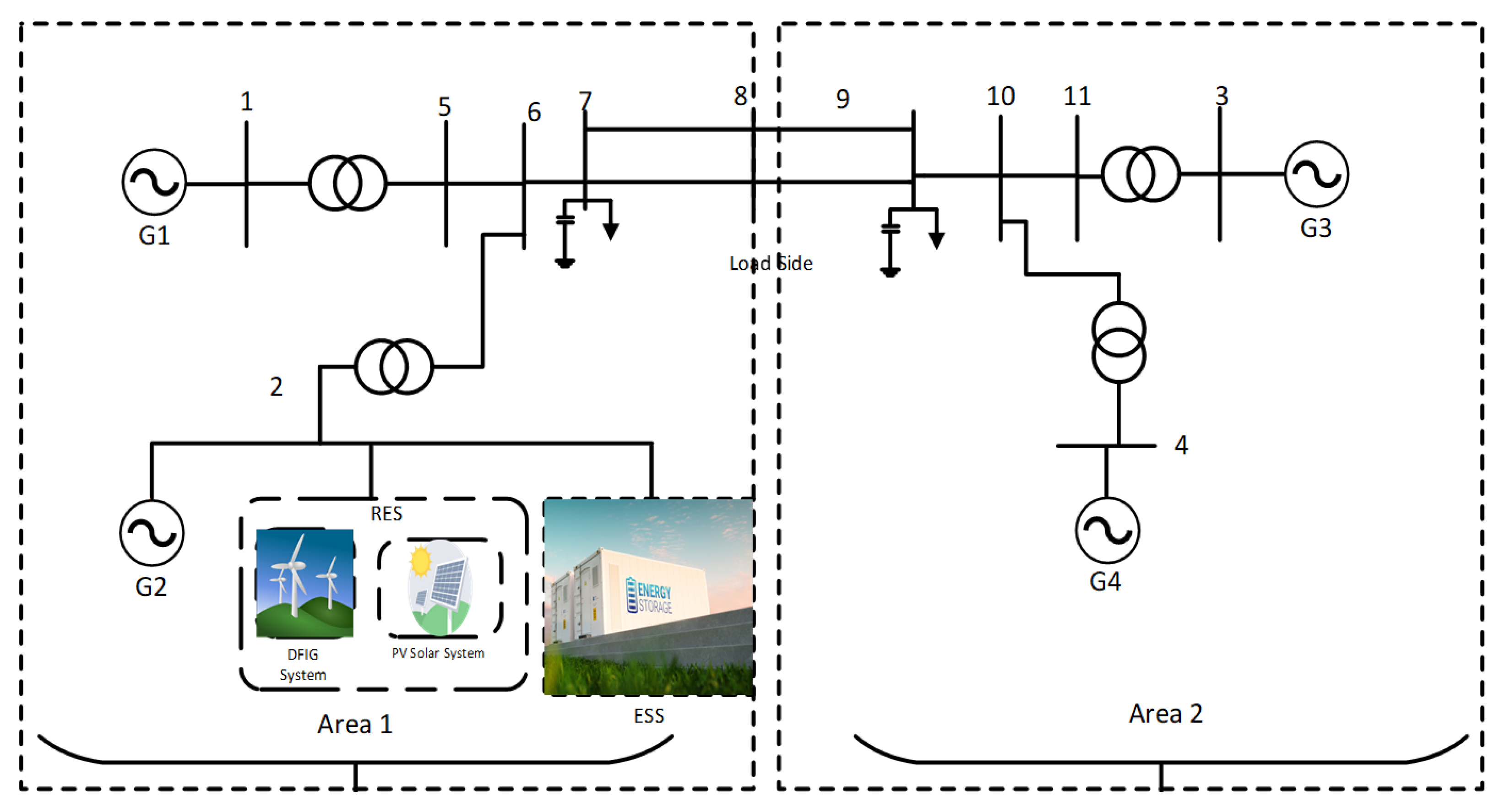
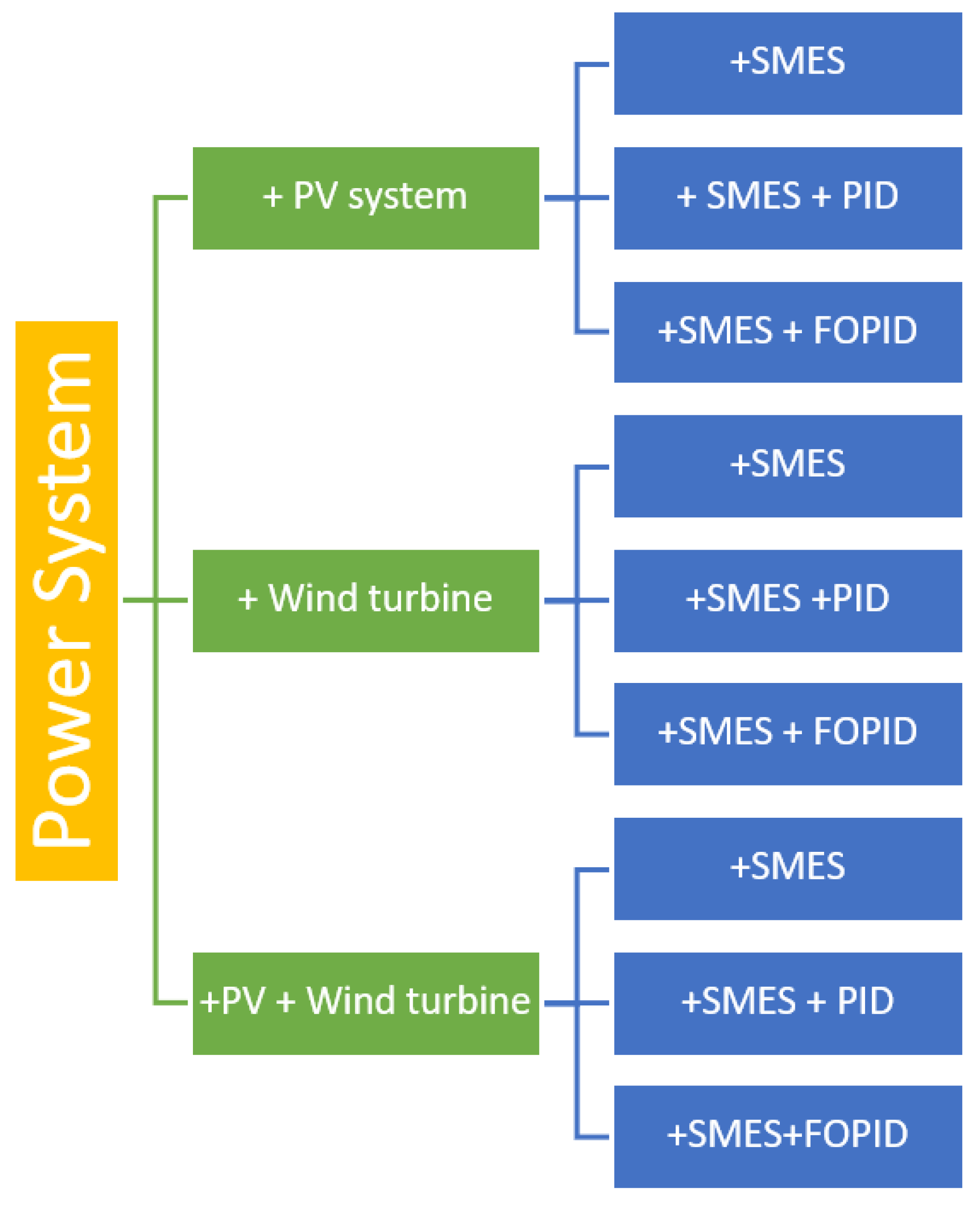
7. Case Study
8. Simulation Results
8.1. Time-Domain Simulation Results
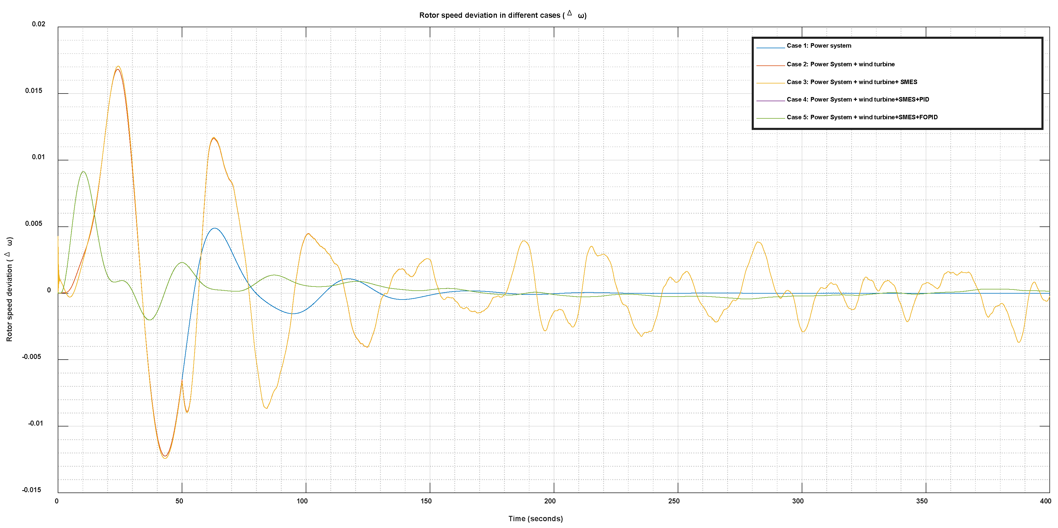
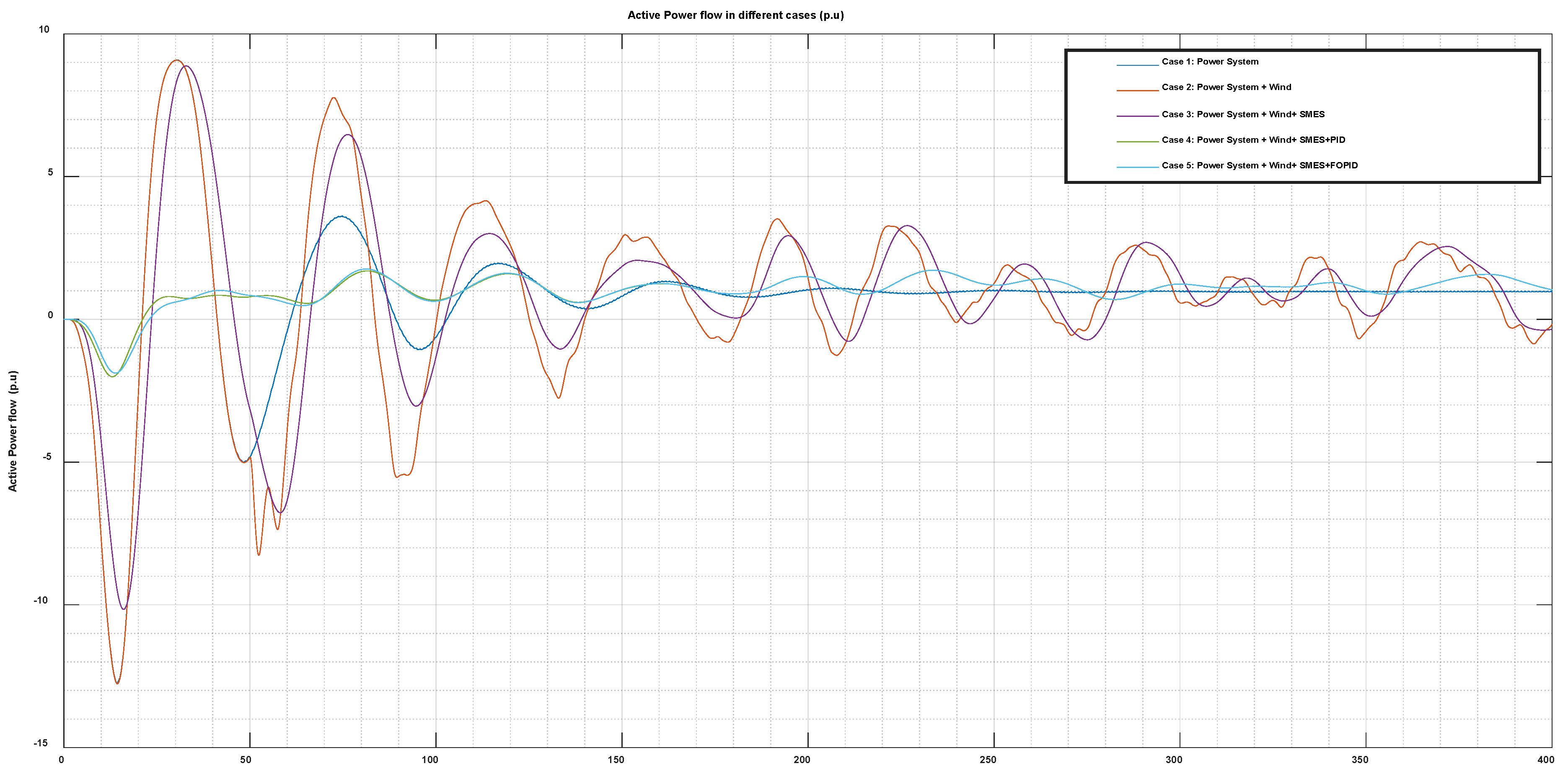
8.1.1. Power System with Wind Turbine Scenario
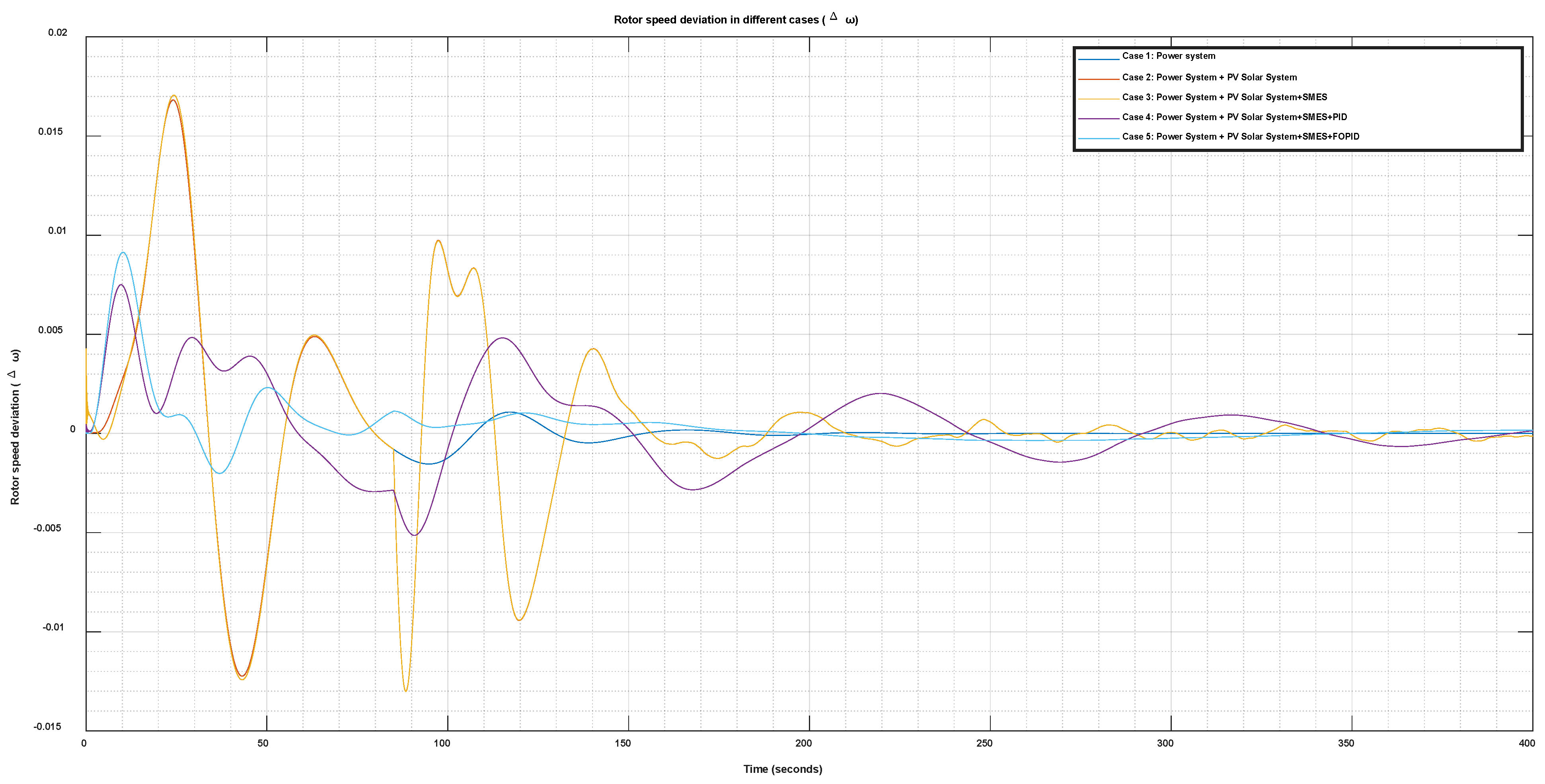
8.1.2. Power System with PV Scenario
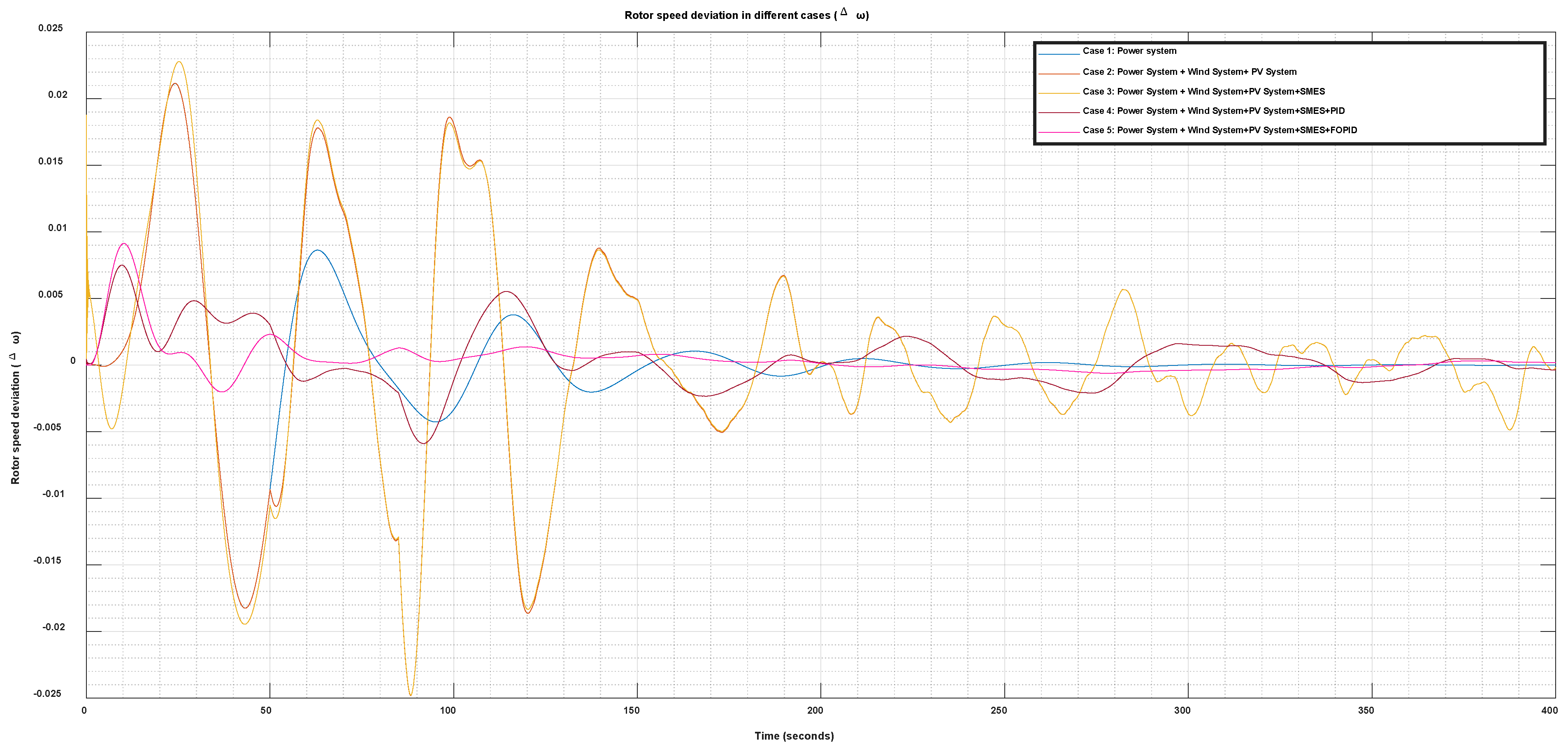
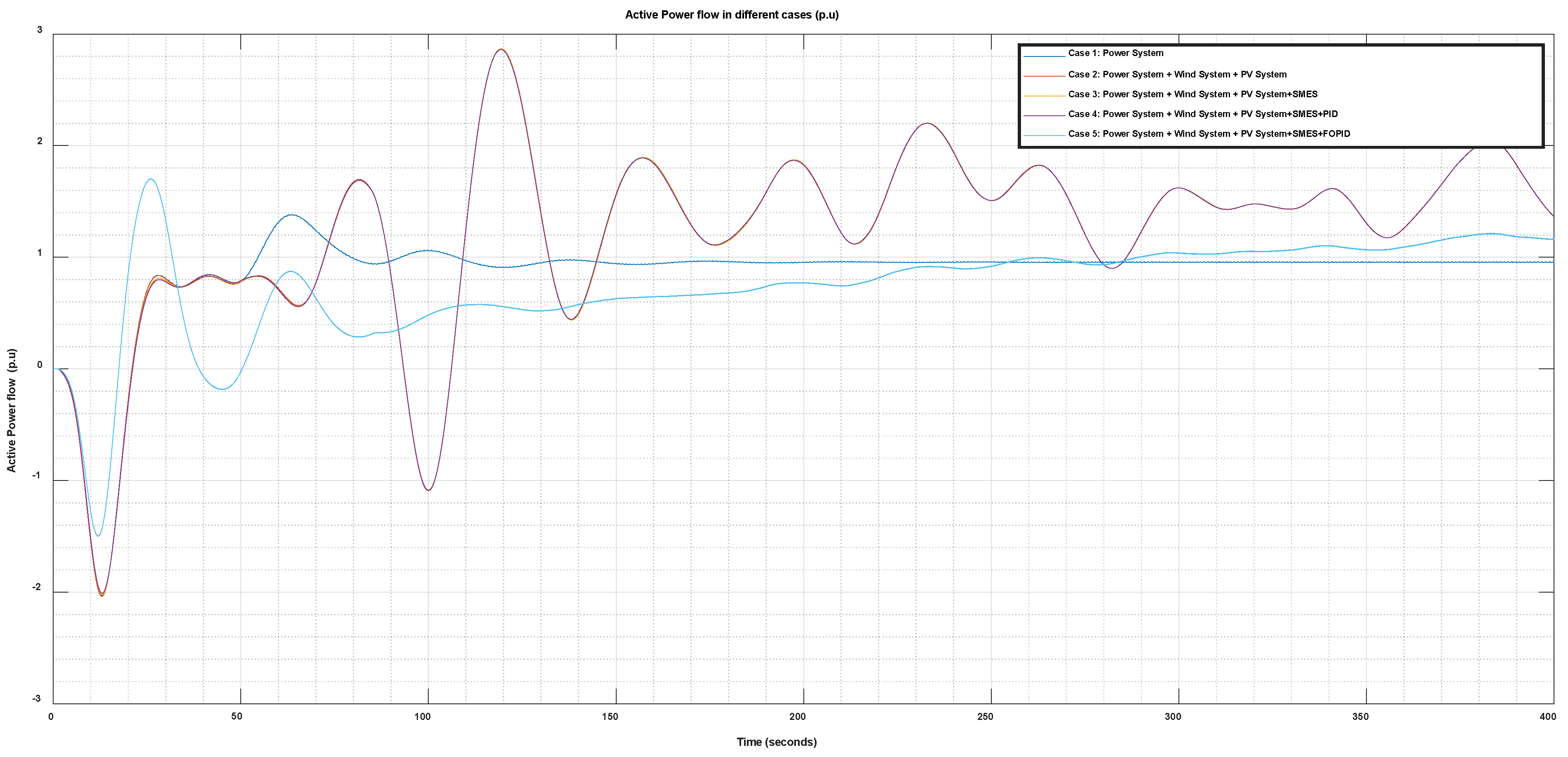
8.1.3. Power System with PV and Wind Turbine Scenario
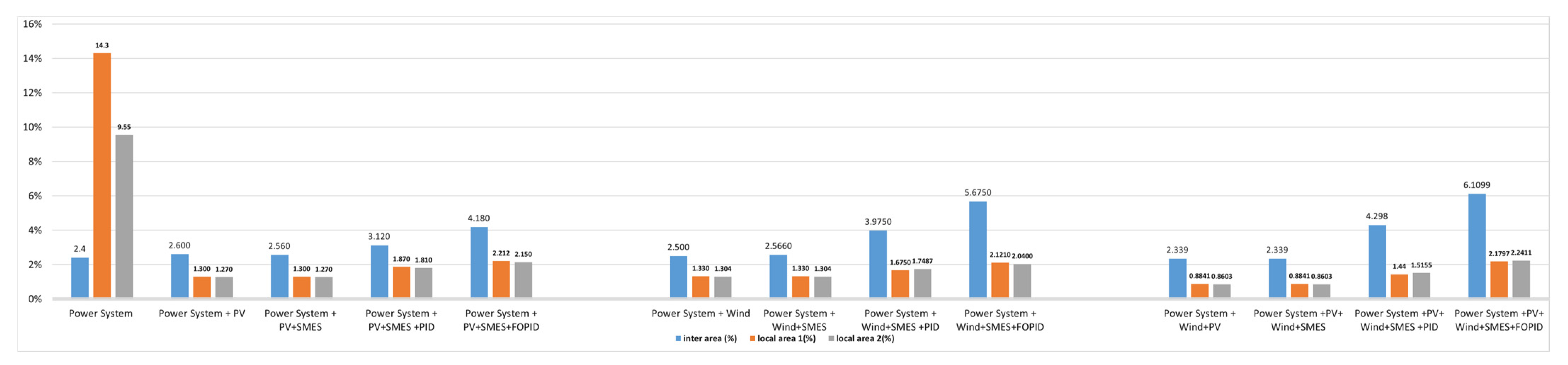
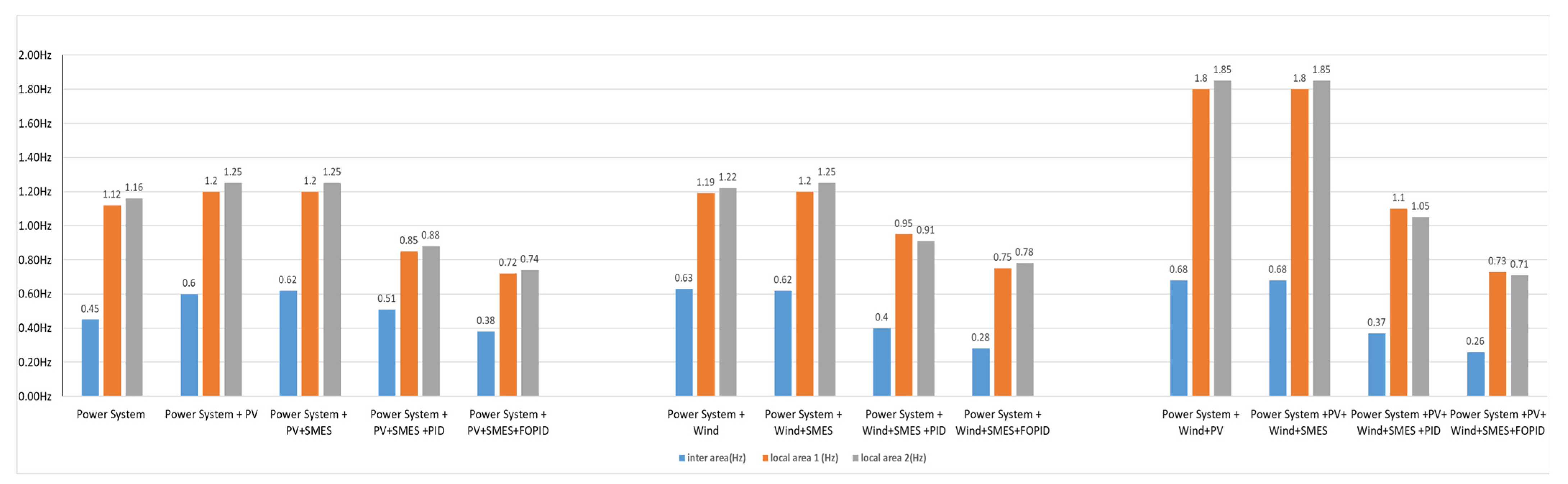
8.2. Analysis of Eigenvalues
9. Conclusions
Author Contributions
Funding
Conflicts of Interest
References
- Masson-Delmotte, V.; Zhai, P.; Chen, Y.; Goldfarb, L.; Gomis, M.I.; Matthews, J.B.R.; Berger, S.; Huang, M.; Yelekçi, O.; Yu, R.; et al. Working Group I Contribution to the Sixth Assessment Report of the Intergovernmental Panel on Climate Change; IPCC: Geneva, Switzerland, 2021; ISBN 9789291691586. [Google Scholar]
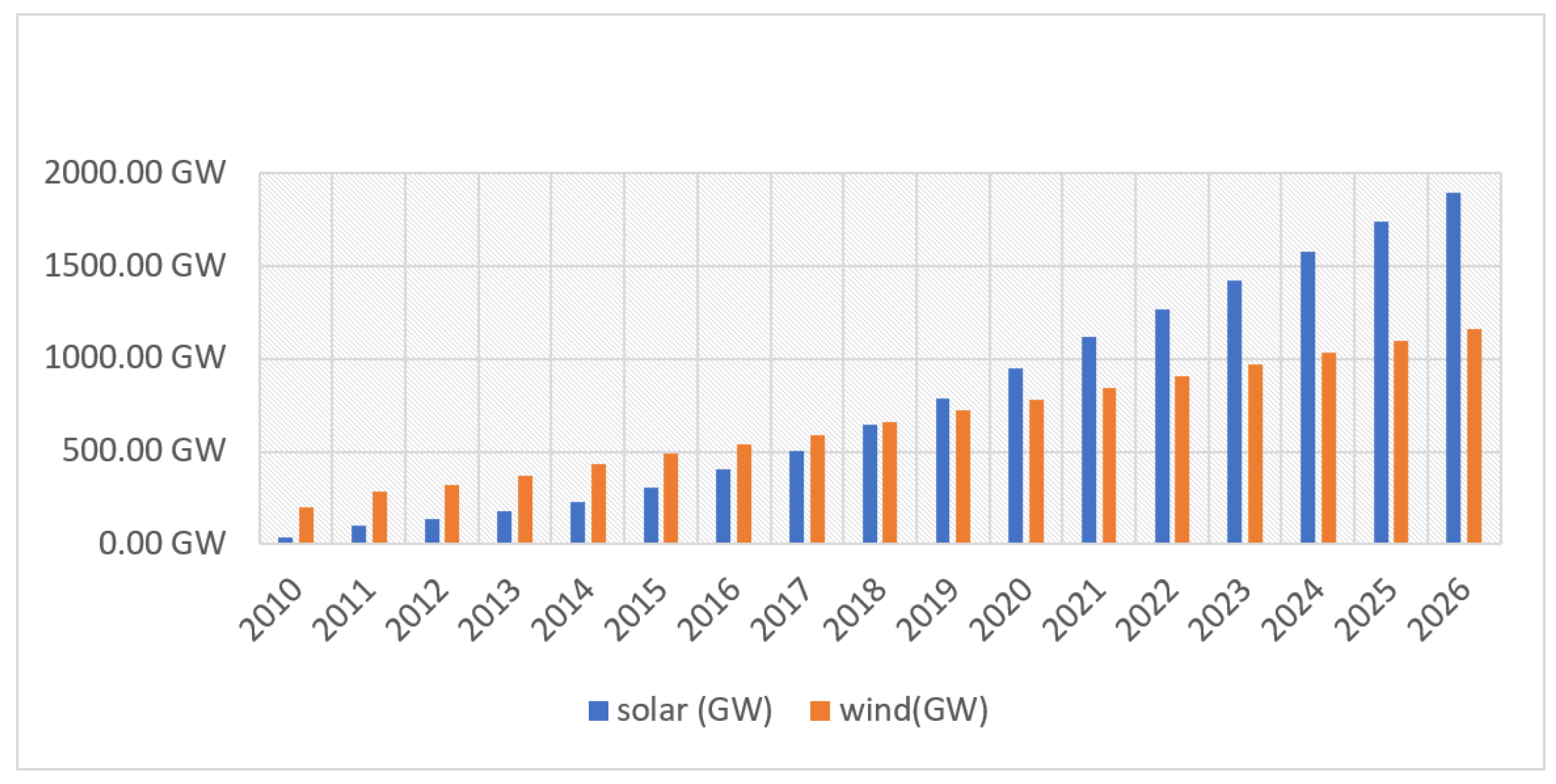
- Energy Agency, I. Renewables 2021—Analysis and Forecast to 2026; International Energy Agency: Paris, France, 2021. [Google Scholar]
- Shafiul Alam, M.; Al-Ismail, F.S.; Salem, A.; Abido, M.A. High-Level Penetration of Renewable Energy Sources into Grid Utility: Challenges and Solutions. IEEE Access 2020, 8, 190277–190299. [Google Scholar] [CrossRef]
- Impram, S.; Varbak Nese, S.; Oral, B. Challenges of Renewable Energy Penetration on Power System Flexibility: A Survey. Energy Strategy Rev. 2020, 31, 100539. [Google Scholar] [CrossRef]
- Kundur, P.; Paserba, J.; Ajjarapu, V.; Andersson, G.; Bose, A.; Canizares, C.; Hatziargyriou, N.; Hill, D.; Stankovic, A.; Taylor, C.; et al. Definition and Classification of Power System Stability. IEEE Trans. Power Syst. 2004, 19, 1387–1401. [Google Scholar] [CrossRef]
- Shah, R.; Mithulananthan, N.; Bansal, R.C. Damping Performance Analysis of Battery Energy Storage System, Ultracapacitor and Shunt Capacitor with Large-Scale Photovoltaic Plants. Appl. Energy 2012, 96, 235–244. [Google Scholar] [CrossRef]
- Vural, A.M. Contribution of High Voltage Direct Current Transmission Systems to Inter-Area Oscillation Damping: A Review. Renew. Sustain. Energy Rev. 2016, 57, 892–915. [Google Scholar] [CrossRef]
- Abumeteir, H.A.; Vural, A.M. Impact of High Penetration Renewable Energy Systems on Low-Frequency Oscillations. In Proceedings of the 2021 International Conference on Electric Power Engineering–Palestine (ICEPE-P), Gaza, Palestine, 23–24 March 2021; IEEE: Piscataway, NJ, USA, 2021; pp. 1–4. [Google Scholar]
- Sui, X.; Tang, Y.; He, H.; Wen, J. Energy-Storage-Based Low-Frequency Oscillation Damping Control Using Particle Swarm Optimization and Heuristic Dynamic Programming. IEEE Trans. Power Syst. 2014, 29, 2539–2548. [Google Scholar] [CrossRef]
- Setiadi, H.; Krismanto, A.U.; Mithulananthan, N.; Hossain, M.J. Modal Interaction of Power Systems with High Penetration of Renewable Energy and BES Systems. Int. J. Electr. Power Energy Syst. 2018, 97, 385–395. [Google Scholar] [CrossRef]
- Beza, M.; Bongiorno, M. An Adaptive Power Oscillation Damping Controller by STATCOM with Energy Storage. IEEE Trans. Power Syst. 2015, 30, 484–493. [Google Scholar] [CrossRef]
- Zhu, Y.; Liu, C.; Wang, B.; Sun, K. Damping Control for a Target Oscillation Mode Using Battery Energy Storage. J. Mod. Power Syst. Clean Energy 2018, 6, 833–845. [Google Scholar] [CrossRef] [Green Version]
- Datta, U.; Kalam, A.; Shi, J. Battery Energy Storage System Control for Mitigating PV Penetration Impact on Primary Frequency Control and State-of-Charge Recovery. IEEE Trans. Sustain. Energy 2020, 11, 746–757. [Google Scholar] [CrossRef] [Green Version]
- Setiadi, H.; Mithulananthan, N.; Shah, R. Design of Wide-Area POD with Resiliency Using Modified DEA for Power Systems with High Penetration of Renewable Energy. IET Renew. Power Gener. 2019, 13, 342–351. [Google Scholar] [CrossRef]
- Setiadi, H.; Mithulananthan, N.; Shah, R.; Lee, K.Y.; Krismanto, A.U. Resilient Wide-Area Multi-Mode Controller Design Based on Bat Algorithm for Power Systems with Renewable Power Generation and Battery Energy Storage Systems. IET Gener. Transm. Distrib. 2019, 13, 1884–1894. [Google Scholar] [CrossRef]
- Ma, J.; Wang, T.; Thorp, J.S.; Wang, Z.; Yang, Q.; Phadke, A.G. WAMS Based Damping Control of Inter-Area Oscillations Employing Energy Storage System. Adv. Electr. Comput. Eng. 2012, 12, 33–40. [Google Scholar] [CrossRef]
- Neely, J.C.; Byrne, R.H.; Elliott, R.T.; Silva-Monroy, C.A.; Schoenwald, D.A.; Trudnowski, D.J.; Donnelly, M.K. Damping of Inter-Area Oscillations Using Energy Storage. In Proceedings of the 2013 IEEE Power & Energy Society General Meeting, Vancouver, BC, Canada, 21–25 July 2013. [Google Scholar] [CrossRef]
- Bamasak, S.M.; Kumar, S.R.; Al-Turki, Y.A. Design of Wide Area Fractional-Order PID Damping Controller for Inter-Area Low-Frequency Oscillations Using Differential Evolution. J. Eng. Res. 2018, 6, 94–115. [Google Scholar]
- He, T.; Li, S.; Wu, S.; Li, K. Small-Signal Stability Analysis for Power System Frequency Regulation with Renewable Energy Participation. Math. Probl. Eng. 2021, 2021, 5556062. [Google Scholar] [CrossRef]
- Zhu, Y.; Liu, C.; Sun, K.; Shi, D.; Wang, Z. Optimization of Battery Energy Storage to Improve Power System Oscillation Damping. IEEE Trans. Sustain. Energy 2019, 10, 1015–1024. [Google Scholar] [CrossRef] [Green Version]
- Darvish Falehi, A. Optimal Robust Disturbance Observer Based Sliding Mode Controller Using Multi-Objective Grasshopper Optimization Algorithm to Enhance Power System Stability. J. Ambient Intell. Humaniz. Comput. 2020, 11, 5045–5063. [Google Scholar] [CrossRef]
- Kundur, P. Power System Stability and Control—McGraw-Hill Education; McGraw Hill: New York, NY, USA, 1994; ISBN 007035958X. [Google Scholar]
- Darvish Falehi, A. Optimal Fractional Order BELBIC to Ameliorate Small Signal Stability of Interconnected Hybrid Power System. Environ. Prog. Sustain. Energy 2019, 38, 13208. [Google Scholar] [CrossRef]
- Panda, S. Differential Evolutionary Algorithm for TCSC-Based Controller Design. Simul. Model. Pract. Theory 2009, 17, 1618–1634. [Google Scholar] [CrossRef]
- Lastomo, D.; Setiadi, H.; Djalal, M.R. Optimization of SMES and TCSC Using Particle Swarm Optimization for Oscillation Mitigation in a Multi Machines Power System. J. Mechatron. Electr. Power Veh. Technol. 2017, 8, 11–21. [Google Scholar] [CrossRef] [Green Version]
- Elmelegi, A.; Mohamed, E.A.; Aly, M.; Ahmed, E.M.; Mohamed, A.A.A.; Elbaksawi, O. Optimized Tilt Fractional Order Cooperative Controllers for Preserving Frequency Stability in Renewable Energy-Based Power Systems. IEEE Access 2021, 9, 8261–8277. [Google Scholar] [CrossRef]
- Alam, M.S.; Alotaibi, M.A.; Alam, M.A.; Hossain, M.A.; Shafiullah, M.; Al-Ismail, F.S.; Rashid, M.M.U.; Abido, M.A. High-Level Renewable Energy Integrated System Frequency Control with Smes-Based Optimized Fractional Order Controller. Electronics 2021, 10, 511. [Google Scholar] [CrossRef]
- Mohamed, E.A.; Ahmed, E.M.; Elmelegi, A.; Aly, M.; Elbaksawi, O.; Mohamed, A.A.A. An Optimized Hybrid Fractional Order Controller for Frequency Regulation in Multi-Area Power Systems. IEEE Access 2020, 8, 213899–213915. [Google Scholar] [CrossRef]
- Vigya; Mahto, T.; Malik, H.; Mukherjee, V.; Alotaibi, M.A.; Almutairi, A. Renewable Generation Based Hybrid Power System Control Using Fractional Order-Fuzzy Controller. Energy Rep. 2021, 7, 641–653. [Google Scholar] [CrossRef]
- Gupta, A.K.; Verma, K.; Niazi, K.R. Dynamic Impact Analysis of DFIG-Based Wind Turbine Generators on Low-Frequency Oscillations in Power System. IET Gener. Transm. Distrib. 2017, 11, 4500–4510. [Google Scholar] [CrossRef]
- Farhadi, M.; Mohammed, O. Energy Storage Technologies for High-Power Applications. IEEE Trans. Ind. Appl. 2016, 52, 1953–1962. [Google Scholar] [CrossRef]
- Setiadi, H.; Robandi, I.; Yuwono, T. Penalaan Parameter Superconducting Magnetic Energy Storage (SMES) Menggunakan Firefly Algorithm (FA) Pada Sistem Tenaga Listrik Multimesin. J. Tek. ITS 2014, 3, B12–B17. [Google Scholar] [CrossRef]
- Díaz-González, F.; Sumper, A.; Gomis-Bellmunt, O. Energy Storage in Power Systems; John Wiley & Sons: Hoboken, NJ, USA, 2016; ISBN 1118971329. [Google Scholar]
- Mchiri, L.; ben Makhlouf, A.; Baleanu, D.; Rhaima, M. Finite-Time Stability of Linear Stochastic Fractional-Order Systems with Time Delay. Adv. Differ. Eq. 2021, 2021, 1–10. [Google Scholar] [CrossRef]
- Latif, A.; Hussain, S.M.S.; Das, D.C.; Ustun, T.S.; Iqbal, A. A Review on Fractional Order (FO) Controllers’ Optimization for Load Frequency Stabilization in Power Networks. Energy Rep. 2021, 7, 4009–4021. [Google Scholar] [CrossRef]
- Elkasem, A.H.A.; Kamel, S.; Hassan, M.H.; Khamies, M.; Ahmed, E.M. An Eagle Strategy Arithmetic Optimization Algorithm for Frequency Stability Enhancement Considering High Renewable Power Penetration and Time-Varying Load. Mathematics 2022, 10, 854. [Google Scholar] [CrossRef]
- Saadatmand, M.; Mozafari, B.; Gharehpetian, G.B.; Soleymani, S. Optimal PID Controller of Large-Scale PV Farms for Power Systems LFO Damping. Int. Trans. Electr. Energy Syst. 2020, 30, e12372. [Google Scholar] [CrossRef]
- Ahmed, E.M.; Elmelegi, A.; Shawky, A.; Aly, M.; Alhosaini, W.; Mohamed, E.A. Frequency Regulation of Electric Vehicle-Penetrated Power System Using MPA-Tuned New Combined Fractional Order Controllers. IEEE Access 2021, 9, 107548–107565. [Google Scholar] [CrossRef]


| PID | FOPID | |
|---|---|---|
| Structure | Simple | Complex |
| No. of tuning parameters | 3: Kp, Ki, Kd | 5: Kp, Ki, Kd, µ, −λ |
| Accuracy | Low | High |
| Power of operation | 0 or 1 | Any positive integer |
| Effective with | Simple system | Complex system |
| PSO Parameters | Value |
|---|---|
| Size of the swarm | 50 |
| Maximum steps | 50 |
| PSO momentum | 0.9 |
| PSO parameter C1 | 1.2 |
| PSO parameter C2 | 0.12 |
| Optimized Value | |
|---|---|
| Parameter | Optimized Value |
| 0.63 | |
| 0.05303 | |
| 1.9688 | |
| λ | 0.73 |
| µ | 0.92 |
| Scenario # | Cases | Δw | P | ||
|---|---|---|---|---|---|
| OS | ST (s) | OS | ST (s) | ||
| Scenario 1 | Power System + PV | 0.118 | - | 0.255 | - |
| Power System + PV + SMES | 0.116 | 55 | 0.243 | - | |
| Power System + PV + SMES + PID | 0.058 | 35 | 0.053 | 20 | |
| Power System + PV + SMES + FOPID | 0.0608 | 15 | 0.033 | 13 | |
| Scenario 2 | Power System + Wind | 0.119 | - | 0.355 | - |
| Power System + Wind + SMES | 0.115 | 50 | 0.341 | - | |
| Power System + Wind + SMES + PID | 0.0707 | 20 | 0.051 | 25 | |
| Power System + Wind + SMES + FOPID | 0.066 | 10 | 0.032 | 11 | |
| Scenario 3 | Power System + Wind + PV | 0.1192 | - | 0.345 | - |
| Power System +PV+ Wind + SMES | 0.1177 | 60 | 0.333 | - | |
| Power System + PV+ Wind + SMES + PID | 0.0911 | 25 | 0.025 | 28 | |
| Power System + PV + Wind + SMES + FOPID | 0.0902 | 10 | 0.022 | 10 | |
| Error Criteria | ||||
|---|---|---|---|---|
| Cases 1 | ISE | ITSE | IAE | ITAE |
| Power System + PV + SMES + PID | 0.0000742 | 0.0000712 | 0.2203 | 1.982 |
| Power System + PV + SMES + FOPID | 0.0000954 | 0.0000559 | 0.2037 | 1.843 |
| Cases 2 | ISE | ITSE | IAE | ITAE |
| Power System + Wind + SMES + PID | 0.00000533 | 0.0004233 | 0.2223 | 2.223 |
| Power System + Wind + SMES + FOPID | 0.00000512 | 0.0000411 | 0.2038 | 2.038 |
| Cases 3 | ISE | ITSE | IAE | ITAE |
| Power System + PV + Wind + SMES + PID | 0.0000155 | 0.0009551 | 0.2732 | 2.732 |
| Power System + PV + Wind + SMES + FOPID | 0.0000144 | 0.0001176 | 0.2552 | 2.552 |
Publisher’s Note: MDPI stays neutral with regard to jurisdictional claims in published maps and institutional affiliations. |
© 2022 by the authors. Licensee MDPI, Basel, Switzerland. This article is an open access article distributed under the terms and conditions of the Creative Commons Attribution (CC BY) license (https://creativecommons.org/licenses/by/4.0/).
Share and Cite
Abumeteir, H.A.; Vural, A.M. Design and Optimization of Fractional Order PID Controller to Enhance Energy Storage System Contribution for Damping Low-Frequency Oscillation in Power Systems Integrated with High Penetration of Renewable Sources. Sustainability 2022, 14, 5095. https://doi.org/10.3390/su14095095
Abumeteir HA, Vural AM. Design and Optimization of Fractional Order PID Controller to Enhance Energy Storage System Contribution for Damping Low-Frequency Oscillation in Power Systems Integrated with High Penetration of Renewable Sources. Sustainability. 2022; 14(9):5095. https://doi.org/10.3390/su14095095
Chicago/Turabian StyleAbumeteir, Hasan Ali, and Ahmet Mete Vural. 2022. "Design and Optimization of Fractional Order PID Controller to Enhance Energy Storage System Contribution for Damping Low-Frequency Oscillation in Power Systems Integrated with High Penetration of Renewable Sources" Sustainability 14, no. 9: 5095. https://doi.org/10.3390/su14095095