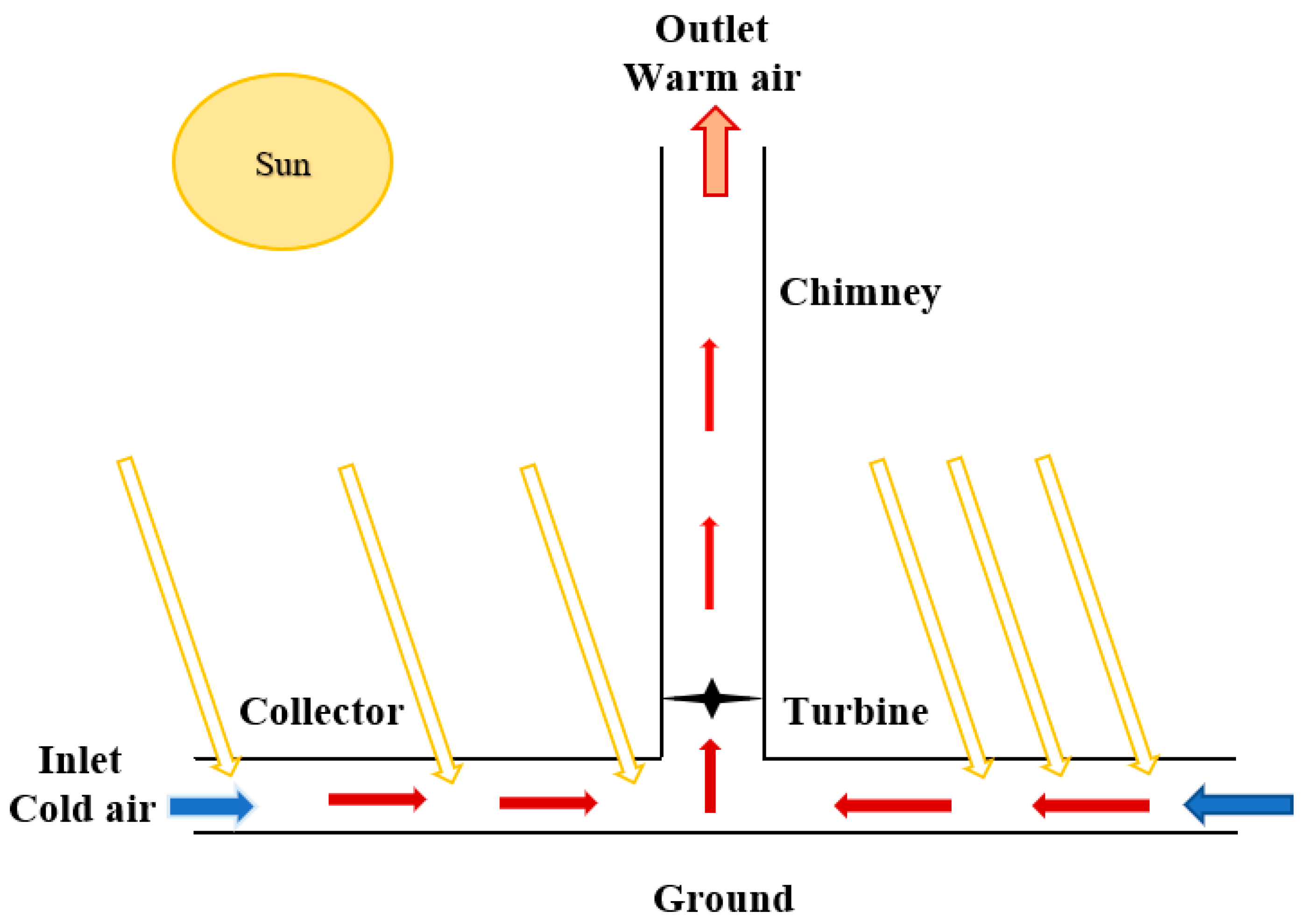
The collector is where solar radiation is absorbed in SCPP systems. The change in the collector’s geometry and design affects the system’s performance, as it will directly change the thermal energy entering the system. The studies in the literature will be examined separately according to their geometric and design effects. In SCPP systems, the chimney is the element of the structure positioned in the center of the collector; it creates a pressure difference due to its height. Thanks to the pressure difference it creates, it acts as a kind of system engine. The pressure difference is an essential factor because the power output of solar chimneys is directly caused by the system’s volumetric flow rate and pressure difference. The chimney and air velocity cause the pressure difference in the system. However, because the main component of the pressure difference is the chimney, the increase in the chimney’s height directly increases the pressure difference compared to Equation (2). In this section, firstly, studies in the literature will be given regarding the effect of the chimney height on the system. Because the change in the chimney’s diameter will affect the flow rate of the air in the system, the results of the difference in the diameter of the chimney will be included, and then the chimney profile will be continued.
5.1. Collector Radius
In the literature, the effect of the change in the collector radius on the system’s performance parameters, such as temperature, airflow rate, efficiency, and power output, has been repeatedly analyzed by many researchers. Considering the studies conducted, and given that changing the collector radius of the experimentally installed power plant is not allowed in most cases, the researchers mostly calculated the collector radius change’s effect on SCPP systems using mathematical, theoretical, and numerical analyses. Zhou et al. [
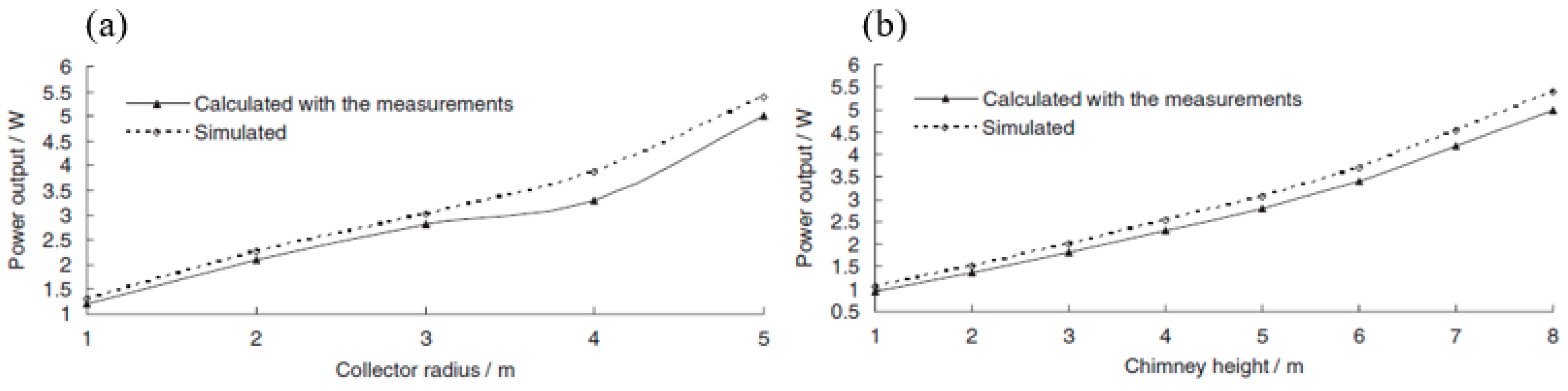
50] conducted experimental measurements on a small-scale SCPP model with 8-m high and 0.7 m diameter. By changing the collector radius at 850 W/m
2 radiation intensity, they claimed that the power output, which was 2.087 W at a 2-m collector radius, increased by 140% to 5.01 W in a collector with a 5-m radius. Ghalamchi et al. [
16] emphasized that the collector diameter increases the power output for the same geometry with their experimental data results. They stated that an SCPP system with a 500-m high chimney could give 468 kW power output with a collector of 420-m diameter. Al-Azawiey et al. [
69] experimentally studied an SCPP prototype with a 6.3-m high and 0.32-m diameter chimney, with collector diameters of 3 m and 6 m. They stated that the chimney’s air velocity was 1.56 m/s for a 3-m collector diameter and 806 W/m
2 radiation intensity, and 2.25 m/s at the chimney for a 6-m collector diameter and 808 W/m
2 radiation intensity. Although the radiation intensity is almost the same for both measurements, doubling the chimney’s diameter increases the airflow rate in the chimney by approximately 44.23%. Larbi et al. [
77] performed a performance analysis of a possible SCPP system installed in the Adrar region, which has a higher radiation intensity than other areas of Algeria, using a mathematical model. They claimed that the 200-m high, 10-m diameter chimney and a 500-m diameter collector SCPP system would provide between 140 and 200 kW of energy throughout the year. Designed with an 800 W/m
2 constant irradiance value and 30 °C initial temperature, the system gives a power output of approximately 142 kW with a collector diameter of 444 m; if the collector diameter is set to 690 m, the power output will increase by 140% to about 342 kW. Zhou et al. [
78] developed a simple mathematical model to analyze the SCPP system’s performance installed on the Qinghai–Tibet plateau. They claimed that a 1000 m high, 80-m diameter chimney and a 5650-m diameter collector system would give 100 MW power output at 800 W/m
2 radiation at 20 °C atmospheric temperature. The system, which has a 1000-m high chimney, gives 10 MW power output with a 1750-m diameter collector under the same conditions. It reaches 50 MW power output by providing four times more power output with a 3935-m diameter collector. Koonsrisuk et al. [
7] analyzed the Manzanares prototype with the detailed mathematical and CFD models. They compared the effect of the change in the chimney height ratio to the square of the collector radius on the system with two different models. The CFD model shows that the Manzanares prototype’s power output is 67–80 kW. They claimed that if the prototype H/R
2 ratio was 0.013 and the collector radius was 197.28 m at a fixed chimney height, the H/R
2 ratio would be 0.005 and the power output would be about 165 kW for both models. Similarly, they emphasized that the system’s mass flow rate will increase by 30%, from 765 kg/s in the reference state to 996 kg/s. Li et al. [
79] analyzed the Manzanares prototype’s performance when powered by a turbine, using a theoretical model they developed. They stated that while giving 53.5 kW power output at a 122-m collector radius in the reference conditions at 1000 W/m
2 radiation, if the collector radius is set to 244 m, the power output will increase by 120.5% to approximately 118 kW. They claimed that increasing the collector radius above 500.5 m would not increase the system’s power output.
Hamdan [
80] evaluated SCPP systems’ performance using the assumption of constant density, and compared the constant density model with a more realistic numerical discrete model that cares about the density change in the chimney. They showed that an SCPP system with a height of 1000 m and a chimney of a 100-m diameter would give a 35 MW power output with a collector of 1412-m diameter at 303 K ambient temperature with 263 W/m
2 radiation. If the collector diameter was set to 1778 m, the power output would be 50 MW. Gholamalizadeh and Mansouri [
81] analyzed solar chimneys using a comprehensive numerical model. In the results they obtained from the Kerman plant, they claimed that if the collector diameter was increased from 40 m to 80 m with a 60-m high and 3-m diameter chimney at 800 W/m
2 radiation, the mass flow would increase by approximately 43%, and the power output would increase by 233%. They emphasized that increasing the collector diameter will decrease the energy unit cost. Guo et al. [
82] analzed the performance of a large-scale solar chimney power plant that could be installed in Hami, China, which has the longest sunshine duration in a year, with a comprehensive theoretical model. They claimed that an SCPP system with a height of 1000 m and a chimney 120 m in diameter would deliver 100 MW of power output with a collector diameter of 5500 m at 300 K ambient temperature and 1000 W/m
2 radiation intensity. They showed that if the collector diameter was increased to 8000 m, the power output would increase by 51% to approximately 151 MW under the same conditions. Ngala et al. [
83] developed a mathematical model to estimate an SCPP system’s likely performance if it was to be installed in semi-arid regions of Nigeria, and analyzed the impact of geometric and environmental factors on the system. They stated that the system, installed with 700-m high, 10-m diameter chimney, can give 3.9 × 10
9 W power output with 800 W/m
2 radiation intensity and a 300-m collector diameter at 35 °C. They claimed that under the same conditions, the 600-m collector diameter power output could be 15.6 × 10
9 W. They also predicted that the system would produce an average of 3000 MW power per month throughout the year with a collector diameter of 700 m. Khelifi et al. [
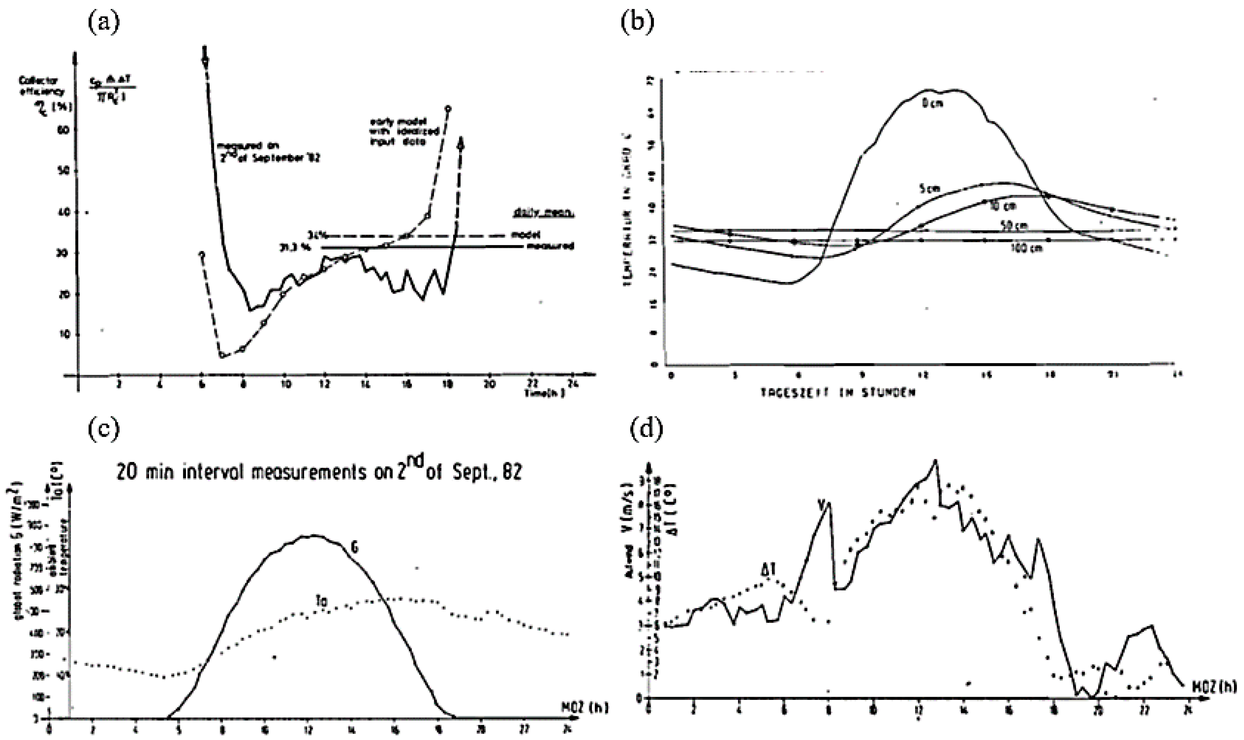
84] developed a mathematical model based on one-dimensional heat and mass transfer within the system to describe, optimize and evaluate SCPP systems’ performance (
Figure 14). They claimed that an SCPP model with a 100 m chimney height would deliver 0.25 MW of power with a 150 m radius collector at 1000 W/m
2 radiation and 298 K ambient temperature. They stated that the power output would be 1 MW with a 300 m radius collector under the same conditions. Choi et al. [
34] developed an analytical model to analyze the effect of geometric parameters and energy storage units on SCPP systems’ performance. The effect of the collector radius change on an SCPP system’s power output with a 1000-m high, 200-m diameter chimney and a 5-m collector entrance height on 1000 W/m
2 solar radiation and 20 °C stable climate conditions were analyzed. They claimed that under the same conditions when the collector radius was 1500 m, the power output, which was 51 MW, would be approximately 109.5 MW if the collector radius was set to 3000 m, thus exceeding the power output twice. They also stated that the increase in the collector radius would decrease the rate of increase in the system’s power output after 3000 m, and would have a negative effect on the system after a certain point. Nouar et al. [
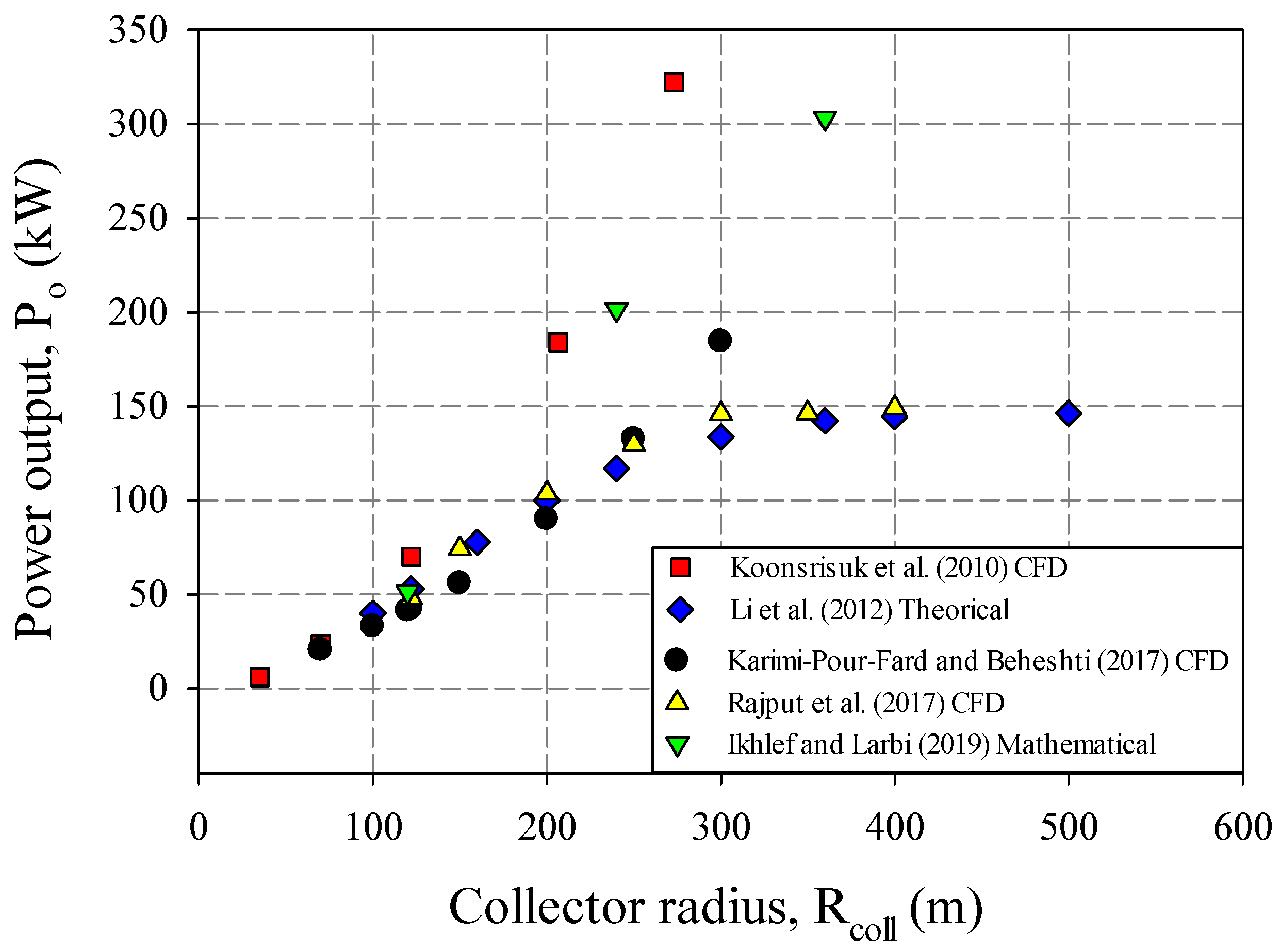
85] analyzed SCPP systems using a theoretical model they developed. The chief predicted the power output to be established with Manzanares’ data in the Algeria region under the region’s climatic conditions. In June, they claimed that at noon in Manzanares’ geometry, it would give 71 kW of power with a 100-m collector radius, and 106 kW at a 122-m prototype radius; at a 200-m collector radius, the power output would exceed 260 kW. Ikhlef and Larbi [
86] used a numerical model of the Manzanares prototype to analyze the effect of the use of energy storage units in SCPP systems on system performance. Adrar claimed that in the simulations carried out in Algerian climatic conditions, the power output—which was approximately 50 kW at a collector radius of 120 m—would quadruple to reach 200 kW when the collector radius is 240 m. Ming et al. [
87] analyzed the Manzanares prototype with a 3D numerical study. They showed that with a collector radius of 120 m in the reference geometry, the driving force is 167 Pa. The efficiency of the system is 0.715%. If the collector radius is 200 m, the driving force will be 272 Pa, and the efficiency will be 0.751%. Kalantar and Zare [
88] calculated the possible power output of the SCPP system installed in Yazd, Iran, with a 3D five-degree CFD model they developed from the Manzanares prototype. Unlike the reference geometry, they claimed that the system’s power output with a collector radius of 60 m was 28 kW. The collector radius was 240 m. It would exceed 110 kW, which is approximately four times the power output.
Karimi-Pour-Fard and Beheshti [
89] conducted a CFD study referencing the Manzanares pilot plant for optimum sizing, examining the energy storage unit and its geometric parameters’ effects on SCPP systems. Then, the model was evaluated for 24-h simulations of the climatic conditions in Isfahan, Iran. They claimed that the system gave 42 kW power output with 122 m collectors in Isfahan in July; however, with a 244-m collector radius, the power output would triple to approximately 126 kW. The reverse situation is the case for the efficiency of the system. They emphasized that while the overall efficiency is 0.68% in the reference geometry, when the radius is 244 m the overall efficiency will decrease by 35% to 0.44%. Rajput et al. [
90] developed a 2D model for the design and performance analysis of SCPP systems, and conducted a CFD study referencing the Manzanares prototype. They claimed that increasing the collector radius would improve the system’s mass flow, turbine pressure drop, air velocity at the turbine inlet, and power output. With a 122-m collector radius, the output power would be 48 kW. They emphasized that if the collector radius were 200 m under the same conditions, the power output would exceed 103 kW (
Figure 15). Bhoraniye et al. [
22] developed a CFD model to examine the effect of geometric parameters on SCPP systems’ performance. Referring to the Manzanares prototype’s dimensions, they claimed that increasing the collector radius up to 320 m at 1000 W/m
2 radiation intensity and 302 K ambient temperature would increase the airflow rate and the system’s power output. However, they claimed that the collector radius size of 395 m was the maximum power output point of the system; increasing the collector radius after this radius length would not improve the system’s performance.
Figure 14.
Different collector radius effects for a 100-m high chimney SCPP power output. Toghraie et al. [
91] and Khelifi et al. [
84].
Figure 14.
Different collector radius effects for a 100-m high chimney SCPP power output. Toghraie et al. [
91] and Khelifi et al. [
84].
Toghraie et al. [
91] analyzed the effect of geometric parameters on SCPP systems’ performance using the 3D CFD model they developed. They said that a solar chimney with 100 m height, a 8-m diameter chimney, and a 2-m height horizontal collector will obtain approximately 78 kW power output with 308 K ambient temperature under constant conditions with a 100-m collector radius in 800 W/m
2 solar radiation. They claimed that if the collector radius was set to 200 m under the same conditions, the power output would increase by 233% to approximately 260 kW. They emphasized that the contrary is in question for efficiency with a collector radius of 100 m under the same climatic conditions; the efficiency will decrease by 13%, and will be 0.26% at a collector radius of 0.3% and 200 m. They stated that the increase in the collector radius would increase the temperature in the collector. The comparative power outputs of the researchers studying the collector radius effect of an SCPP system with a 100-m high chimney are shown in
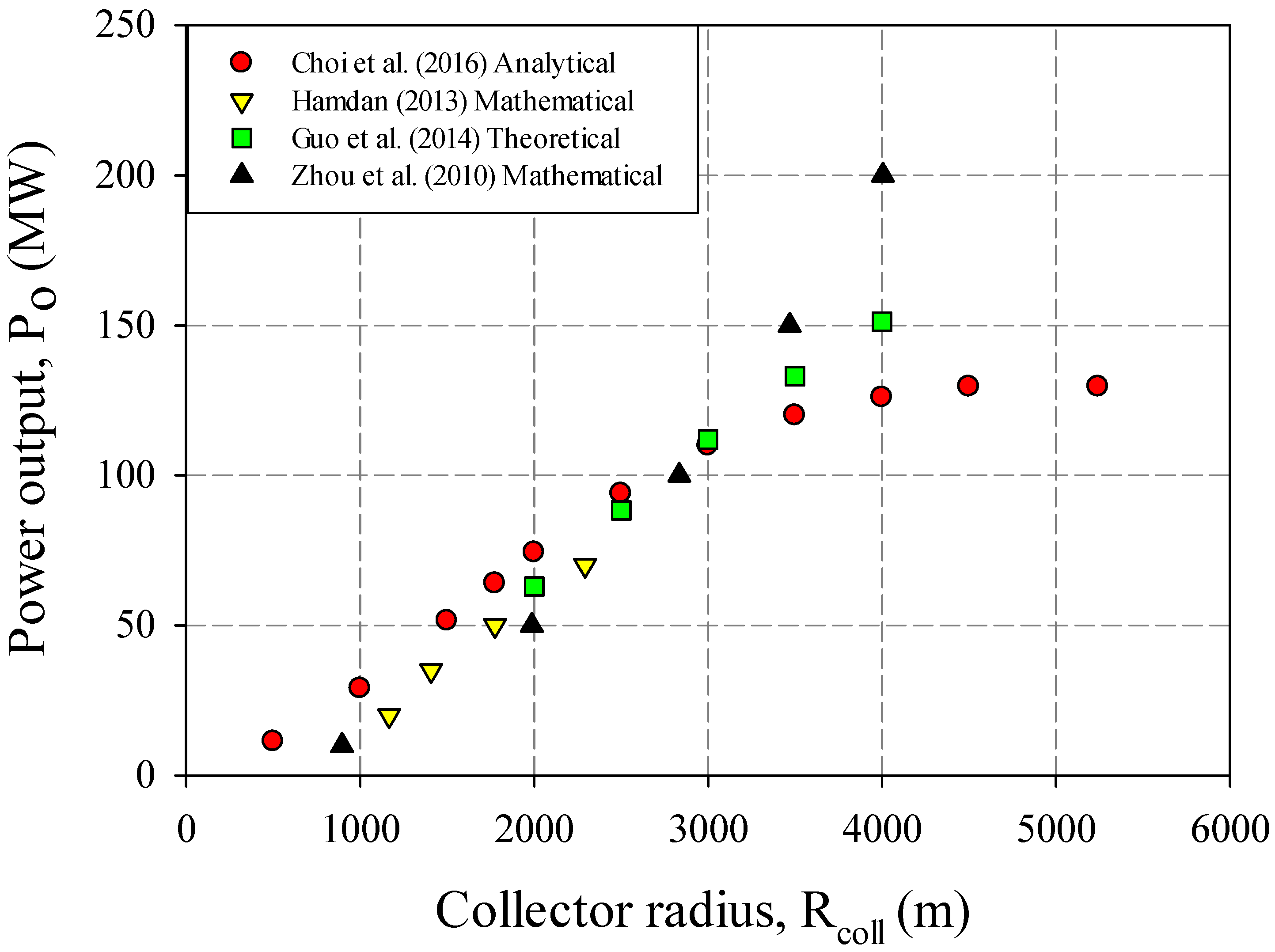
Figure 16. Similarly, the comparative graph of the power outputs for different collector radii is shown in
Figure 17 by taking the researchers’ Manzanares pilot plant’s measurements as a reference. The comparison of the studies in which some researchers analyzed the effect of the collector radius in different geometries and climate conditions for the system with a chimney of 1000-m height is given in
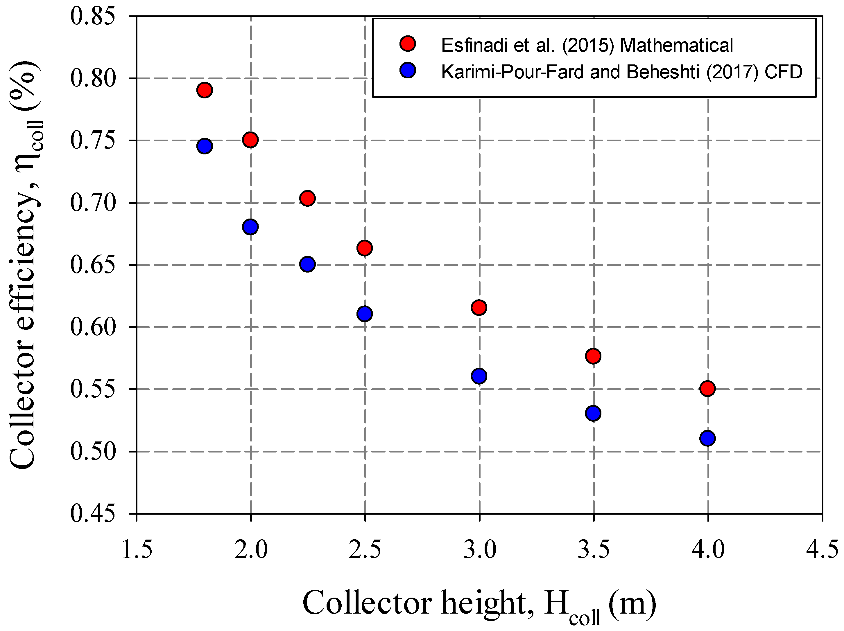
Figure 18. The researchers found that the change in the system’s collector radius affects the power output and other parameters. Esfidani et al. [
92] studied the effect of the design parameters on the system’s performance with a mathematical model developed based on the geometric dimensions of the Manzanares pilot plant. They stated that increasing the collector radius at 300 K ambient temperature will boost the system’s power output. The opposite is true for the efficiency; they claimed that the efficiency of 0.536% at the reference collector radius of 122 m would decrease by 40% to 0.3195% if the collector radius was set to 240 m (
Figure 17).
5.2. Collector Height
The collector is where both solar radiation and air enter the system. The change in the collector height is an essential geometric parameter determining SCPP systems’ performance. It affects the design’s airflow and the solar radiation transmitted to the ground. Najmi et al. [
61] evaluated the performance of SCPP systems with a MATLAB code they developed. Their analysis with Kerman prototype measurements stated that when the collector height is 1.5 m, the temperature difference in the system is 1 °C higher than the 2-m collector height. Ayadi et al. [
66] developed a CFD model to investigate the collector height’s effect on the temperature, pressure and velocity distribution by making the collector height 0.05, 0.10, 0.15 and 0.20 m. They claimed that increasing the collector height at 306 K ambient temperature and 800 W/m
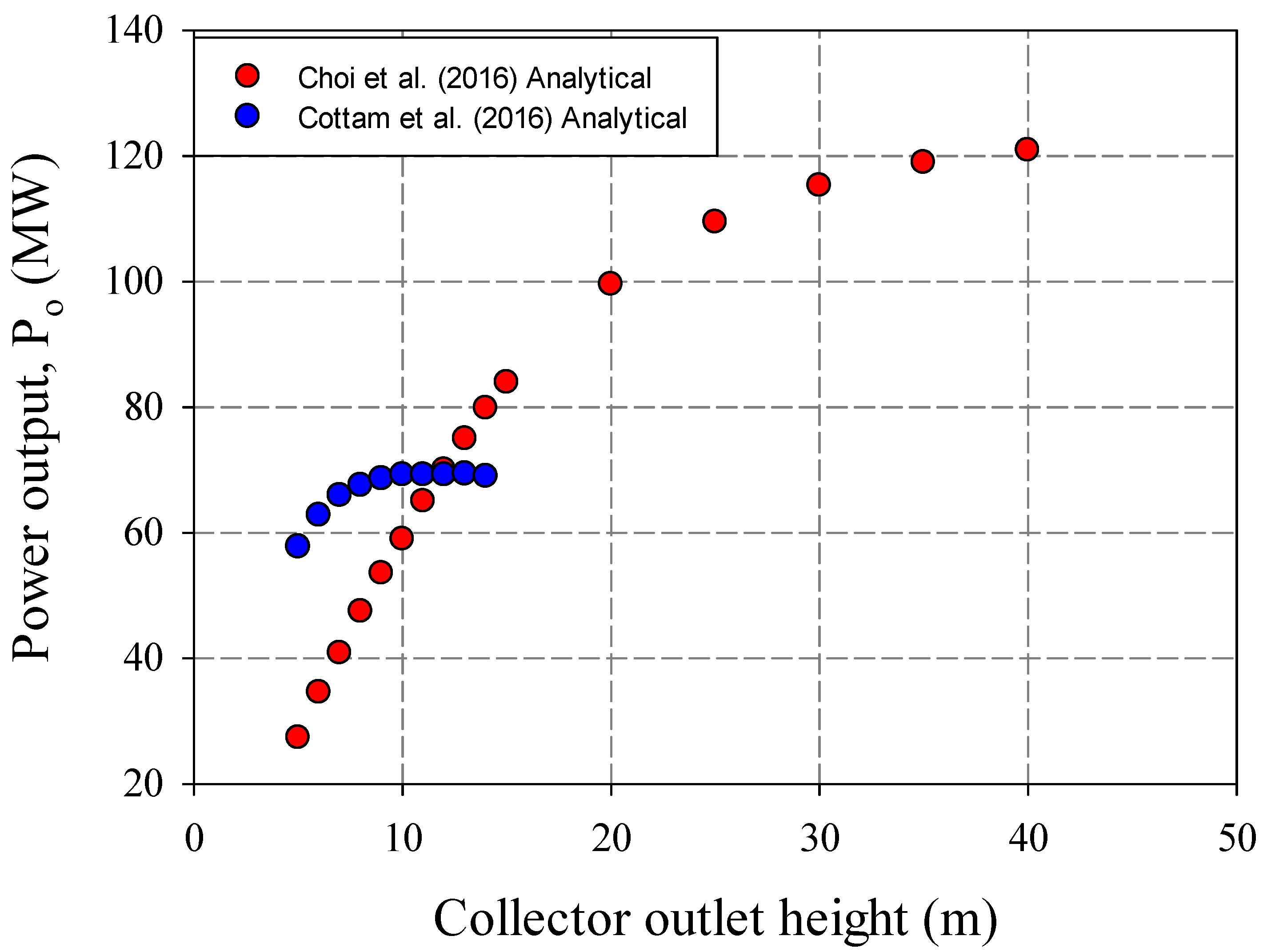
2 constant radiation would reduce the chimney inlet velocity from 2.4 m/s to 1.85 m/s, and reduce the power output by 33%. Cottam et al. [
93] designed a large-scale SCPP system with a 1000-m high, 55-m radius chimney and a 2150-m radius, 4-m entrance height collector, and analyzed the effect of the collector profile on the system using a steady-state analytical model. They stated that when the height of the horizontal collector is 4 m, the power output is 48.92 MW; when the collector height is 8 m, the power output will increase by 30% to 63.59 MW.
Dhahri et al. [
94] investigated the effect of geometric parameters on the Manzanares pilot plant system with a CFD study. At a constant 293 K ambient temperature and 800 W/m
2 radiation intensity, when the collector height is 1 m, the system temperature increase is 22.3 °C, and the mass flow is 949 kg/s; when the collector height is 3 m, the temperature increase decreases to 5.5 °C, while the mass flow is 1087 kg/s. They stressed that it would be released. Karimi-Pour-Fard and Beheshti [
89] Isfahan stated that increasing the collector height for the Manzanares prototype-sized SCPP system in Iranian climatic conditions would reduce the power output and efficiency of the system. They said that a system with a 2-m collector height in the reference state would have a 44 kW power output and 0.68% efficiency. They claimed that if the collector height is set to 3 m, the power output will decrease by 11.4% to 35.96 kW, and the efficiency would be reduced by 17.64% to 0.56%. Toghraie et al. [
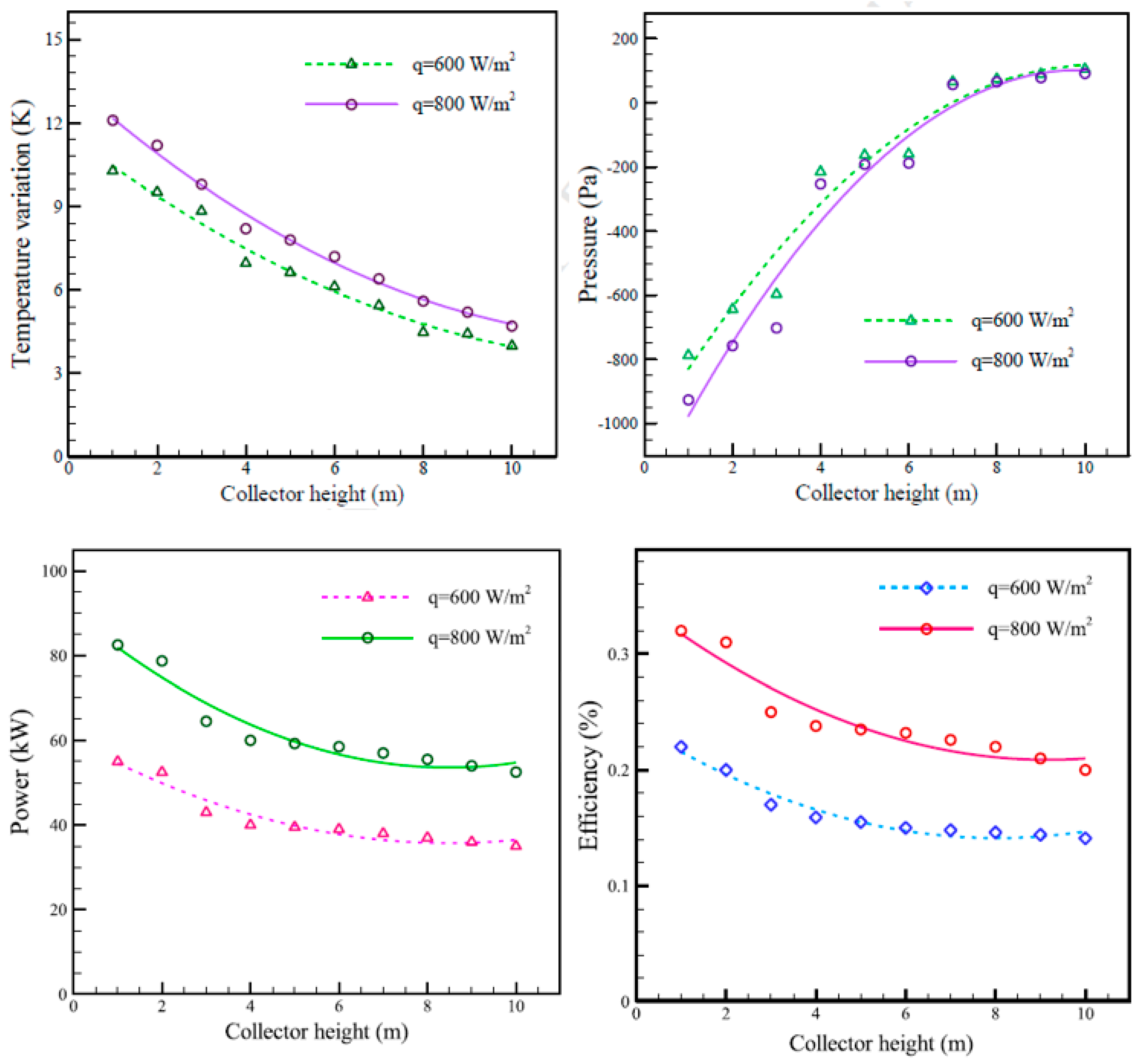
91] stated that, in the CFD model, 800 W/m
2 and 600 W/m
2 radiation values show that increasing the collector height decreases the power output, efficiency, pressure, and temperature change the system. They stated that in 800 W/m
2 constant radiation, 78.61 kW power output could be obtained with a 2-m collector height. They emphasized that when the collector height is set to 4 m, the power output will decrease by 23.6% to 60 kW; similarly, the system’s efficiency will decrease from 0.30% to 0.23%. Esfinadi et al. [
92] stated that increasing the collector height in the non-inclined collector will reduce the system’s power output and efficiency. The system’s efficiency is 0.79% at the reference height, and its power output is 298.387 kW. They claimed that if the collector height is set to 4 m, its efficiency would decrease by 26.6% to 0.55%, and the power output would be 211.29 kW, decreasing by 29.1%. Researchers generally accept that the collector height reduces the system’s efficiency in the analysis of the collector height of the Manzanares prototype. The comparative graphic is given in
Figure 19.
5.3. Collector SLOPE
Kasaeian et al. [
59] designed a small-scale system with a fixed collector outlet height of 1 m in an experimental study to analyze the effect of a change in the collector inlet height on SCPP systems. They stated that if the chimney entrance speed is 2.78 m/s at the collector entrance height of 5 cm at 25 °C ambient temperature, and if the collector entrance height is set to 15 cm, the chimney entry speed decreases by 16% and the temperature in the chimney decreases from 47.16 °C to 38.57 °C. Ghalamchi et al. [
16] measured the system’s effect with a fixed collector outlet height of 6 cm with a small-scale experimental SCPP system by setting the collector entrance heights at 6 cm, 8 cm and 12 cm. They stated that increasing the collector inlet height decreases the flowing air temperature, airflow rate and power output. Ayadi et al. [
95] analyzed the effect of collector slopes of 1, −1 and −1.5 degrees on the system with the CFD model with a collector of 2.75-m diameter and 0.05-m height and a chimney of 0.16-m diameter and 2.75-m height. They stressed that the divergent collector negatively affects the system at 800 W/m
2 constant radiation compared to the non-inclined collector. They emphasized that while the maximum air velocity was 2.13 m/s in the horizontal collector, it decreased to 1.89 m/s in a 1-degree divergent collector. However, they claimed that the convergent collector increased the maximum air velocity compared to the non-inclined collector with 2.31 m/s at −1 degree and 2.36 m/s at −1.5 degrees. They showed that a similar situation is valid for temperature and pressure distributions. Al-Kayiem and Al-Nakeeb [
96] evaluated the impact of the collector slope on the collector efficiency for four different seasons using the finite difference technique. They claimed that the −1 degree convergent-type collector’s collector efficiency was 124% higher in winter and 57.4% higher in summer than the horizontal collector. Gitan et al. [
97] studied the impact of the collector slope on the performance of a possible SCPP system in Malaysian climatic conditions based on the Manzanares pilot facility’s geometric measurements. They claimed the highest power output was obtained using a 10-degree collector, which is 3.5 kW more than that of the horizontal collector. They showed that the collector efficiency was 51% of the maximum, and the system’s efficiency was 0.165% of the maximum. Cottam et al. [
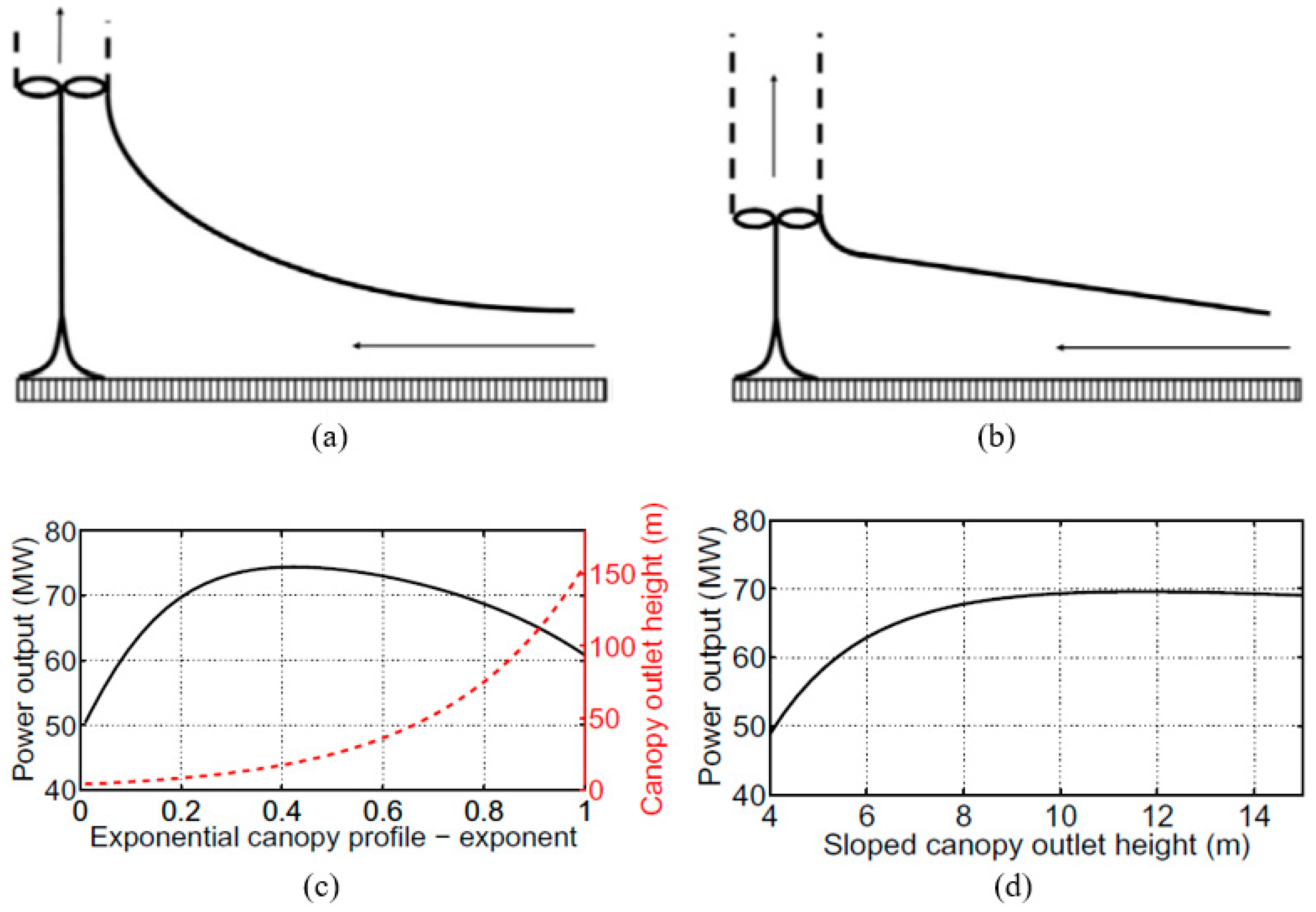
93] analyzed the impact of the collector profile on the SCPP system’s performance (
Figure 20). They designed a large-scale solar chimney with a 2150-m radius collector, 1000-m high, and a 55-m radius chimney with 4-m collector entrance height. In the calculations made with the steady-state analytical model, they claimed in
Figure 20 that the exponential and sloped collector gave a higher power output compared to the non-inclined collector. Still, it was an optimum point in both cases; after this point, the increase in the collector output height decreased the power output.
Choi et al. [
34] estimated the effect of the collector outlet height on a large-scale SCPP system’s performance. They stated that the system’s power output would be 27.81 MW for the non-inclined collector at a 5-m collector input height. They claimed that by making the collector output 25 m (collector slope = 0.380), the system’s power output would approximately triple, reaching 109.73 MW. Semai et al. [
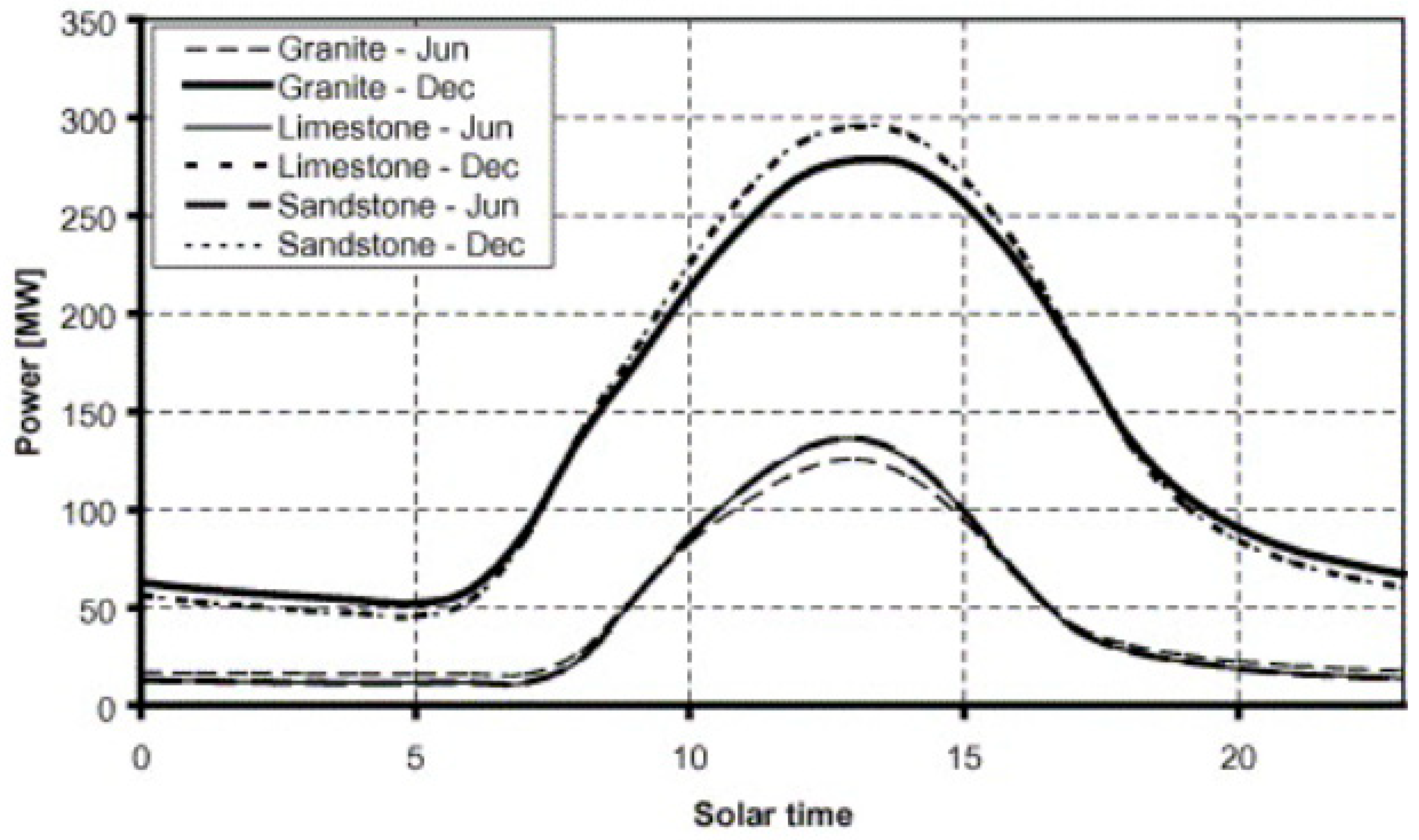
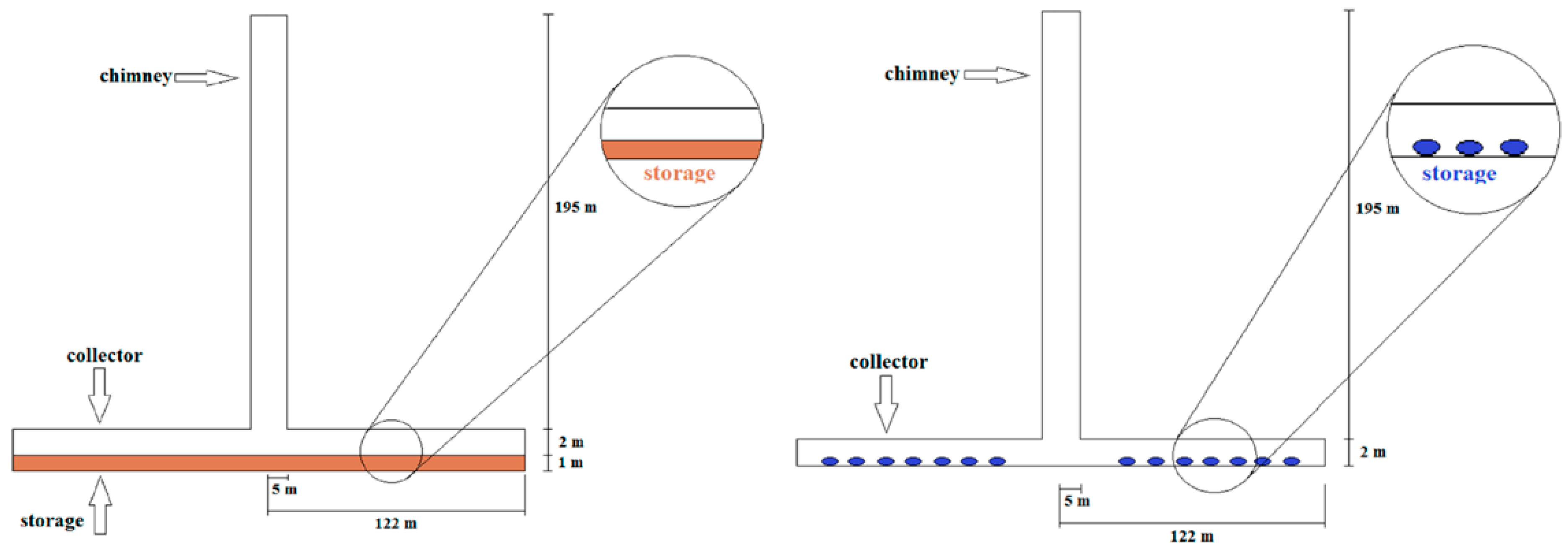
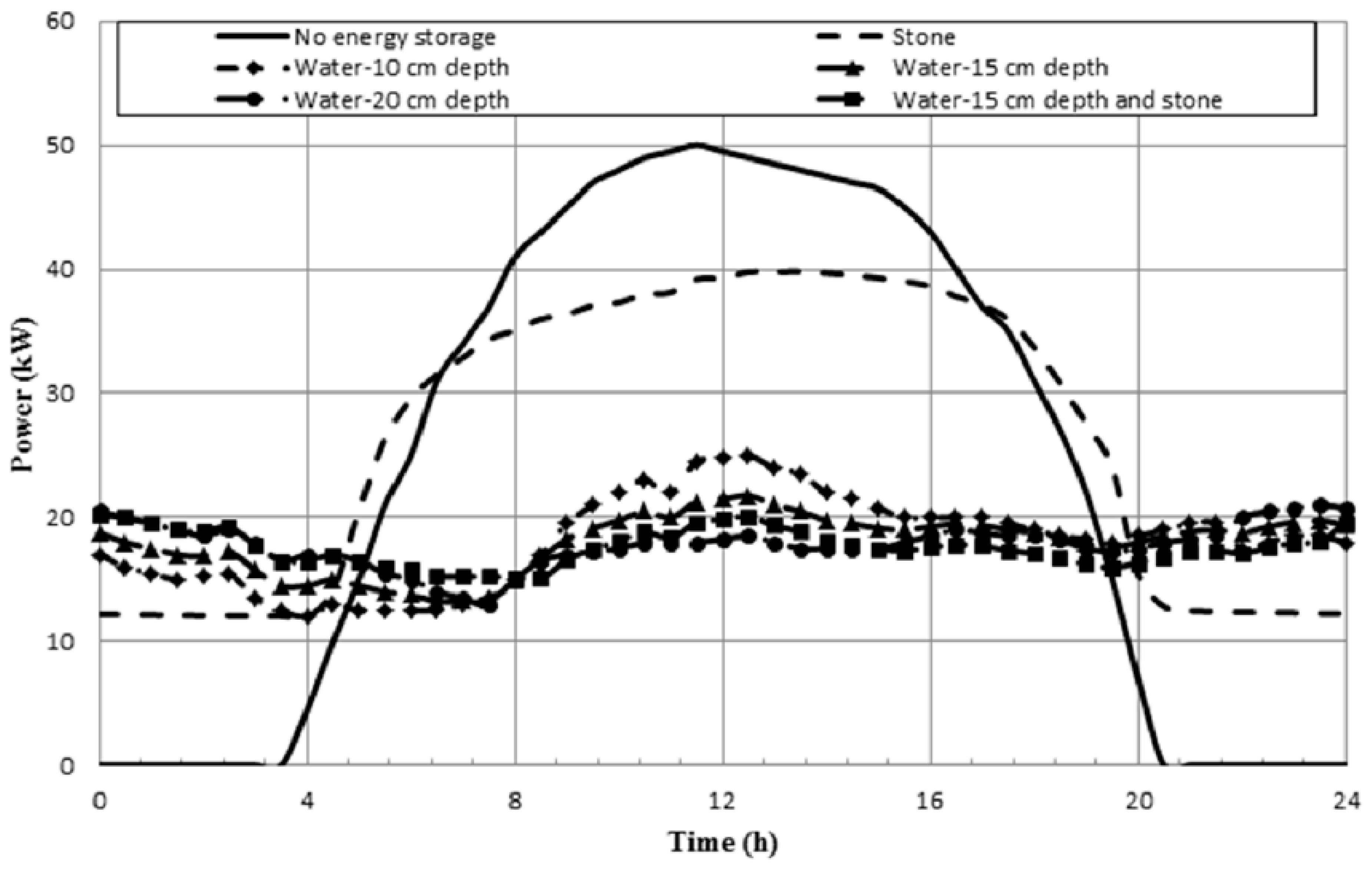
98], based on the Manzanares pilot plant’s geometric dimensions, conducted a numerical study to analyze the impact of the collector structure and the use of an additional energy storage layer ground on the performance of the SCPP system. The model Adrar, which was verified with the pilot plant’s experimental data, was predicted for the possible system to be established in the region by using the climatic conditions of Algeria. By making the collector inlet and outlet heights 2 m and 4 m, the convergent- and divergent-type collectors’ effects on the system were compared. Data for a 24-h power output are given in
Figure 21 [
98], comparing the performance of the SCPP1 tilt collector, the SCPP2 divergent collector, and the SCPP3 convergent collector. They claimed that the highest power output would be achieved in the convergent-type collector; compared to the non-slope condition, the maximum power output would be approximately 5% higher. They stated that a similar situation would be valid for the system’s efficiency as well. The convergent-type collector’s highest efficiency value is 0.45% at 17:00 during the day, and this value is approximately 18% more than the non-inclined collector. Gholamalizadeh and Kim [
99] studied the effect of the collector slope on SCPP systems by maintaining the collector inlet at a constant height of 1.85 m and changing the collector outlet height CFD model developed using the measurements of the Manzanares pilot plant. For a horizontal collector with a constant 300 K ambient temperature, 850 W/m
2 radiation intensity and a 1.85-m collector outlet height, the mass flow rate will be 727.31 kg/s, the collector efficiency will be 32.1%, and the power output will be 50.94 kW. They claimed that if the system’s collector outlet height was set to 3 m, the mass flow would increase to 759.63 kg/s, the collector efficiency would increase by 34.8%, and the power output would increase to 55.05 kW. They showed that increasing the collector outlet height from 3 m to 5 m would not affect the system. Karimi-Pour-Fard and Beheshti [
89] stated that by making the Manzanares pilot plant’s collector slope 2 degrees, the system’s power output would increase by 55%, from 44 kW to 70 kW. Hassan et al. [
100] conducted a CFD study of the Manzanares pilot plant’s measurements in order to examine the effect of the collector slope on the SCPP system. They claimed that assuming an ambient temperature of 303 K for 1 June at 13:00, increasing the collector slope would increase the airflow rate and the system’s mass flow.
Ahirwar and Sharma [
101] developed a CFD model with the Manzanares pilot plant’s geometric dimensions. The CFD model claimed the highest power output at a height of 190 m by applying a heat flux of 500 W/m
2 to the ground in the ground, and by changing the chimney height by 180–205 m. They investigated the effect of changing the collector slope in the range of 2–10 degrees, on the airflow rate and power output at the system’s chimney inlet. They claimed that if the system’s collector slope, which a had a 37.084 kW power output and a 9.31 m/s chimney input speed, was set to 40, the chimney input speed would increase by 13.69% to 10.38 m/s, and the power output would increase by 34.72% to 49.96 kW. They claimed that increasing the slope would adversely affect the system, reducing the power output and chimney entry speed. Gholamalizadeh and Kim [
102], in a geometric optimization study on previously established SCPP systems with mathematical modeling, claimed that using inclined collectors would give 15.85% more power output in the Kerman prototype and 27.73% more power in the Manzanares prototype. For the SCPP system with a height of 1000 m, the comparison of the power outputs of two systems with different chimney diameters and different collector radii according to the change of the collector output heights for 4-m and 5-m collector input heights is given in
Figure 22. There are various studies with different findings in the literature for the collector slope. In general, it is seen that there are different evaluations for the maximum performance according to the system geometry.
5.4. Chimney Height
Zhou et al. [
50] investigated the effect of the chimney height change of a small-scale SCPP system with a 0.7-m diameter chimney and a 5-m collector radius on the power output at a constant 850 W/m
2 radiation intensity using a mathematical model developed based on the experimental results. They stated that the power is 2.26 W at a 4-m chimney height, and if the chimney height is set to 8 m, the power output will increase by 118% to 4.94 W. Kasaeian et al. [
62] reported, in their experimental study, that the airflow velocity of 1.3 m/s at a 2-m chimney height was 4% more than the 1.354 m/s at a 3-m chimney height. Papageorgiou (2016) stated that the 15-m high and 2.5-m diameter SCPP system he built reached a maximum airspeed of 5 m/s with a collector area of 1020 m
2. He also indicated that the maximum airspeed becomes 6 m/s when the chimney’s height is increased to 24 m. Bernardes et al. [
27] developed an analytical and numerical comprehensive model that described solar chimneys’ performances. They stated that when the system’s chimney has a 3.5-m entrance height and a 4100-m diameter collector, a 1000-m height and 120-m diameter chimney is increased by 50%, and the daily power output would be 0.929 GWh. They also claimed that by increasing the chimney height by 100%, the daily power output would become 2016 GWh. Nizetic et al. [
42] developed a simplified model for the calculation of the power output that SCPP systems can generate in the Mediterranean region. They showed that the system’s chimney efficiency with a 200-m chimney with a collector diameter of 1250 m at 288 K ambient temperature is 0.698%, while the chimney efficiency will be 3.411% if the chimney height is set to 1000 m. Zhou et al. [
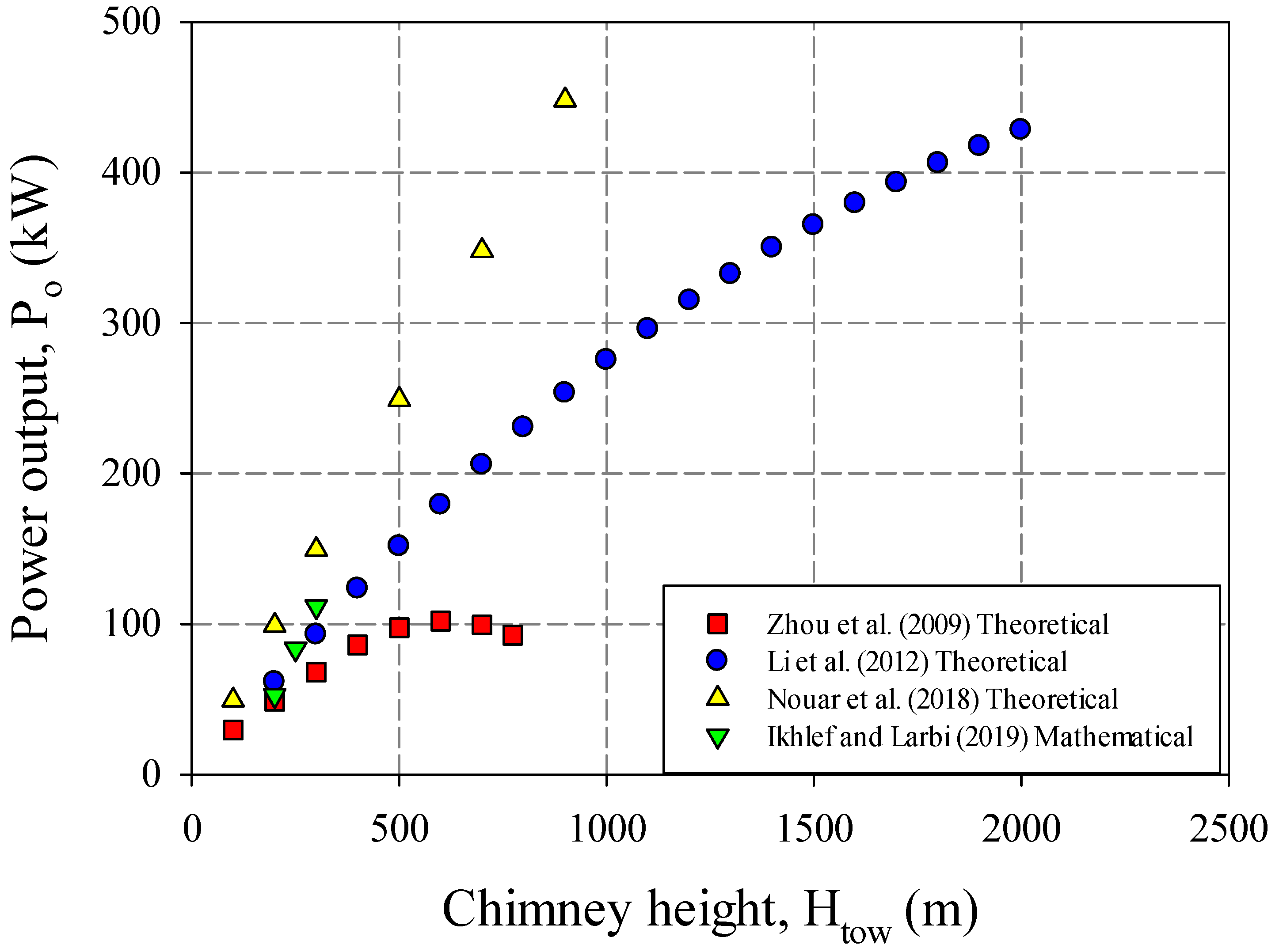
36] developed a theoretical model and analyzed the effect of the change in the Manzanares prototype’s height on the system. In experimental measurements, they claimed that at 1040 W/m
2 constant radiation, which is the highest radiation intensity, increasing the chimney height will increase the system’s power output up to 615 m and then reduce the power output. They emphasized that the maximum power output will be 102 kW at 615 m. Larbi et al. [
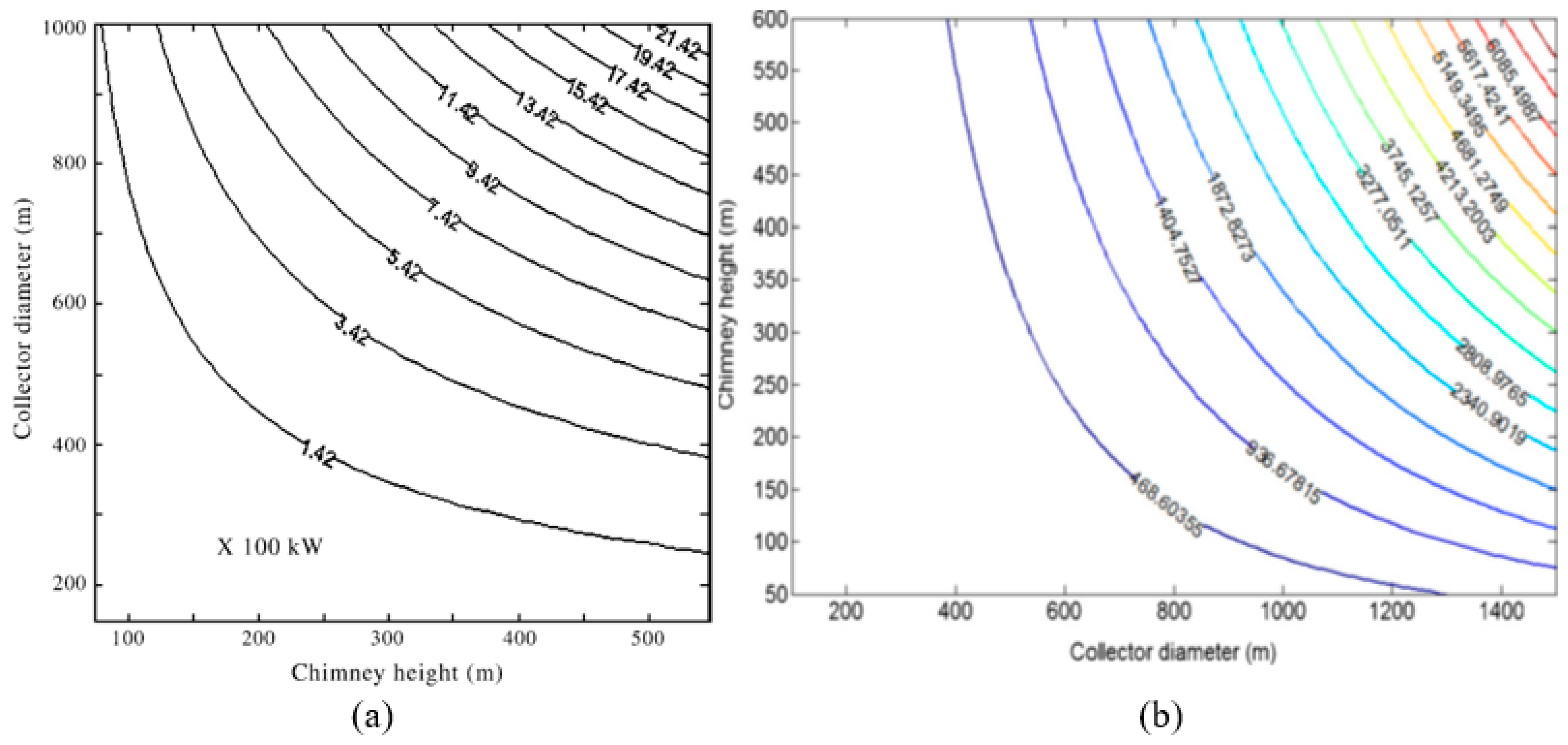
77] evaluated the effect of chimney height and collector diameter changes on the system, and designed a model with a 10-m diameter chimney and a 2.5-m collector height. They showed that the system would give 342 kW of power with a constant 800 W/m
2 radiation intensity, 600-m collector diameter, 250-m chimney height, and 300 K ambient temperature. They claimed that with a chimney height of 483 m, the power output would increase by 116.95% to 742 kW under the same conditions. They showed the increase in power output for different chimney heights and different collector diameters (
Figure 23a) [
77]. Sangi [
103] evaluated the SCPP system’s performance that was likely to be established in different cities in Iran using a simple numerical model depending on environmental and geometric variables.
Figure 23b [
103] shows that the power output will increase directly with the chimney height and the collector diameter, and that the high power outputs will occur with both parameters on a large scale. Koonsrisuk et al. [
7] only changed the chimney height and examined its effect on the system by maintaining the Manzanares prototype constant’s geometric parameters. They claimed that increasing the chimney’s height increases the system’s power output, and if the height is set to 296 m, the power output would be 180 kW. Al Alawin et al. [
104] simulated the effect of the chimney height on an SCPP system for Jordan’s geographic conditions. They stated that increasing the chimney height increases the volume flow, pressure difference, efficiency and airflow rate of a system with a 40-m collector diameter and a 3.5-m chimney diameter. They claimed that the power output would increase similarly, but that a maximum power output of 85 kW was obtained at the height of 210 m, after which an increase in chimney height would reduce the power output of the system. Li et al. [
79] claimed that the Manzanares prototype’s power output was 53.5 kW at 1000 W/m
2 constant radiation, and if the chimney height was set to 400 m, the power output would be 123.6 kW, increasing by 131%. Similarly, they showed that the higher the height, the higher the power output, exponentially. Hamdan [
80] stated that a system with a 100-m diameter chimney and a 2000-m collector diameter would give 5.81 MW power output with a 400-m high chimney at a constant radiation intensity of 263 W/m
2 and an ambient temperature of 303 K. They claimed that if the chimney height of the system was set to 800 m, the power output would increase by 179.8% to 16.26 MW. Similarly,
Figure 24a [
80] shows that the chimney’s height directly increases the power output in a constant radiation intensity. The 35 MW, constant power output shows the relationship between the collector radius and the chimney height in different radiation intensities in
Figure 24b [
80].
Ngala et al. [
83] stated that a SCPP system with a 700-m diameter collector and a 10 m fixed chimney diameter would deliver 1.5 × 10
9 W power output with a 300-m chimney at 350 °C ambient temperature and a constant 800 W/m
2 radiation intensity. With a chimney height of 600 m, the power output would be approximately 100% more than 3.02 × 10
9 W.
Nouar et al. [
85] estimated the Manzanares pilot plant’s performance in Chlef, Algeria, using a theoretical model. They claimed that the facility, if it were to be established in the region, would give 49.34 kW power output with a 100-m chimney at noon in June, while the power output would double this at 200 m, i.e., 99 kW. They emphasized that the power output will increase with the chimney’s height. Ikhlef and Larbi [
86] argued that an SCPP system likely to be installed in the size of the Manzanares pilot facility in the Algeria region would increase its performance by increasing the chimney height. They stated that it will give a power output of 52.5 kW at a height of 200 m, and a power output of 111.66 kW at a height of 300 m. Dhahri et al. [
94] analyzed the mass flow rate for different chimney heights of the Manzanares pilot plant at an ambient temperature of 293 K and a radiation intensity of 800 W/m
2 under constant climatic conditions. They emphasized that the mass flow, which is 1075.56 kg/s at a height of 200 m, would increase by 13.4% at 300 m and 1220 kg/s. Karimi-Pour-Fard and Beheshti [
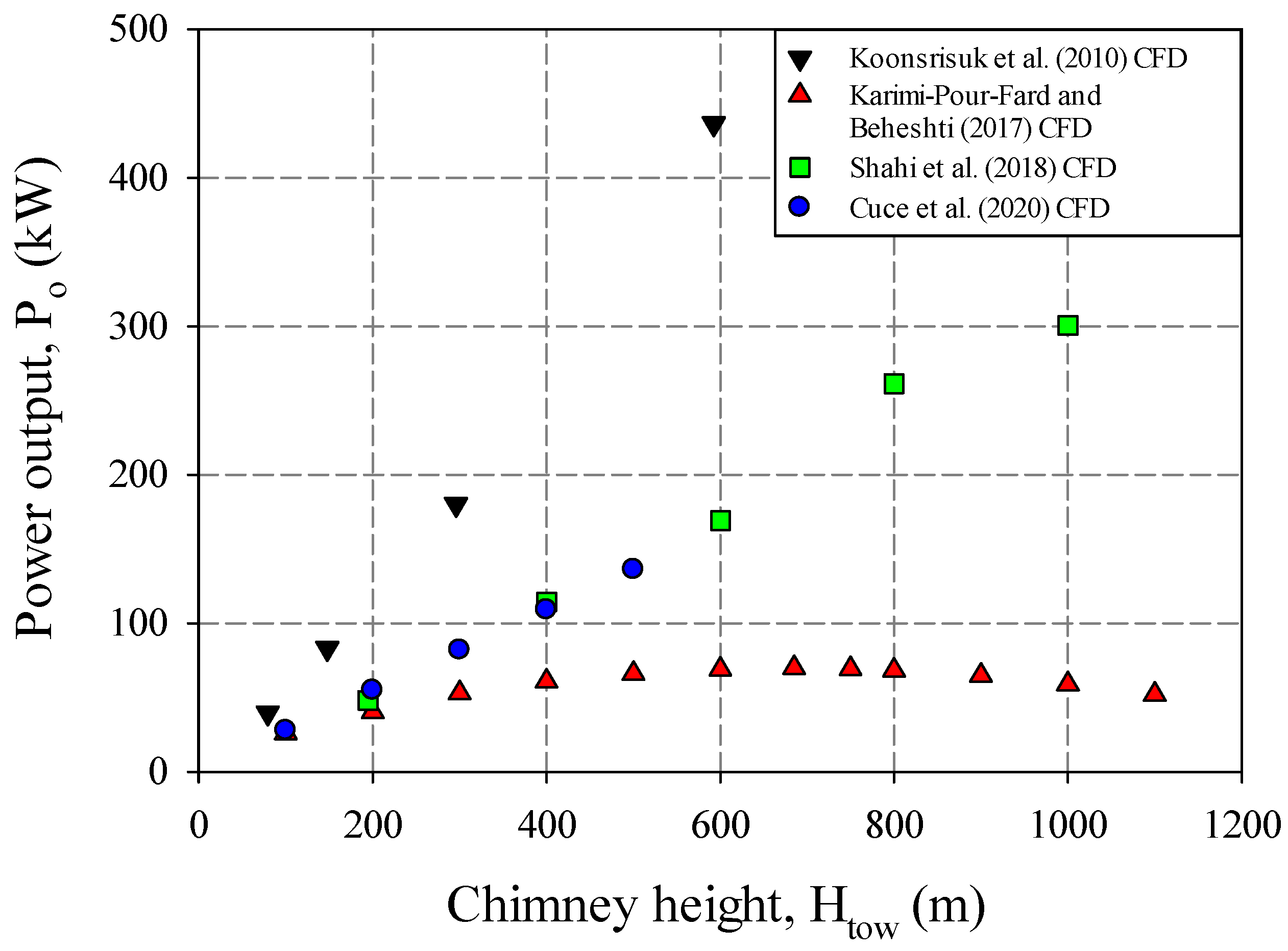
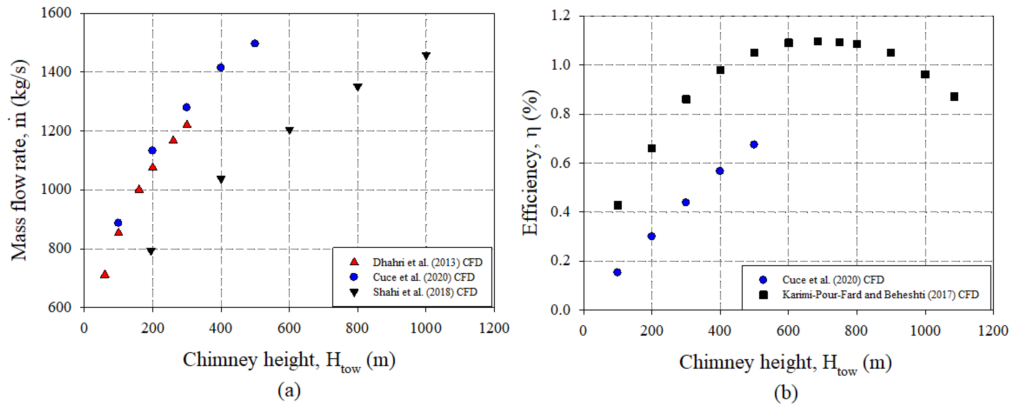
89] claimed that an increase in the Manzanares’s chimney height for Iranian climatic conditions would increase the system’s power output and efficiency up to 685 m; increasing the height would reduce the performance of the system. They explained that the system, which has a power output of 40.35 kW and an efficiency of 0.66% with a 200-m chimney, would achieve 60.85 kW power output and 0.98% efficiency at a height of 400 m. Shahi et al. [
105] developed a CFD model based on Manzanares’ geometry. They stated that it would give a power output of 48.04 kW at 1000 W/m
2 irradiance and 291.65 K ambient temperature. They emphasized that increasing the system’s chimney height would increase the mass flow, turbine pressure drop, turbine input speed, and power output. They claimed that at a 400-m chimney height, the power output would increase by 138% to 114,352 kW, while the mass flow would increase by 30% to 1,038,593 kg/s. Toghraie et al. [
91] developed a CFD model with a 100-m collector radius and an 8-m chimney diameter. They emphasized that increasing the chimney height at a constant 800 W/m
2 radiation intensity and 308 K ambient temperature of the SCPP system would increase the power output, efficiency, pressure difference and mass flow. They claimed that the power output of 24 kW at a 25-m chimney height would be 313.5 kW at a 500-m chimney height. Cuce et al. [
106] analyzed the effect of the chimney height on the system’s output by studying the Manzanares pilot plant. They showed that an increase in the chimney height increases the power output, efficiency, mass flow rate and pressure difference, and reduces the collector’s temperature increase. The change in the range of 100–500 m of the chimney height with 1000 W/m
2 radiation intensity and 293.15 K ambient temperature on the system is given in
Table 8. Based on the Manzanares prototype, the effect of the researchers’ chimney height on the system’s power output is shown in
Figure 25 with theoretical and mathematical studies. Similarly, a comparison of the CFD studies is given in
Figure 26. The study results of different researchers regarding the effect of the chimney height on the system’s mass flow and efficiency are presented in
Figure 27.
Khelifi et al. [
84] stated, in a numerical model, that the power output would be 1852.57 kW with a constant 1000 W/m
2 radiation intensity and a 200-m chimney at 298 K ambient temperature. They claimed that if the chimney were 400 m, the power output would be doubled to 3696.44 kW. Their results showed that the chimney’s height increases the power output linearly. Choi et al. [
34] argued in an analytical study that the power output of a large-scale SCPP system with a 100 m radius chimney and a 3000 m radius collector at a constant 1000 W/m
2 radiation intensity and 20 °C ambient temperature would increase with the chimney height. They stated that with a height of 500 m, the power output would be 42.25, and with a doubled height (1000 m), the power output would increase by 160% to 110 MW.
Similarly, researchers show that the increase in the chimney height increases the system’s performance with systems with different geometries [
107,
108].
5.5. Chimney Diameter
The researchers also emphasized that this change in the flue radius would increase the chimney cost from €100 M to €150 M at the same power output, while reducing the collector cost from €1700 M to €975 M, thus reducing the total cost. Choi et al. [
34] designed a solar chimney with a 1000-m chimney height, a 3000-m collector radius and a 100-m chimney diameter, with a maximum power output of 85 MW in an analytical model. They stated that increasing the chimney diameter exponentially increases the system’s power output to a certain level, decreasing the effect. They claimed that setting a chimney diameter of 200 m would increase the power output by 100% and provide about 170 MW. Ikhlef and Larbi [
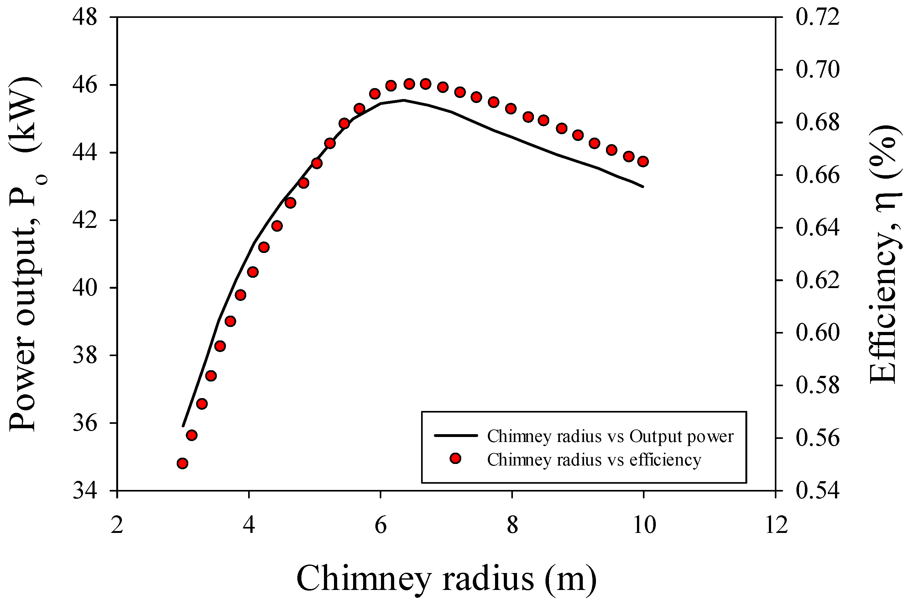
86] examined the effect of chimney diameter change on the system’s performance with a mathematical model based on the Manzanares prototype. They argued that changing a chimney diameter of 10 m to 30 m would increase the power output from 51.86 kW to 82.8 kW, i.e., by 60%. Karimi-Pour-Fard and Beheshti [
89] studied the impact of the chimney diameter on the Manzanares pilot plant’s possible performance in Isfahan, Iran, using the Ansys Fluent engineering software. They claimed that the maximum power output could be acheived at a chimney radius of 6.17 m and 45.48 kW, which was 3.7% more than the reference power value as shown in
Figure 28. Similarly, they argued that the system’s efficiency would increase by 4.5% to 0.69%.
Hamdan [
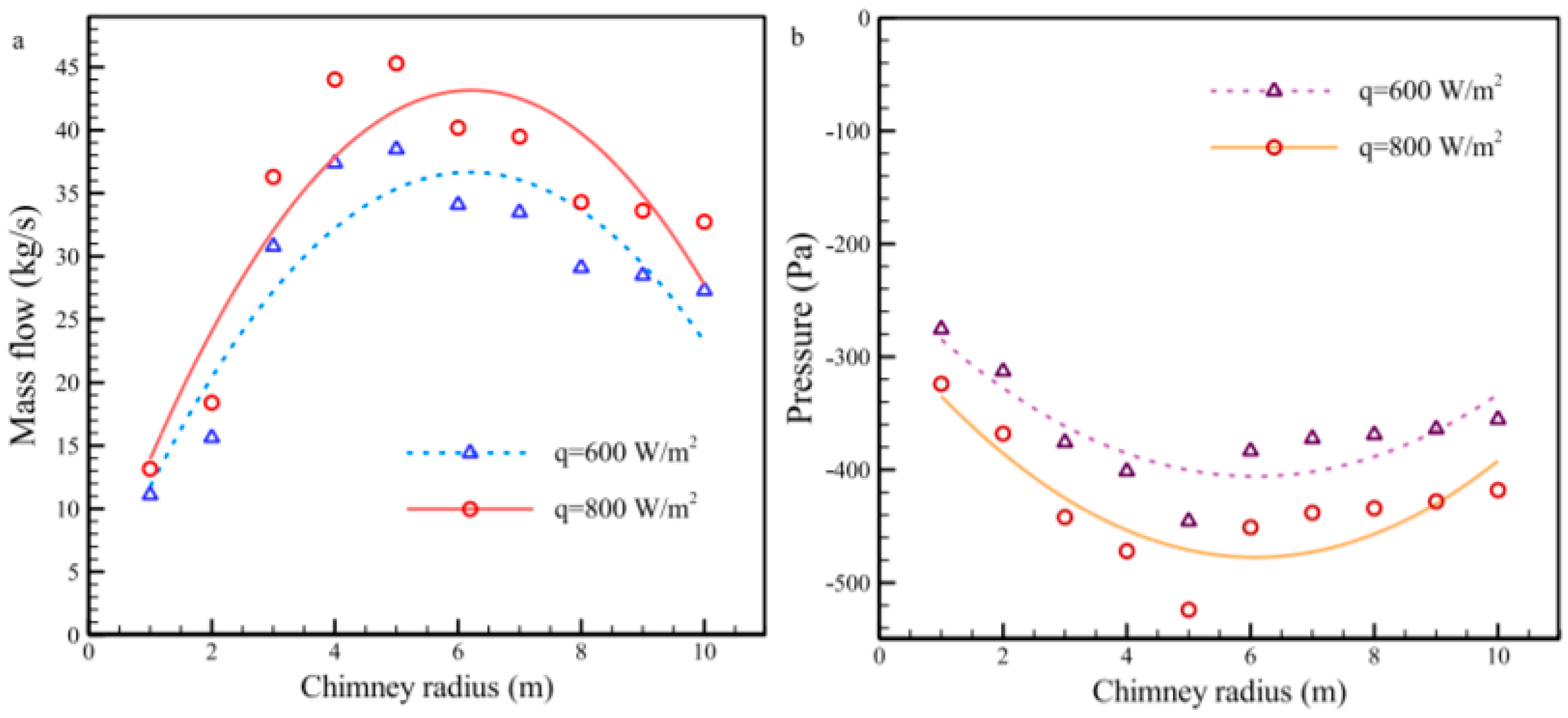
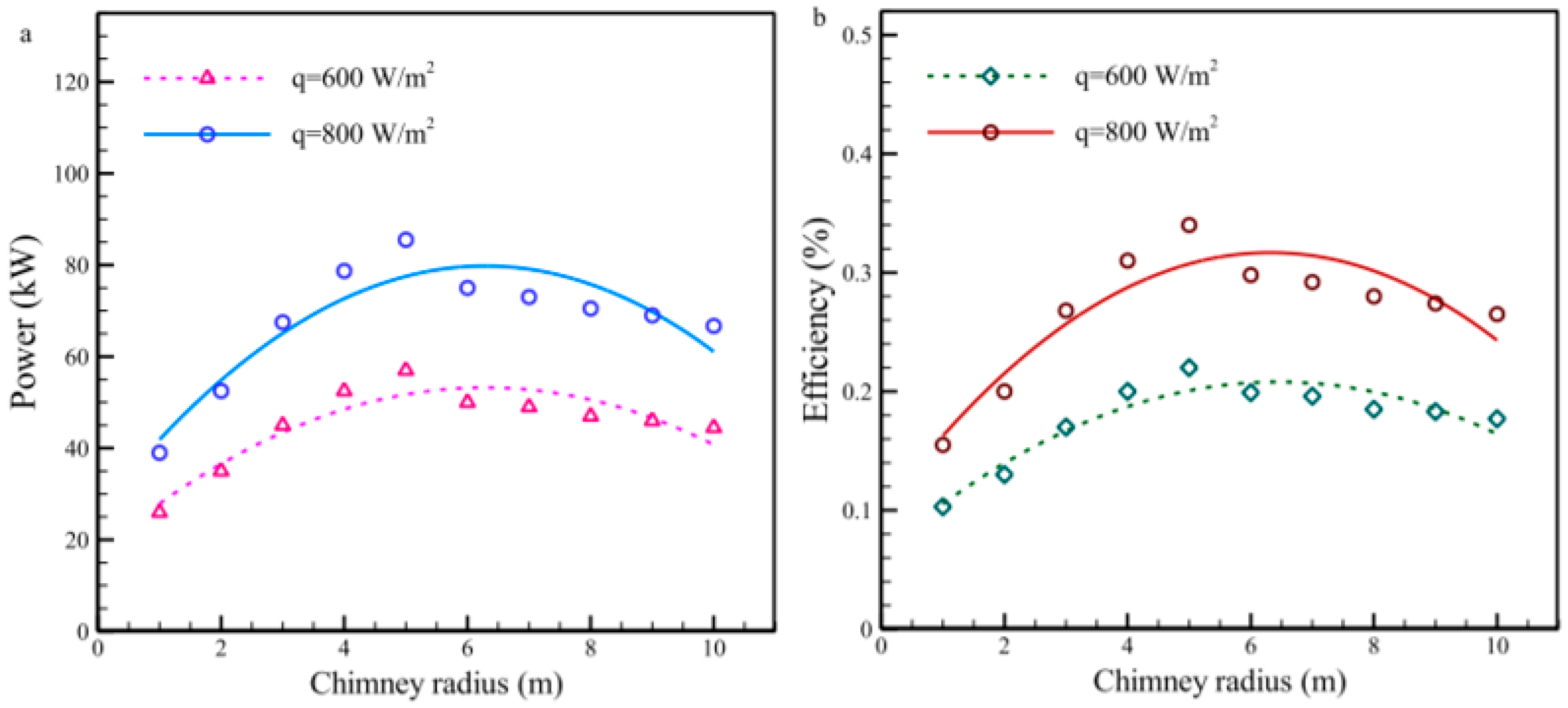
35] examined the chimney’s diameter’s impact on solar chimneys’ power output with numerical analysis, and argued that increasing the chimney diameter would not affect the system’s power output and efficiency after a certain point. The research stated that the system, which gives a 10.1 MW power output with a 20-m chimney diameter, would provide 13 MW power output by increasing by 28.7% when the chimney diameter was set to 60 m. Toghraie et al. [
91] showed the impact of the chimney diameter of the model they designed with the finite element method on the system’s power output and efficiency. They stated that the maximum power output and efficiency peaked at a certain point, and increasing the chimney diameter after this point had a negative effect on the system, and a similar effect was also seen on the system’s mass flow and pressure as shown in
Figure 29.
Gholamalizadeh and Mansouri [
81] claimed that by increasing the chimney diameter from 3 m to 5 m with the CFD model of the Iran solar chimney, Kerman, the mass flow rate of the system could increase up to 150%.
5.6. Convergent and Divergent Chimney Design
The design parameters affect the performance of solar chimney power plants as much as the geometric parameters. This situation was understood from the slope of the collector. Similarly, the chimney design affects the performance of the system. The chimney diameter not being fixed causes effects on the system’s performance, as this affects the airflow. This is clear in different studies as shown in
Figure 30,
Figure 31,
Figure 32,
Figure 33,
Figure 34,
Figure 35,
Figure 36,
Figure 37 and
Figure 38.
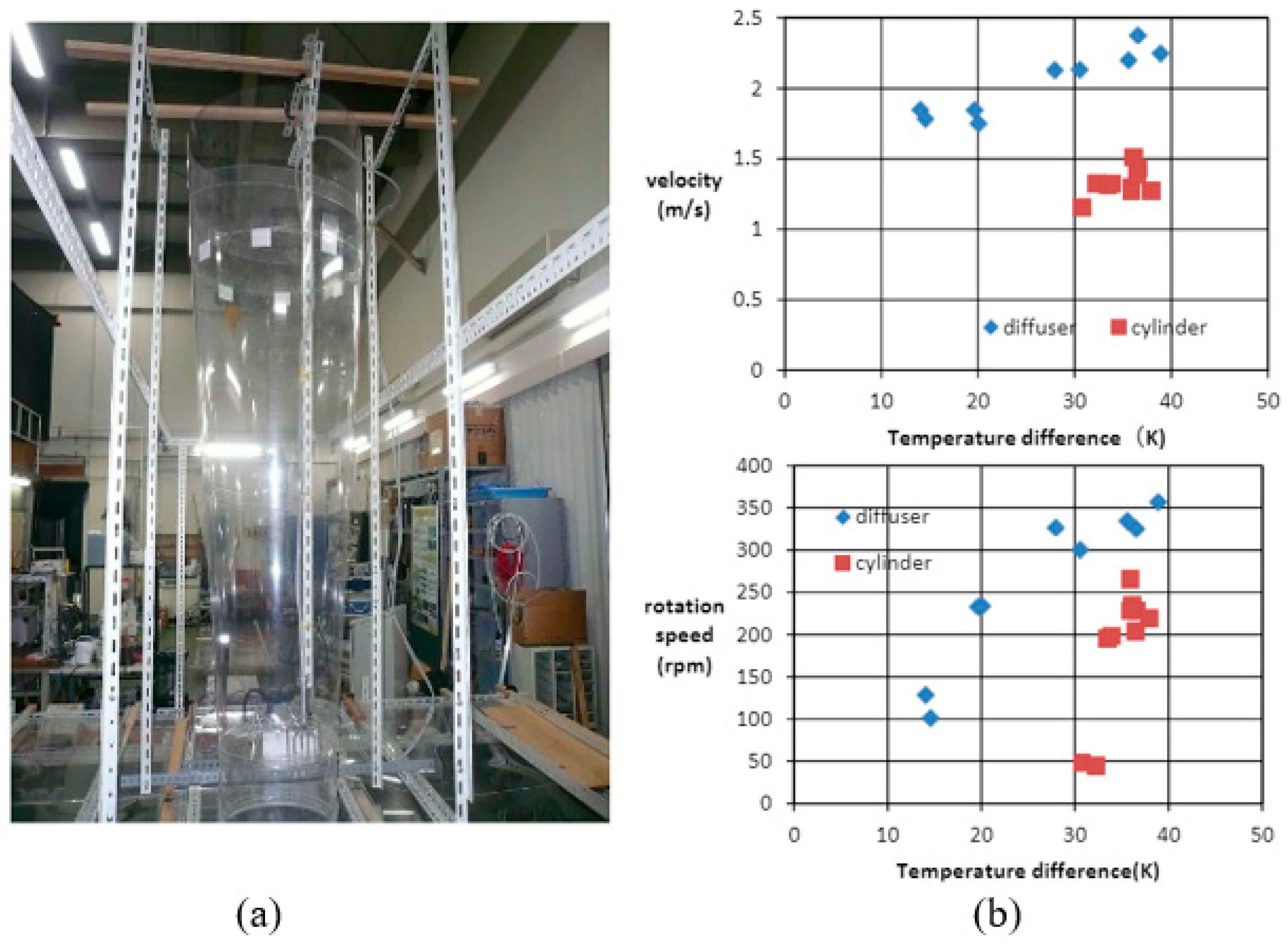
Motoyama et al. [
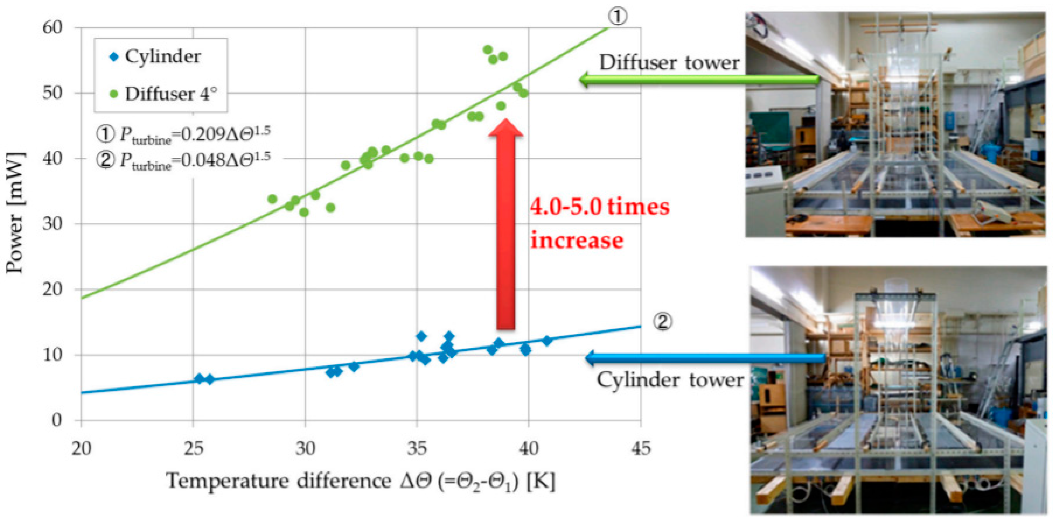
11] conducted an experimental design in a laboratory environment. They claimed that the divergent flue air velocity would be 50% higher than the cylindrical chimney design under the same conditions, and the rotation speed would likewise be 44.4% higher. Ohya et al. [
70] experimentally showed that the divergent chimney structure’s power output was 4–5 times more than that in the cylinder chimney structure under the same conditions. When they compared the chimney angle outputs for 2, 4 and 6 degrees, they emphasized that the highest power output and airflow velocity were in the 4-degree chimney design.
Nasroui et al. [
68] compared the outputs of the exponential divergent chimney models with the cylindrical chimney model using the computational fluid dynamics method with the developed model based on a small-scale solar chimney model. When the temperature, pressure and velocity distributions of the divergent chimney design were examined compared to the cylindrical model, they showed that the divergent design provided a better performance output.
Al-Kayiem and Al-Nakeeb [
96] examined the effect of divergent and convergent chimney design on the system according to a cylindrical chimney design using the Finite Difference Technique. They compared the hydrothermal efficiencies for all four seasons, and they claimed that the convergent chimney’s hydrothermal efficiency was two times that of the other designs.
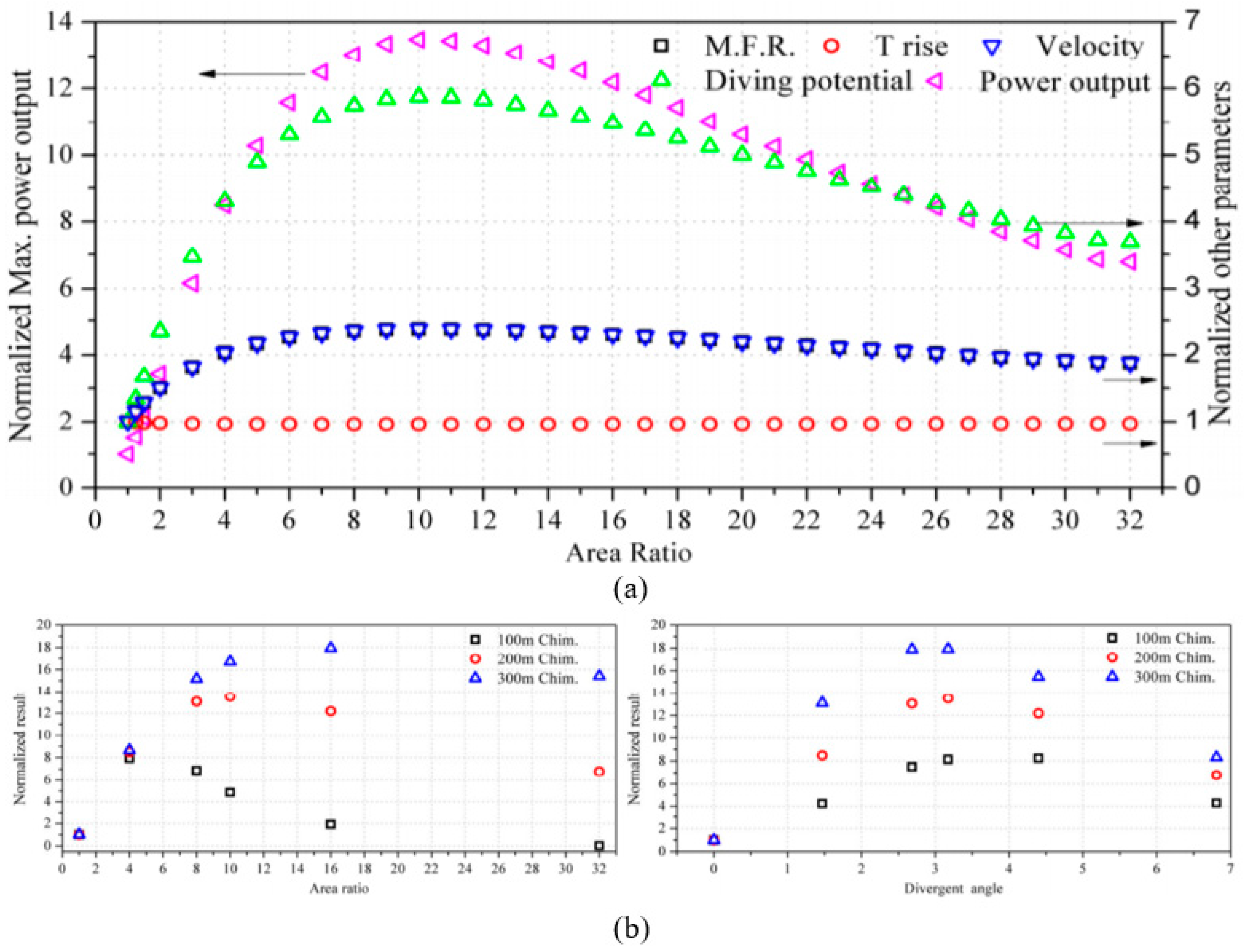
Hu et al. [
109] developed a CFD model and analyzed the effect of the change in the chimney exit area ratio to the chimney entrance area on solar chimneys’ performance. They explored the system’s effect on the airflow rate, temperature increase, diving potential, and power output by changing the chimney exit area between 1 and 32 times, taking the Manzanares pilot facility’s geometric dimensions as a reference, with the chimney entrance being constant. They claimed that an ideal value for the chimney exit area’s ratio (AR) to the chimney entrance area for the pilot plant was about 10. They claimed that the performance of the system at this value was the maximum. Similarly, for 100-m, 200-m and 300-m chimney heights, they provided a normalized result comparing the AR and the divergent flue angle. They emphasized that increasing the AR after this point, where it is the current peak in every situation, would have a negative effect on the system.
Hassan et al. [
100] investigated the effect of the divergent flue angle on the system by measuring the Manzanares pilot plant numerically. They claimed that if the system’s divergent flue angle, which gives 34 kW power output with a cylindrical flue in the reference case, is set to 1 degree, the power output would increase by approximately 100%. They argued that if the chimney angle was set to 2 degrees, the power output would be 65 kW; if it was set to 3 degrees, it would be 59 kW, which is the peak point for 1-degree power output. Ahirwar and Sharma [
101] claimed that the maximum power output with an inclined collector would be in a 190-m chimney based on the Manzanares pilot plant’s dimensions. They stated that increasing the chimney inclination angle at a 190-m chimney height would increase the system’s power. They emphasized that if the power output’s divergent chimney angle, which is 37.08 kW in the non-inclined condition, is set to 6 degrees, the power output would increase by 95% to 72.33 kW. Pattanashetti and Madhukeshwara [
110] analyzed a solar chimney with a radius of 100 m and a chimney height of 100 m using a 1-degree isometric CFD model. They fixed the chimney inlet diameter at 4 m and made performance comparisons for different area ratios by proportioning the chimney exit area to the chimney entrance area for values varying between 2.83- and 16-m chimney outlet diameters. They showed that for an area ratio (AR) of 9, the system gave the maximum performance, and higher AR values had a negative effect on the system. They claimed that up to 100 times more kinetic energy could be obtained with different designs at 800 W/m
2 radiation intensity. Ghorbani et al. [
111] designed a hybrid dry cooling tower with a height of 200 m and a collector radius of 100 m in a solar chimney format. They claimed that the system with a diverging flue angle of 1.5 degrees in the chimney design would increase the air velocity on the radiators from 5.65 m/s to 6 m/s, which is an increase of 6.2% compared to the non-inclined chimney.
Das and Candramohan [
112] designed small-scale solar chimney models with heights of 7 m and 3.5 m using a 3D computational model. They evaluated the performance of the CFD model in different chimney structures. They showed that the maximum power output and airflow velocity would be achieved with a 2-degree divergent chimney design. In this respect, the design with large angles would negatively affect the system’s performance. In CFD studies based on the Manzanares pilot plant’s geometric dimensions, Xu and Zhou [
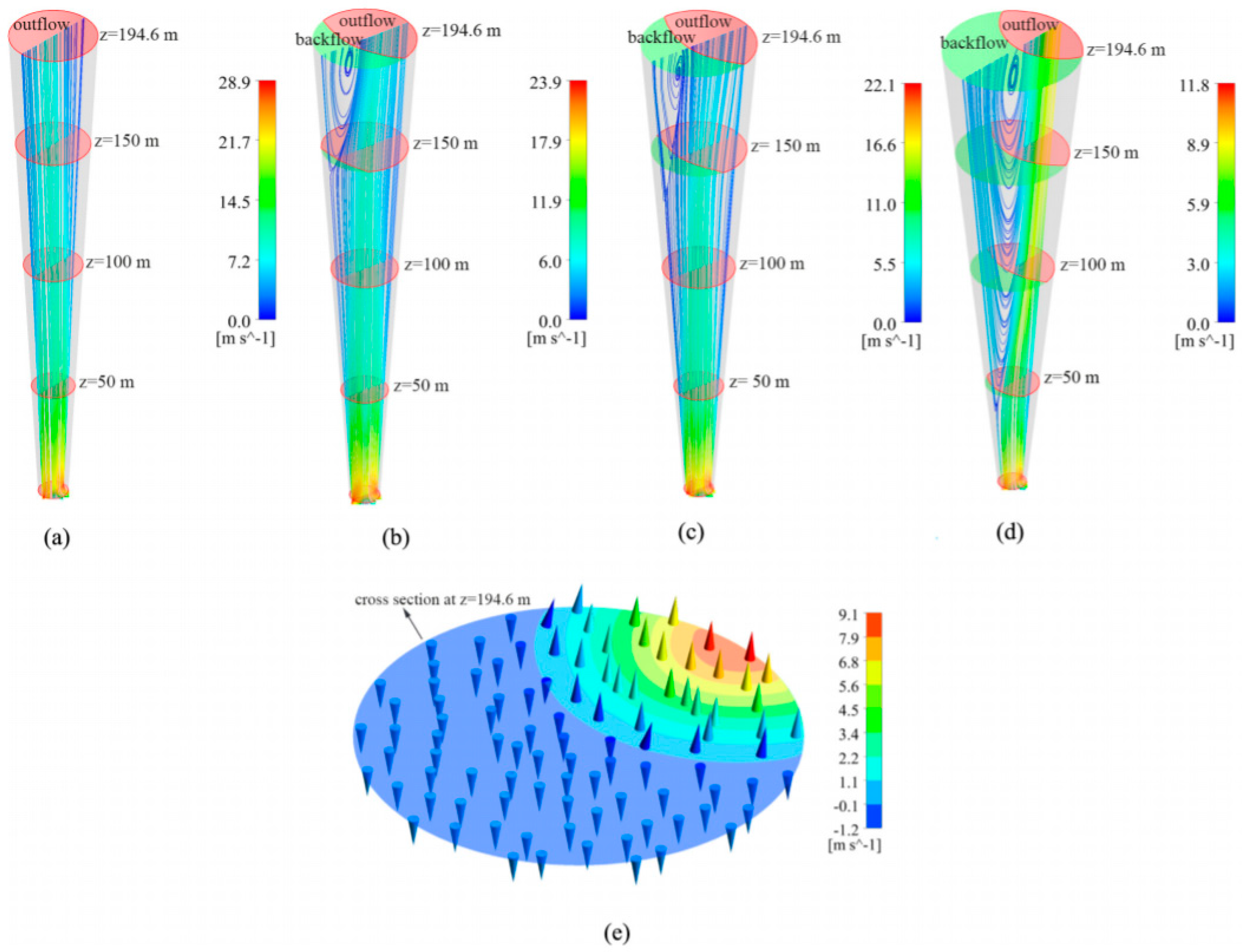
113] analyzed the effect of a divergent flue angle on the system by increasing the chimney outlet diameter to keeping the chimney inlet diameter constant. They determined the power output and airflow rate by matching the chimney exit area ratio to the chimney entrance area (COAR) with the divergent flue angle. They conducted a CFD study involving the total pressure potential (TPP), which consists in the working method, buoyancy and static pressure recovery using the effective pressure potential recovery coefficient (EPPRC). They claim that the maximum performance data would be obtained when the COAR is 8.7. They emphasized that when the area ratio is 8.7, the power output would increase 10.9 times to 231.7 kW compared to the reference situation. They stated that COAR values greater than 8.7 cause a reverse flow in the chimney, which would reduce the power output and airflow velocity, which adversely affects the system. Koonsrisuk and Chitsomboon [
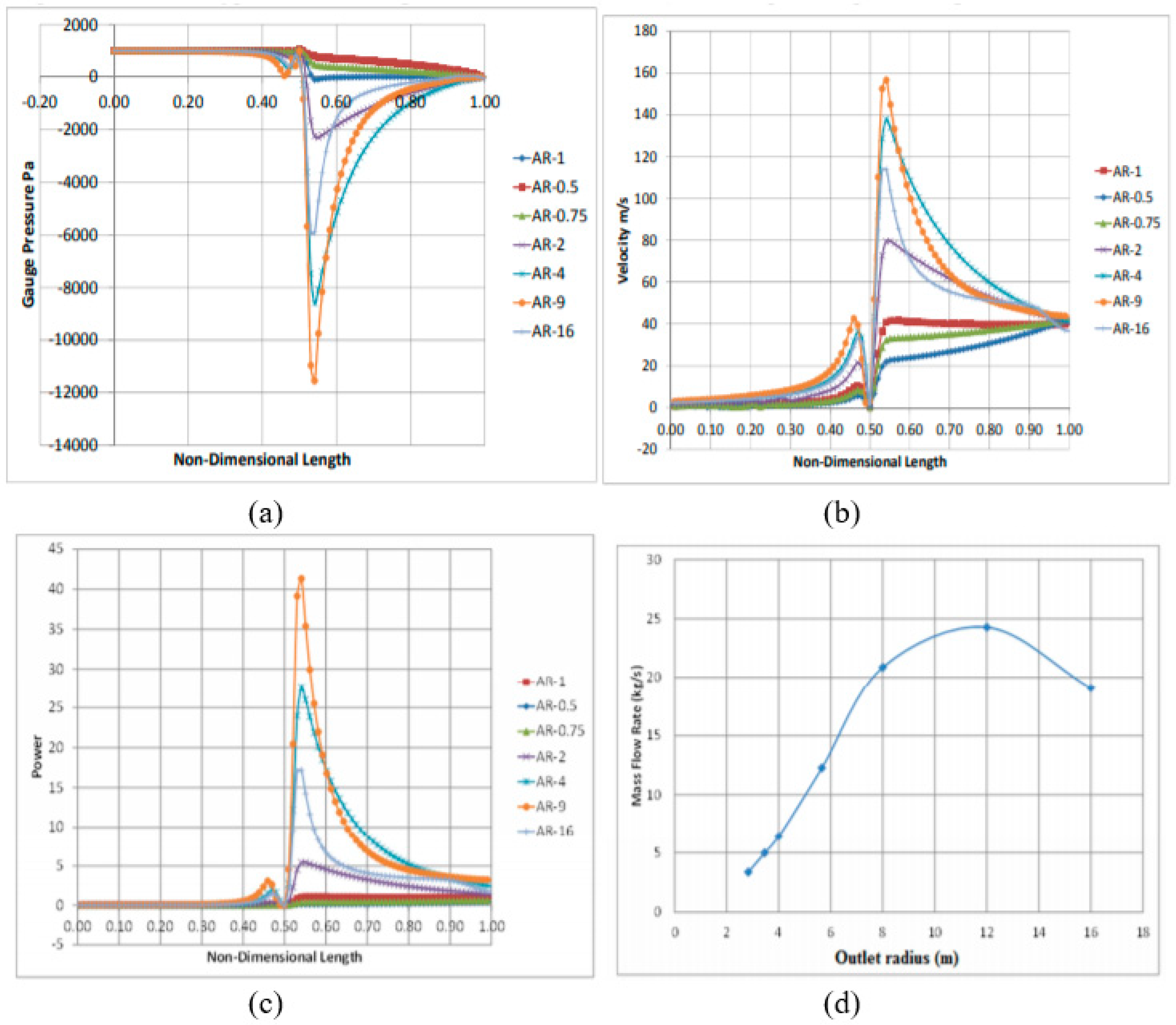
114] designed a solar chimney model with a 100-m high chimney, a 100-m radius and a collector 2 m above the ground, using computational fluids. They fixed the chimney inlet diameter to 4 m, and they performed simulations in different situations by proportioning the chimney exit area to the chimney entrance area (AR) for values ranging from 2.83 m to 16 m for the chimney exit radius. When they compared the results obtained from the 5-degree axial symmetric CFD model, they claimed that when the AR value was 16, the system’s power output would increase to 94.29 times that given in the reference situation efficiency system, which would reach 25%.
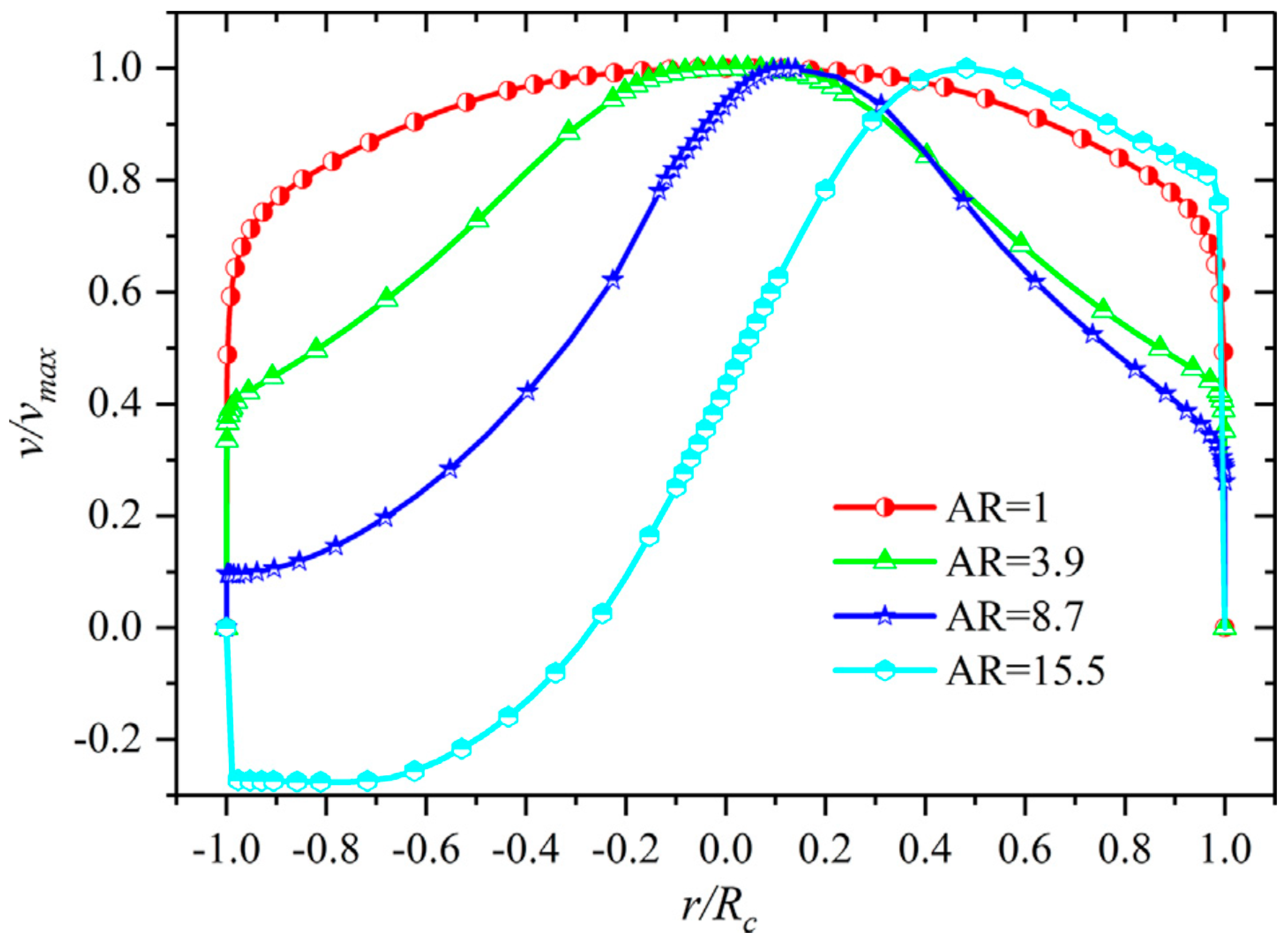
Figure 37.
EPPRCs of different cases and the distribution of the axial velocity along the specified diameter of the chimney cross-section at a height of 190 m for different COARs [
113]. (Adapted with permission from ref. [
113]. Copyright 2018 Elsevier.)
Figure 37.
EPPRCs of different cases and the distribution of the axial velocity along the specified diameter of the chimney cross-section at a height of 190 m for different COARs [
113]. (Adapted with permission from ref. [
113]. Copyright 2018 Elsevier.)
Figure 38.
Streamlines of a divergent chimney for different COARs of (
a) 8.7, (
b) 11.9, (
c) 15.5 and (
d) 24.2, and (
e) velocity vectors of the chimney outlet (COAR = 24.2) [
113]. (Adapted with permission from ref. [
113]. Copyright 2018 Elsevier.)
Figure 38.
Streamlines of a divergent chimney for different COARs of (
a) 8.7, (
b) 11.9, (
c) 15.5 and (
d) 24.2, and (
e) velocity vectors of the chimney outlet (COAR = 24.2) [
113]. (Adapted with permission from ref. [
113]. Copyright 2018 Elsevier.)


 ,
, 


