Long High-Performance Sustainable Bolt Technology for the Deep Coal Roadway Roof: A Case Study
by
 , , and
Houqiang Yang
1, 
Changliang Han
1,*,
Nong Zhang
1,
Yuantian Sun
1,
Dongjiang Pan
2 and
Changlun Sun
1 1
Key Laboratory of Deep Coal Resource Mining, Ministry of Education of China, School of Mines, China University of Mining and Technology, Xuzhou 221116, China
2
State Key Laboratory of Shield Machine and Boring Technology, China Railway Tunnel Group Co., Ltd., Zhengzhou 450001, China
*
Author to whom correspondence should be addressed.
Sustainability 2020, 12(4), 1375; https://doi.org/10.3390/su12041375
Submission received: 15 January 2020
/
Revised: 5 February 2020
/
Accepted: 11 February 2020
/
Published: 13 February 2020
Abstract
:High-efficiency maintenance and control of the deep coal roadway roof stability is a reliable guarantee for safe production and sustainable development of a coal mine. With belt haulage roadway 3108 in MenKeqing coal mine as the research background, in situ investigation, theoretical analysis, numerical simulation, and engineering practice were carried out to reveal the law of improving the bearing state of bolts by increasing the thickness of the roof anchoring layer. Also, the mechanism of the high-efficiency and long anchoring of the roof is revealed. Results show that increasing thickness of the roof anchorage layer could mobilize deep rock mass to participate in the bearing and promote the bolt to increase the resistance in a timely manner to limit the deformation of rock mass. Through the close link between shallow soft rock mass and deep stable rock mass, the deformation of the shallow rock mass is well controlled and so are the development and expansion of the roof separated fissures from shallow to deep. Long high-performance sustainable bolt technology for roof are proposed and carried out to control the stability of the deep roadway roof. Engineering practice indicates that deformations of roof could be efficiently controlled. The maximum deformations of the roof and sidewall-to-sidewall are 17 mm and 24 mm, respectively. No obvious separation fissures are found in the anchoring range of roof. This study provides a reference for roof stability control of deep roadway under similar conditions.
1. Introduction
Coal resources play a supporting role in China’s economic development. With the gradual exploitation of shallow resources [1,2,3], the exploitation of deep buried resources has become an inevitable trend in China’s coal mining. At present, the mining depth is decreasing at the rate of 10–25 m per year [4]. To solve the problem of deep mining is to consider the future of coal mining. The problem of deep buried and high stress roadway support is one of the major technical problems in deep mining [5,6]. Under the action of deep buried high stress, the difficulties faced by roadway support increase sharply [7]. Roof safety control is the most important part of the roadway surrounding rock control. As there is a contradiction between the gradual increase of mining depth and the more difficult support of deep roadway, the solution of roof efficient safety control has become a key technical problem which restricts the efficient mining of coal. Therefore, studying the high-efficiency and safe maintenance control of roadway roof under the condition of deep burial is of great significance for the high-efficiency and safe production and sustainable development of a coal mine [8,9,10].
In view of the deformation characteristics and control measures of the roadway roof under the condition of deep burial, a lot of research has been carried out. Wang [11,12] studied the influence of support resistance on the deformation of the deep high stress roadway roof and revealed the mechanical nature of its deformation that is difficult to control. Wang thus proposed the principle that the supporting structure should meet the coordination of large deformation of roof. Xie [13,14] discussed the mechanical characteristics and energy dissipation law of different high ratio coal rock structure from the perspective of energy release and dissipation and put forward two roof support principles, successfully applying this to the test roadway. Qin [15] used the method of theoretical analysis and numerical simulation to systematically study the distribution characteristics of the roof bearing structure of the deep soft rock roadway and finally proposed and successfully applied the roof reinforcement scheme of the deep dynamic soft rock roadway. Li [16] analyzed the strain-softening behavior, damage, and heterogeneity of rock masses of the deep roadway, established the strain-softening model of heterogeneous jointed rock mass considering the statistical damage, and successfully applied the model to the engineering practice. Through numerical simulation and similar material test, Qi [17] studied the influence of roof presplitting and rock mass filling on the stability of roadway surrounding rock of deep high stress roadway. Guo [18] used the pressure arching theory and numerical simulation method to study the deformation and instability mechanism of a large-span complex roof under deep-buried condition, designed and successfully applied the support scheme of “anchor (cable) + metal mesh + M-strip + single-prop”. Zhang [19] established the mechanical structure model of the surrounding rock of the deep three soft coal seam roadway, revealed the deformation mechanism of the roadway roof and proposed the principles for the SRDC of this asymmetrical roadway in deep TCS. Liu [20] studied the roof impact damage characteristics in the process of driving deep full coal roadway in Northwest coal field, obtained the induced factors of roof impact, creatively proposed and successfully applied the four-step scheme of roof impact prevention and control of deep full coal roadway. In view of the control problem of the surrounding rock of the large section chamber under the 1200 m deep goaf, Xie [21] proposed a comprehensive control technology using the strong anchor bolt (cable) support, the pouring of a thick reinforced concrete wall, and a full section pressure-regulating grouting behind the wall. Tian [22] analyzed the roof structure near the driving face of a coal roadway through mechanical analysis and numerical simulation, revealed the mechanism of induced disasters. The results showed that the artificial support structure and C-shaped bracing structure co-determine the safety of the roof.
At present, exploitation is carried out more often under conditions of large rock mass deformation, for which bolt flexibility indexes should be determined [23] or rock bolts with increased strength parameters should be used [24]. Most of the above research focused on the deformation and failure mechanism of roadway roof and comprehensive control measures, which have achieved preliminary research results. In actuality, there is still a lack of research on increasing the thickness of roof anchorage layer to mobilize the deep surrounding rock to participate in the load and improve the load state of the anchor to suppress roof deformation. In order to achieve a more efficient and safe control of the deep roadway roof, in situ investigation, theoretical analysis, numerical simulation and industrial test were carried out to study the influence law of increasing the thickness of the roof anchorage layer on the bearing state of the bolt. We proposed a new control technology of a long high-performance sustainable bolt and the roof control effect was satisfactory. This study provides a reference for roof stability control of deep roadway under similar conditions.
2. Engineering Geological Conditions
2.1. Roadway Location and Lithology of Roof, Floor
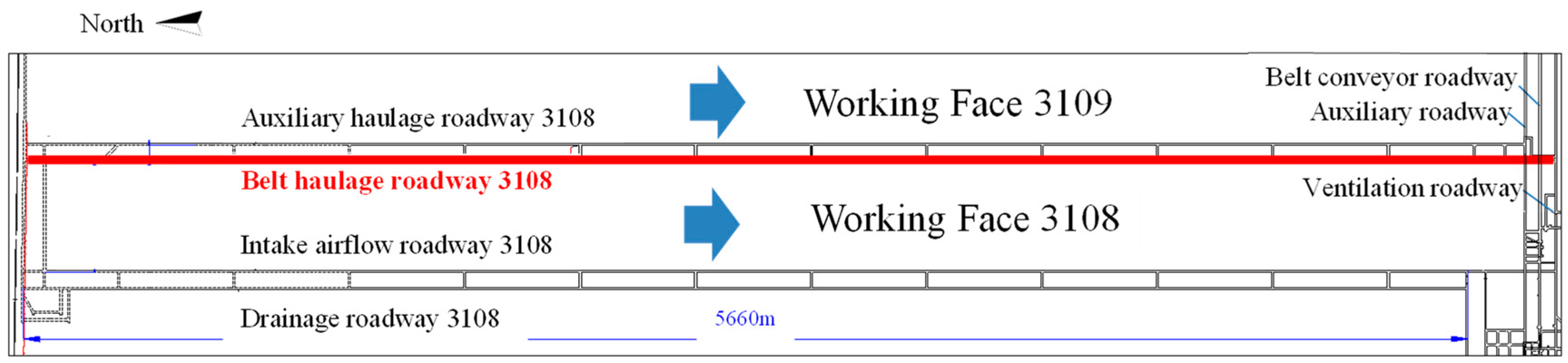
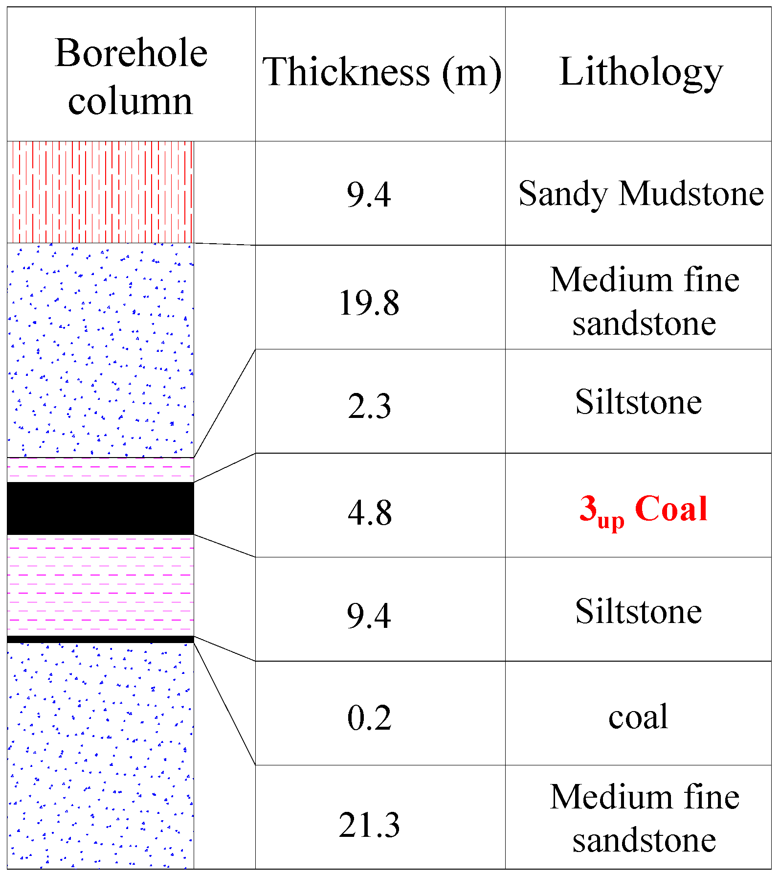
Menkeqing coal mine is located in Ordos City, Inner Mongolia Province, China, with a design production capacity of 12 million tons per year. It is a typical deep-buried mine, which is mainly mined in the 3up coal seam with an average buried depth of 723 m. The belt haulage roadway 3108 (Figure 1) of the test roadway is driven along the 3up coal seam floor, and there is no mining influence around during the excavation. The design width of the roadway is 5.4 m, the height is 3.6 m, and the total length is 5660 m. In the roadway excavating process, there is a full coal roadway with an average coal thickness of 3.34 m. The coal seam is simple in structure and stable in horizon. The immediate roof is siltstone with an average thickness of 2.26 m, the main roof is medium sandstone with an average thickness of 19.79 m, and the main floor is medium sandstone with an average thickness of 21.24 m. The concrete occurrence of the roof and floor strata is shown in Figure 2.
2.2. Original Support Scheme and Maintenance Effect
2.2.1. Original Support Scheme
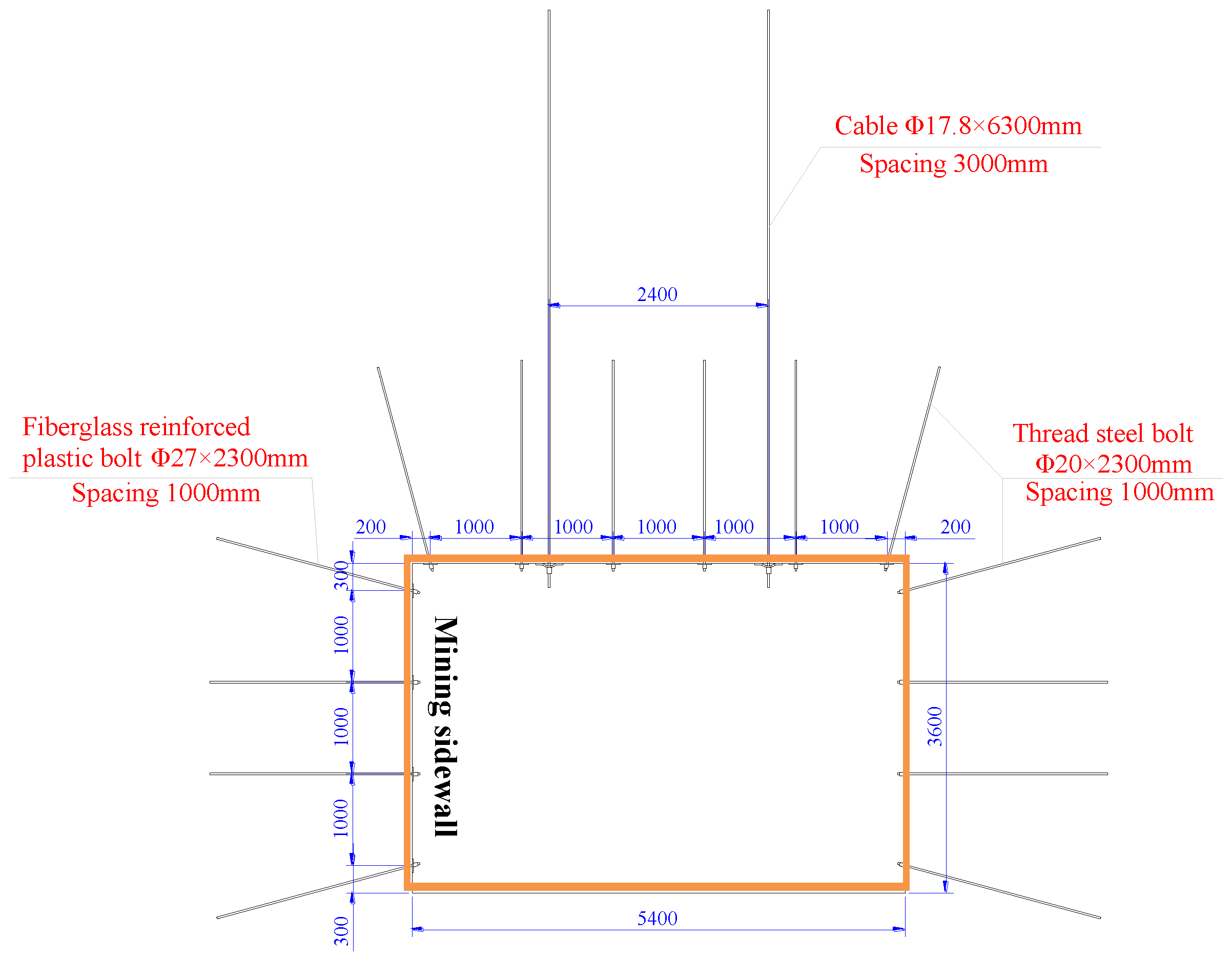
As shown in Figure 3, the roof of belt haulage roadway 3108 was supported by bolt + cable at the initial stage of excavating. The roof was supported by six Φ 20 × 2200 mm left-hand threaded steel bolts. The bolts in the left wing and right wing had an indentation of 15° and the rest were installed vertically. Each bolt was anchored by one MSCK 2370 mm resin cartridge and the pretension of bolt was 50 kN. In addition, two Φ 17.8 × 6300 mm cables were arranged for two rows of anchor bolts in each interval as the reinforcement support. All the cables were installed vertically on the roof of the roadway. Each cable was anchored with two MSCK 2370 mm resin cartridge, with pretension of 150 kN. The mixing time and setting time of resin cartridge are 8–15 s and 8–40 s, respectively. The inter-row spacing of the bolts and anchor cables is 1000 × 1000 mm and 1500 × 3000 mm, respectively.
2.2.2. Maintenance Effect of Roadway Roof
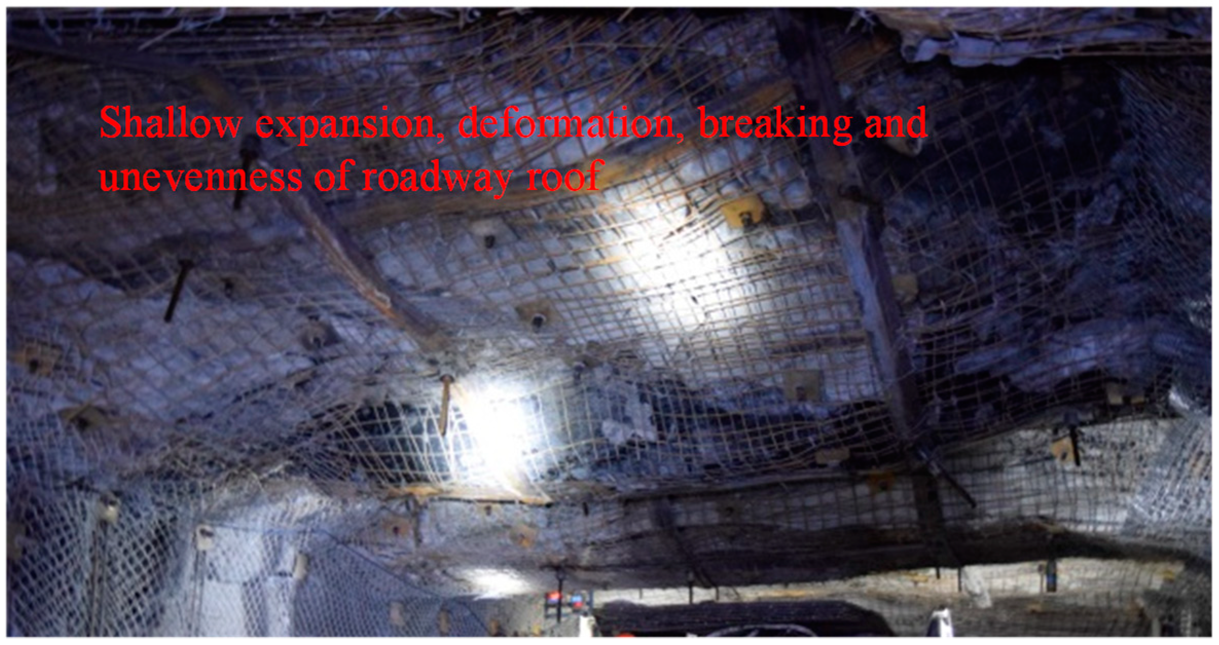
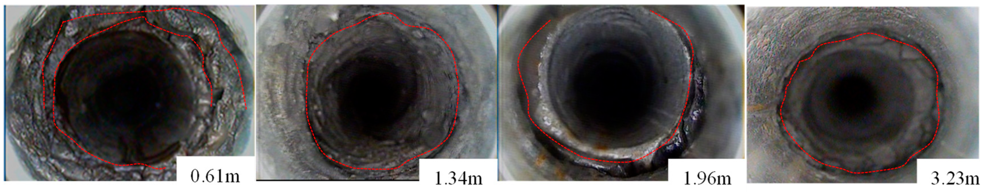
During the excavation stage of belt haulage roadway 3108, there was no influence of mining and excavation around. After the deformation was stable, the surrounding rock at the shallow part of the roof was loose and deformed, resulting in uneven surface of roof (Figure 4). According to the peeping results monitored using a ZKXG30 borehole scanner, there were transverse separated fissures with different development degrees in the depth of 1–3.2 m of the roof (Figure 5).
2.2.3. Analysis of Existing Problems
(1) Separated fissures outside the anchorage zone
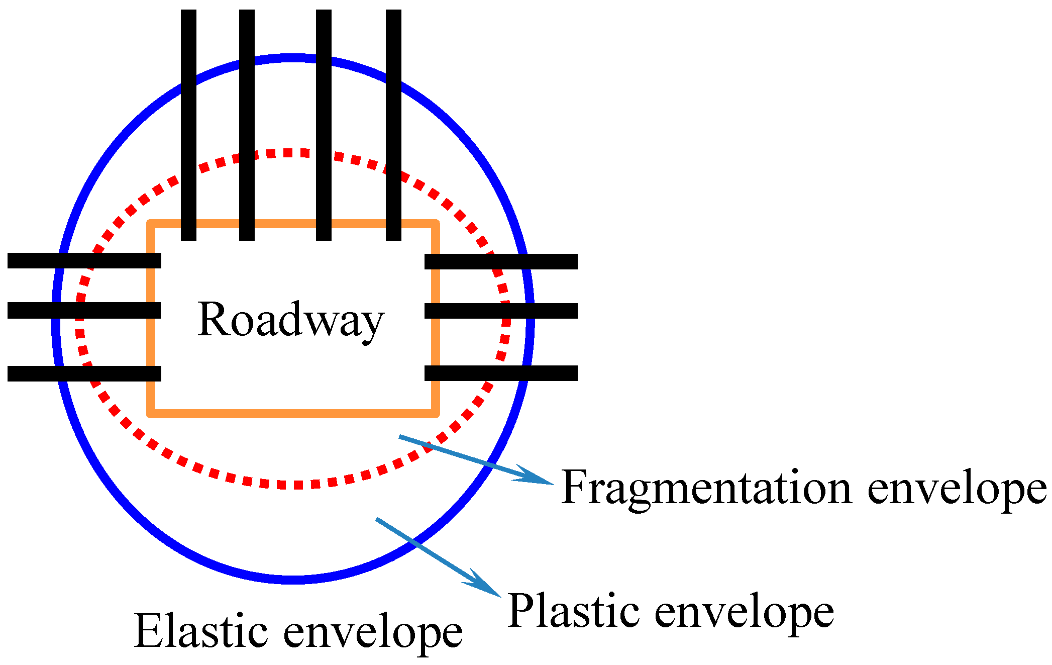
After the excavation of the roadway, the stress of surrounding rock is redistributed, and the stress concentration occurs in the local area, which shows obvious characteristics of circle layer distribution. The surrounding rock of the tunnel can be divided into three circles: fragmentation envelope, plastic envelope and elastic envelope. It has been proved that the deformation and failure of the fragmentation ring and plastic ring are the main reasons for the instability of the roadway [25,26]. As the result, these two rings often act as support objects of the roadway to limit its deformation. With the increase of mining depth, the fracture ring range of roadway increases gradually. According to Figure 5, there are still transverse separated fissures at the depth of 3.2 m of the roof. Given that the thickness of the foundation bearing circle formed by the 2.3 m bolt is less than the depth of the roof fracture ring, as a result, the end of bolt is anchored near the boundary of fracture ring. What is more, the 2.3 m bolt is so short that the whole bolt falls into a disturbance range, which leads to the looseness of itself. When the rings of fragmentation and plastic are deformed as a whole, the roof bolts become loose as a whole with the surrounding rock deformation. At this time, the displacement difference of the surrounding rock is very small within the anchor area of bolt, while the working resistance of the bolt rises slowly. As a result, the lower soft rock stratum is more likely to become loose and deform without restrict, and the separated fissures keep developing outside the anchor area. The separated fissures outside the anchor area are borne by the low-density cable, and it is difficult to inhibit separated fissures penetration development outside the anchoring range of the anchor cable. To be concluded, the separation is main reason for hindering the stress transfer of the support and causing mass looseness and collapse of the rock.
(2) Shallow expansion deformation of roadway roof
After the excavation of roadway, the stress transfer of surrounding rock is gradually adjusted under the coupling effect of the bearing damage of the rock mass, and finally forms a steady-state stress field. During the stress adjustment period, the damage of rock mass and decrease of energy storage lead to the existence of low value stress area in the shallow part of the roof. At this time, the insufficient thickness of the anchor layer (2.3 m) leads to a low working resistance of the anchor bolt, which fails to restrain the expansion and deformation from low stress area in the shallow part.
Thus, when the bolt length is insufficient, the rock mass deformation difference within the anchorage range of the bolt is small, which leads to the slow resistance increase of the bolt, so it is difficult to restrain the rock mass deformation in the shallow part of the roof and the whole anchorage range. Therefore, it is of great significance to study the influence of increasing the thickness of the roof anchorage layer on the bearing state of the bolt.
3. Control Law of High Efficiency and Long Anchorage of Roof
3.1. Setting Up the Numerical Model
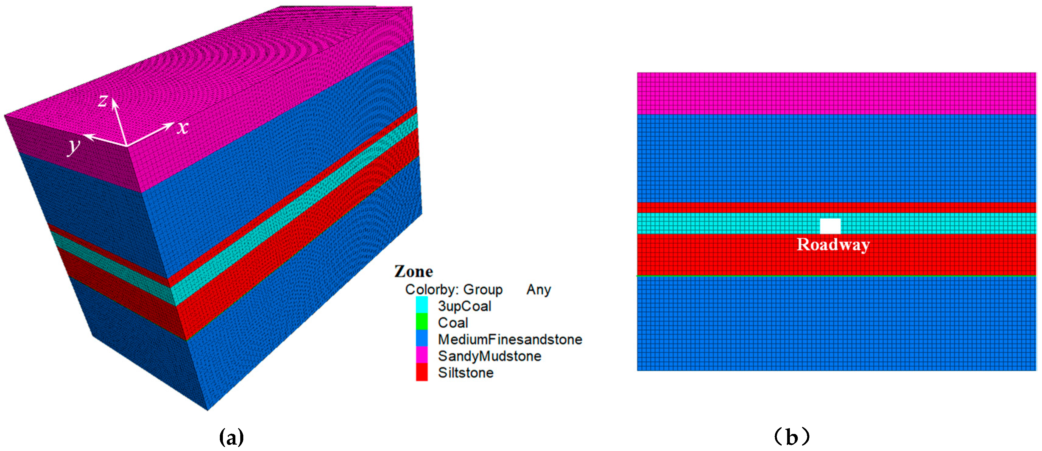
In order to simulate influence law of the thickness of different anchorage layers on the bearing state of the bolt, we establish the numerical model (Figure 6) using finite difference software FLAC3D according to the engineering geological conditions of the Menkeqing coal mine. The model length × width × height = 90 m × 50 m × 67 m, the width × height of roadway is 5.4 m × 3.6 m. The upper boundary load of the model is calculated according to the actual mining depth of 723 m and the upper end of the model is free to apply a vertical load of 18 MPa. The bottom boundary of the model is fixed vertically; both left and right boundaries are fixed horizontally without displacement. The model adopts the Mohr-Coulomb yield criterion. The physical parameters of rock strata are taken from the Menkeqing coal mine and the adjacent Hulusu coal mine of the same coal field [13,14]. The process of roadway excavation is realized by “Null” command after the model original rock stress calculation is stable.
3.2. Calculation Method and Results
3.2.1. Calculation Method
In order to study the influence law of increasing the thickness of the roof anchorage layer on the bearing state of the bolt, the axial force measuring point of the bolt is arranged at the free section of the roof bolt near the excavating face of roadway, and the radial displacement measuring points are arranged at the lower surface and the upper surface of the bearing structure (Figure 7), respectively. The main purpose is to monitor and collect the data of rock mass deformation difference and anchor resistance within the range of different thickness of anchor layer.
3.2.2. Calculation Results
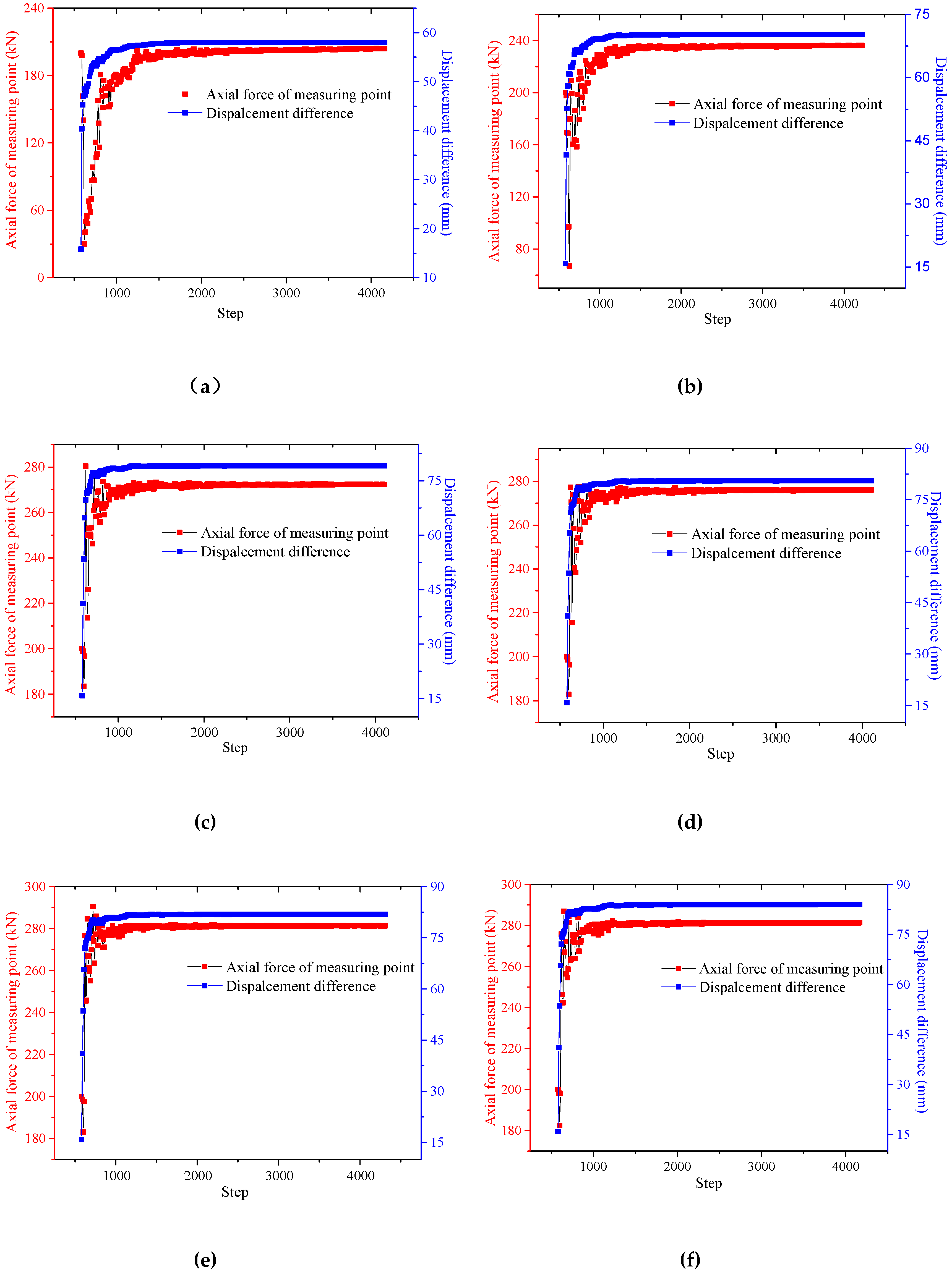
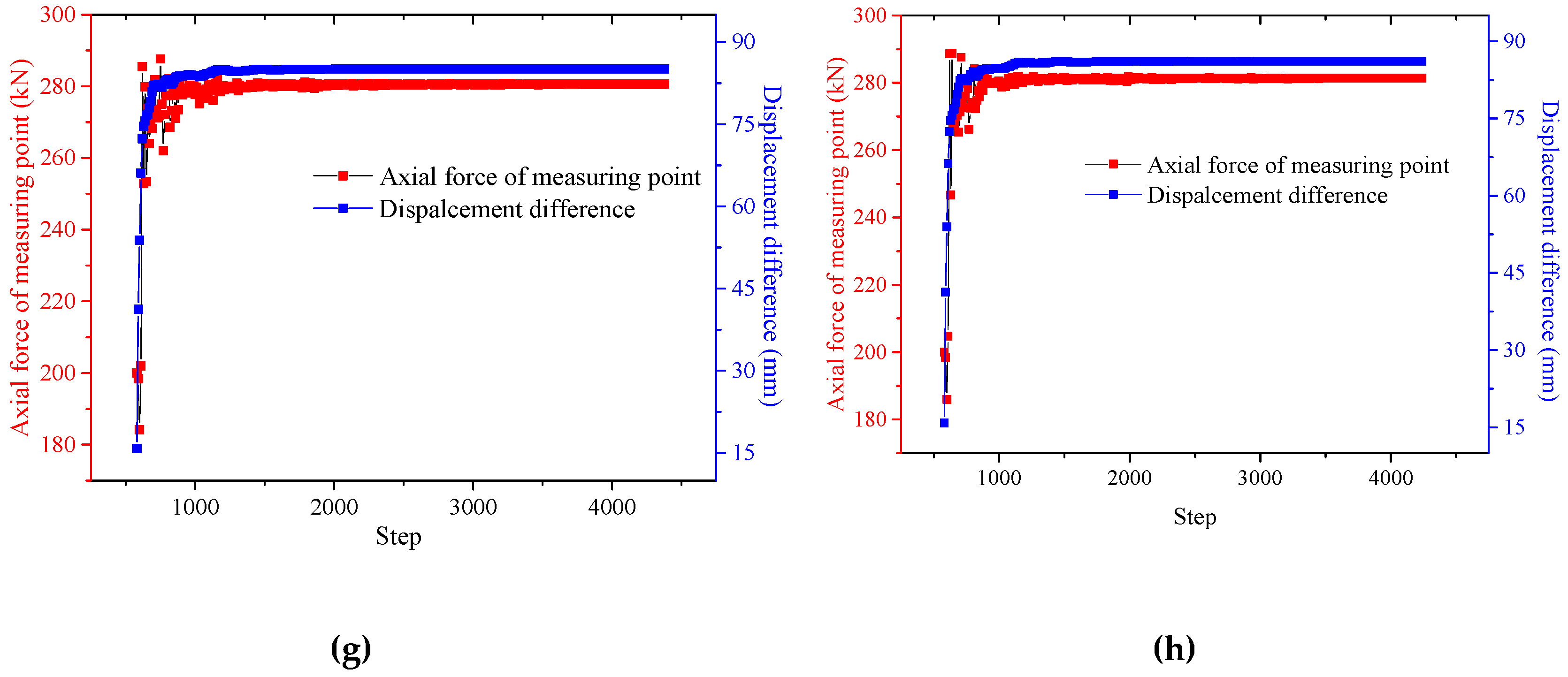
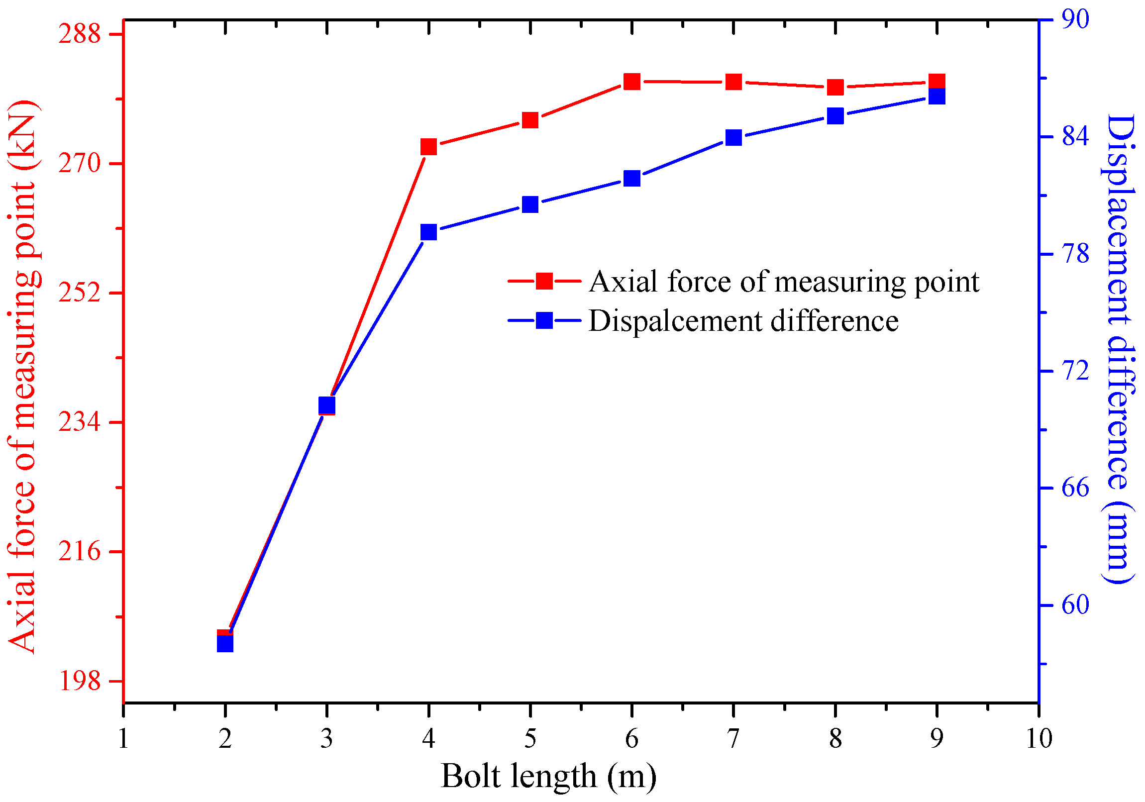
The axial force (f)—displacement difference (△u =d2 − d1)—time history curve of different measuring points is obtained as shown in Figure 8. After enough running steps, the axial force and displacement tend to become stable, and final data are shown in Figure 9.
With the length of the bolt on the roof increasing, the difference of the displacement of rock mass within the anchorage range increases accordingly (Figure 9). At this time, the axial force in free section of the bolt also increases step by step. This is mainly because with the increase of bolt length, the end of the bolt is anchored in the stable rock stratum gradually through the roof fissure circle layer, and the decrease of displacement of the rock mass at the end of the bolt leads to the increase of difference of the displacement within the anchorage range. Given that the working resistance of the bolt is determined by the difference of rock mass deformation within the anchorage range of the bolt, as a result, the working resistance of the bolt increases with the increase of bolt length. When the length of the bolt rises to a certain level, the difference of rock displacement within the anchorage range tends to become stable, and the working resistance of the bolt does not change accordingly. Therefore, increasing the thickness of the anchoring layer on roof is capable of mobilizing the deeper surrounding rock on roof to participate in the bearing, improving the bearing state of the anchor, and finally, inhibiting the expansion deformation in shallow part of the roof and the development of the deep separated fissures effectively.
4. Control Technology and Engineering Practice
4.1. Long High-Performance Sustainable Bolt Technology
According to the theoretical analysis and numerical simulation results, the long high-performance sustainable bolt technology for roof (Figure 10) is proposed. Increasing the thickness of the roof anchoring layer to the stable rock layer can fully mobilize the performance of the deep surrounding rock and promote the increase of the resistance of bolt to limit the rock deformation in time. The close connection between the shallow soft rock and the deep stable rock layer, contributes to better control of the deformation of shallow soft rock, with the linkage of large and small displacement [27]. Moreover, it can also eliminate the development of the separated fissures outside the traditional short bolt, which improves the stability of the roof greatly. In addition, increasing the strength and thickness of roof bearing ring is helpful to resist the disturbance of mining stress.
4.2. Support Scheme Design
According to the above analysis, the roof supporting scheme of belt haulage roadway 3108 is modified. Combined with the original supporting scheme, the maximum development degree of roof separated fissures is about 3.2 m, and the length of roof bolt in the new support scheme is finally determined to be 4 m. The specific support parameters were designed as follows.
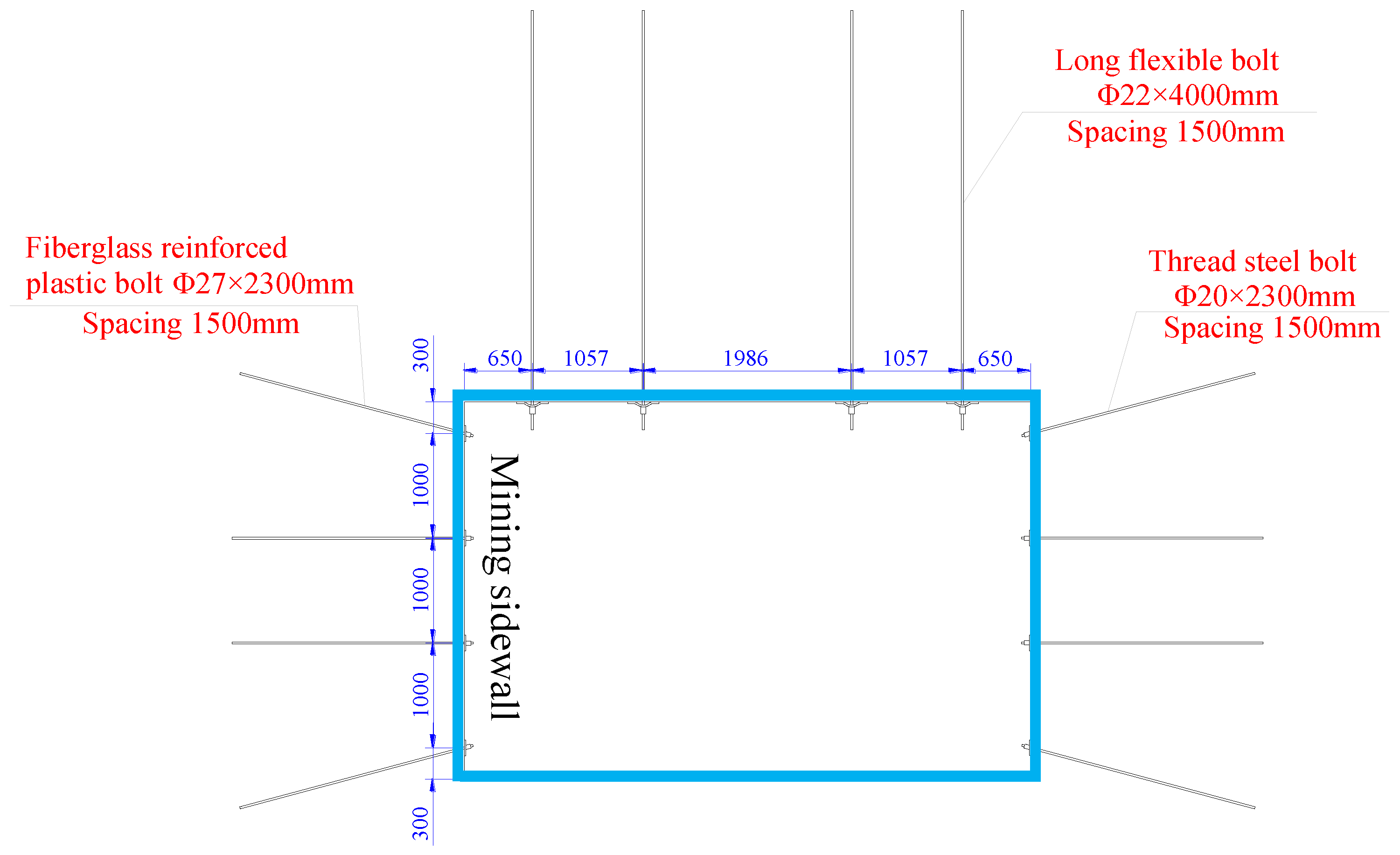
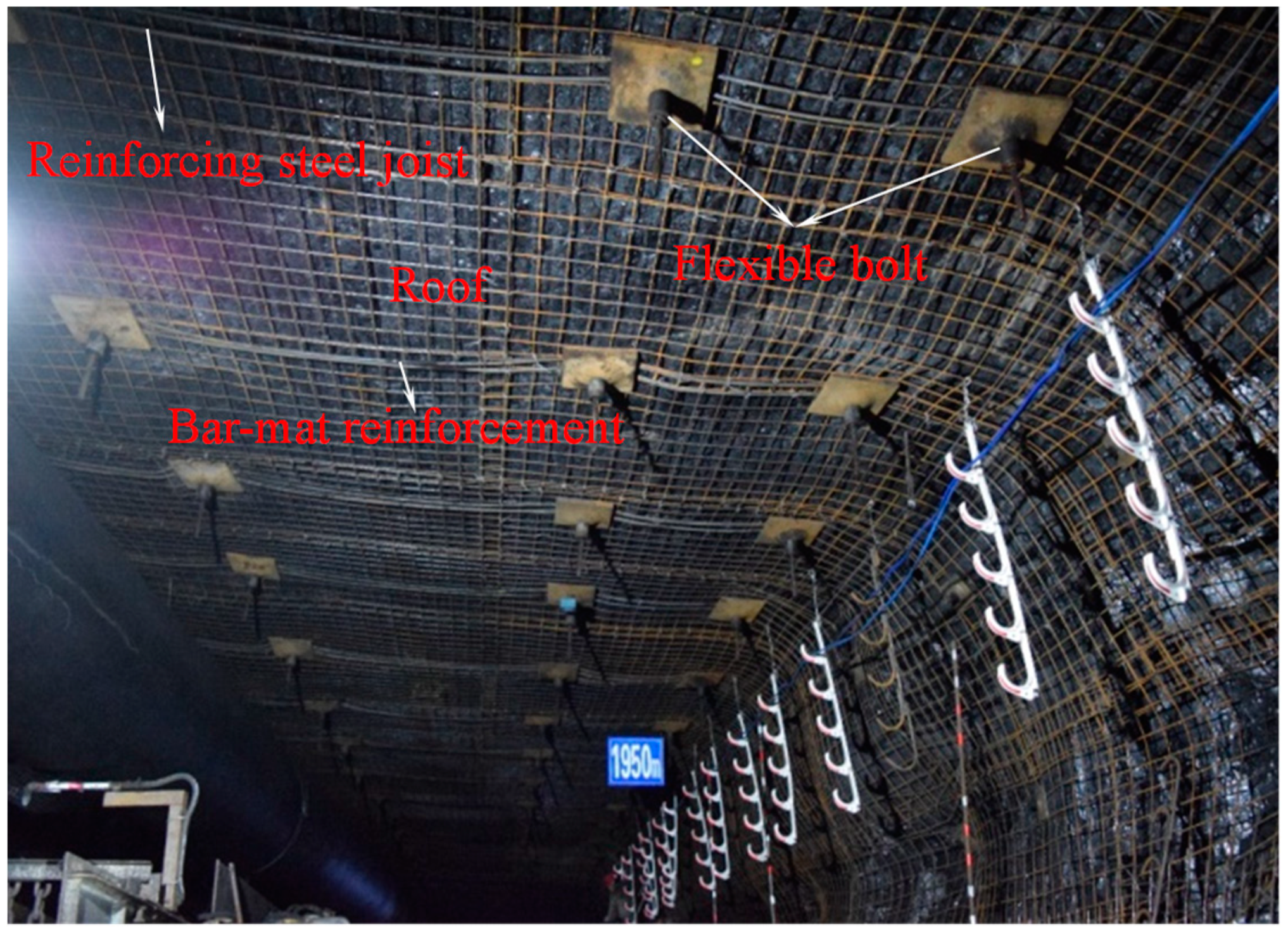
The cross section of the belt haulage roadway 3108 is rectangular with dimensions of 5.4 m in width and 3.6 m in height. As shown in Figure 11, the roadway roof is supported by four Φ22 × 4000 mm long flexible bolts, and bar-mat reinforcement for surface protection, reinforcing steel joist for diffusion of pretension. The row spacing of bolts is 1500 mm, and each row of four bolts is (1057, 1986, 1057) mm from the first to the fourth from the left. Each bolt is anchored with one CK2370 and one Z2370 resin cartridge. The pretension of the bolt is 200 kN. Road header with bolting machine (MB670) is used for excavating, the support is completed by the airborne drilling machine of MB670 at the same time of excavating, and the pretension of bolt is completed by the tensioning pump.
4.3. Supporting Effects Analysis
4.3.1. Monitoring of Roadway Surface Displacement
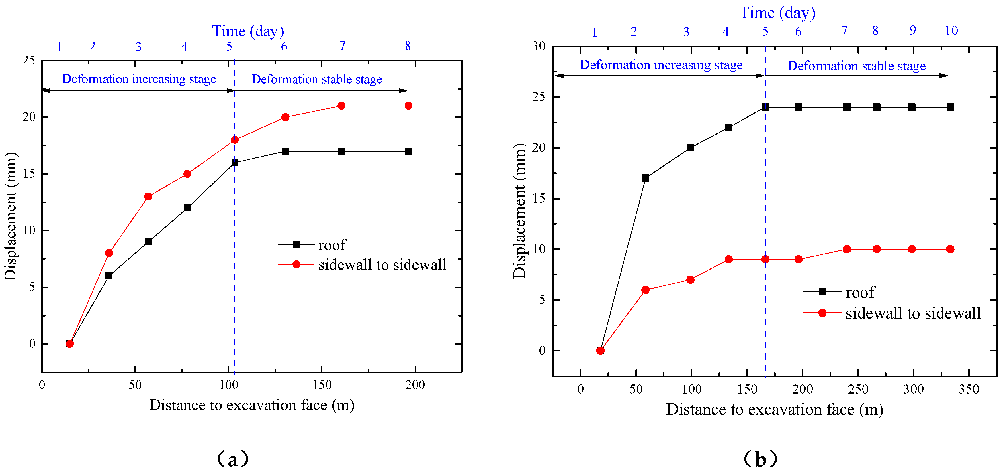
In order to figure out the deformation law of belt haulage roadway 3108 in the process of excavating, and to verify the feasibility of long high-performance sustainable bolt technology, we arrange roadway surface displacement monitoring station 1 and station 2 at the roadway mileage of 2720 m and 3100 m, respectively. Cross sectional measurement methods are adopted to monitor the deformation data of roof subsidence and convergence of the two sides of the roadway (Figure 12).
As shown from Figure 12, within 5 days after the arrangement of the monitoring station, the roof subsidence and two sides convergence increased rapidly, showing a linear growth trend, which is the disturbance stage of excavating. On the 6th day, with the continuous advance of the working face, the disturbance of excavation tended to be weak, and the deformation tended to be stable, gradually. Finally, the roof subsidence of station 1 became stable at 24 mm, and the convergence of two sides tended to be stable at 10 mm. The roof subsidence of station 2 became stable at 17 mm, and the convergence of two sides tended to be stable at 21 mm, which is a stable stage after excavation. In general, the deformation of the roof and the two sides has been significantly improved, and the surrounding rock has been effectively controlled. What is more, the roadway roof is relatively flat, and the support effect is well done (Figure 13).
4.3.2. Monitoring of Working Resistance of Bolt
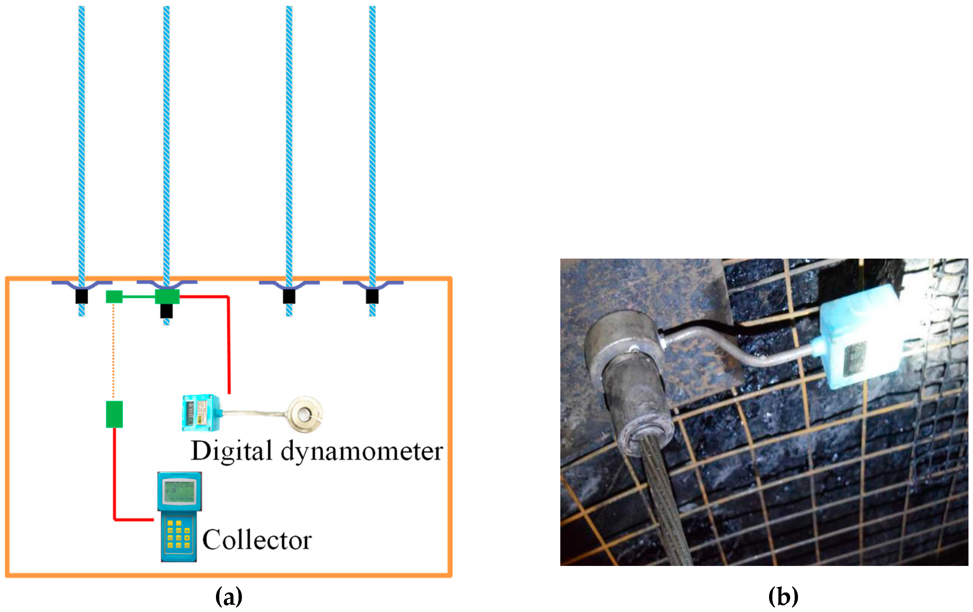
In order to study the influence law of the length of roof bolt on the working resistance of the bolt and verify the improvement effect of long high-performance sustainable bolt technology on the bearing state of the bolt, we arranged measuring stations #1, # 2 and # 3 respectively in the roadway mileage of 2720 m, 3100 m and 3500 m to monitor the working resistance of the bolt. The first step is to install MCS-400 mining intrinsic safety bolt Dynamometer on the second bolt on the left side of the roof and the Dynamometer records a group of the bolt working resistance data every two hours automatically. Then, to use its matching FCH2G/1 mining intrinsic safety hand-held Collector (Figure 14) to collect the data. The data composition is shown in Figure 15.
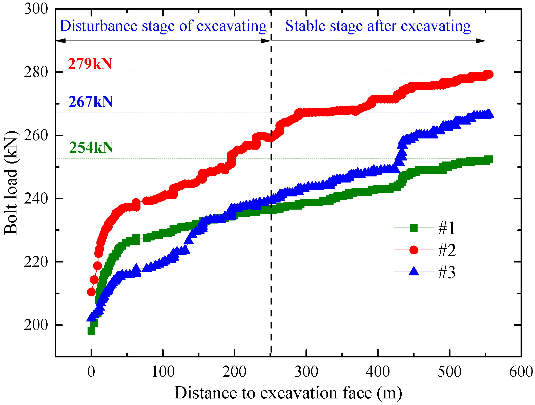
It can be seen from Figure 15 that the working resistance value of anchor increases rapidly within 250 m after the installation of three monitoring stations, which is mainly due to the adaption of the deformation caused by the redistribution of stress in roof rock mass. As the working face continues to move forward, the stress adjustment and deformation of the roof behind the working face tend to be stable, meanwhile, the growth of the working resistance of the bolt slows down and finally tends to be stable. The working resistance of the bolt measured by the Dynamometer at three stable stations is 254 kN, 267 kN and 279 kN respectively, which are significantly increased compared with the pretension (200 kN). The bearing state of the bolt is obviously improved and the results are consistent compared with the numerical simulation. The ideal results can be attributed to the increased length of the bolt which can make it anchor in the stable rock, and increase the deformation difference of rock within the anchorage range, so as to promote the bolt to increase resistance and restrain the rock deformation in a timely manner.
4.3.3. Monitoring of Roof Separated Fissures
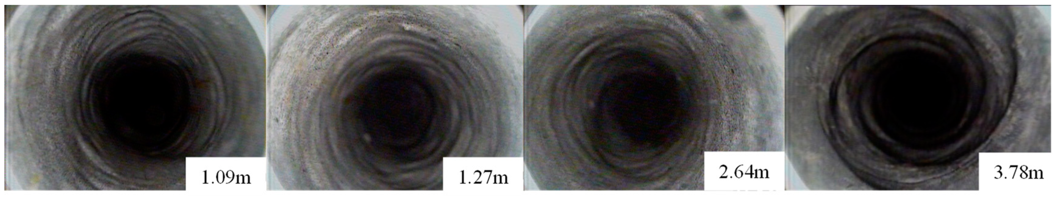
In order to figure out the development of roof separated fissures in belt haulage roadway 3108 under the condition of long high-performance sustainable bolt technology, the roof is peeped by the mining drilling peep instrument, and the peeping results is shown in Figure 16. It can be seen that no obvious separated fissures are found within the range of 1.09–3.78 m of the roof, and the roof control effect is well.
It can be concluded that increasing the length of roof bolt can make more roof rock participate in bearing. With the resistance of the bolt increase rapidly, the shallow soft rock mass on roof escapes from expansion and deformation effectively (Figure 13), which restrains the extension of the loosening scope going beyond the anchoring area that caused by the loosening failure of the shallow rock mass on roof. The close connection between the shallow soft rock mass and the deep stable rock layer inhibits the expansion and development of the roof separation from the shallow and deep. As a result, the rock mass and bolt get well promoted on simultaneous bearing, which makes the most of supporting efficiency of the bolt at the same time.
5. Conclusions
In this study, in situ investigation, theoretical analysis, numerical simulation, and engineering practice were carried out to reveal the control mechanism of high-efficiency and long anchoring in deep coal roadway roof. From these studies, the following conclusions are drawn:
(1) Based on the field investigation and theoretical analysis, the existing problems in the original supporting scheme of belt haulage roadway 3108 in Menkeqing coal mine are evaluated. It is considered to be the insufficient thickness of the foundation bearing ring on roof (the length of the bolt) that results in the shallow deformation on the roof along with the existence of the separated fissures inside and outside the anchorage range.
(2) After numerical simulation and theoretical analysis, the improvement mechanism of increasing the thickness of the roof anchorage layer under the bearing state of the bolt is researched. It reveals that increasing the length of the roof bolt and mobilizing the deep stable rock mass to participate in the bearing will increase the displacement difference of rock mass within the anchorage range, moreover, promoting the increase of the resistance of the bolt in time, which could improve the bearing state of the bolt and restrain the deformation of the rock mass.
(3) In view of the defects of the original support scheme and the theoretical analysis of the high-efficiency and long anchoring control on roof, this paper puts forward the long high-performance sustainable bolt technology for roof of the deep coal roadway, and carries out the corresponding industrial tests. Results show that the roof bolt can increase working resistance in time, and the maximum deformation of the roof and the two sides are 17 mm and 24 mm respectively. No obvious separated fissures are found in the anchoring range of the roof, which effectively controls the shallow deformation on roof and the development of the separated fissures in the anchorage zone. A more safe, efficient and sustainable roof control technology has been formed under the condition of deep burial.
Author Contributions
Data curation, H.Y.; Formal analysis, H.Y., C.H. and Y.S.; Funding acquisition, C.H. and N.Z.; Investigation, H.Y. and C.S.; Project administration, C.H. and N.Z.; Writing—original draft, H.Y.; Writing—review and editing, H.Y., C.H., Y.S., D.P. and C.S. All authors have read and agreed to the published version of the manuscript.
Funding
This work was supported by the 65th batch of China Post-doctoral Science Fun (2019M652019), National Natural Science Foundation of China (No. 51404251) and Natural Science Foundation of Jiangsu Province of China (BK20140198).
Acknowledgments
The authors are very grateful to the reviewers for carefully reading the manuscript and providing valuable suggestions. Houqiang Yang wants to particularly thank his teachers and girlfriend Suwan Yu for their support.
Conflicts of Interest
The authors declare no conflict interest.
Abbreviations
| SRDC | surrounding rock deformation control |
| TCS | three-soft coal seams |
| MSCK | fast setting resin cartridge |
| 3up | the upper coal of the third coal series in the stratum. |
| f | the axial force of bolt. |
| △u | displacement difference within anchorage range. |
| d1 | the displacement of the lower surface of the bearing structure. |
| d2 | the displacement of the upper surface of the bearing structure. |
References
- Zhang, J.X.; Zhang, Q.; Ju, F.; Zhou, N.; Li, M.; Zhang, W.Q. Practice and technique of green mining with integration of mining, dressing, backfilling and X in coal resources. J. China Coal Soc. 2019, 44, 64–73. [Google Scholar]
- Wang, J.H.; Xie, H.P.; Liu, J.Z.; Wu, L.X.; Ren, S.H.; Jiang, P.F.; Zhou, H.W. Coal development and utilization theory and technical system of near-zero ecological environment impact. J. China Coal Soc. 2018, 43, 1198–1209. [Google Scholar]
- Miu, X.X.; Qian, M.G. Research on Green Mining of Coal Resources in China: Current Status and Future Prospects. J. Min. Saf. Eng. 2009, 26, 1–14. [Google Scholar]
- Yuan, L. Strategic thinking of simultaneous exploitation of coal and gas in deep mining. J. China Coal Soc. 2016, 41, 1–6. [Google Scholar]
- Xie, H.P.; Gao, F.; Ju, Y. Research and Development of Rock Mechanics Deep Ground Engineering. Chin. J. Rock Mech. Eng. 2015, 34, 2161–2178. [Google Scholar]
- Feng, X.W.; Zhang, N.; Xue, F.; Xie, Z.Z. Practices, experience, and lessons learned based on field observations of support failures in some Chinese coal mines. Int. J. Rock Mech. Min. Sci. 2019, 123. [Google Scholar] [CrossRef]
- Kang, H. Support technologies for deep and complex roadways in underground coal mines: a review. Int. J. Coal Sci. Technol. 2014, 1, 261–277. [Google Scholar] [CrossRef] [Green Version]
- Zhang, C.; Pu, C.; Cao, R.; Jiang, T.; Huang, G. The stability and roof-support optimization of roadways passing through unfavorable geological bodies using advanced detection and monitoring methods, among others, in the Sanmenxia Bauxite Mine in China’s Henan Province. Bull. Int. Assoc. Eng. Geol. 2019, 78, 5087–5099. [Google Scholar] [CrossRef]
- Zhang, X.; Gong, P.; Wang, K.; Li, J.; Jiang, Y. Characteristic and Mechanism of Roof Fracture Ahead of the Face in an LTCC Panel When Passing an Abandoned Roadway: A Case Study from the Shenghua Coal Mine, China. Rock Mech. Rock Eng. 2019, 52, 2775–2788. [Google Scholar] [CrossRef]
- Ma, W.; Wang, T. Instability Mechanism and Control Countermeasure of a Cataclastic Roadway Regenerated Roof in the Extraction of the Remaining Mineral Resources: A Case Study. Rock Mech. Rock Eng. 2019, 52, 2437–2457. [Google Scholar] [CrossRef]
- Wang, W.J.; Yuan, C.; Yu, W.J.; Wu, H.; Peng, W.Q.; Peng, G.; Liu, X.S.; Dong, E.Y. Stability control method of surrounding rock in deep roadway with large deformation. J. China Coal Soc. 2016, 12, 2921–2931. [Google Scholar]
- Wang, W.J.; Yuan, C.; Yu, W.J.; Zhao, Y.L.; Peng, W.Q.; Wu, H.; Peng, G.; Qu, Y.S. Control technology of reserved surrounding rock deformation in deep roadway under high stress. J. China Coal Soc. 2016, 41, 2156–2164. [Google Scholar]
- Xie, Z.; Zhang, N.; Meng, F.; Han, C.; An, Y.; Zhu, R. Deformation Field Evolution and Failure Mechanisms of Coal–Rock Combination Based on the Digital Speckle Correlation Method. Energies 2019, 12, 2511. [Google Scholar] [CrossRef] [Green Version]
- Xie, Z.; Zhang, N.; Yuan, Y.; Xu, G.; Wei, Q. Study on Safety Control of Composite Roof in Deep Roadway Based on Energy Balance Theory. Sustainability 2019, 11, 3688. [Google Scholar] [CrossRef] [Green Version]
- Qin, D.; Wang, X.; Zhang, D.; Chen, X. Study on Surrounding Rock-Bearing Structure and Associated Control Mechanism of Deep Soft Rock Roadway Under Dynamic Pressure. Sustainability 2019, 11, 1892. [Google Scholar] [CrossRef] [Green Version]
- Li, G.; Ma, F.; Liu, G.; Zhao, H.; Guo, J. A Strain-Softening Constitutive Model of Heterogeneous Rock Mass Considering Statistical Damage and Its Application in Numerical Modeling of Deep Roadways. Sustainability 2019, 11, 2399. [Google Scholar] [CrossRef] [Green Version]
- Qi, F.; Ma, Z. Investigation of the Roof Presplitting and Rock Mass Filling Approach on Controlling Large Deformations and Coal Bumps in Deep High-Stress Roadways. Lat. Am. J. Solids Struct. 2019, 16, 16. [Google Scholar] [CrossRef]
- Guo, W.H.; Chang, Q.L.; Sun, X.K.; Zhou, H.Q.; Yang, H.Y. Instability Mechanism and Control Technology for Deep-Buried Large-Span Complex Roof Coal Roadway for the Prevention of Coal Pollution. Ekoloji Dergisi 2019, 28, 1401–1410. [Google Scholar]
- Zhang, W.; He, Z.; Zhang, N.; Qi, D.; Zhang, W. Surrounding rock deformation control of asymmetrical roadway in deep three-soft coal seam: a case study. J. Geophys. Eng. 2018, 15, 1917–1928. [Google Scholar] [CrossRef] [Green Version]
- Liu, J.; Liu, Y.; Li, W.; Zhang, X.; Xin, C. Measures to deal roof-shock during tunneling at deep and extra-thick coal. Arab. J. Geosci. 2019, 12, 189. [Google Scholar] [CrossRef]
- Xie, S.; Pan, H.; Zeng, J.; Wang, E.; Chen, D.; Zhang, T.; Peng, X.; Yang, J.; Chen, F.; Qiao, S. A case study on control technology of surrounding rock of a large section chamber under a 1200-m deep goaf in Xingdong coal mine, China. Eng. Fail. Anal. 2019, 104, 112–125. [Google Scholar] [CrossRef]
- Tian, S.; Xu, X.; Li, Z. Disaster-inducing mechanism in a roadway roof near the driving face and its safety-control criteria. Saf. Sci. 2019, 115, 208–214. [Google Scholar] [CrossRef]
- Skrzypkowski, K.; Korzeniowski, W.; Zagórski, K.; Zagórska, A. Flexibility and Load-Bearing Capacity of Roof Bolting as Functions of Mounting Depth and Hole Diameter. Energies 2019, 12, 3754. [Google Scholar] [CrossRef] [Green Version]
- Skrzypkowski, K. The Influence of Room and Pillar Method Geometry on the Deposit Utilization Rate and Rock Bolt Load. Energies 2019, 12, 4770. [Google Scholar] [CrossRef] [Green Version]
- Shen, Y.J.; Xu, G.L.; Zhang, L.; Zhu, K.J. Research on Characteristics OF Rock Deformation Caused by Excavation Disturbance Based on Hoek-Brown Criterion. Chin. J. Rock Mech. Eng. 2010, 29, 1355–1362. [Google Scholar]
- Guo, X.; Zhao, Z.; Gao, X.; Wu, X.; Ma, N. Analytical solutions for characteristic radii of circular roadway surrounding rock plastic zone and their application. Int. J. Min. Sci. Technol. 2019, 29, 263–272. [Google Scholar] [CrossRef]
- Xie, Z.; Zhang, N.; Feng, X.; Liang, D.; Wei, Q.; Weng, M. Investigation on the evolution and control of surrounding rock fracture under different supporting conditions in deep roadway during excavation period. Int. J. Rock Mech. Min. Sci. 2019, 123, 104122. [Google Scholar] [CrossRef]
Figure 1.
Plan view of belt haulage roadway 3108.

Figure 2.
Stratigraphic column of geological boreholes in the belt haulage roadway 3108.

Figure 3.
Original support scheme of belt haulage roadway.

Figure 4.
Shallow expansion deformation of roadway roof.

Figure 5.
Roof separated fissures under the condition of original support scheme.

Figure 6.
Numerical model: (a) The spatial view of model. (b) A cross-section of model.

Figure 7.
The layout of measuring points.

Figure 8.
Calculation results: (a) Time history curve of displacement difference and working resistance of 2 m bolt. (b) Time history curve of displacement difference and working resistance of 3 m bolt. (c) Time history curve of displacement difference and working resistance of 4 m bolt. (d) Time history curve of displacement difference and working resistance of 5 m bolt. (e) Time history curve of displacement difference and working resistance of 6 m bolt. (f) Time history curve of displacement difference and working resistance of 7 m bolt. (g) Time history curve of displacement difference and working resistance of 8 m bolt. (h) Time history curve of displacement difference and working resistance of 9 m bolt.


Figure 9.
Relationship between axial force, displacement difference and bolt length when the calculation is stable.
Figure 9.
Relationship between axial force, displacement difference and bolt length when the calculation is stable.

Figure 10.
Long high-performance sustainable bolt technology.

Figure 11.
Support parameters of the belt haulage roadway 3108.

Figure 12.
Surface displacement of the belt haulage roadway 3108 versus distance to excavation face. (a) monitoring station 1 at 2720 m of roadway mileage. (b) monitoring station 2 at 3100 m of roadway mileage.
Figure 12.
Surface displacement of the belt haulage roadway 3108 versus distance to excavation face. (a) monitoring station 1 at 2720 m of roadway mileage. (b) monitoring station 2 at 3100 m of roadway mileage.

Figure 13.
Photos of the roadway roof during excavation.

Figure 14.
Monitoring of working resistance of bolt. (a) installation diagram of monitoring station. (b) physical diagram of Dynamometer installation.
Figure 14.
Monitoring of working resistance of bolt. (a) installation diagram of monitoring station. (b) physical diagram of Dynamometer installation.

Figure 15.
Monitoring results of the station of #1, #2 and #3.

Figure 16.
Roof separated fissures under the condition of new support scheme.

© 2020 by the authors. Licensee MDPI, Basel, Switzerland. This article is an open access article distributed under the terms and conditions of the Creative Commons Attribution (CC BY) license (http://creativecommons.org/licenses/by/4.0/).
Share and Cite
MDPI and ACS Style
Yang, H.; Han, C.; Zhang, N.; Sun, Y.; Pan, D.; Sun, C. Long High-Performance Sustainable Bolt Technology for the Deep Coal Roadway Roof: A Case Study. Sustainability 2020, 12, 1375. https://doi.org/10.3390/su12041375
AMA Style
Yang H, Han C, Zhang N, Sun Y, Pan D, Sun C. Long High-Performance Sustainable Bolt Technology for the Deep Coal Roadway Roof: A Case Study. Sustainability. 2020; 12(4):1375. https://doi.org/10.3390/su12041375
Chicago/Turabian StyleYang, Houqiang, Changliang Han, Nong Zhang, Yuantian Sun, Dongjiang Pan, and Changlun Sun. 2020. "Long High-Performance Sustainable Bolt Technology for the Deep Coal Roadway Roof: A Case Study" Sustainability 12, no. 4: 1375. https://doi.org/10.3390/su12041375
Note that from the first issue of 2016, this journal uses article numbers instead of page numbers. See further details here.