
Unmanned Ariel Vehicle (UAV) Path Planning for Area Segmentation in Intelligent Landmine Detection Systems
 ,
,  , and
, and
Abstract
:1. Introduction
- Sensor technology: The selection of sensor technology plays a crucial role in the detection of landmines. Various types of sensors, including metal detectors, ground-penetrating radars (GPRs), and magnetometers, exhibit diverse capabilities and sensitivities toward certain categories of landmines [4]. Every type of sensor possesses distinct advantages and limits when detecting particular landmine materials and depths of burial.
- Landmine type: Landmine detection is influenced by their size and material composition. Detecting larger or metallic landmines is typically more feasible than smaller or non-metallic landmines. The capacity of a sensor to identify landmines with varied compositions is contingent upon its sensitivity to various materials.
- Soil type: The detection of landmines is influenced by several soil conditions, including but not limited to moisture content, conductivity, and magnetic susceptibility, as these soil properties play a significant role in the detection process. Variations can influence the electrical conductivity of the soil in moisture levels, impacting the sensor’s performance. The presence of diverse soil compositions and changes in soil types can potentially lead to erroneous alerts or instances of undetected occurrences.
- Environmental factors: Environmental factors, including nearby structures or electronic devices emitting electromagnetic interference, can introduce unwanted signals into the sensor data, impacting its accuracy and dependability. Precise calibration and signal processing techniques must be meticulously applied to counteract this interference.
- Spatial resolution: The spatial resolution of the sensor system, which is determined by the sensor’s characteristics and flight parameters, influences its ability to detect small or closely spaced landmines. A higher spatial resolution can increase detection accuracy but may reduce the flight’s coverage area.
- Flight altitude and speed: The UAV’s altitude and speed influence the efficacy of the sensor. Higher altitudes may reduce spatial resolution, while lower altitudes may provide greater sensitivity but increase the risk to the UAV. The flight pace influences the time available for data collection and may affect the data quality.
- Terrain and topography: The UAV’s stability and the sensor’s proximity to the ground might be influenced by the topography and roughness of the terrain. Variations in readings may occur due to the influence of uneven terrain on the orientation of the sensor.
1.1. Motivation and Contribution
- Deep learning-based segmentation is used to extract the region of interest (ROI) from satellite imagery of the geographical area.
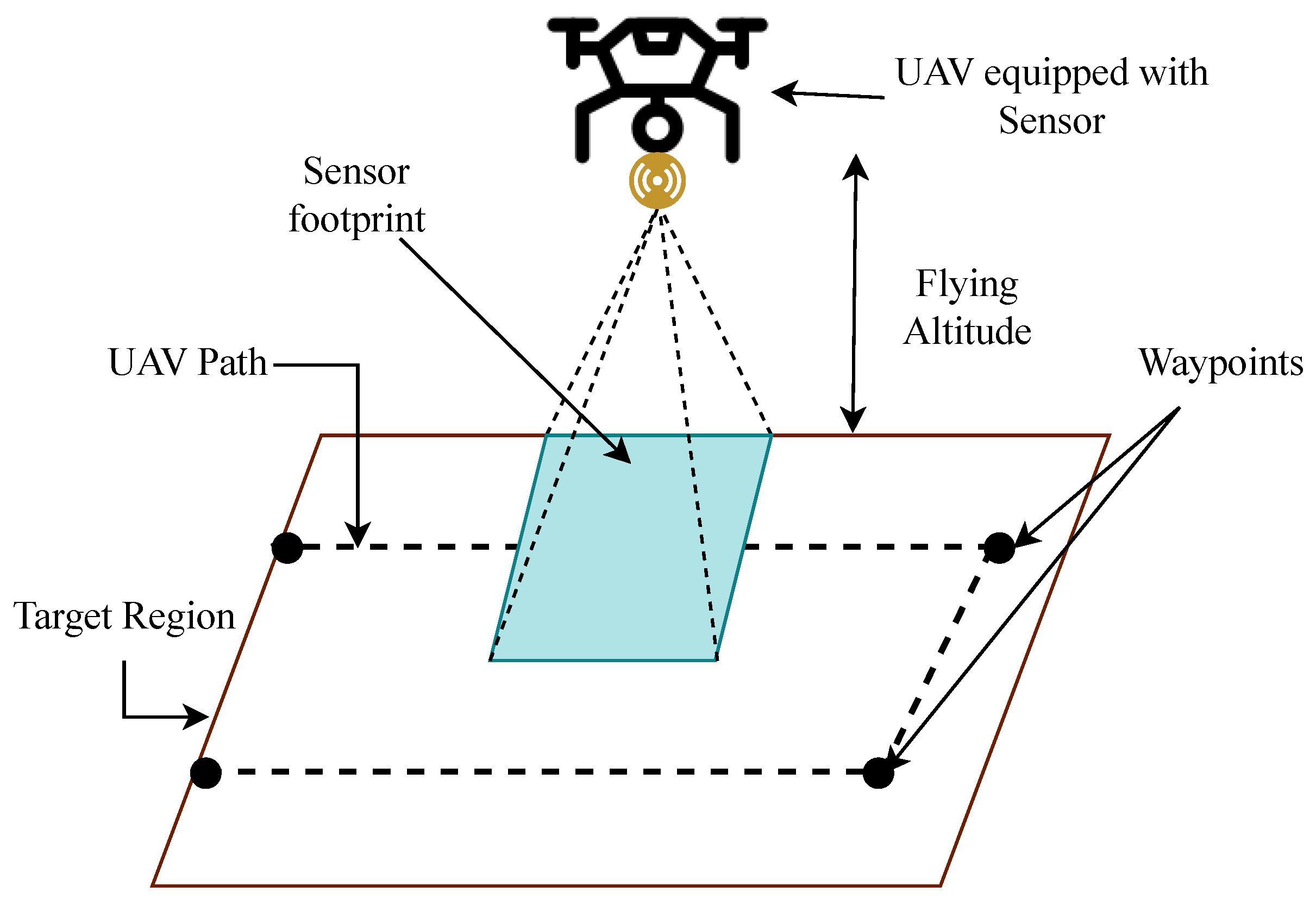
- The path planning strategy is formulated to optimize the coverage route of the UAV-based region survey.
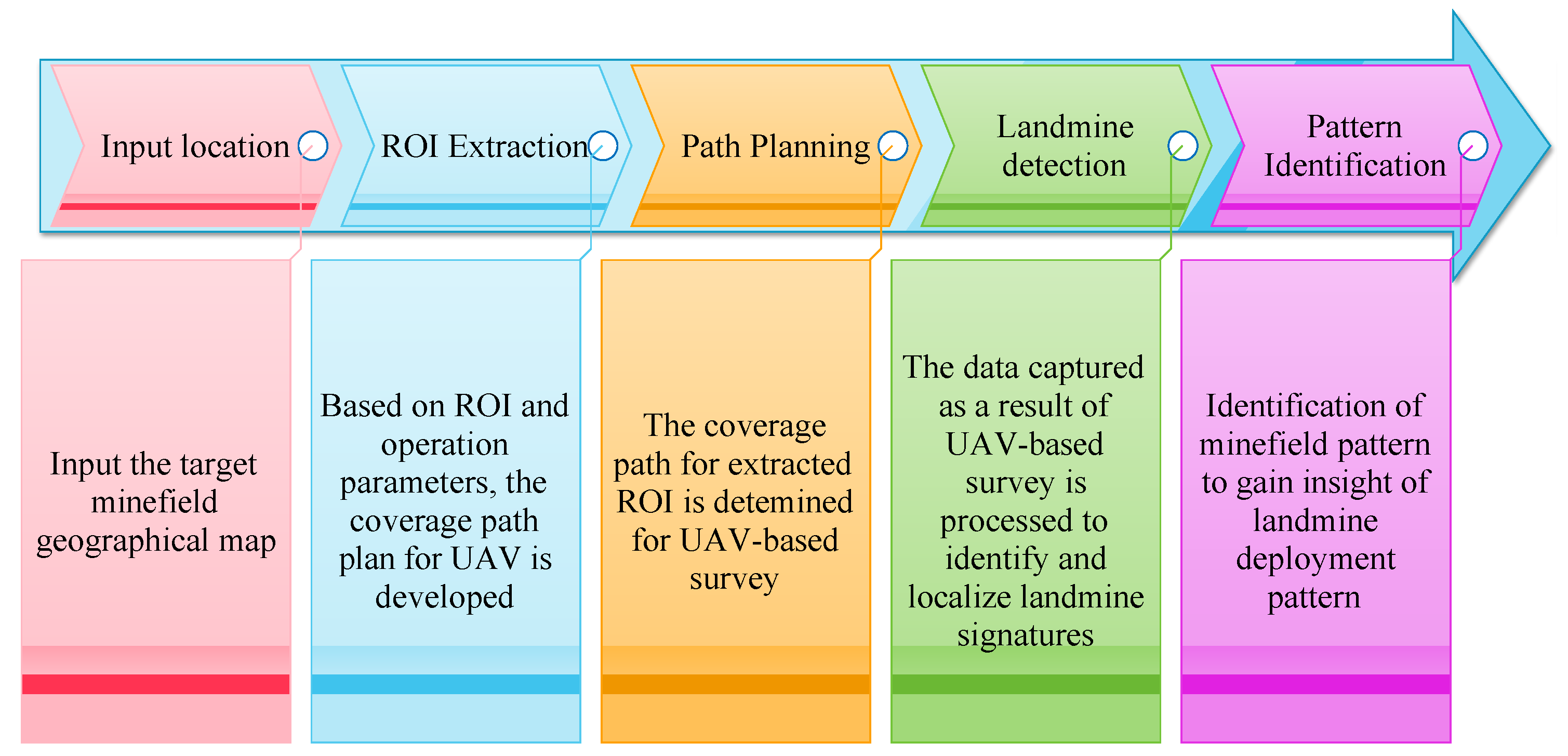
- The workflow is designed for UAV-based minefield surveys.
- The efficacy of the proposed strategy is evaluated in terms of energy and time constraints.
1.2. Organization
2. Background
2.1. UAV-Based Landmine Detection
2.2. Segmentation
2.3. UAV Path Planning
3. Methodology
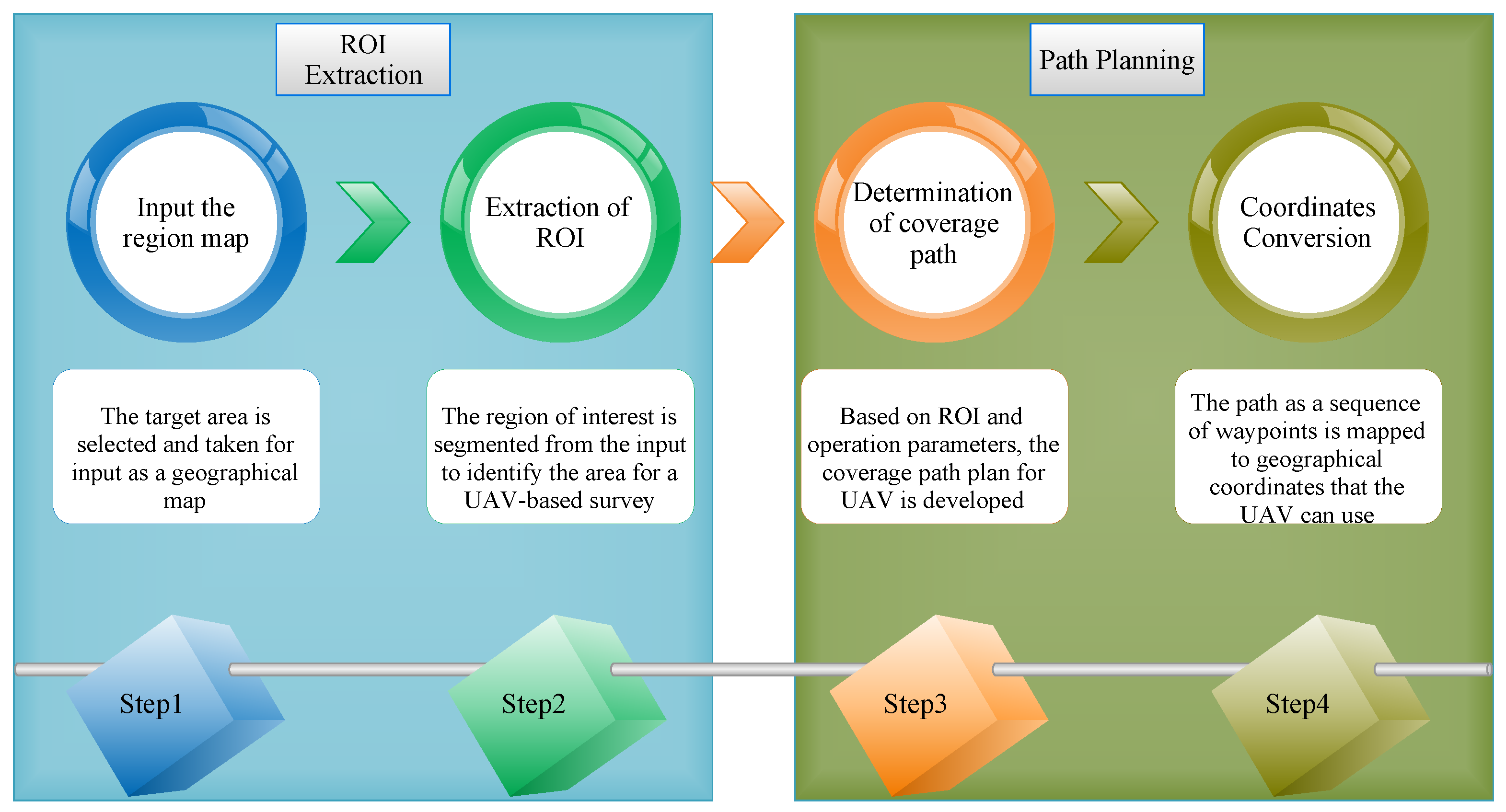
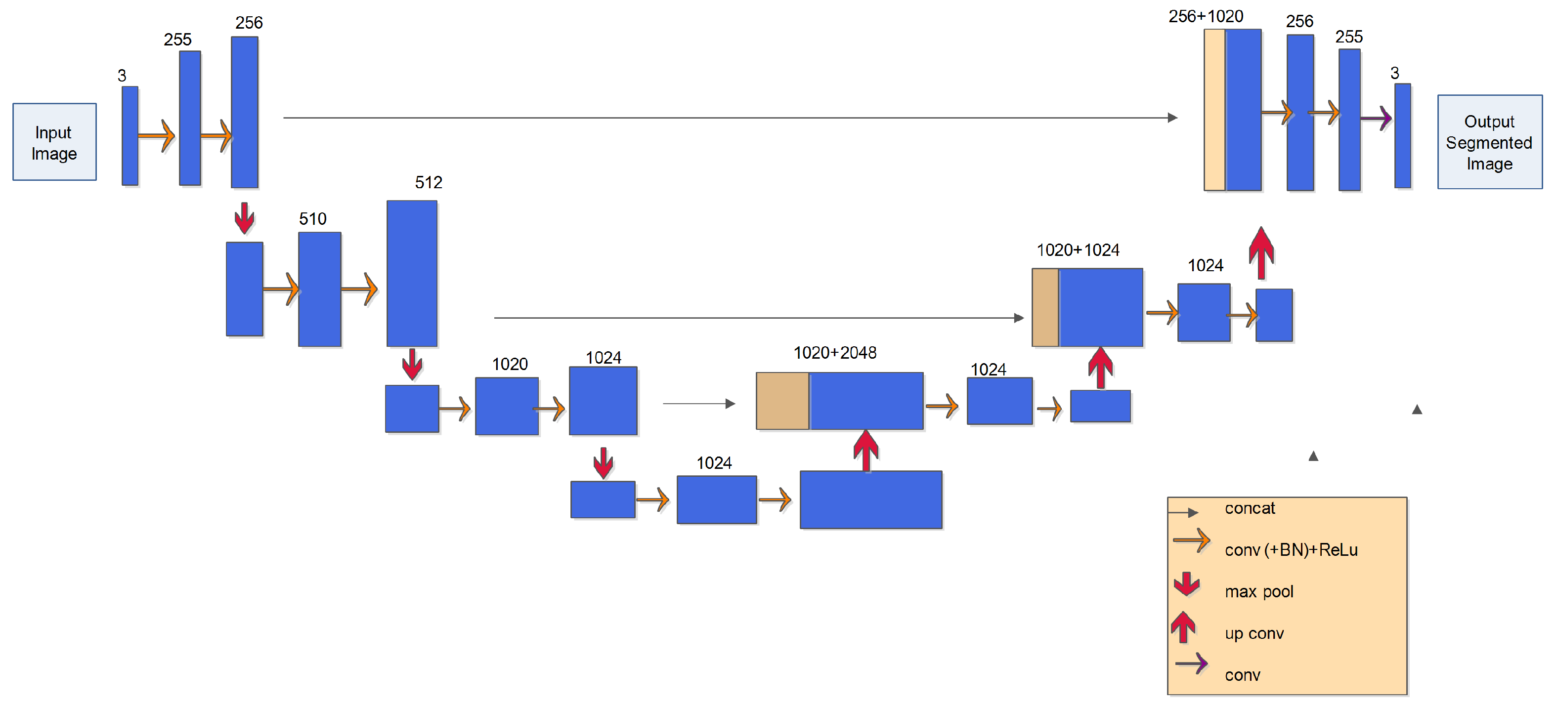
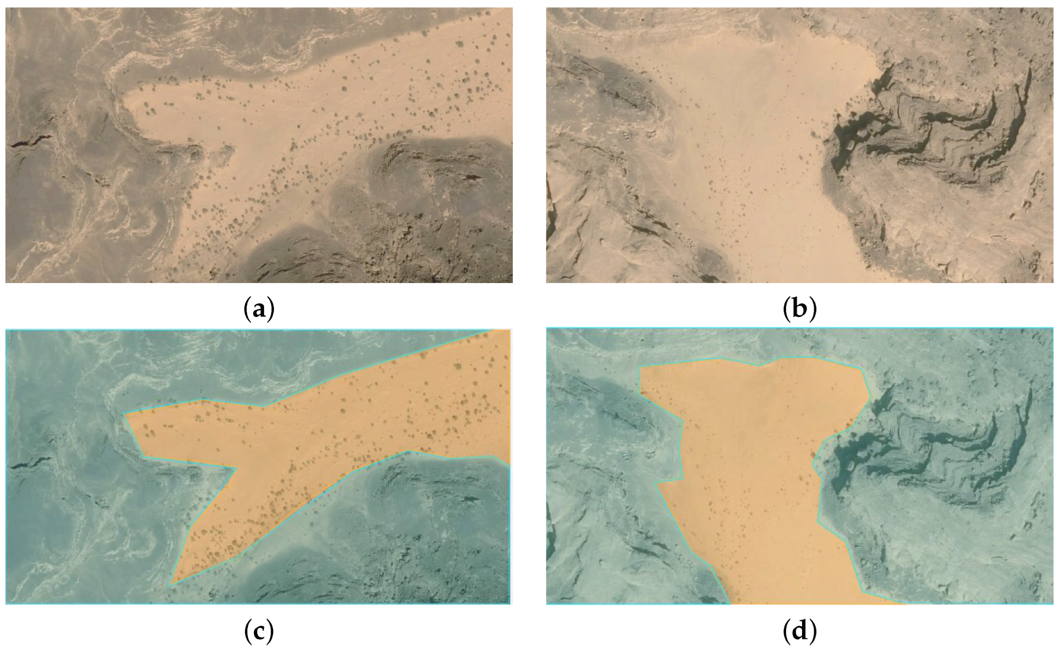
3.1. ROI Segmentation
- Satellite images: U-Net can be used to segment various land cover types, including forests, aquatic bodies, urban areas, and agricultural land, in satellite imagery. The model will produce masks with separate labels for each land cover type. And here, our data takes satellite images of a particular region.
- The U-Net architecture is made to handle small amounts of data: Obtaining big annotated datasets for training deep learning models can be difficult in many real-world applications. Due to its symmetric design and skip connections, U-Net can function well even with little training data. Here, we captured satellite images that are limited in number, so we used the U-Net model for image segmentation.
3.2. Path Planning
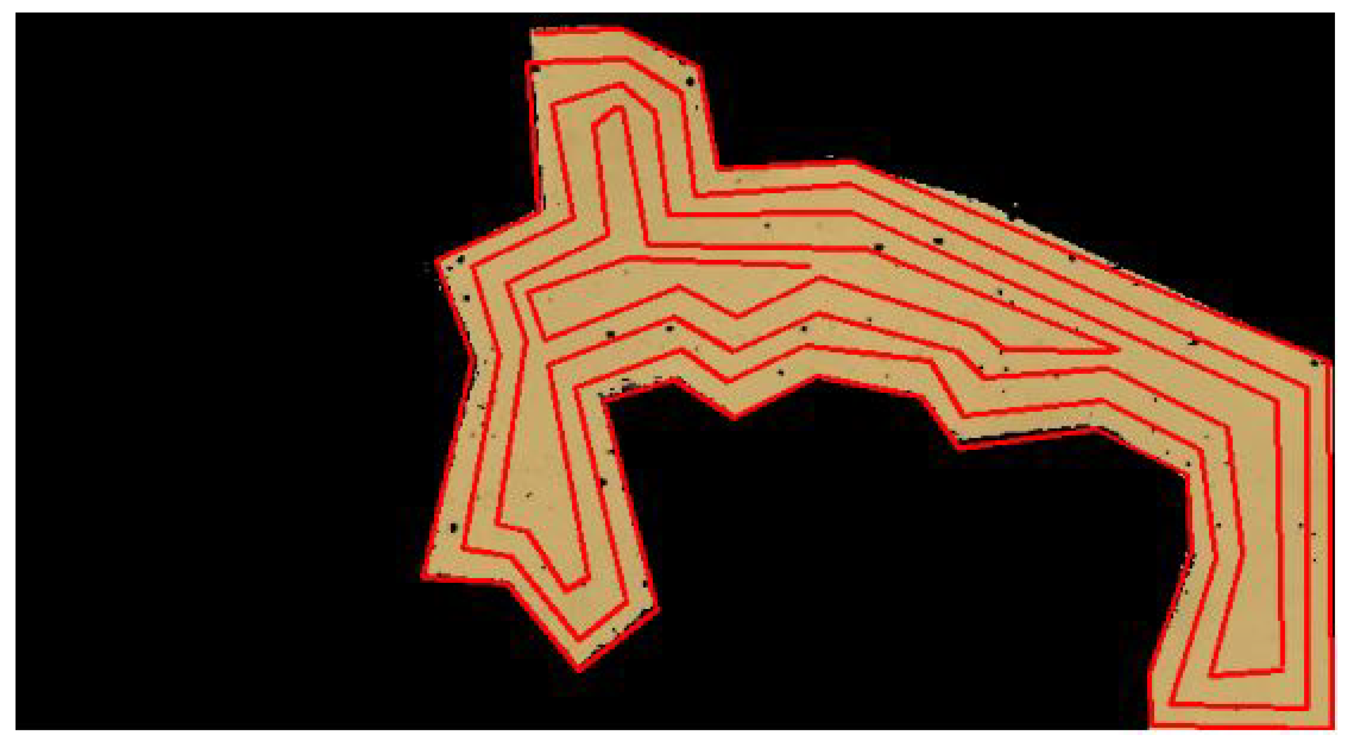
3.2.1. Coverage Path for ROI
| Algorithm 1 Spiral path planning (Spp) algorithm |
| Input: |
Procedure:
|
| return N |
- Lines 2, 3 initialize variables , , , and , which represent the start and end indices of the rows and columns, respectively, stored in the current iteration.
- In line 4, it enters an iteration that continues as long as the start index of the rows is less than or equal to the end index of the rows and the start index of the columns is less than or equal to the end index of the columns.
- Lines 6, 7 use iteration to store the elements in the top row from left to right. The start index of the rows is incremented by 1 to indicate that the top row has been stored.
- In line 8, it again goes into another iteration to store the elements in the rightmost column from top to bottom. The end index of the columns is decremented by 1 to indicate that the rightmost column has been stored.
- In line 10, it checks if there are any rows left. If so, in line 11, it again goes into iteration for the elements in the bottom row from right to left. The end index of the rows is decremented by 1 to indicate that the bottom row has been stored.
- Line 14 checks if there are any columns left. If so, it uses an iteration again for the elements in the leftmost column from bottom to top.
- The start index of the columns is incremented by 1. The iteration continues with the updated indices, and the process is repeated until all elements are stored in ordered nodes (N).
- It then returns the coordinates in an ordered node N.
- The algorithm uses nested loops. The outer while loop continues until both are less than or equal to and are less than or equal to .
- Inside the while loop, there are two nested for loops:
- –
- The first nested for loop iterates over rows within the current column (from to ).
- –
- The second nested for loop iterates over columns within the current row (from to ).
- Additionally, there are two more nested for loops within conditions:
- –
- If <= , a loop iterates over a row in reverse (from to ).
- –
- If <= , a loop iterates over a column in reverse (from to ).
In terms of time complexity:- –
- The first while loop runs at most min() times, where r is the number of rows and c is the number of columns.
- –
- The nested loops inside the while loop are responsible for iterating through submatrices with decreasing dimensions. The total number of iterations performed by these loops can be roughly approximated as O(r*c).

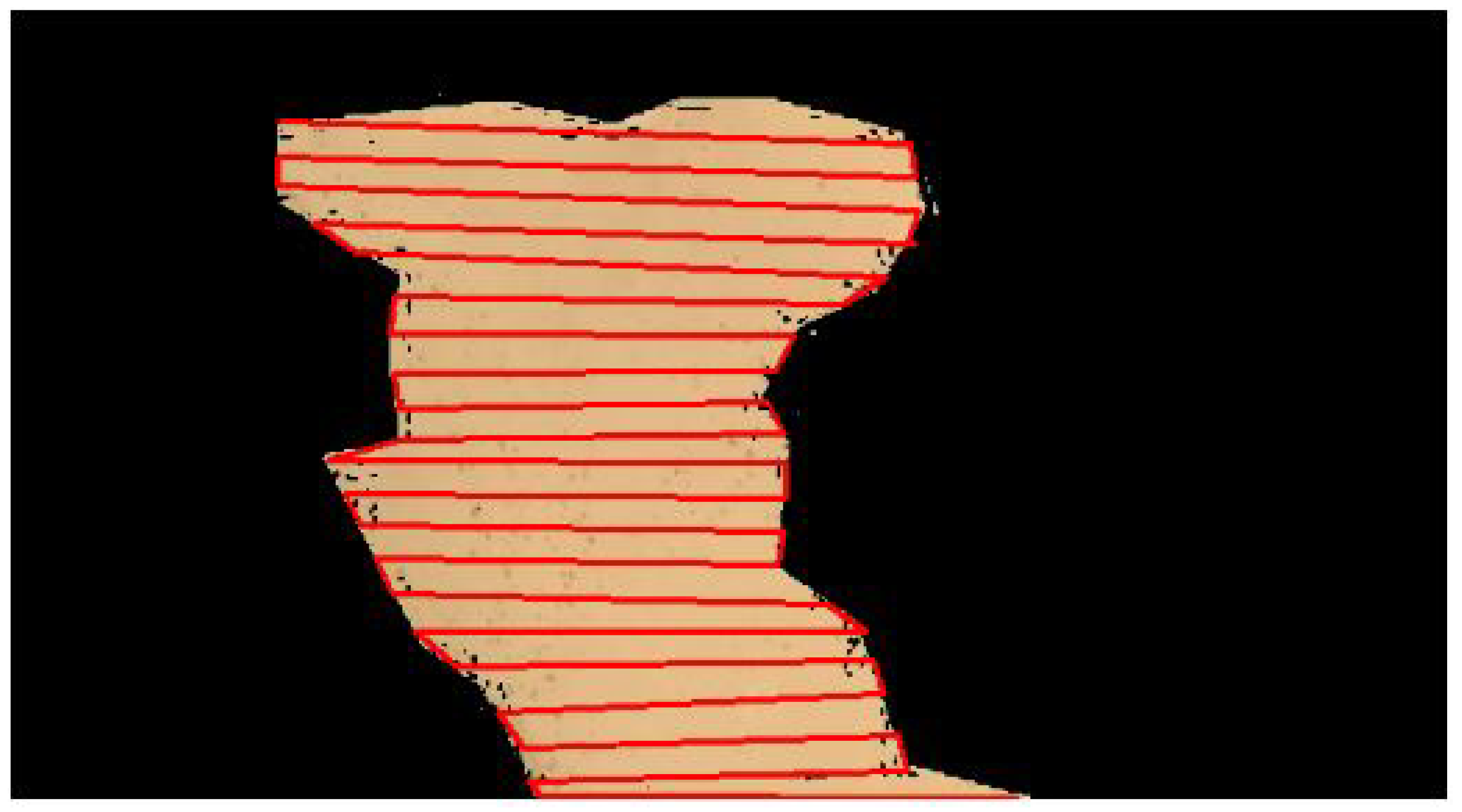
| Algorithm 2 Zig-zag path planning |
Input: : Starting point R:ROI Linewidth:w Output: Waypoints N Procedure:
|
| return N |
- Line 1 points to the starting point and stores it in N. It then initializes variables , and to 0 and 1 respectively (lines 2,3).
- Then it starts with the first iteration (lines 4,5), where it starts with the even row and stores the waypoints of the path in the same direction in N.
- We skip the next row (oddRow) and move to the next evenRow.
- Similarly, it again iterates (line 8) for the odd rows and stores the path waypoints in the opposite direction in N.
- We skip the next row and move to the next even row.
- Finally, we obtain the output in the form of a “path” list as the ordered nodes(N) of the path for the ROI R. Note that this procedure traverses the ROI, R, in a zig-zag pattern, alternating the direction of traversal in each row.
- Initializing N with the values of takes constant time, O(1).
- Initializing variables and takes constant time, O(1).
- The while loop continues as long as is less than r. Each iteration involves a constant number of operations (incrementing and potentially entering the inner loop). The number of iterations is r/2, so the complexity of the while loop is O(r).
- The first for loop iterates over the indices of array , which contains c elements. Each iteration involves a constant number of operations (assigning a value to N and incrementing ). So, the complexity of this loop is O(c).
- The second for loop (inside the first loop) iterates in reverse over the indices of array , which contains c elements. Similar to the previous loop, each iteration involves a constant number of operations. Since this loop only occurs if < r, we can ignore its complexity if is small compared to r.

3.2.2. Coordinates Transformation
4. Experimentation and Results
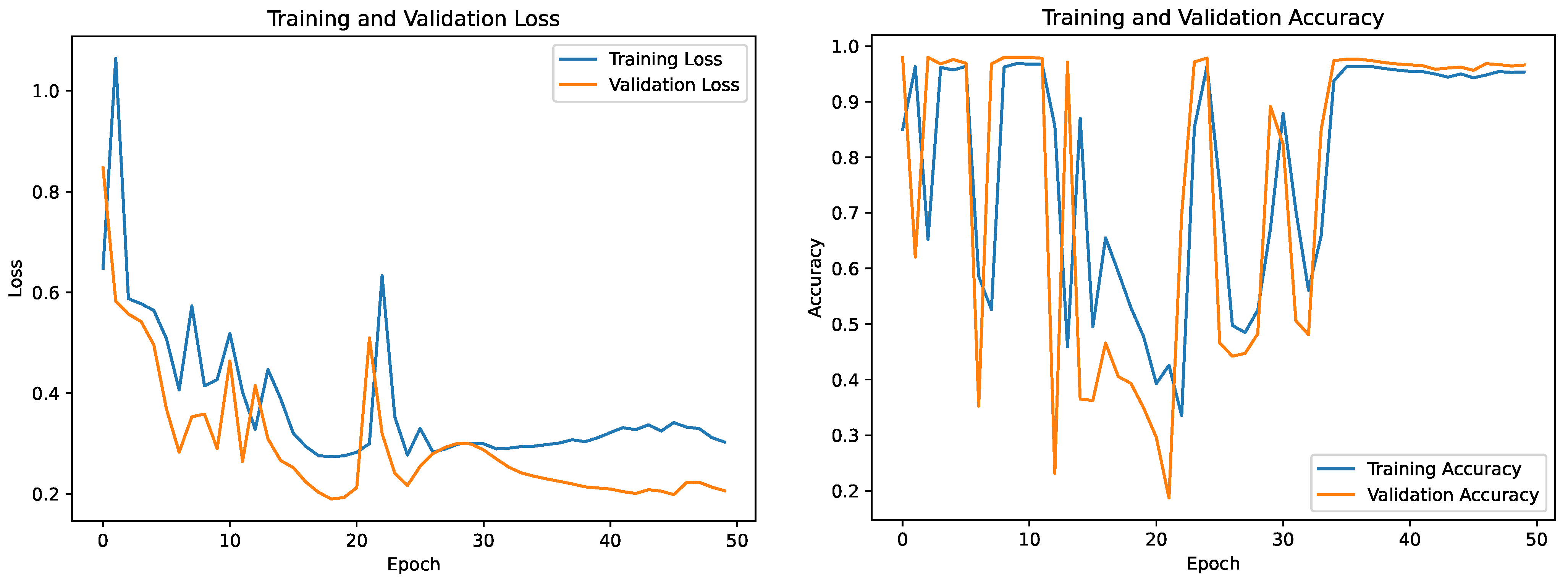
4.1. Segmentation
4.1.1. Dataset
4.1.2. Results
4.2. Path Planning
5. Conclusions
Author Contributions
Funding
Institutional Review Board Statement
Informed Consent Statement
Data Availability Statement
Conflicts of Interest
References
- International Campaign to Ban Landmines. Available online: http://icbl.org/en-gb/problem/what-is-a-landmine.aspx (accessed on 30 December 2022).
- Bello, R. Literature review on landmines and detection methods. Front. Sci. 2013, 3, 27–42. [Google Scholar]
- Landmine Monitor 2022. Available online: http://www.the-monitor.org/en-gb/reports/2022/landmine-monitor-2022.aspx (accessed on 30 December 2022).
- Barnawi, A.; Budhiraja, I.; Kumar, K.; Kumar, N.; Alzahrani, B.; Almansour, A.; Noor, A. A comprehensive review on landmine detection using deep learning techniques in 5G environment: Open issues and challenges. Neural Comput. Appl. 2022, 34, 21657–21676. [Google Scholar] [CrossRef]
- Kasban, H.; Zahran, O.; Elaraby, S.M.; El-Kordy, M.; Abd El-Samie, F.E. A comparative study of landmine detection techniques. Sens. Imaging Int. J. 2010, 11, 89–112. [Google Scholar] [CrossRef]
- Castiblanco, C.; Rodriguez, J.; Mondragon, I.; Parra, C.; Colorado, J. Air drones for explosive landmines detection. In Proceedings of the ROBOT2013: First Iberian Robotics Conference, Madrid, Spain, 28–29 November 2013; Springer: Berlin/Heidelberg, Germany, 2014; pp. 107–114. [Google Scholar]
- Fattah, S.A.; Haider, M.Z.; Chowdhury, D.; Sarkar, M.; Chowdhury, R.I.; Islam, M.S.; Karim, R.; Rahi, A.; Shahnaz, C. An aerial landmine detection system with dynamic path and explosion mode identification features. In Proceedings of the 2016 IEEE Global Humanitarian Technology Conference (GHTC), Seattle, WA, USA, 13–16 October 2016; pp. 745–752. [Google Scholar]
- Colorado, J.; Perez, M.; Mondragon, I.; Mendez, D.; Parra, C.; Devia, C.; Martinez-Moritz, J.; Neira, L. An integrated aerial system for landmine detection: SDR-based Ground Penetrating Radar onboard an autonomous drone. Adv. Robot. 2017, 31, 791–808. [Google Scholar] [CrossRef]
- Schartel, M.; Burr, R.; Mayer, W.; Docci, N.; Waldschmidt, C. UAV-based ground penetrating synthetic aperture radar. In Proceedings of the 2018 IEEE MTT-S International Conference on Microwaves for Intelligent Mobility (ICMIM), Munich, Germany, 15–17 April 2018; pp. 1–4. [Google Scholar]
- Fernández, M.G.; López, Y.Á.; Arboleya, A.A.; Valdés, B.G.; Vaqueiro, Y.R.; Andrés, F.L.H.; García, A.P. Synthetic aperture radar imaging system for landmine detection using a ground penetrating radar on board a unmanned aerial vehicle. IEEE Access 2018, 6, 45100–45112. [Google Scholar] [CrossRef]
- Šipoš, D.; Gleich, D. A lightweight and low-power UAV-borne ground penetrating radar design for landmine detection. Sensors 2020, 20, 2234. [Google Scholar] [CrossRef] [PubMed]
- Garcia-Fernandez, M.; López, Y.Á.; Andrés, F.L.H. Airborne multi-channel ground penetrating radar for improvised explosive devices and landmine detection. IEEE Access 2020, 8, 165927–165943. [Google Scholar] [CrossRef]
- Baur, J.; Steinberg, G.; Nikulin, A.; Chiu, K.; de Smet, T.S. Applying deep learning to automate UAV-based detection of scatterable landmines. Remote Sens. 2020, 12, 859. [Google Scholar] [CrossRef]
- Yoo, L.S.; Lee, J.H.; Ko, S.H.; Jung, S.K.; Lee, S.H.; Lee, Y.K. A drone fitted with a magnetometer detects landmines. IEEE Geosci. Remote. Sens. Lett. 2020, 17, 2035–2039. [Google Scholar] [CrossRef]
- Yoo, L.S.; Lee, J.H.; Lee, Y.K.; Jung, S.K.; Choi, Y. Application of a drone magnetometer system to military mine detection in the demilitarized zone. Sensors 2021, 21, 3175. [Google Scholar] [CrossRef]
- Sultana, F.; Sufian, A.; Dutta, P. Evolution of image segmentation using deep convolutional neural network: A survey. Knowl.-Based Syst. 2020, 201, 106062. [Google Scholar] [CrossRef]
- Rozanda, N.E.; Ismail, M.; Permana, I. Segmentation Google Earth imagery using k-means clustering and normalized RGB color space. In Computational Intelligence in Data Mining; Springer: Berlin/Heidelberg, Germany, 2015; Volume 1, pp. 375–386. [Google Scholar]
- Wang, S.; Yang, D.M.; Rong, R.; Zhan, X.; Xiao, G. Pathology image analysis using segmentation deep learning algorithms. Am. J. Pathol. 2019, 189, 1686–1698. [Google Scholar] [CrossRef]
- Aggarwal, S.; Kumar, N. Path planning techniques for unmanned aerial vehicles: A review, solutions, and challenges. Comput. Commun. 2020, 149, 270–299. [Google Scholar] [CrossRef]
- Galceran, E.; Carreras, M. A survey on coverage path planning for robotics. Robot. Auton. Syst. 2013, 61, 1258–1276. [Google Scholar] [CrossRef]
- Cabreira, T.M.; Brisolara, L.B.; Paulo R, F.J. Survey on coverage path planning with unmanned aerial vehicles. Drones 2019, 3, 4. [Google Scholar] [CrossRef]
- Li, Y.; Chen, H.; Er, M.J.; Wang, X. Coverage path planning for UAVs based on enhanced exact cellular decomposition method. Mechatronics 2011, 21, 876–885. [Google Scholar] [CrossRef]
- Coombes, M.; Fletcher, T.; Chen, W.H.; Liu, C. Optimal polygon decomposition for UAV survey coverage path planning in wind. Sensors 2018, 18, 2132. [Google Scholar] [CrossRef]
- Valente, J.; Sanz, D.; Del Cerro, J.; Barrientos, A.; de Frutos, M.Á. Near-optimal coverage trajectories for image mosaicing using a mini quad-rotor over irregular-shaped fields. Precis. Agric. 2013, 14, 115–132. [Google Scholar] [CrossRef]
- Di Franco, C.; Buttazzo, G. Coverage path planning for UAVs photogrammetry with energy and resolution constraints. J. Intell. Robot. Syst. 2016, 83, 445–462. [Google Scholar] [CrossRef]
- Pérez-González, A.; Benítez-Montoya, N.; Jaramillo-Duque, Á.; Cano-Quintero, J.B. Coverage path planning with semantic segmentation for UAV in PV plants. Appl. Sci. 2021, 11, 12093. [Google Scholar] [CrossRef]
- Nedjati, A.; Izbirak, G.; Vizvari, B.; Arkat, J. Complete coverage path planning for a multi-UAV response system in post-earthquake assessment. Robotics 2016, 5, 26. [Google Scholar] [CrossRef]
- Zhang, H.; Xin, B.; Dou, L.h.; Chen, J.; Hirota, K. A review of cooperative path planning of an unmanned aerial vehicle group. Front. Inf. Technol. Electron. Eng. 2020, 21, 1671–1694. [Google Scholar] [CrossRef]
- Araujo, J.; Sujit, P.; Sousa, J.B. Multiple UAV area decomposition and coverage. In Proceedings of the 2013 IEEE Symposium on Computational Intelligence for Security and Defense Applications (CISDA), Singapore, 16–19 April 2013; pp. 30–37. [Google Scholar]
- Azpúrua, H.; Freitas, G.M.; Macharet, D.G.; Campos, M.F. Multi-robot coverage path planning using hexagonal segmentation for geophysical surveys. Robotica 2018, 36, 1144–1166. [Google Scholar] [CrossRef]
- Guastella, D.C.; Cantelli, L.; Giammello, G.; Melita, C.D.; Spatino, G.; Muscato, G. Complete coverage path planning for aerial vehicle flocks deployed in outdoor environments. Comput. Electr. Eng. 2019, 75, 189–201. [Google Scholar] [CrossRef]
- Choi, Y.; Choi, Y.; Briceno, S.; Mavris, D. Energy-constrained multi-UAV coverage path planning for an aerial imagery mission using column generation. J. Intell. Robot. Syst. 2020, 97, 125–139. [Google Scholar] [CrossRef]
- Cao, Y.; Cheng, X.; Mu, J. Concentrated Coverage Path Planning Algorithm of UAV Formation for Aerial Photography. IEEE Sensors J. 2022, 22, 11098–11111. [Google Scholar] [CrossRef]
- Cho, S.W.; Park, H.J.; Lee, H.; Shim, D.H.; Kim, S.Y. Coverage path planning for multiple unmanned aerial vehicles in maritime search and rescue operations. Comput. Ind. Eng. 2021, 161, 107612. [Google Scholar] [CrossRef]
- Xie, J.; Carrillo, L.R.G.; Jin, L. An integrated traveling salesman and coverage path planning problem for unmanned aircraft systems. IEEE Control. Syst. Lett. 2018, 3, 67–72. [Google Scholar] [CrossRef]
- Xie, J.; Carrillo, L.R.G.; Jin, L. Path planning for UAV to cover multiple separated convex polygonal regions. IEEE Access 2020, 8, 51770–51785. [Google Scholar] [CrossRef]


| Parameter | Value |
|---|---|
| UAV Max speed | 5 m/s, 10 m/s |
| Altitude | 1 m, 5 m |
| Line Gap | 3 m, 10 m |
| Overlap | 0.5, 0.5 |
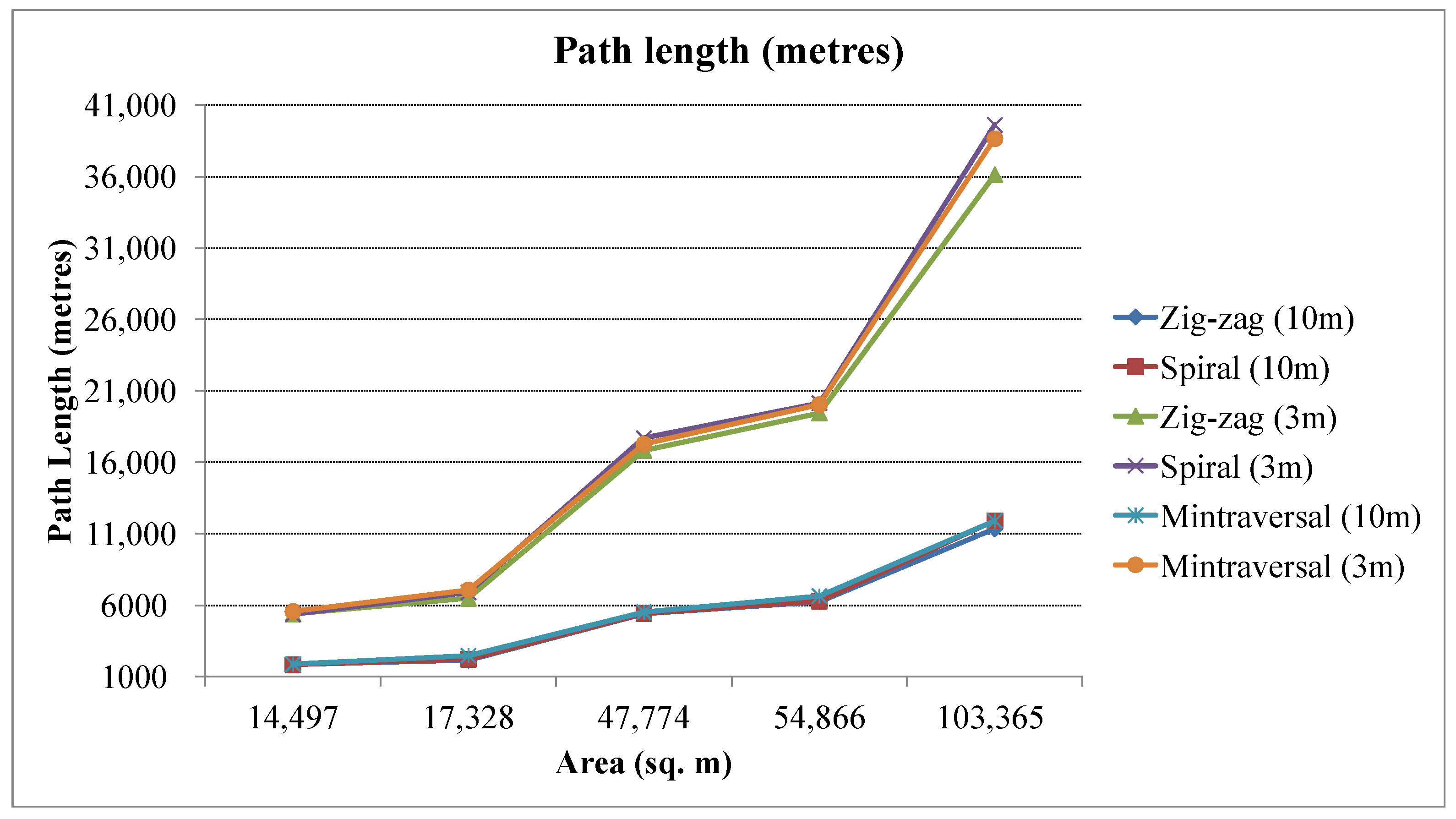
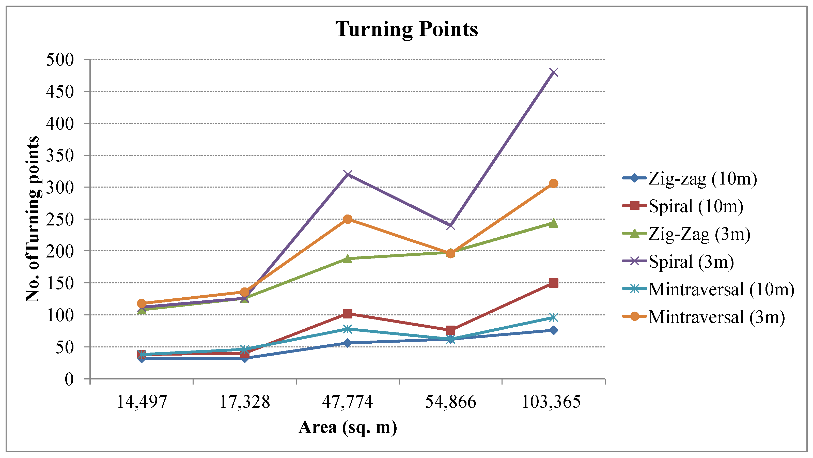
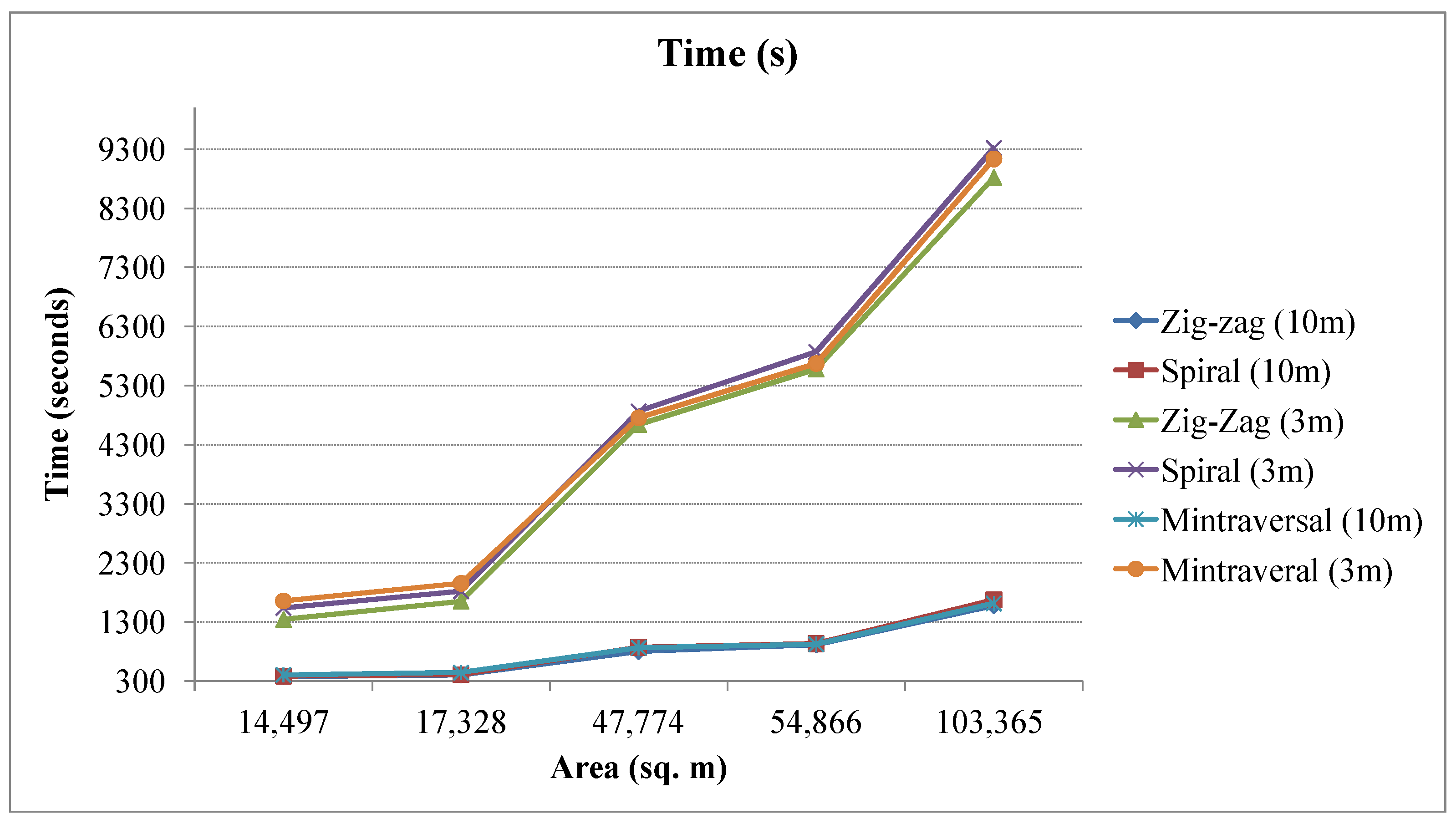
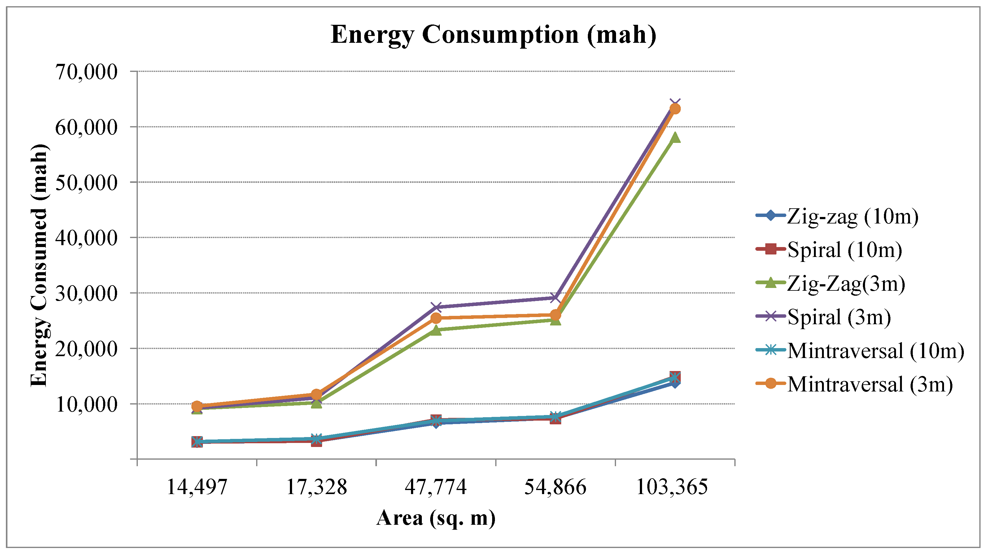
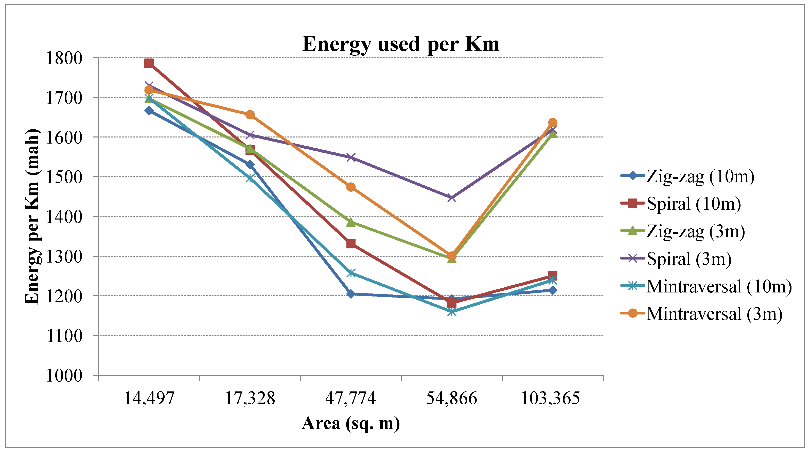
| Sample | Area | Path | Path Length | Time(s) | Energy Consumed | Energy mAh/Km | No. of Turning Points | Average Speed |
|---|---|---|---|---|---|---|---|---|
| S1 | 14,497 | Zig-zag | 1849.64 | 385 | 3083 | 1666.81 | 32 | 4.8 |
| S2 | 17,328 | Zig-zag | 2154 | 410 | 3298 | 1530.78 | 32 | 5.32 |
| S3 | 47,774 | Zig-zag | 5405.41 | 801 | 6514 | 1205.09 | 56 | 6.75 |
| S4 | 54,866 | Zig-zag | 6235.49 | 915 | 7435 | 1192.37 | 62 | 6.81 |
| S5 | 103,365 | Zig-zag | 11,350.54 | 1575 | 13,785 | 1214.47 | 76 | 7.21 |
| S1 | 14,497 | Spiral | 1750.99 | 385 | 3128 | 1786.42 | 38 | 4.55 |
| S2 | 17,328 | Spiral | 2223.95 | 405 | 3264 | 1467.66 | 40 | 5.42 |
| S3 | 47,774 | Spiral | 5334.95 | 872 | 7103 | 1331.41 | 102 | 6.12 |
| S4 | 54,866 | Spiral | 6295.56 | 900 | 7317 | 1162.25 | 76 | 6.99 |
| S5 | 103,365 | Spiral | 11915 | 1675 | 14,898 | 1250.36 | 150 | 7.11 |
| S1 | 14,497 | minTraversal | 1876.74 | 405 | 3187 | 1698.15 | 38 | 4.63 |
| S2 | 17,328 | minTraversal | 2473.92 | 445 | 3703 | 1496.81 | 46 | 5.56 |
| S3 | 47,774 | minTraversal | 5522.08 | 865 | 6945 | 1257.67 | 78 | 6.38 |
| S4 | 54,866 | minTraversal | 6645.74 | 925 | 7710 | 1160.14 | 62 | 7.18 |
| S5 | 103,365 | minTraversal | 11,901.89 | 1615 | 14,756 | 1239.80 | 96 | 7.36 |
Disclaimer/Publisher’s Note: The statements, opinions and data contained in all publications are solely those of the individual author(s) and contributor(s) and not of MDPI and/or the editor(s). MDPI and/or the editor(s) disclaim responsibility for any injury to people or property resulting from any ideas, methods, instructions or products referred to in the content. |
© 2023 by the authors. Licensee MDPI, Basel, Switzerland. This article is an open access article distributed under the terms and conditions of the Creative Commons Attribution (CC BY) license (https://creativecommons.org/licenses/by/4.0/).
Share and Cite
Barnawi, A.; Kumar, K.; Kumar, N.; Thakur, N.; Alzahrani, B.; Almansour, A. Unmanned Ariel Vehicle (UAV) Path Planning for Area Segmentation in Intelligent Landmine Detection Systems. Sensors 2023, 23, 7264. https://doi.org/10.3390/s23167264
Barnawi A, Kumar K, Kumar N, Thakur N, Alzahrani B, Almansour A. Unmanned Ariel Vehicle (UAV) Path Planning for Area Segmentation in Intelligent Landmine Detection Systems. Sensors. 2023; 23(16):7264. https://doi.org/10.3390/s23167264
Chicago/Turabian StyleBarnawi, Ahmed, Krishan Kumar, Neeraj Kumar, Nisha Thakur, Bander Alzahrani, and Amal Almansour. 2023. "Unmanned Ariel Vehicle (UAV) Path Planning for Area Segmentation in Intelligent Landmine Detection Systems" Sensors 23, no. 16: 7264. https://doi.org/10.3390/s23167264