
Smart Task Assistance in Mixed Reality for Astronauts
by
Qingwei Sun
1,2,
Wei Chen
2,3,
Jiangang Chao
2,3,*,
Wanhong Lin
2,3,
Zhenying Xu
2,3 and
Ruizhi Cao
4 1
Department of Aerospace Science and Technology, Space Engineering University, Beijing 101416, China
2
China Astronaut Research and Training Center, Beijing 100094, China
3
National Key Laboratory of Human Factor Engineering, China Astronaut Research and Training Center, Beijing 100094, China
4
School of Computer Science and Engineering, Beihang University, Beijing 100083, China
*
Author to whom correspondence should be addressed.
Sensors 2023, 23(9), 4344; https://doi.org/10.3390/s23094344
Submission received: 13 April 2023
/
Revised: 24 April 2023
/
Accepted: 25 April 2023
/
Published: 27 April 2023
(This article belongs to the Special Issue Vision Sensors for Object Detection and Recognition)
Abstract
:Mixed reality (MR) registers virtual information and real objects and is an effective way to supplement astronaut training. Spatial anchors are generally used to perform virtual–real fusion in static scenes but cannot handle movable objects. To address this issue, we propose a smart task assistance method based on object detection and point cloud alignment. Specifically, both fixed and movable objects are detected automatically. In parallel, poses are estimated with no dependence on preset spatial position information. Firstly, YOLOv5s is used to detect the object and segment the point cloud of the corresponding structure, called the partial point cloud. Then, an iterative closest point (ICP) algorithm between the partial point cloud and the template point cloud is used to calculate the object’s pose and execute the virtual–real fusion. The results demonstrate that the proposed method achieves automatic pose estimation for both fixed and movable objects without background information and preset spatial anchors. Most volunteers reported that our approach was practical, and it thus expands the application of astronaut training.
1. Introduction
Traditional astronaut training methods contain instructor-led instruction, querying manuals, voice guidance, etc. However, these methods require astronauts to memorize and query operational processes, increasing the task burden [1,2]. To solve this problem, MR is applied to provide virtual assistance information, such as process guidance [3], equipment operation simulation [1], etc., Refs. [4,5], on the astronaut’s headset. In practice, MR provides astronauts with intuitive operation guidance, freeing them from complicated manuals, reducing brain load and operation errors, and meeting the needs of autonomous training.
The core of MR is the fusion of virtual information and real objects in 3D space. The key point is to determine the pose of objects relative to the MR device to ensure that the hologram can be accurately projected. In application development, spatial anchors are generally preset [6], and the pose of the virtual information is adjusted manually. However, this mode is only applied in scenes with fixed objects due to the lack of automatic pose estimation. As the environment changes significantly, spatial anchors need to be updated. Some presented works also propose preload markers on the object, which can solve the problem effectively [7,8]. However, we do not want to add extra information to the natural scene when training. Neither of these models can meet the application requirements for moving objects in the environment.
For the reasons above, conventional MR devices only perform recognition of the geometric space and cannot detect specific objects or perceive the dynamic changes in the scene. To meet the MR training needs, it is crucial to develop a method that is not limited by static space.
We break down this issue into discovering objects and estimating poses. Deep learning-based object detection is widely used to detect objects. According to whether the method generates proposals, object detection is divided into two types, namely two-stage methods [9,10,11,12,13] and one-stage methods [14,15,16,17,18,19]. Two-stage methods are characterized by generating proposals first and then classifying the objects and are slower than one-stage methods.
The purpose of pose estimation is to determine the 6DoF pose of the object in 3D space, including translation and rotation. Generally, there are three types of methods to solve this problem. The first is the correspondence point-based method [20,21,22,23,24], which finds the matching relationship between the input data and the point cloud of the object. The second is the template-based approach [25,26,27,28], where a template similar to the object is selected from a marked pose library. The third is the voting-based approach [29,30,31], with the idea that each 2D pixel or 3D point contributes to the 6DoF pose. In MR applications, the low-resolution images acquired by visual sensors and the soft texture of the astronaut training environment prevent the stable extraction of 2D features. Fortunately, TOF or stereo cameras can obtain the object’s depth, so the ICP algorithm can be used.
In work similar to ours [32], Mask-RCNN is used to segment instances. Both 2.5D and 3D replicas are extracted from the spatial mapping generated by instances to enhance the perception of the scene. Furthermore, Mask-RCNN is also used in the subsequent work [33], and the CAD point cloud is aligned with the object point cloud through the ICP algorithm. Unlike our method, Park et al.’s work requires the virtual model to be registered to markers beforehand. At the same time, the background of the astronaut training environment is more complex, and the object is quite small, making pose estimation challenging.
To address the limitation that MR cannot automatically detect objects, we propose a pose estimation method based on object detection and point cloud alignment. Indeed, objects in astronaut training are small. They occupy a small percentage of pixels, which poses a significant challenge to traditional image processing methods. In practice, we use YOLOv5s [14] to detect small samples and irregular objects. Furthermore, the partial point cloud is segmented and is ICP-aligned [34] with the template point cloud to estimate the pose of objects.
In experiments, fixed and movable objects are selected for MR. Subjects with different backgrounds are invited to experience our system. Results show that the proposed method effectively improves MR scene comprehension and extends the methods of astronaut MR training. The contributions of this study are as follows:
- We propose a smart MR task assistance method based on object detection and point cloud alignment to meet the requirements of pose estimation of fixed and movable objects.
- Aiming at the specific setting of astronaut training, YOLOv5s and ICP are used to detect objects and calculate poses, respectively.
- The results demonstrate the usability and usefulness of the proposed method, providing a new method for subsequent research.
2. Materials and Methods
Our method focuses on object detection and pose estimation in astronaut training and guides the virtual information to be accurately rendered onto the real object. Specifically, we remove the limitation of preset poses and solve the problem of inaccurate registration between virtual information and movable objects. Unlike in the work of Park et al. [33], the objects in our images are small, and the depth measurement is inaccurate. Therefore, the point cloud obtained from a single view is incomplete, which poses a significant challenge to the pose estimation. Given this scene’s characteristics, YOLOv5s is combined with the ICP algorithm to execute pose estimation in MR applications. Firstly, YOLOv5s is used to find the object’s bounding box on the RGB image. Secondly, the partial point cloud of the object is calculated based on its corresponding depth value. Finally, the object’s pose is calculated by aligning it with the template point cloud. Furthermore, the pose is applied to the astronaut MR to enhance the system’s robustness and smartness.
2.1. Overview of the Proposed Method
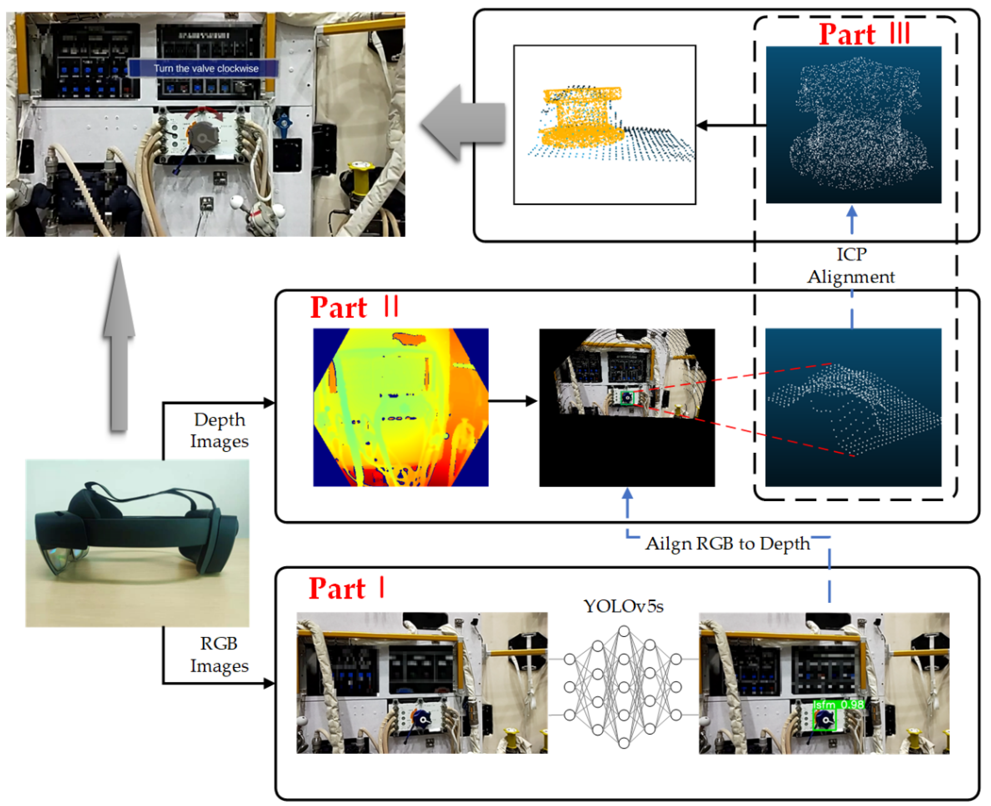
As shown in Figure 1, the algorithm utilizes HoloLens2 as the MR device and is divided into three main parts. Part I is object detection, where YOLOv5s is used to obtain the object’s bounding box on the RGR image, i.e., the pixel coordinates of the four corners of the rectangular box. Part II is the generation of the partial point cloud, including (a) alignment of the RGB image with the depth image, (b) determination of the coordinates of the bounding box on the depth image, and (c) calculation of the point cloud of the corresponding region based on intrinsic parameters and depth values. Part III calculates the pose of the partial point cloud relative to the template point cloud, i.e., the object’s pose relative to the camera coordinate system, using ICP, where the template point cloud is obtained by sampling from the CAD model.
The world coordinate system of the camera can be obtained through SLAM and the extrinsic parameters between sensors in HoloLens2. Therefore, the object’s pose relative to the world coordinate system, i.e., a fixed position in 3D space, can be obtained. Furthermore, this pose can register the virtual information used for astronaut training with the real object.
Communication between HoloLens2 and the server is performed via UDP. HoloLens2 transmits depth, RGB images, and each sensor’s intrinsic and extrinsic parameters to the server. The server sends the object’s pose to HoloLens2. The pose includes translation and rotation, where the translation is defined as , and rotation is defined as a quaternion: . Considering the performance of HoloLens2 and the server’s processing capacity, the data-sending frequency of HoloLens2 is three fps. If the frequency is too high, it will store the data in the queue and increase the latency. Indeed, the latency becomes more pronounced as the program runs longer. In practice, the time consumption of ICP on our device is about 0.187 s per frame, which will be completed before the subsequent frame transmission.
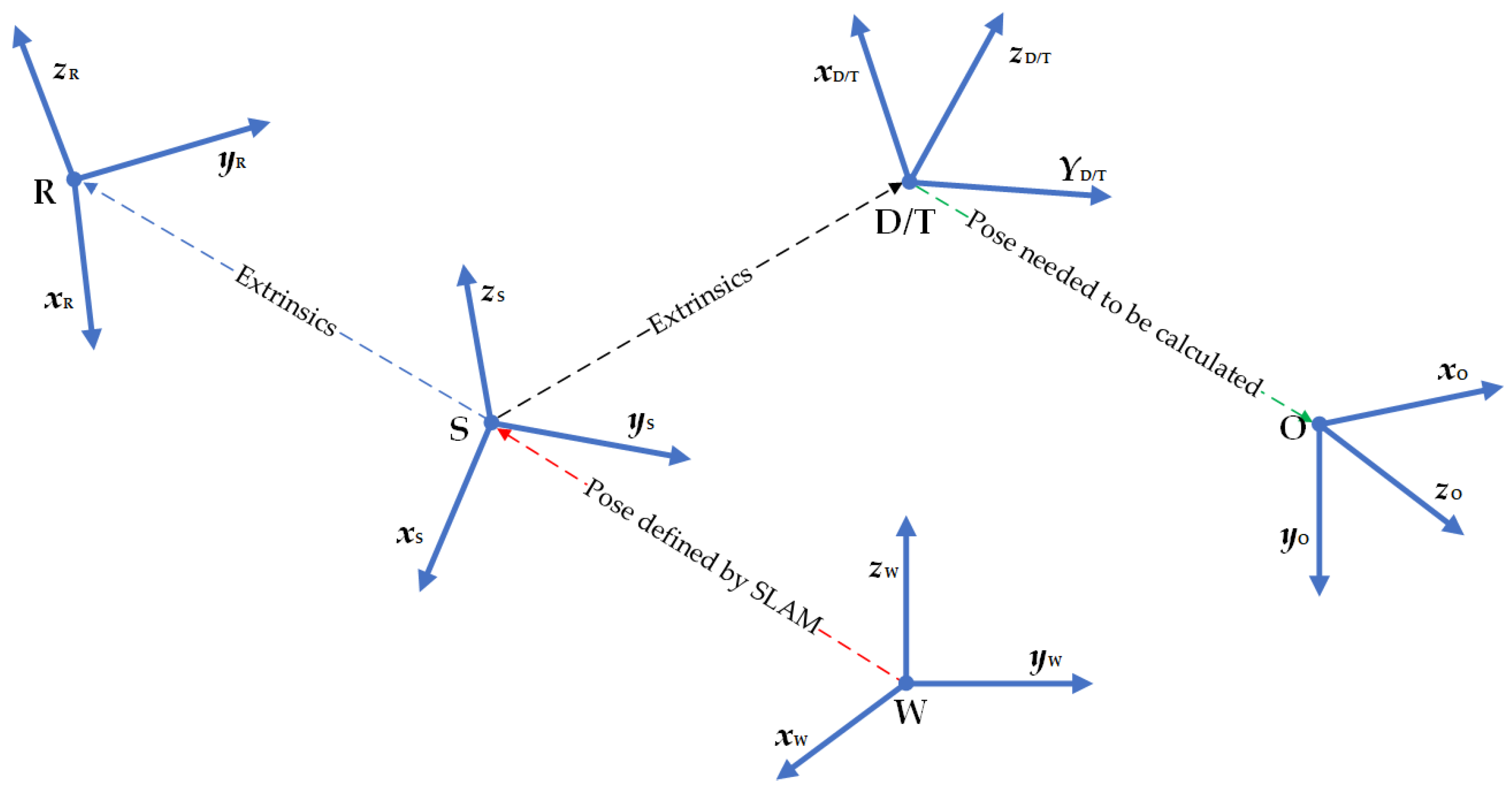
2.2. Transformation of Coordinate Systems
The proposed method involves transformation between multiple coordinate systems, as shown in Figure 2. W is the world coordinate system, the initial coordinate system of the entire system, determined by the HoloLens2 boot position. S is the system coordinate system of HoloLens2, called the rigNode in [35], and HoloLens2 provides extrinsic parameters of all sensors relative to S. R is the RGB camera coordinate system. D is the depth camera coordinate system. We align the RGB image to the depth image.
From the transformation of R relative to S and the transformation of D relative to S, the following relationship can be obtained:
T is the coordinate system where the template point cloud is located. In our method, T is set to be the same as D to simplify the pose calculation’s complexity. O is the coordinate system where the object is located.
The key to MR is to determine the transformation of O relative to S, i.e., to find , which is expressed as a translation and a rotation . can be obtained by SLAM, which is considered known. Therefore, by obtaining , the absolute coordinates of the object in the world coordinate system can be defined as . T coincides with D, so define , which can be obtained from extrinsic parameters and is considered known. The process of calculating can be translated into calculating , i.e., . Our goal is to calculate .
Note that the above coordinate system follows a right-handed coordinate system. The application is developed using Unity, which follows a left-handed coordinate system, so the pose obtained by HoloLens2 needs to be transformed into a left-handed coordinate system. In the coordinate system transformation, a distinction should be made between translation and rotation, and the two cases should be handled separately [36].
The translation involves a transformation of the point positions as long as the corresponding axes are inverted. Taking the Z-axis as an example, the point in the right-hand system is transformed into the point in the left-hand system, which is represented by the matrix as the following:
The transformation matrix for translation is as follows:
Assuming that the rotation matrix in the right-handed system is , and the rotation matrix in the left-handed system is , then we define the following:
Equation (4) is the rotation matrix in the left-handed coordinate system. Equations (2) and (4) can be used to convert the poses in the right-handed coordinate system over to the left-handed coordinate system.
2.3. Object Detection Based on YOLOv5s
2.3.1. YOLOv5s
There are several versions of YOLOv5, among which YOLOv5s is the simplest. The remaining ones are extended on this basis. Astronaut training scenes are relatively unchanged and do not require the network to have too high of a generalization ability, so that YOLOv5s can meet the demand.
YOLOv5s is divided into four parts: input, backbone, neck, and prediction. Among them, the input adopts Mosaic data enhancement. In practice, four images are stitched together by random scaling, random cropping, and random arrangement, which improves the detection of the small object. This reduces training dependence on batch size and is more suitable for the particular scene of astronauts. Moreover, Focus and CSP (Cross Stage Partial Network) are used in the backbone. The Focus slices the image, expands the input image of three channels to twelve channels, performs sampling of images, and retains information completely, compared with traditional sampling. The CSP performs a two-step operation on feature maps: one is convolution, and the other combines the results of the previous convolution, similar to ResNet [37]. CSP brings significant improvement, effectively enhancing the ability of CNN and reducing calculation. Then, the neck part changes the convolution to the CSP, further improving the network’s power. In the prediction part, YOLOv5s fuses the results of three different resolutions and maps them to the same size as the input image.
The above characteristics make the YOLOv5s able to be trained faster with small datasets and detect small-sized objects more accurately. So, we choose YOLOv5s as the network for object detection.
2.3.2. Datasets
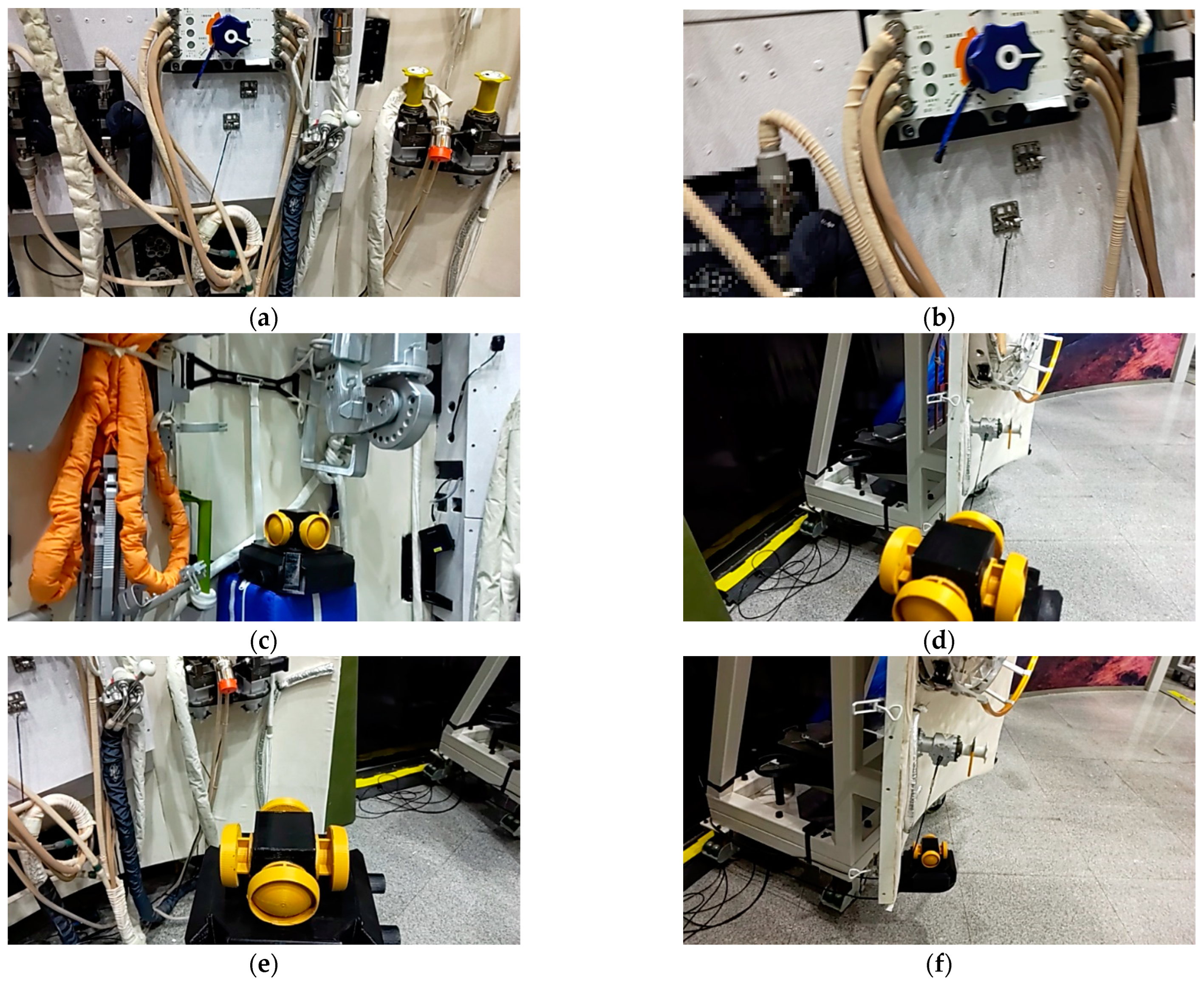
Astronauts work in a relatively unchanged environment, and two frequently operated objects are selected, including a valve and a panoramic camera. We use HoloLens2 to scan the scene, and the data stream is saved as images. Five hundred are selected, 400 of which are used as the training set and the other 100 as the validation set. Some of the data are shown in Figure 3.
It should be noted that some of the data are blurred, as shown in Figure 3.
Figure 3b is normal and reasonable. This is caused by the movement of the HoloLens2 while capturing images, which often happens in natural application scenes.
A large amount of labeled data like COCO cannot be acquired in the experiment, and the image resolution captured by HoloLens2 is poor. Compared with the general case, this application is characterized by small samples and low resolution, which creates higher requirements. Fortunately, the astronaut training scene is unchanged. For object detection, there is a high similarity between the train and test datasets, so the strong generalization ability of the network is not required. Meanwhile, Mosaic and self-adversarial trainings (SAT) are used in YOLOv5s for data augmentation, which expands the dataset.
2.3.3. Network Training
The developing environment and parameters are shown in Table 1, and YOLOv5s is fine-tuned based on the pre-training weights. Since our dataset is relatively small, we use a small batch size to meet the training requirements. The optimization algorithm is stochastic gradient descent (SGD), and CUDA accelerates the training.
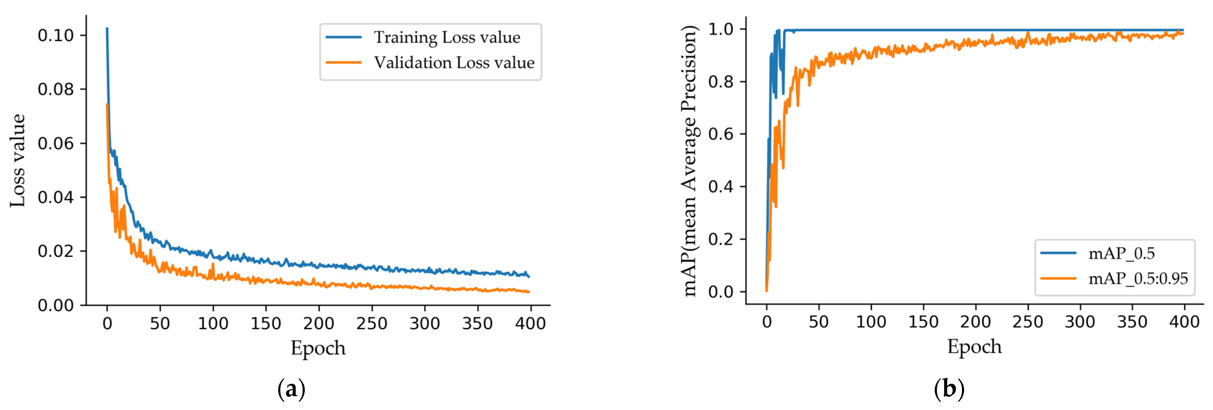
Figure 4a shows the training loss curves, which decrease rapidly in the first 50 epochs and stabilize after 200 epochs. The mAP (mean Average Precision) of the validation set is shown in Figure 4b. When the IoU (Intersection over Union) threshold is set to 0.5, mAP stabilizes at a high value (fixed at 0.995) after 30 epochs. When the threshold is set from 0.5 to 0.95, the average mAP is stabilized at a high value after 300 epochs. The proposed method uses the best weights after 300 epochs for object detection. It should be noted that the training is easy because the network is not trained from scratch, and the dataset is small compared to COCO.
2.4. Generation of Partial Point Cloud
As shown in Part II in Figure 1, the method is divided into object detection, generation of the partial point cloud, and ICP.
The RGB image captured by HoloLens2 is used to determine the object’s bounding box by YOLOv5s, represented by four values (x, y, w, h). (x, y) is the center coordinate of the bounding box, and (w, h) is the width and height of the bounding box.
The resolution of the RGB image acquired by HoloLens2 is and the resolution of the depth image is . The field of view of the two datasets differs significantly, so the two images need to be aligned. The point cloud corresponding to the depth image can be obtained according to intrinsic parameters. Assume that the coordinate of the point in the depth coordinate system is , which is calculated as
where is the pixel coordinate corresponding to the point in the depth image, is the depth of , and represents the intrinsic parameter of the depth camera. From the transformation of the RGB camera coordinate system relative to the depth camera coordinate system, the spatial point coordinates can be calculated as
where is the transformation of the depth camera coordinate system relative to the RGB camera coordinate system. Since , the pixel coordinates on the RGB image can be calculated as follows:
where is the depth of in the RGB camera coordinate system. By combining Equations (5) and (7), it can be calculated as follows:
In practice, we align RGB images to depth images through Equation (8). Then, corresponding pixel coordinates of the bounding box on the depth image can be determined. Furthermore, we obtain the point cloud according to Equation (5). It should be noted that the point cloud is generated by the single-view depth image, which only expresses partial information about the object and is called the partial point cloud. As shown in Figure 5, the point cloud is incomplete where the camera cannot capture the whole structure due to obstruction.
2.5. Pose Estimation
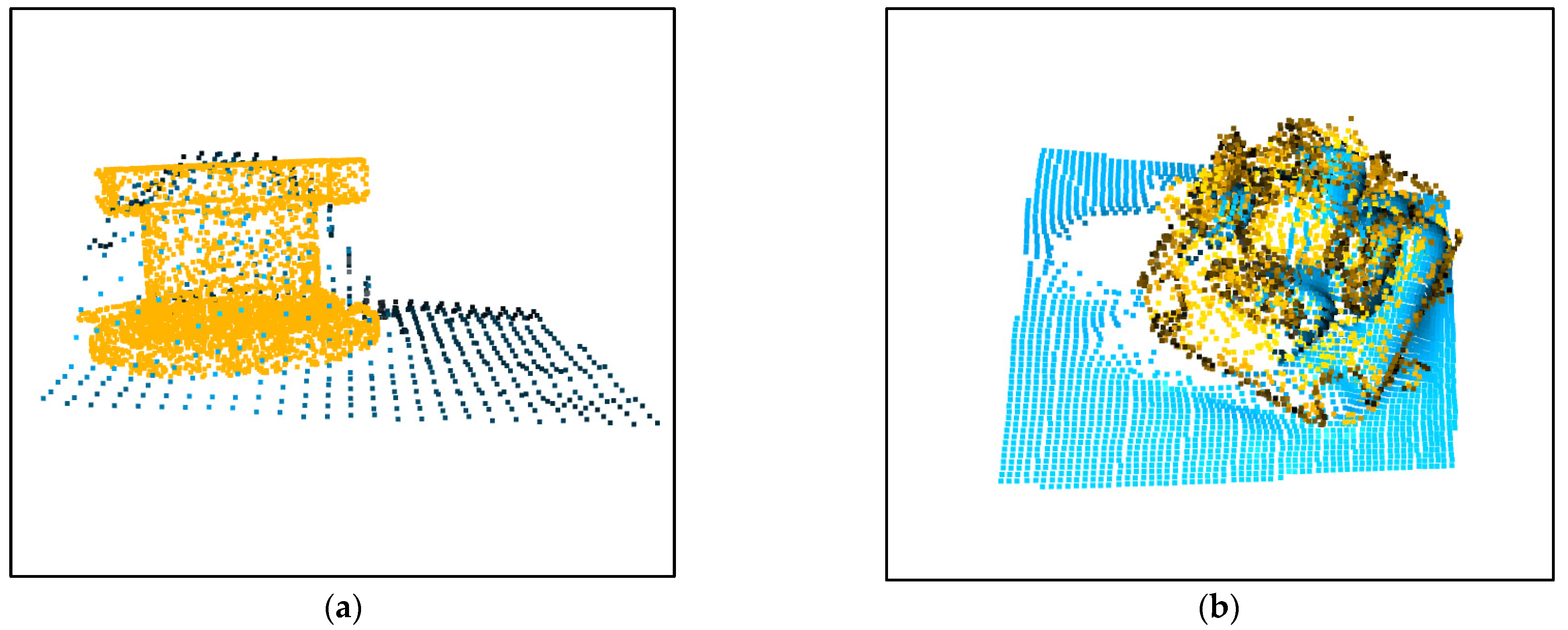
The template point cloud is obtained from the manually created CAD model by sampling, as shown in Figure 6. The partial point cloud is aligned with the template point cloud by ICP to calculate the transformation between them. The commonly used ICP algorithms are divided into the point-point algorithm [34] and the point-plane algorithm [38], and the point-plane algorithm converges faster. However, it is found in the experiments that the results calculated by the point-plane algorithm often fail. The reason may be that point clouds in this method are too noisy and non-homologous. Additional errors are introduced in determining the plane where the points are located, which is not as good as directly calculating the distance between matched pairs of points. The ICP method used in this method is as follows.
Given point clouds and , we define the target function:
equivalent to
Among them,
P is the template point cloud, and Q means the partial point cloud. T denotes the transformation matrix between point clouds, including the rotation R and the translation t. is the kernel function to limit the influence of outer points. Then, the pose between point clouds can be calculated by minimizing Equation (10). In practice, fast global registration (FGR) [39] is used to obtain the initial transformation.
The results of the point cloud alignment are shown in Figure 7. Although the appearance of the two point clouds is different, the alignments are approximately accurate.
3. Results and Discussion
A fixed valve and a movable panoramic camera are selected as detected objects to verify the method’s performance. Given that the MR ultimately provides operational guidance to humans, human experience in the task is essential. Twenty subjects are invited to experience HoloLens2 and give feedback on whether the algorithm is useful through questionnaires. The experiments show that the proposed method can project virtual information with fixed or movable objects, proving the usability and usefulness of the method.
3.1. Results of Object Detection
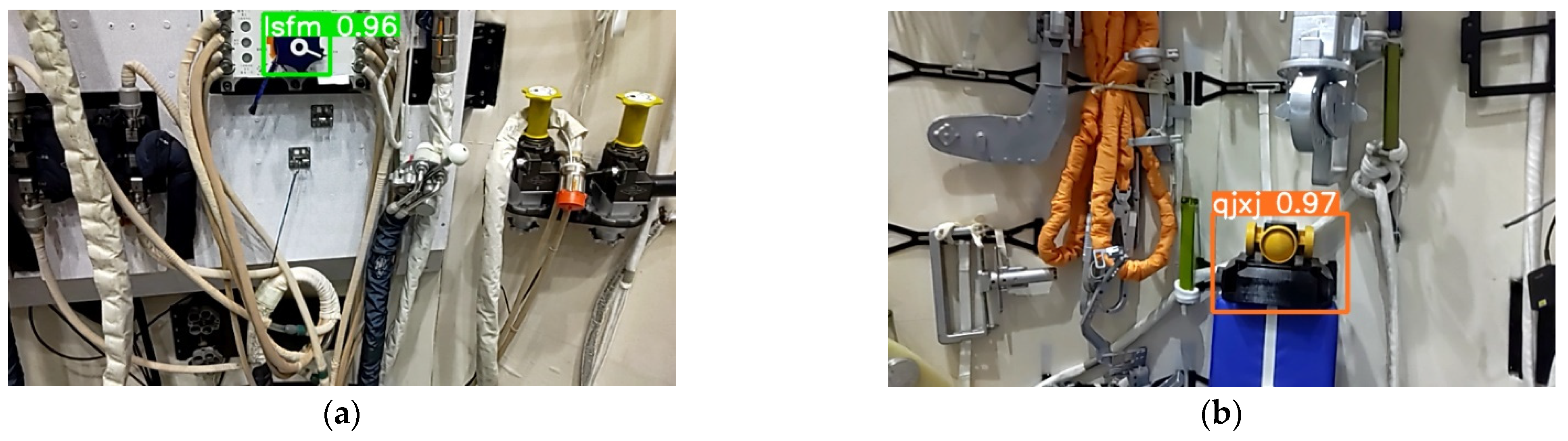
After 100 images were tested, the average processing time for each image was 0.0102 s, including 0.0005 s for preprocessing, 0.0082 s for inference, and 0.0015 s for NMS (non-maximum suppression). Compared with the data transfer rate between HoloLens2 and the server, the object detection time is negligible, so the operation of the whole system can be well satisfied.
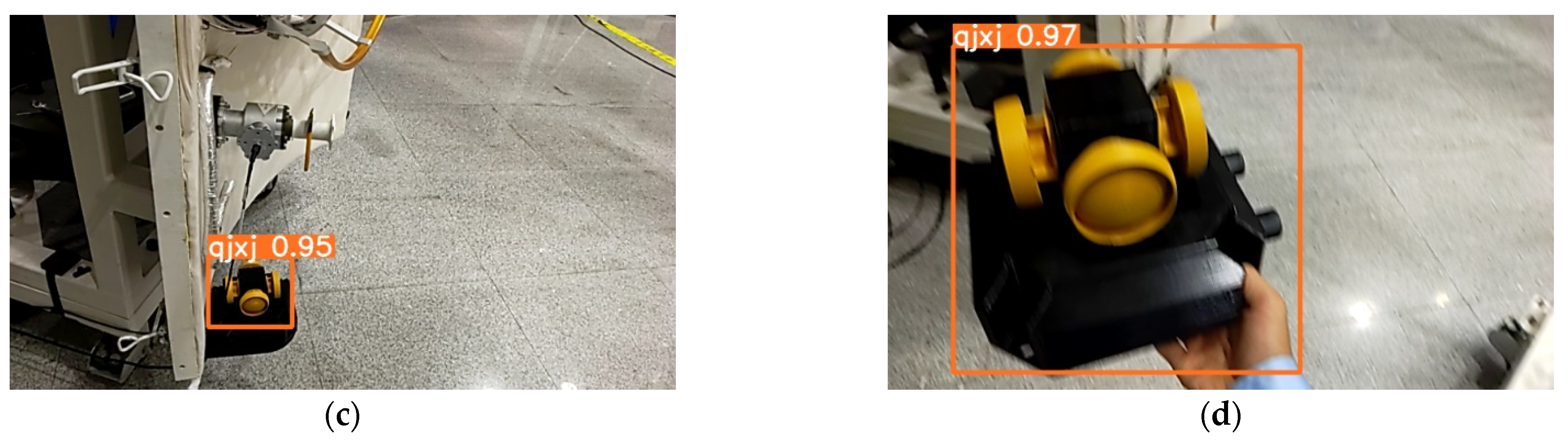
Compared to work dedicated to object detection, it does not make sense for us to verify the accuracy of the network on a test dataset. This is because the test set of our application scene is similar to the training set, which is evident in the training phase of the network. The detection results saved during the whole system’s real-time operation are shown in Figure 8. Figure 8a is the result of a fixed valve, Figure 8b,c are results of a fixed panoramic camera, and Figure 8d is the result of a moving panoramic camera. It can be seen from Figure 8d that the network accurately detects the object even if the captured image is blurred while on the move. The images sent from HoloLens2 to the server were all detected correctly.
3.2. MR Applications for the Static Object
The experimental object is a valve fixed to the cabin. In astronaut training, it is usually necessary to operate similar objects. The astronauts could be guided to perform the correct operation with added virtual information. This is particularly important in space–ground communication, where the information had by astronauts in orbit and experts on the ground is not equivalent. Astronauts in space will be less sensitive to orientation for various unique reasons, so MR assistance is especially needed.
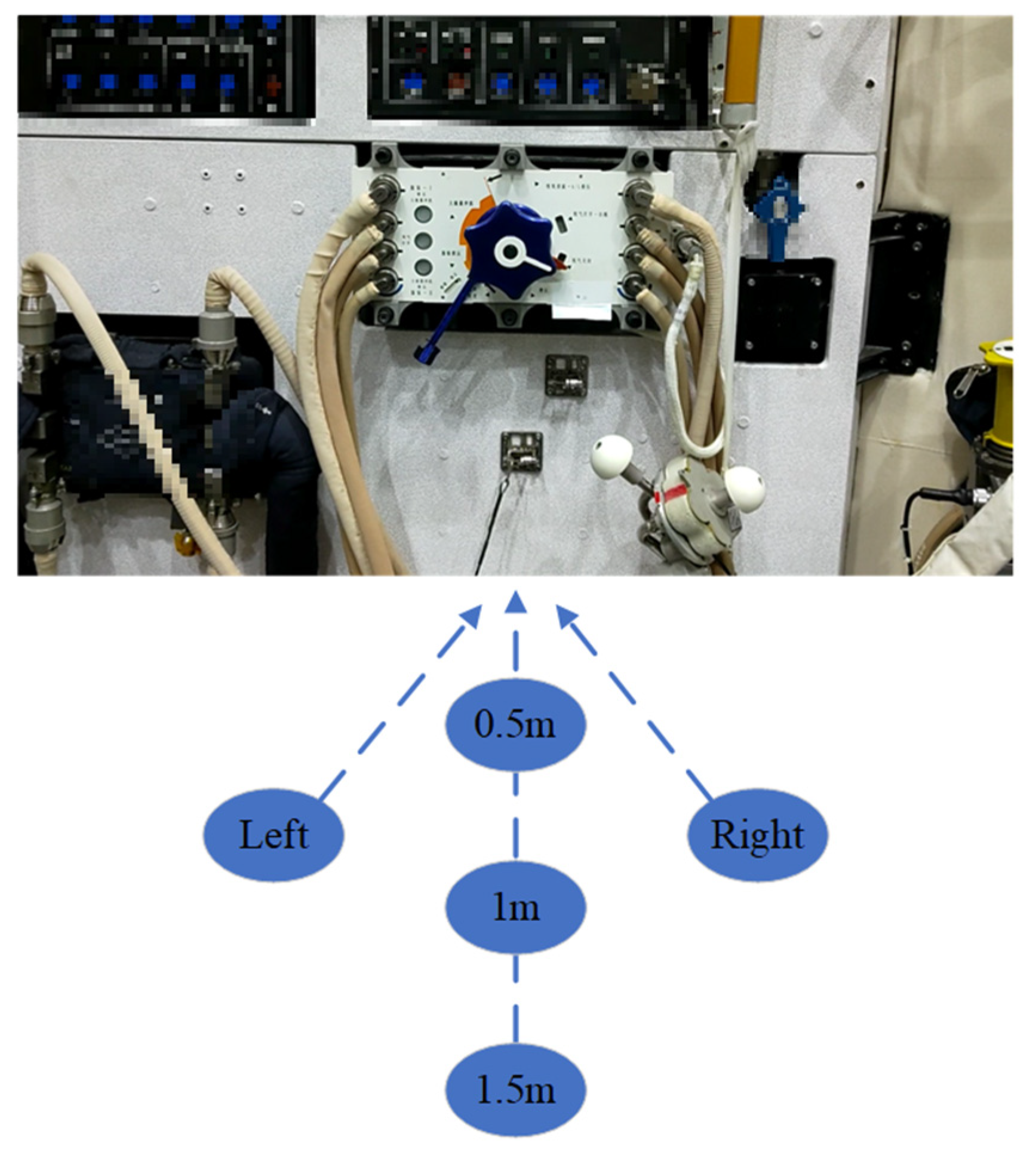
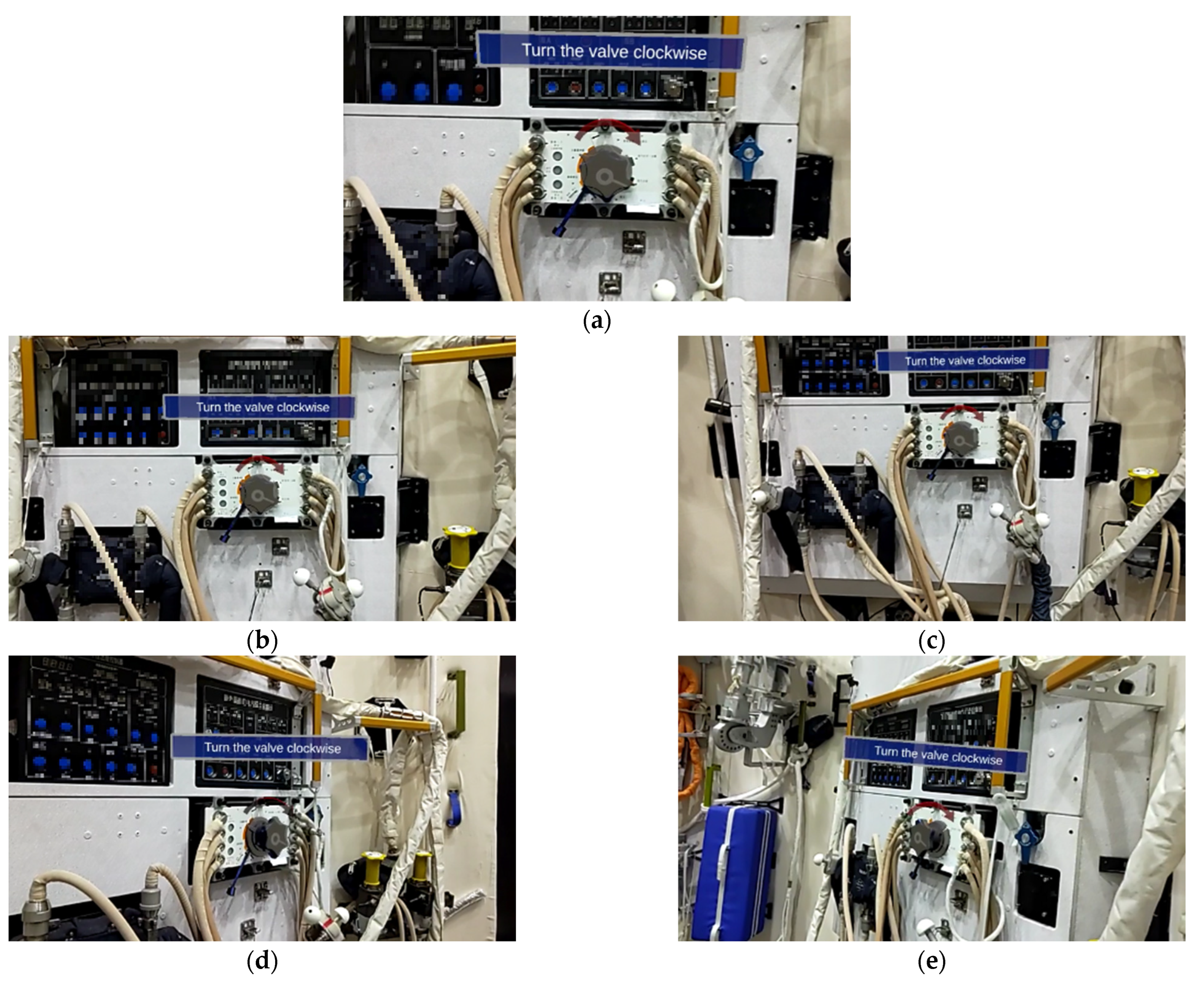
The marker-based approach is more sensitive to distance [32]. For comparison, a valve is observed at different distances and angles to verify the proposed method, as shown in Figure 9. Due to the spacecraft cabin structure limitation, the experiment performs the observation at distances of 0.5 m, 1 m, and 1.5 m, respectively. Furthermore, we change the observation angle at the fixed distance of 1 m.
Figure 10 shows the results of our algorithm at each point. It can be seen that the virtual–real fusion is good when facing the object regardless of the distance change. However, it must be noted that the virtual–real matching worsens when the observation angle changes. Because the object’s front surface is contoured, the observation is complete. In comparison, the brim is incomplete when the occlusion occurs from the rotation. Astronauts generally face the object during operation, so the inaccuracy of the lateral pose will not affect the task result.
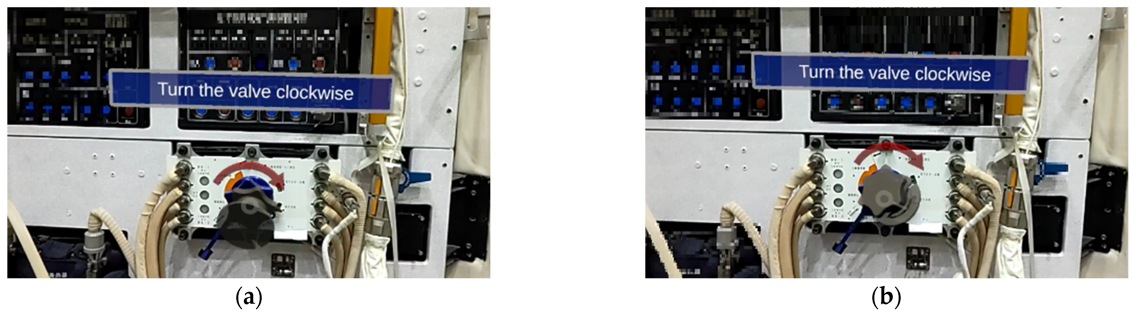
The most similar method to ours is [33]. Figure 11 shows the results using the algorithm proposed in [33]. To be clear, our results are all screenshots of HoloLens 2 running in real-time. Therefore, they do not coincide with the viewing angles in Figure 10. As can be seen, it is hard to get accurate results. For [28], the subjects were large-sized objects with a simple background. By contrast, our object size is small, and the environment is more complex. So, our method is more suitable for astronaut training.
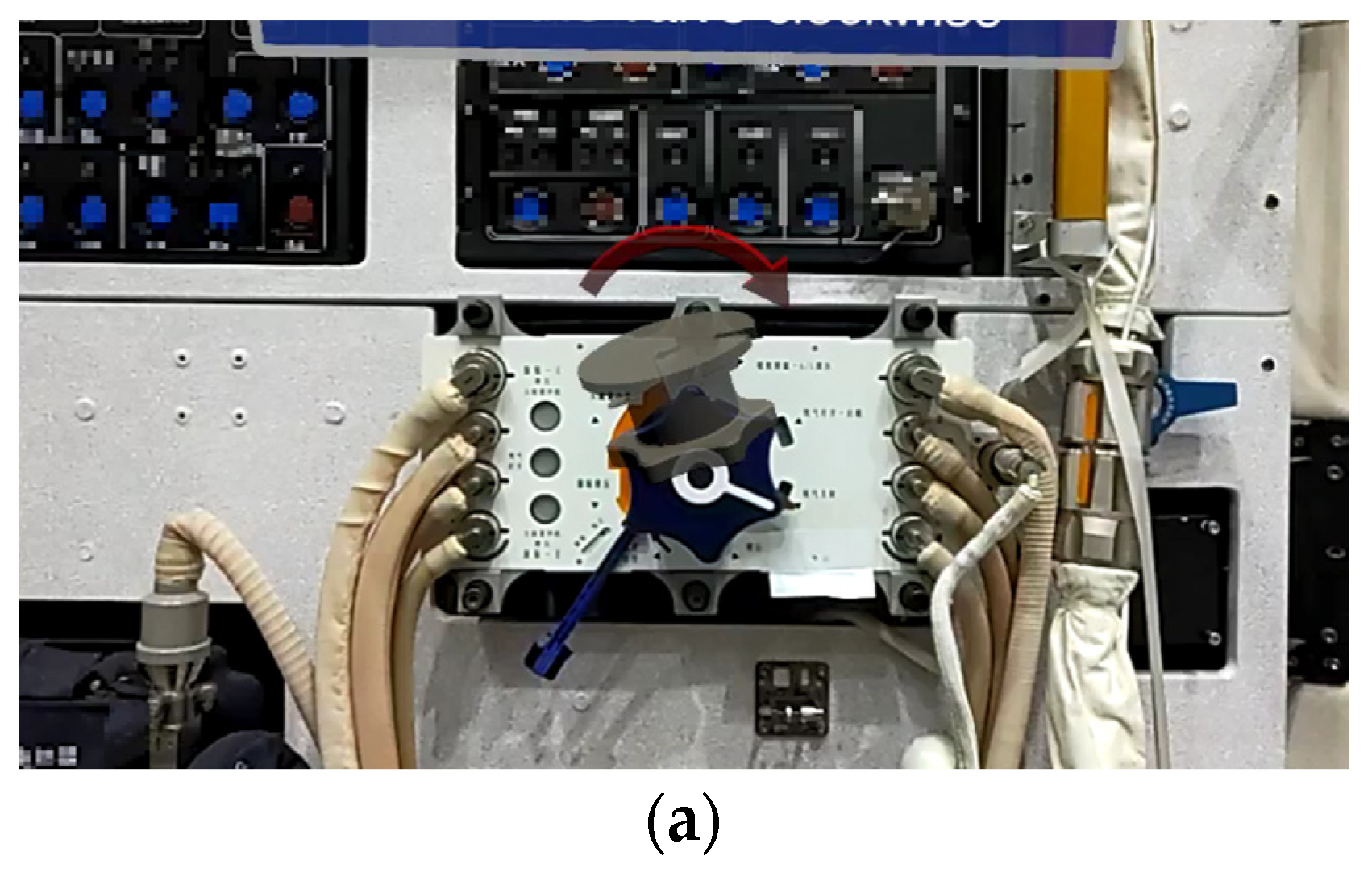
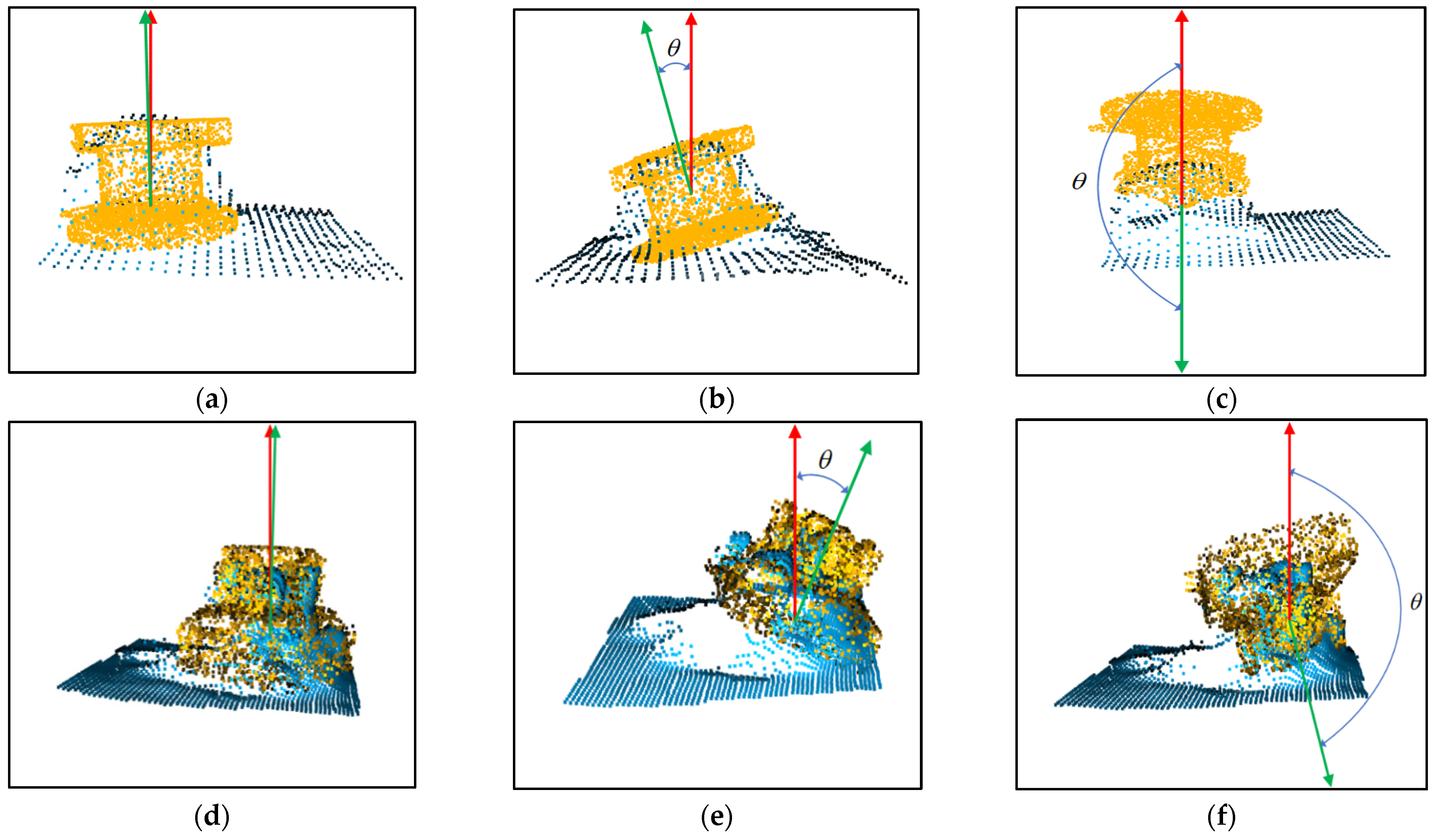
In particular, during the experiment, the virtual-real registration is ineffective in some cases. As shown in Figure 12, the axis of symmetry of the virtual valve differs from that of the real object. The cause is the different depth data from different bounding boxes, which results in the difference in ICP. To solve this problem, two methods are proposed.
3.2.1. Filtering Results of the Pose
The pose is sent to HoloLens2 only when the angle between the symmetry axis of the hologram and the symmetry axis of the real object does not exceed the threshold. The previous pose is always used until the new pose is received, and the threshold is set to 5°. Therefore, helpful results will always be displayed during the device’s operation. Various results are shown in Figure 13. The angle between the symmetry axis of the template point cloud (green) and the symmetry axis of the partial point cloud (red) is . In practice, the results with less than the threshold are selected and sent to HoloLens2 for display.
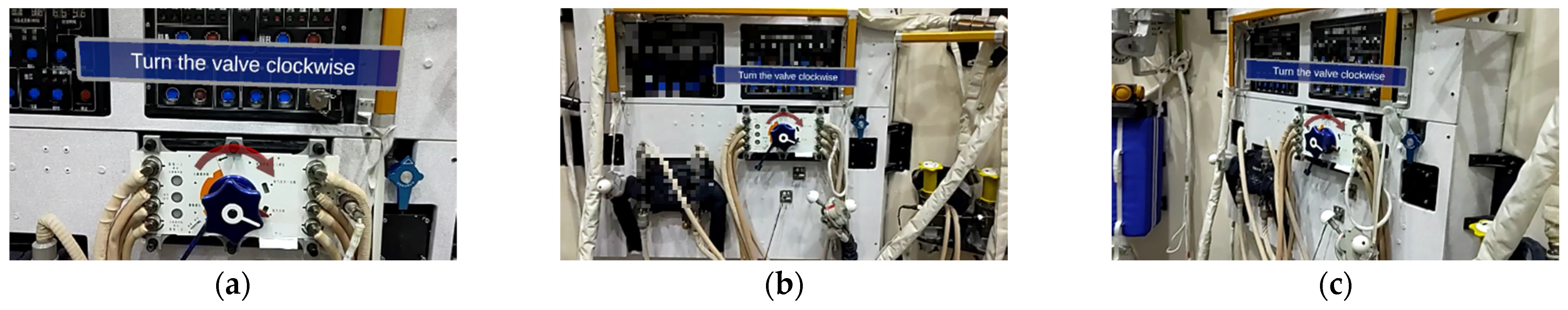
3.2.2. Only the Translation Is Calculated
During the ICP, we find that the translation is calculated robustly. However, the rotation error is relatively large. The virtual arrow (red) and text in Figure 14 are artificially set to rotate with the line of sight (always directly in the line of sight) and are fixed relative to the valve. Therefore, it is necessary to know the translation of the valve only to determine the position of the virtual arrow and the text, not to precisely calculate the rotation of the valve.
Figure 14 shows the results of using this method and hiding the valve. There may be errors in the rotation of the virtual valve calculated by ICP. While the translation is more accurate, the red arrows and the text can always be displayed correctly without rotation. Astronaut training primarily includes process tasks. Specifically, tips on the operation are required, but not frequent registration of real and virtual objects. Therefore, our method can meet the task needs.
3.3. MR Applications for the Movable Object
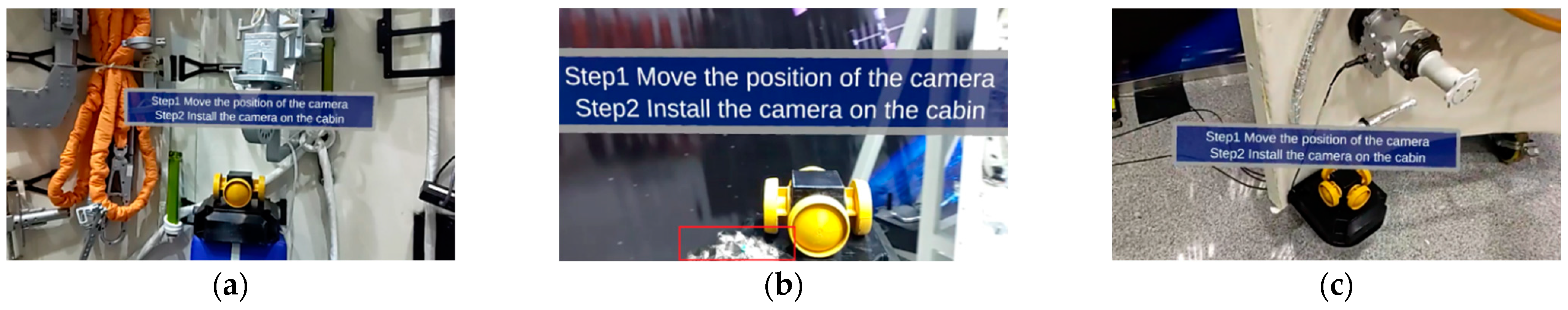
Moving positions and performing operations on objects are necessary for some training, such as assembling equipment. A typical task is moving the panoramic camera in astronaut extravehicular activities. Conventional MR only performs localization by the marker or background and does not work when the object moves to a new location. To address this issue, a panoramic camera is used in the experiment. Figure 15a shows the result of virtual-real registration in scene 1, and the text is accurately displayed above the panoramic camera. The panoramic camera is moved to different scenes, and Figure 15b shows the moving process. As shown in Figure 15c, when the panoramic camera appears again in a different field of view, the virtual information can be quickly matched on the real object. Experiments show that the proposed method does not depend on any background and does not require any fixed reference to be preset. The registration can be performed as long as the object is detected in the field of view.
3.4. Feedback from Subjects
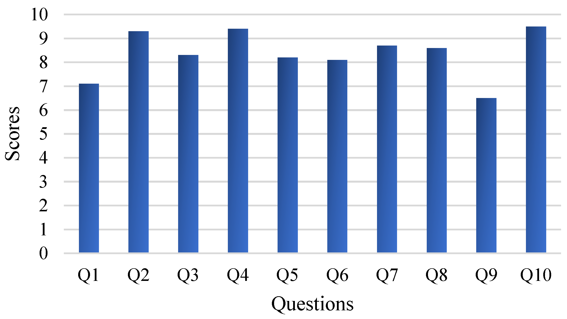
MR is ultimately used to assist astronauts, so the human experience is significant. Fifteen subjects (seven men and eight women, with an average age of 30.2 years) are invited to the experiment. Among them, five have MR development experience, another five have no development experience but do have experience in MR applications, and the other five do not have access to MR equipment. Subjects are asked to wear HoloLens2 and are allowed to move around to observe the fixed object. Then, the panoramic camera can be carried to other sites at will so the subject can experience the method’s performance with a movable object. After the experiment, each subject must finish a questionnaire consisting of 10 questions, as shown in Table 2, several of which are acquired from [33]. Each question has a score of 10. A higher score indicates that the proposed method is more effective, and the average score for each question is calculated to assess the method’s performance.
Figure 16 shows the results of the questionnaires (averaged). There is a consensus that this method is better when applied to movable objects, especially for those with experience in MR development. Because the traditional method generally applies to static environments, where markers or spatial anchors are preset in advance, it cannot be used for movable objects. While in the static task, subjects who do not have access to MR have a positive experience, other subjects do not see much improvement over the traditional method. Results are sometimes inferior to the traditional method in terms of pose accuracy. This is because the traditional method can manually preset the virtual object and precisely adjust the poses according to human observation.
In contrast, achieving precise results in our method is difficult due to the quality of the point cloud and the alignment error. The same issue is reflected in Q5 and Q6, where some subjects encountered poor pose accuracy during the experiment. Indeed, the pose estimation is performed in real-time. The quality of the partial point clouds obtained at different angles will lead to different pose accuracy. Although two methods are adopted to correct this problem, the accuracy is still inadequate compared to markers or spatial anchors.
Some subjects feel that precise alignment of the virtual object with the real object is not very helpful for the task and that only text is needed to satisfy the requirements, as reflected in Q3 and Q4. This is because the task focuses on affecting the operational process and does not require precise guidance to perform delicate operations on the object. At the same time, the proposed method makes it difficult to precisely match the virtual object with the real object. The text, on the other hand, only needs to calculate the translation of the real object, so more subjects prefer to use the procedure without the virtual object. Q7 and Q8 are mainly reflected in the setting of virtual information, which has little relationship to pose accuracy. Our method adds text for information enhancement, which is more robust with pose accuracy. The LAN limits the data transmission rate to 3 fps, so there is a delay when the object is moved to a new location. Therefore, some subjects feel that the real-time performance is unsatisfactory, which is reflected in Q9.
In summary, most subjects approve of our system and consider it a meaningful attempt. There is still room for improvement, especially regarding pose accuracy. Of course, this needs to be accomplished through other methods. Methods based on deep learning and point cloud alignment are inherently uncertain, and it is challenging to achieve the same accuracy with them as it is with manual fine-tuning.
4. Conclusions
A method based on object detection and point cloud alignment is proposed for task assistance in astronaut MR training. For the weak texture features, small object size, and irregular configuration, YOLOv5s is used to detect the object’s bounding box on RGB images. Furthermore, depth images are combined to segment the object’s partial point cloud. Then, the partial point cloud is aligned with the template point cloud using ICP, where the template point cloud is obtained by sampling from the CAD model. The proposed method does not rely on any pre-determined spatial information. It automatically estimates the pose of fixed or movable objects, expanding the forms of MR training for astronauts.
Experiments are performed for fixed and movable objects, respectively. Specifically, virtual information can be accurately projected onto fixed objects and does not depend on anchors. For the movable object, the virtual information can follow the object, which improves the flexibility of MR training. Moreover, the subject experience shows that the proposed method has better value for movable objects. However, the accuracy of virtual-real alignment is not improved. For future work, different technologies or devices need to be used to enable higher pose accuracy and faster data transmission.
Author Contributions
Conceptualization, Q.S. and J.C.; methodology, Q.S., R.C. and W.C.; validation, Q.S. and R.C.; investigation, Z.X. and W.C.; writing—original draft preparation, Q.S.; writing—review and editing, J.C., Z.X. and W.L.; visualization, Q.S. and W.L.; supervision, J.C.; funding acquisition, W.L., W.C. and J.C. All authors have read and agreed to the published version of the manuscript.
Funding
This research was funded by the Work Enhancement Based on Visual Scene Perception and the National Key Laboratory Foundation of Human Factor Engineering [grant numbers 6142222200403, SYFD062003].
Institutional Review Board Statement
Not applicable.
Informed Consent Statement
Not applicable.
Data Availability Statement
Due to the policy of the affiliation, data sharing is not applicable to this article.
Conflicts of Interest
The authors declare no conflict of interest.
References
- Chang, L.; Jiangang, C.; Ning, H.; Wei, C.; Zhenying, X. Research on Scene Understanding Method in Mixed Reality for Astronaut Training. Manned Spacefl. 2020, 26, 26–33. [Google Scholar] [CrossRef]
- Qingwei, S.; Jiangang, C.; Wei, C.; Jin, Y.; Wanhong, L.; Zhenying, X.; Hongbo, Z. 3D Semantic Reconstruction of Spacecraft Cabin Structures. Manned Spacefl. 2021, 27, 72–80. [Google Scholar] [CrossRef]
- Vuforia Chalk. Available online: https://chalk.vuforia.com (accessed on 23 April 2023).
- Zheng, L.; Liu, X.; An, Z.; Li, S.; Zhang, R. A smart assistance system for cable assembly by combining wearable augmented reality with portable visual inspection. Virtual Real. Intell. Hardw. 2020, 2, 12–27. [Google Scholar] [CrossRef]
- Nee, A.Y.C.; Ong, S.K.; Chryssolouris, G.; Mourtzis, D. Augmented reality applications in design and manufacturing. CIRP Ann. 2012, 61, 657–679. [Google Scholar] [CrossRef]
- Microsoft. Azure Spatial Anchors. Available online: https://learn.microsoft.com/en-us/azure/spatial-anchors/ (accessed on 9 May 2022).
- Lee, J.Y.; Rhee, G.W.; Park, H. AR/RP-based tangible interactions for collaborative design evaluation of digital products. J. Adv. Manuf. Technol. 2009, 45, 649–665. [Google Scholar] [CrossRef]
- Egger, J.; Masood, T. Augmented reality in support of intelligent manufacturing—A systematic literature review. Comput Ind. Eng. 2020, 140, 106195. [Google Scholar] [CrossRef]
- Girshick, R.; Donahue, J.; Darrell, T.; Malik, J. Rich Feature Hierarchies for Accurate Object Detection and Semantic Segmentation. In Proceedings of the 2014 IEEE Conference on Computer Vision and Pattern Recognition (CVPR), Columbus, OH, USA, 23–28 June 2014; pp. 580–587. [Google Scholar]
- He, K.; Zhang, X.; Ren, S.; Sun, J. Spatial Pyramid Pooling in Deep Convolutional Networks for Visual Recognition. IEEE Trans. Pattern Anal. Mach. Intell. 2015, 37, 1904–1916. [Google Scholar] [CrossRef] [PubMed]
- Girshick, R. Fast R-CNN. In Proceedings of the 2015 IEEE International Conference on Computer Vision (ICCV), Santiago, Chile, 7–13 December 2015; pp. 1440–1448. [Google Scholar]
- Ren, S.; He, K.; Girshick, R.; Sun, J. Faster R-CNN: Towards Real-Time Object Detection with Region Proposal Networks. IEEE Trans. Pattern Anal. Mach. Intell. 2017, 39, 1137–1149. [Google Scholar] [CrossRef] [PubMed]
- He, K.; Gkioxari, G.; Dollár, P.; Girshick, R. Mask R-CNN. In Proceedings of the IEEE International Conference on Computer Vision, Venice, Italy, 22–29 October 2017; pp. 2980–2988. [Google Scholar]
- Redmon, J.; Divvala, S.; Girshick, R.; Farhadi, A. You Only Look Once: Unified, Real-Time Object Detection. In Proceedings of the 2016 IEEE Conference on Computer Vision and Pattern Recognition (CVPR), Las Vegas, NV, USA, 27–30 June 2016; pp. 779–788. [Google Scholar]
- Redmon, J.; Farhadi, A. YOLO9000: Better, Faster, Stronger. In Proceedings of the 2017 IEEE Conference on Computer Vision and Pattern Recognition (CVPR), Honolulu, HI, USA, 21–26 July 2017; pp. 6517–6525. [Google Scholar]
- Redmon, J.; Farhadi, A. YOLOv3: An Incremental Improvement. arXiv 2018, arXiv:1804.02767. [Google Scholar]
- Bochkovskiy, A.; Wang, C.-Y.; Liao, H.-Y.M. YOLOv4: Optimal Speed and Accuracy of Object Detection. arXiv 2020, arXiv:2004.10934. [Google Scholar]
- Liu, W.; Anguelov, D.; Erhan, D.; Szegedy, C.; Reed, S.; Fu, C.-Y.; Berg, A.C. SSD: Single Shot MultiBox Detector. In Proceedings of the 2016 European Conference on Computer Vision (ECCV), Amsterdam, The Netherlands, 11–14 October 2016; pp. 21–37. [Google Scholar]
- Ultralytics. Yolov5. Available online: https://github.com/ultralytics/yolov5 (accessed on 10 March 2022).
- Tekin, B.; Sinha, S.N.; Fua, P. Real-Time Seamless Single Shot 6D Object Pose Prediction. In Proceedings of the 2018 IEEE/CVF Conference on Computer Vision and Pattern Recognition (CVPR), Salt Lake City, UT, USA, 18–23 June 2018; Leibe, B., Matas, J., Sebe, N., Welling, M., Eds.; Springer International Publishing: Amsterdam, The Netherlands, 2016; pp. 292–301. [Google Scholar]
- Rad, M.; Lepetit, V. BB8: A Scalable, Accurate, Robust to Partial Occlusion Method for Predicting the 3D Poses of Challenging Objects without Using Depth. In Proceedings of the 2017 IEEE International Conference on Computer Vision (ICCV), Venice, Italy, 22–29 October 2017; pp. 3848–3856. [Google Scholar]
- Rad, M.; Oberweger, M.; Lepetit, V. Feature Mapping for Learning Fast and Accurate 3D Pose Inference from Synthetic Images. In Proceedings of the 2018 IEEE/CVF Conference on Computer Vision and Pattern Recognition (CVPR), Salt Lake City, UT, USA; 2018; pp. 4663–4672. [Google Scholar]
- Rusu, R.B.; Blodow, N.; Beetz, M. Fast Point Feature Histograms (FPFH) for 3D registration. In Proceedings of the 2009 IEEE International Conference on Robotics and Automation (ICRA), Kobe, Japan, 12–17 May 2009; pp. 3212–3217. [Google Scholar]
- Dong, Z.; Yang, B.; Liu, Y.; Liang, F.; Li, B.; Zang, Y. A novel binary shape context for 3D local surface description. ISPRS J. Photogramm. Remote Sens. 2017, 130, 431–452. [Google Scholar] [CrossRef]
- Hodaň, T.; Zabulis, X.; Lourakis, M.; Obdržálek, Š.; Matas, J. Detection and fine 3D pose estimation of texture-less objects in RGB-D images. In Proceedings of the 2015 IEEE/RSJ International Conference on Intelligent Robots and Systems (IROS), Hamburg, Germany, 28 September–2 October 2015; pp. 4421–4428. [Google Scholar]
- Hinterstoisser, S.; Lepetit, V.; Ilic, S.; Holzer, S.; Bradski, G.; Konolige, K.; Navab, N. Model based training, detection and pose estimation of texture-less 3D objects in heavily cluttered scenes. In Proceedings of the 11th Asian Conference on Computer Vision (ACCV), Daejeon, Korea, 5–9 November 2012; pp. 548–562. [Google Scholar]
- Aoki, Y.; Goforth, H.; Srivatsan, R.A.; Lucey, S. PointNetLK: Robust & Efficient Point Cloud Registration Using PointNet. In Proceedings of the 2019 IEEE/CVF Conference on Computer Vision and Pattern Recognition (CVPR), Long Beach, CA, USA, 15–20 June 2019; pp. 7156–7165. [Google Scholar]
- Sarode, V.; Li, X.; Goforth, H.; Aoki, Y.; Srivatsan, R.A.; Lucey, S.; Choset, H. PCRNet: Point cloud registration network using PointNet encoding. arXiv 2019, arXiv:1908.07906. [Google Scholar]
- Peng, S.; Zhou, X.; Liu, Y.; Lin, H.; Huang, Q.; Bao, H. PVNet: Pixel-Wise Voting Network for 6DoF Object Pose Estimation. IEEE Trans. Pattern Anal. Mach. Intell. 2022, 44, 3212–3223. [Google Scholar] [CrossRef] [PubMed]
- He, Y.; Sun, W.; Huang, H.; Liu, J.; Fan, H.; Sun, J. PVN3D: A deep point-wise 3D keypoints voting network for 6DoF pose estimation. In Proceedings of the 2020 IEEE/CVF Conference on Computer Vision and Pattern Recognition (CVPR), Seattle, WA, USA, 14–19 June 2020; pp. 11629–11638. [Google Scholar]
- Wang, C.; Martín-Martín, R.; Xu, D.; Lv, J.; Lu, C.; Fei-Fei, L.; Savarese, S.; Zhu, Y. 6-PACK: Category-level 6D Pose Tracker with Anchor-Based Keypoints. In Proceedings of the 2020 IEEE International Conference on Robotics and Automation (ICRA), Paris, France, 31 May–31 August 2020; pp. 10059–10066. [Google Scholar]
- Park, K.-B.; Kim, M.; Choi, S.H.; Lee, J.Y. Deep learning-based smart task assistance in wearable augmented reality. Robot Comput. Integr. Manuf. 2020, 63, 101887. [Google Scholar] [CrossRef]
- Park, K.-B.; Choi, S.H.; Kim, M.; Lee, J.Y. Deep learning-based mobile augmented reality for task assistance using 3D spatial mapping and snapshot-based RGB-D data. Comput Ind. Eng. 2020, 146, 106585. [Google Scholar] [CrossRef]
- Besl, P.J.; McKay, N.D. A method for registration of 3-D shapes. IEEE Trans. Pattern Anal. Mach. Intell. 1992, 14, 239–256. [Google Scholar] [CrossRef]
- Ungureanu, D.; Bogo, F.; Galliani, S.; Sama, P.; Duan, X.; Meekhof, C.; Stühmer, J.; Cashman, T.J.; Tekin, B.; Schönberger, J.L.; et al. HoloLens 2 Research Mode as a Tool for Computer Vision Research. arXiv 2020, arXiv:2008.11239. [Google Scholar]
- Eberly, D. Conversion of Left–Handed Coordinates to Right–Handed Coordinates. Available online: https://www.docin.com/p-763518275.html (accessed on 13 July 2022).
- He, K.; Zhang, X.; Ren, S.; Sun, J. Deep Residual Learning for Image Recognition. In Proceedings of the IEEE Conference on Computer Vision and Pattern Recognition, Las Vegas, NV, USA, 27–30 June 2016; pp. 770–778. [Google Scholar]
- Chen, Y.; Medioni, G. Object modeling by registration of multiple range images. In Proceedings of the 1991 IEEE International Conference on Robotics and Automation (ICRA), Sacramento, CA, USA, 9–11 April 1991; pp. 2724–2729. [Google Scholar]
- Zhou, Q.-Y.; Park, J.; Koltun, V. Fast Global Registration. In Proceedings of the 2016 European Conference on Computer Vision (ECCV), Amsterdam, The Netherlands, 11–14 October 2016; pp. 766–782. [Google Scholar]
Figure 1.
Structure of the proposed method. The method is divided into object detection, generation of the partial point cloud, and ICP.
Figure 1.
Structure of the proposed method. The method is divided into object detection, generation of the partial point cloud, and ICP.

Figure 2.
Coordinate systems used in the method.

Figure 3.
Some images used in our method. (a,b) are fixed objects; (c) is the movable object in scene 1; (d,e) are objects during movement; (f) is the movable object in scene 2.
Figure 3.
Some images used in our method. (a,b) are fixed objects; (c) is the movable object in scene 1; (d,e) are objects during movement; (f) is the movable object in scene 2.

Figure 4.
Training results. (a) Loss of training and validation; (b) mAP of validation dataset.

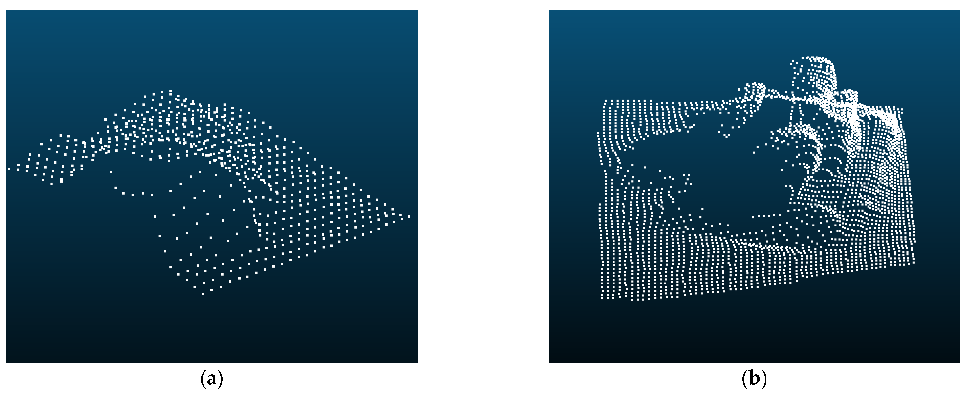
Figure 5.
Partial point cloud captured by HoloLens2. (a) Partial point cloud of the valve; (b) Partial point cloud of the panoramic camera.
Figure 5.
Partial point cloud captured by HoloLens2. (a) Partial point cloud of the valve; (b) Partial point cloud of the panoramic camera.

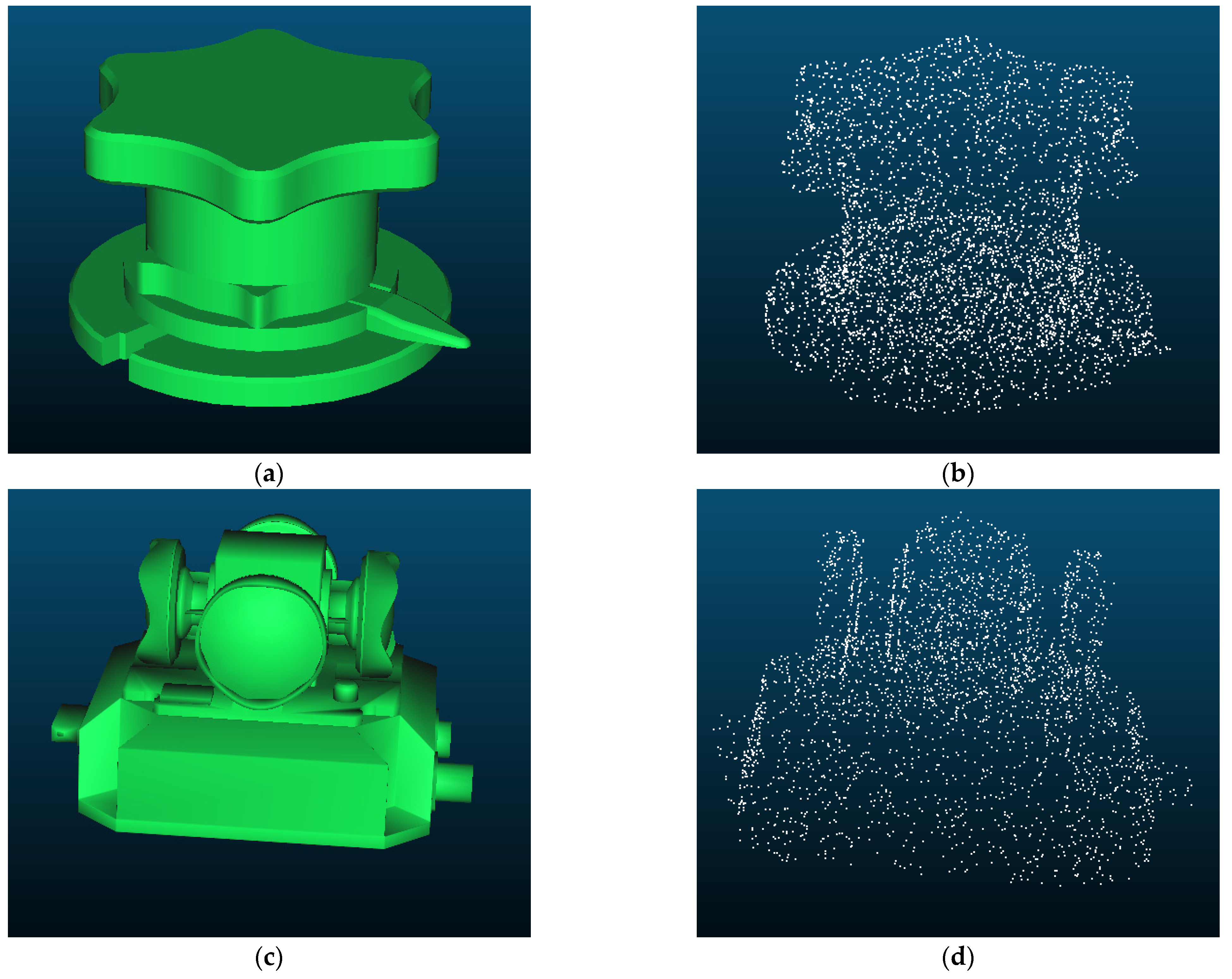
Figure 6.
Template point clouds in this method. (a) CAD model of a valve; (b) The template point cloud obtained by sampling the CAD model of the valve; (c) The CAD model of a panoramic camera; (d) The template point cloud obtained by sampling the CAD model of the panoramic camera.
Figure 6.
Template point clouds in this method. (a) CAD model of a valve; (b) The template point cloud obtained by sampling the CAD model of the valve; (c) The CAD model of a panoramic camera; (d) The template point cloud obtained by sampling the CAD model of the panoramic camera.

Figure 7.
Results of the point cloud alignment. (a) Results of the valve; (b) Results of the panoramic camera.
Figure 7.
Results of the point cloud alignment. (a) Results of the valve; (b) Results of the panoramic camera.

Figure 8.
Results using YOLOv5s. (a) Result of the valve (the label is set to lsfm); (b,c) Results of the fixed panoramic camera (the label is set to qjxj); (d) Result of the moving panoramic camera.
Figure 8.
Results using YOLOv5s. (a) Result of the valve (the label is set to lsfm); (b,c) Results of the fixed panoramic camera (the label is set to qjxj); (d) Result of the moving panoramic camera.


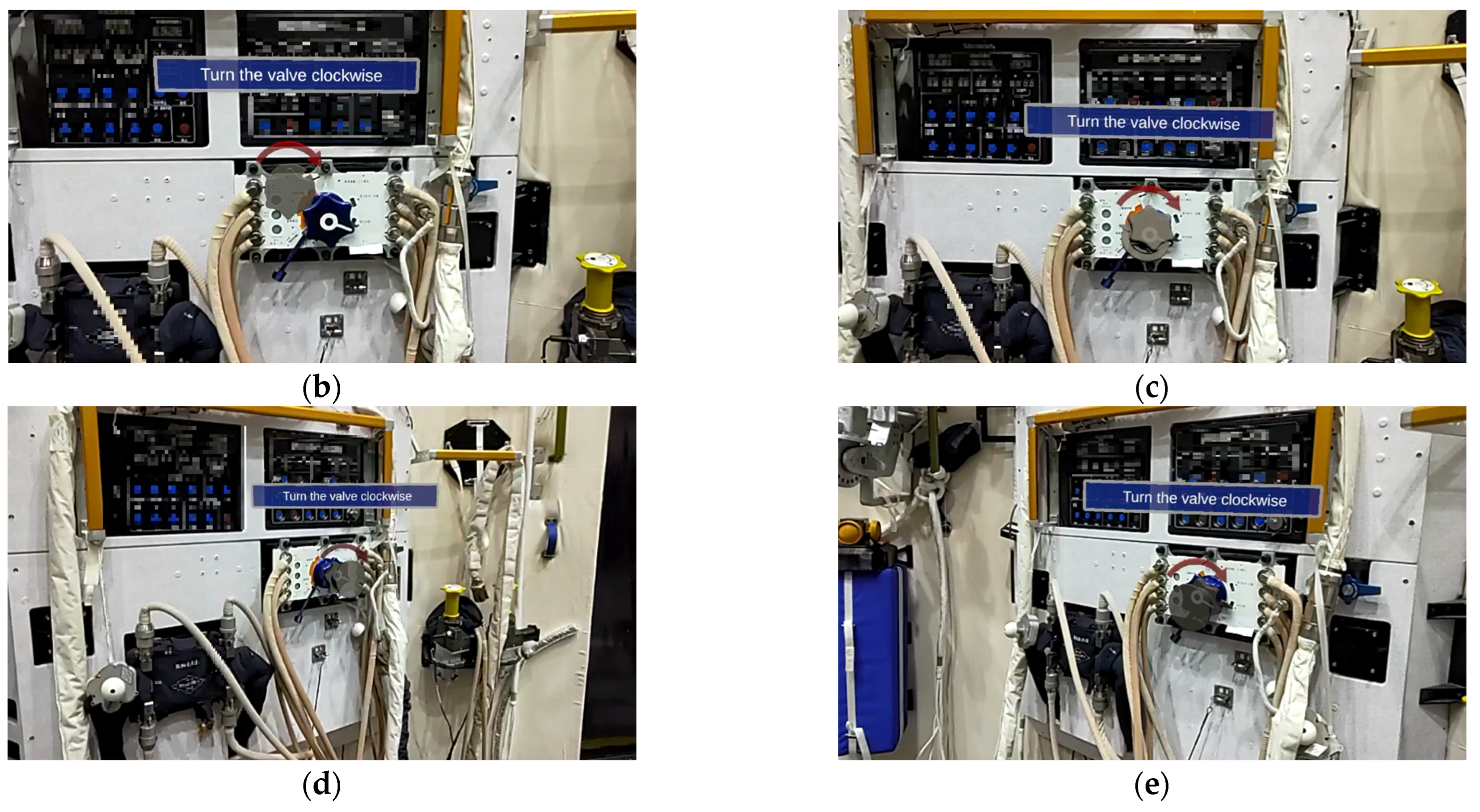
Figure 9.
Observe the object from different distances and angles.

Figure 10.
Results from different distances and angles of our method. (a) 0.5 m; (b) 1 m; (c) 1.5 m; (d) Left; (e) Right.
Figure 10.
Results from different distances and angles of our method. (a) 0.5 m; (b) 1 m; (c) 1.5 m; (d) Left; (e) Right.

Figure 11.
Results from different distances and angles of [33]. (a) 0.5 m; (b) 1 m; (c) 1.5 m; (d) Left; (e) Right.
Figure 11.
Results from different distances and angles of [33]. (a) 0.5 m; (b) 1 m; (c) 1.5 m; (d) Left; (e) Right.


Figure 12.
Some of the poor registration results. (a,b) are two poor registration results.

Figure 13.
Different results in the ICP. (a–c) Results of the valve; (d–f) Results of the panoramic camera.
Figure 13.
Different results in the ICP. (a–c) Results of the valve; (d–f) Results of the panoramic camera.

Figure 14.
Only the translation is calculated, and the virtual valve is hidden. (a–c) are results of different orientations.
Figure 14.
Only the translation is calculated, and the virtual valve is hidden. (a–c) are results of different orientations.

Figure 15.
Results for moving targets. (a) Scene 1; (b) During the movement (in the red rectangle is the hand recognition by HoloLens2); (c) Scene 2.
Figure 15.
Results for moving targets. (a) Scene 1; (b) During the movement (in the red rectangle is the hand recognition by HoloLens2); (c) Scene 2.

Figure 16.
Results of the questionnaires. Higher scores indicate that the proposed method is more useful.
Figure 16.
Results of the questionnaires. Higher scores indicate that the proposed method is more useful.


Table 1.
The learning environment for YOLOv5s.
| Environment | NVIDIA GeForce GTX 2060, Pytorch GPU, Intel i7-8750H |
| Network | YOLOv5s |
| Additional dataset | 400 images for each additional class |
| Pre-train dataset | COCO |
| Epochs | 400 |
| Learning rate | 0.0001 |
| Batch size | 4 |
Table 2.
Questionnaires for the proposed method.
| Simplified Questions | |
|---|---|
| Q1 | Like using this system on the fixed object |
| Q2 | Like using this system on the movable object |
| Q3 | Like using this system with virtual models and text |
| Q4 | Like using this system without virtual models |
| Q5 | Projected virtual information on the real object naturally |
| Q6 | Effective registration of real structure and virtual information |
| Q7 | Helpful for understanding structure operations |
| Q8 | It is easy to understand the meaning of virtual information |
| Q9 | The real-time performance of the method is acceptable |
| Q10 | It will be an effective method |
Disclaimer/Publisher’s Note: The statements, opinions and data contained in all publications are solely those of the individual author(s) and contributor(s) and not of MDPI and/or the editor(s). MDPI and/or the editor(s) disclaim responsibility for any injury to people or property resulting from any ideas, methods, instructions or products referred to in the content. |
© 2023 by the authors. Licensee MDPI, Basel, Switzerland. This article is an open access article distributed under the terms and conditions of the Creative Commons Attribution (CC BY) license (https://creativecommons.org/licenses/by/4.0/).
Share and Cite
MDPI and ACS Style
Sun, Q.; Chen, W.; Chao, J.; Lin, W.; Xu, Z.; Cao, R. Smart Task Assistance in Mixed Reality for Astronauts. Sensors 2023, 23, 4344. https://doi.org/10.3390/s23094344
AMA Style
Sun Q, Chen W, Chao J, Lin W, Xu Z, Cao R. Smart Task Assistance in Mixed Reality for Astronauts. Sensors. 2023; 23(9):4344. https://doi.org/10.3390/s23094344
Chicago/Turabian StyleSun, Qingwei, Wei Chen, Jiangang Chao, Wanhong Lin, Zhenying Xu, and Ruizhi Cao. 2023. "Smart Task Assistance in Mixed Reality for Astronauts" Sensors 23, no. 9: 4344. https://doi.org/10.3390/s23094344
Note that from the first issue of 2016, this journal uses article numbers instead of page numbers. See further details here.