
Lead-Free Piezoelectric Acceleration Sensor Built Using a (K,Na)NbO3 Bulk Ceramic Modified by Bi-Based Perovskites


Smart Sensing and Diagnosis Research Division, Korea Atomic Energy Research Institute, Daejeon 34057, Republic of Korea
*
Author to whom correspondence should be addressed.
Sensors 2023, 23(2), 1029; https://doi.org/10.3390/s23021029
Submission received: 8 December 2022
/
Revised: 10 January 2023
/
Accepted: 11 January 2023
/
Published: 16 January 2023
(This article belongs to the Section Electronic Sensors)
Abstract
:Piezoelectric accelerometers using a lead-free (K,Na)NbO3 (KNN) piezoceramic modified by a mixture of two Bi-based perovskites, Bi(Na,K,Li)ZrO3 (BNKLZ) and BiScO3 (BS), were designed, fabricated and characterized. Ring-shaped ceramics were prepared using a conventional solid-state reaction method for integration into a compression-mode accelerometer. A beneficial rhombohedral–tetragonal (R–T) phase boundary structure, especially enriched with T phase, was produced by modifying intrinsic phase transition temperatures, yielding a large piezoelectric charge coefficient d33 (310 pC/N) and a high Curie temperature Tc (331 °C). Using finite element analyses with metamodeling techniques, four optimum accelerometer designs were obtained with high magnitudes of charge sensitivity Sq and resonant frequency fr, as evidenced by two key performance indicators having a trade-off relation. Finally, accelerometer sensor prototypes based on the proposed designs were fabricated using the KNN-BNKLZ-BS ceramic rings, which exhibited high levels of Sq (55.1 to 223.8 pC/g) and mounted fr (14.1 to 28.4 kHz). Perfect charge-to-acceleration linearity as well as broad flat frequency ranges were achieved with excellent reliability. These outstanding sensing performances confirm the potential application of the modified-KNN ceramic in piezoelectric sensors.
1. Introduction
Although Pb(Zr,Ti)O3 (PZT)-based ceramics have dominated the commercial market of electronic components and devices, including various types of piezoelectric sensors, actuators and ultrasonic transducers [1], their high content of toxic lead (60 wt%) presents serious environmental concerns during preparation and disposal processes. Because there have been global considerations, laws and regulations, spreading from the European Union to many other parts of the world, strongly demanding the elimination of lead-based materials from all consumer items [2,3], there is a pressing need to develop lead-free piezoelectric devices using a viable alternative to PZT.
In efforts to develop nontoxic replacements, both extensive and intensive research activities have been devoted to identifying lead-free piezoceramics during the last couple of decades [4,5,6]. Among potential lead-free families, (K,Na)NbO3 (KNN)-based ceramics are, so far at least, widely considered to be promising candidates because of their large piezoelectric activity and high Curie temperature [7,8]. Since the work by Saito, et al. [9], great progress has been made in the physical properties and mechanisms of this material system by chemical doping. This progress has been so substantial that certain electrical properties of novel KNN compositions are comparable to or exceed those of PZT when the ceramics possess a certain phase boundary structure (e.g., rhombohedral–tetragonal (R–T) structure) [10,11,12,13,14]. Although this material system has shown great potential, no single lead-free composition has yet been proposed for piezoelectric devices or components with proven reliability to replace PZT ceramics.
In addition to developing novel materials, the successful application of lead-free compositions requires additional steps, including, in particular, the design, fabrication and performance validation of a piezoelectric device built using a lead-free material system. KNN-based materials are only beginning to find increasing applications, such as in energy harvesting devices [15,16,17,18], actuators [19,20,21,22], ultrasonic transducers [23,24,25,26] and acoustic emission sensors [27,28,29]. To achieve high-performance piezoelectric devices with this material, intensive research efforts on the entire process, from design to fabrication and then validation, are required.
Piezoceramic-based accelerometers are crucial to detect changes in oscillations and vibrations of machines and structures. These sensors are widely used to monitor conditions and safety in various industrial facilities, as well as in aerospace/automotive components [30,31]. Regarding lead-free bulk piezoelectric accelerometers, only a few studies have been made using BNT-based piezoelectric ceramic compositions as another candidate for a lead-free element; examples here include (Bi1/2Na1/2)TiO3-(Bi1/2K1/2)TiO3-BaTiO3 (BNKBT) [32] or (Bi1/2Na1/2)TiO3-(Bi1/2K1/2)TiO3-(Bi1/2Li1/2)TiO3-BaTiO3 (BNKLBT) systems [33]. Thus, for the first time, this article reports the fabrication of a lead-free, KNN-based bulk piezoelectric accelerometer. In this work, we comprehensively present the design, fabrication and characteristics of a piezoelectric accelerometer built using lead-free, KNN-based ceramics. Polycrystalline, KNN-based ceramic rings, doped with two Bi-containing perovskite oxides, i.e., a 0.03 mole fraction of Bi0.5(Na0.2K0.1Li0.7)0.5ZrO3 (BNKLZ) and 0.01 mole fraction of BiScO3 (BS), were prepared as lead-free piezoelectric elements to be integrated into a sensor prototype. The material composition was chosen based on our previous investigation of the effects of these two dopant oxides on the piezoelectric activity and Curie temperature of KNN [34]. Among the piezoelectric transduction modes, the compression mode, where the piezoelectric element performs under compression, was investigated. To obtain accelerometer designs with enhanced sensing performance (sensitivity and resonant frequency), structural designs were examined by numerical simulations, considering the design variables of the constituent components of the accelerometer. Finally, lead-free KNN-BNKLZ-BS accelerometer prototypes were produced using the proposed designs, and their sensing performance was characterized.
2. Materials and Methods
The polycrystalline 0.96KNN-0.03BNKLZ-0.01BS ceramic rings to be integrated into a sensor prototype were prepared using the conventional solid-state powder method. The details of preparation conditions are described in Figure S1. The typical dimensions of the ceramic rings were 12.6 mm in outer diameter (O.D.), 7.5 mm in inner diameter (I.D.) and 2.65 mm in thickness. The sintered ceramic rings had densities of 4.25–4.32 g/cm3 (greater than 95% of the theoretical density), determined based on the Archimedes method. The poling conditions were determined through pre-tests in silicon oil at room temperature.
The phase boundary structure of the unpoled samples was characterized based on the Rietveld refinement method [34] with an X-ray diffractometer (XRD; D/Max-2500; Rigaku, Tokyo, Japan) using Cu Kα radiation at a power of 40 kV and 15 mA and at a scan speed of 1°/min. The microstructure was investigated using a field-emission scanning electron microscope (FE SEM; Sirion, FEI, Eindhoven, The Netherlands) with an operating voltage of 20 kV. The dielectric constant εr was measured for the unpoled samples between –150 and 500 °C using two impedance analyzers (HP 4294A; Agilent, Santa Clara, CA, USA, SI 1260; Solartron, Farnborough, UK). Using the unipolar strain curves of the poled samples, the large-signal piezoelectric coefficient d33* was determined from the ratio of the maximum strain to the peak electric field, d33* = Smax/Emax. The static piezoelectric coefficient d33 was also measured at room temperature using a piezo-d33 meter (ZJ-6B; IACAS, Beijing, China). The polarization-electric field (P-E) hysteresis loops as well as small-signal piezoelectric coefficient-electric field (d33-E) hysteresis loops were obtained in a temperature range of 30 to 210 °C using a standard Sawyer–Tower measurement circuit (TF Analyzer 2000E; aixACCT Systems GmbH, Aachen, Germany).
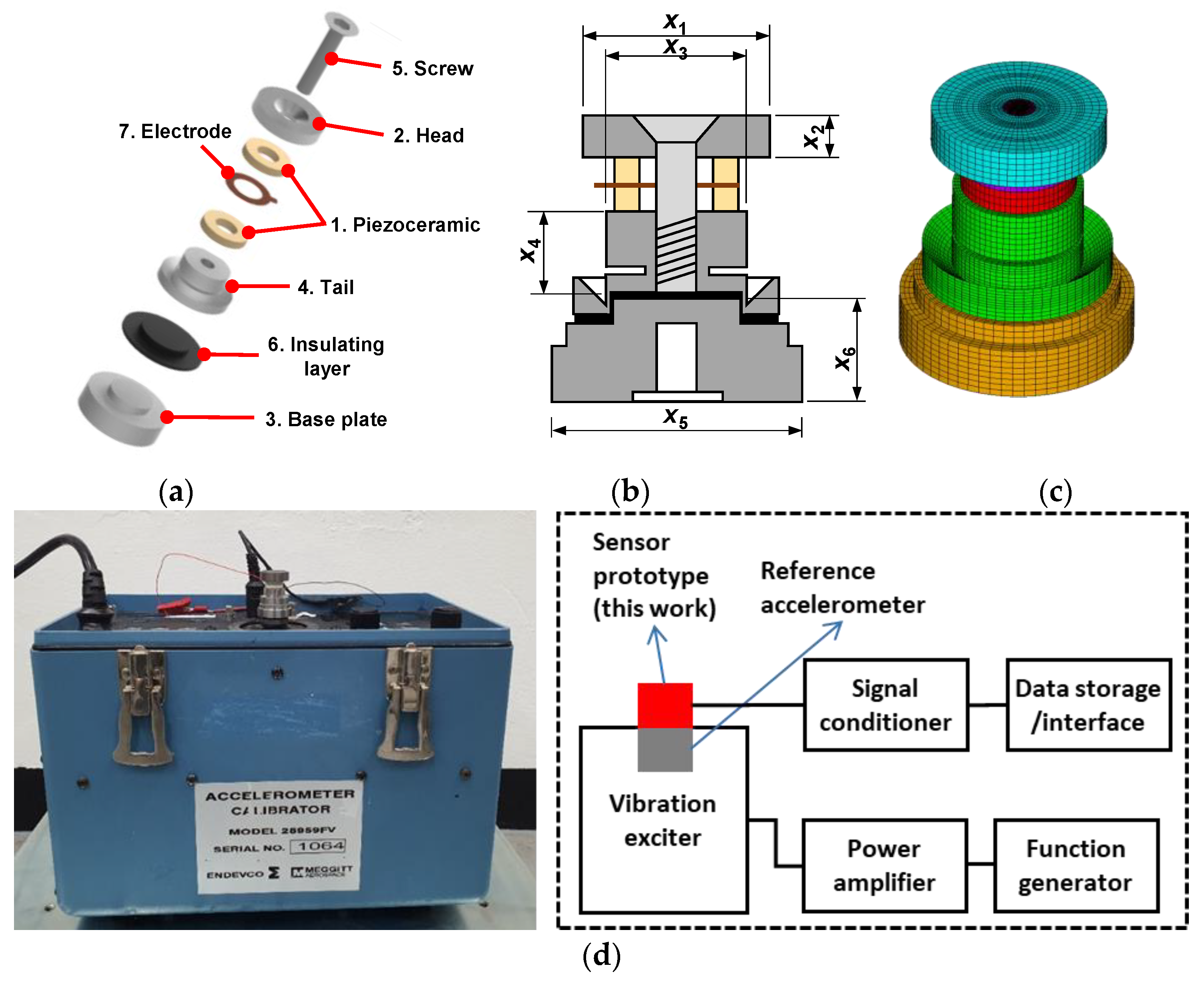
Figure 1a is an exploded diagram showing the structure and arrangement of a typical compression-mode piezoelectric accelerometer sensor with a central preload. The piezoelectric element (1) consists of two piezoceramic rings cut for the longitudinal effect and oriented with their polarities opposite from the central electrode. The two piezoceramic rings are connected electrically in parallel and mechanically in series. They are preloaded under a compressive force between the head (seismic mass) (2) and base plate (3) through the tail (4) by a screw (5). The insulating layer (6) was inserted into the gap between the tail and the base plates. The electrode (7) captures the output signal and feeds it to the connector. When the base plate is accelerated, the seismic mass exerts a proportional force on the piezoceramic element.
Compression-mode accelerometer designs were obtained by numerically optimizing the component design variables related to the head, tail and base plate (Figure 1b). The design and dimensions related to the piezoceramic element were fixed and the same as those of the sintered sample above. Optimization to improve charge sensitivity and resonant frequency characteristics was performed using finite element analysis (FEA) via piezoelectric analysis and metamodeling for free and fixed boundary conditions (Figure 1c). The methodology is described in Supplementary Materials. The required material constants of the constituent components, including those of the KNN-based piezoceramic [35], are presented in Tables S1 and S2.
The accelerometer sensor prototypes were fabricated by assembling the internal sensor components and piezoceramic rings prepared according to the numerically optimized designs (Figure S2). The components such as head, tail and base were manufactured using a CNC (computer numerically controlled) milling machine tool. The specially designed zigs were used for accurate and reliable assembly of the constituent components. The gap between the tail and base was filled with epoxy (ECCOBOND A 359 LV; Emerson & Curming, Germantown, WI, USA) for insulation. In tightening with a screw, the torque value was optimized using a digital torque wrench. The charge sensitivity was evaluated using a portable accelerometer calibrator (28959FV; Endevco, San Juan Capistrano, CA, USA) that includes a built-in vibration exciter, signal generator and computer-controlled amplifier/servo mechanism. The applied acceleration range was between 0.1–10 g (g, gravitational acceleration = 9.8 m/s2). The frequency response property of the assembled sensor prototypes was characterized using an impedance analyzer (SI 1260; Solartron Analytical, Farnborough, Hampshire, UK) and a vibration exciter (SE-9; SPEKTRA, Dresden, Germany). The experimental setup for the vibration test is presented in Figure 1d. The sensing performance data of a PZT-based accelerometer were also used for comparison [36].
3. Results
3.1. Properties of Lead-Free KNN-BNKLZ-BS Ceramic Rings
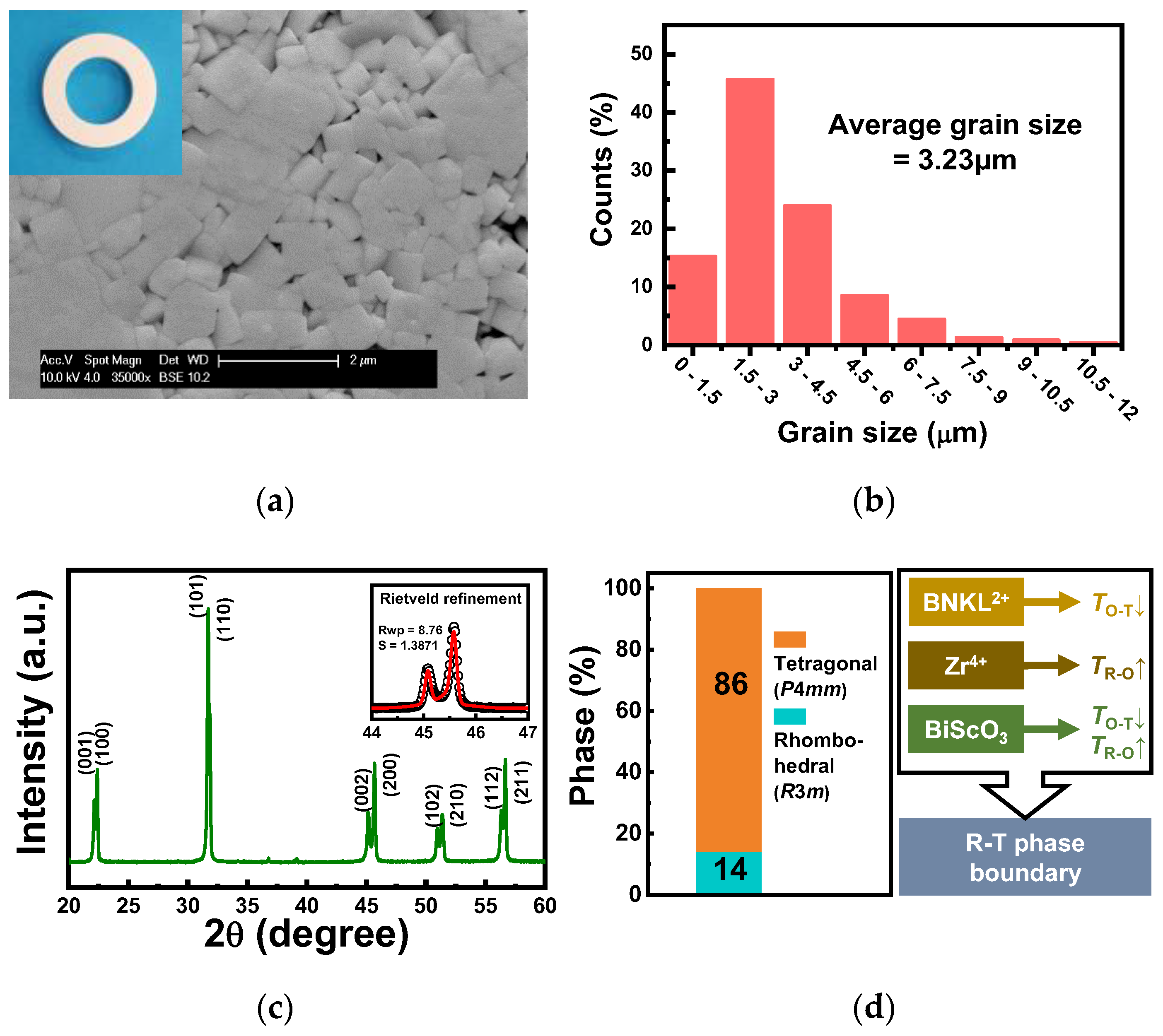
According to SEM images, the KNN-BNKLZ-BS ceramic rings had well-developed perovskite cube grains with clear edges, which is a typical microstructure of KNN systems as a result of sufficient sintering reaction (Figure 2a). The average grain size was estimated to be about 3.23 μm (Figure 2b). The room-temperature XRD pattern revealed that the ceramic rings had a pure perovskite structure without any secondary phases (Figure 2c), confirming a perovskite solid solution induced by the complete diffusion of BNKLZ and BS dopants into the KNN lattice. Based on a Rietveld refinement of the θ-2θ XRD pattern (Figure S3), the resulting ceramic rings revealed a two-phase coexistence comprising R (R3 m) and T (P4 mm) phases with their respective phase fraction of 14% and 86% (Figure 2d), eventually leading to a T-rich R–T phase boundary structure. It is also known that this R–T phase fraction is adjacent to a condition that causes the maximum piezoelectric response in KNN systems [34,37]. There has been recent progress in the development of KNN systems [10,11,12,13,14]. The construction of an R–T phase boundary at/near room temperature was a major breakthrough in the piezoelectric activity of polycrystalline KNN ceramics, such as the classic morphotropic phase boundary (MPB) in the PZT system. Consequently, co-doping with 3 mol% BNKLZ and 1 mol% BS effectively modified the room-temperature phase structure of orthorhombic (O) KNN by shifting two intrinsic phase transition temperatures, i.e., the R–O transition at −123 °C (TR-O) and the O–T transition at 210 °C (TO-T), toward the room temperature region. As also illustrated in Figure 2d, dopants with (Bi,M)2+ (M: alkali metals) and Zr4+ ions are known to play effective roles in decreasing TO-T and increasing TR-O, respectively [38,39]. BS is also known to be effective in decreasing TO-T and increasing TR-O [40,41]. All the changes in phase transitions including TC are related to the distortion of the crystal lattice induced by (Bi,M)2+ substitution for the A-site and Zr4+ for the B-site in KNN [39].
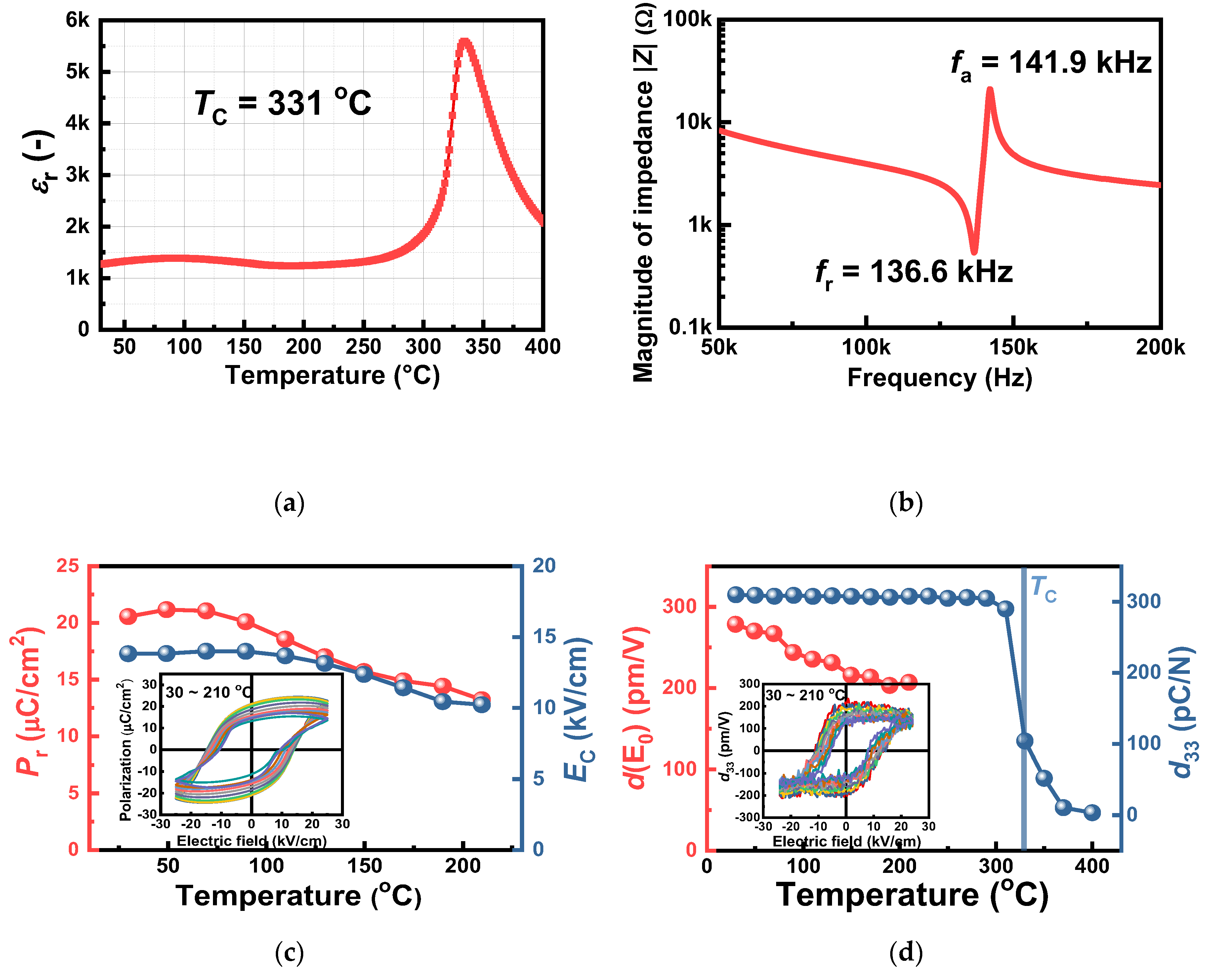
The room-temperature values of static d33 and large-signal d33* (= Smax/Emax) of the KNN-BNKLZ-BS ceramic ring were measured to be about 310 pC/N and 441 pm/V. The Curie temperature (Tc) determined from the dielectric peak position was 331 °C (Figure 3a). These piezoelectric properties are directly related to the sensitivity and usage temperature for piezoelectric sensing, suggesting that the present KNN composition is practically feasible. The impedance–frequency profile revealed that the anti-resonant (fa) and resonant frequencies (fr) were 141.9 and 136.6 kHz, respectively, (Figure 3b) and the electromechanical coupling factor kp was determined to be 0.30. Other physical properties are presented in Table 1, including those of the PZT ceramic rings prepared for comparison.
To gain insights into the temperature behavior of the ferroelectric/piezoelectric responses of the KNN-BNKLZ-BS ceramic rings, the P-E hysteresis loops and field-dependent, small-signal d33 loops were obtained between 30–210 °C (see the insets of Figure 3c,d). Since the temperature-dependent, small-signal d33 is considered to be equivalent to the value measured by a quasi-static d33 meter [42,43], the field-dependent d33 was measured to investigate the in-situ temperature behavior of piezoelectric activity. Finally, the temperature dependence of remanent polarization Pr, coercive field Ec and small-signal d(E0) was obtained from the hysteresis loops, as shown in Figure 3c,d. Here, the d(E0) was determined to be a positive value in a zero field in the small-signal d33(E) loops at various temperatures (see the inset). All of the in-situ values for Pr, Ec and d(E0) decreased gradually with increasing temperature from 30 to 210 °C. At 110 °C, a 9.9% decrease in Pr as well as a 15.4% decrease in d(E0) were observed with respect to their room-temperature values (Pr~20.6 μC/cm2, d(E0)~278.6 pm/V), showing relatively stable temperature behavior. The thermal aging experiments showed that the static d33 remained unchanged up to about 300 °C, showing excellent thermal stability (with only a 1.9% drop in its room-temperature value), followed by a drastic decrease with a further increase in temperature, owing to the presence of Tc at around 330 °C. The resulting piezoelectric properties of the present KNN composition showed sufficient potential for use in piezoelectric sensors.
3.2. Numerical Simulations of the KNN-Based Piezoelectric Accelerometer Design
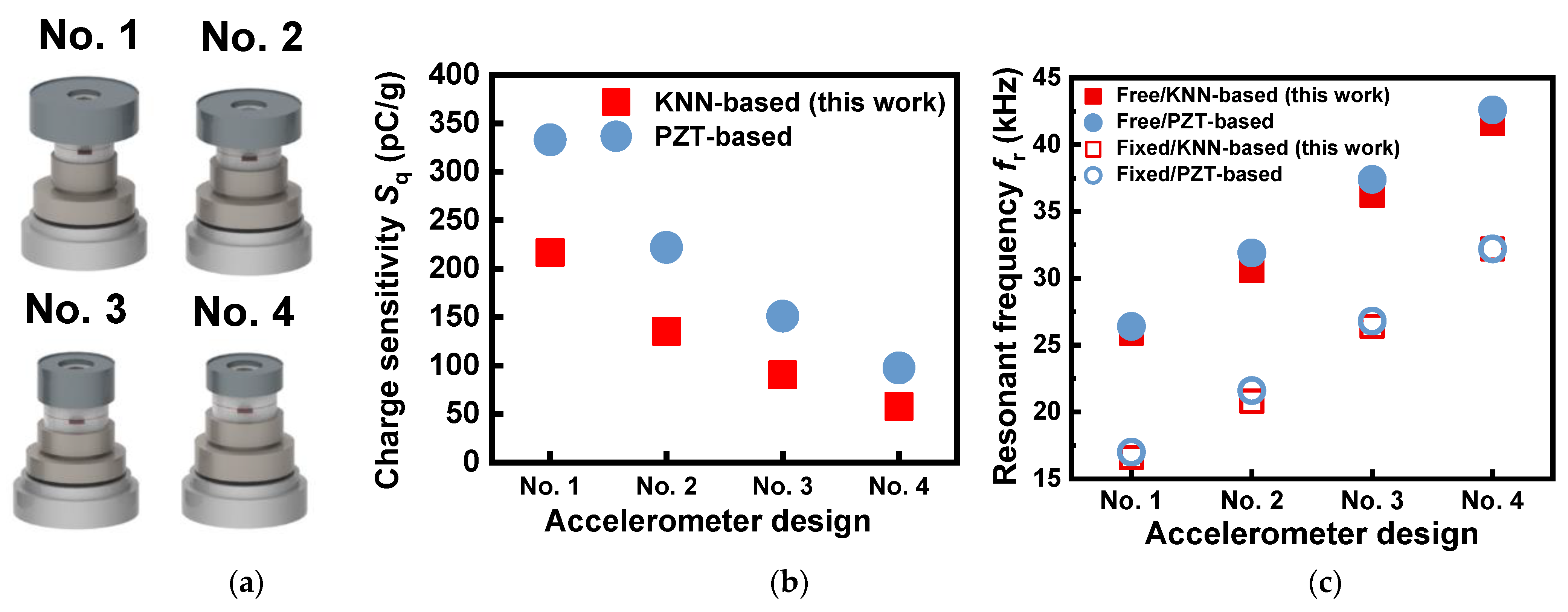
Figure 4a shows the three-dimensional images of four accelerometer designs obtained by numerical simulations. The designs numbered 1 to 4 were characterized using different dimensions of the constituent components (Table 2). By using the material data of the KNN-based ceramics [35], we could obtain numerically analyzed results for charge sensitivity Sq and resonant frequency fr for the optimized designs, as shown in Figure 4b,c. It can be seen that the Sq value, which is related to the sensitivity of the accelerometer, decreased from 216.8 pC/g to 57.9 pC/g, when the design changed from No. 1 to No. 4. The most influential factors among the investigated design variables were the head’s O.D. (x1) and height (x2). The observed variation was thus found to be associated with the weight of the head, which is proportional to the Sq property.
For the four optimized designs, the impedance–frequency characteristics obtained from the numerical simulations of the free and fixed boundary conditions are presented in Figure S4. The fr values for the fixed mode were lower by about 9.3–9.8 kHz compared to those for the free mode. Unlike the trend in Sq, the fr value for both the free and fixed modes increased almost linearly, as the design changed from No. 1 to No. 4. The fr value for the fixed mode, which corresponds to a mounted or attached condition in a practical sensor system, increased from 16.6 to 32.2 kHz, and these levels of fr were found to be in the range of those of commercial piezoelectric accelerometers. From Figure 4b,c, the correlation between Sq and fr was found to be negative, that is, a higher Sq resulted in a lower fr. Hence, the two performance indicators have a trade-off relation.
When compared with the numerically analyzed results of the PZT-based accelerometer, the present Sq values of the KNN-based prototype were lower, mostly resulting from the effect of reduced piezoelectric activity; the d33 values used in the numerical work were 321 pC/N for KNN and 400 pC/N for PZT. However, the fr values obtained from the KNN-based accelerometer prototype were almost equivalent to those of the PZT-based one. This indicates that the fr property is not affected by the piezoelectric activity of the piezo element but by structural design factors (dimensions and configuration) or the mechanical properties of the components.
3.3. Characterization of Accelerometer Prototype Built Using Lead-Free KNN-BNKLZ-BS Ceramics
Using the designs obtained from the numerical work, four kinds of accelerometer prototypes were fabricated using KNN-BNKLZ-BS ceramics (Figure 5a), and their charge-to-acceleration characteristics were measured by a portable accelerometer calibrator, as shown in Figure 5b. In the investigated acceleration ranges, the values of Pearson’s correlation coefficient r were almost unity for all of the sensor prototypes, revealing a perfect linear response between the charge and acceleration. These outstanding results prove the high reliability of the assembled sensor prototypes. The slopes, representing a charge sensitivity Sq, were determined from their linear relation (Figure 5c and Table 3). The measured Sq decreased from 223.8 to 55.1 pC/g, as the accelerometer design changed from No. 1 to No. 4. By considering the piezoceramic and seismic mass (head), the Sq was simplified and is given by Equation (1) [44].
Sq = n⋅d33⋅ms⋅g
Here, n, ms and g are the number of piezoceramic layers, the weight of seismic mass and acceleration, respectively. According to the numerically analyzed Sq property, the design factor most affecting sensitivity was the head. In a real system, likewise, the weight of the head positively affected charge sensitivity with strong correlation (Figure 5c).
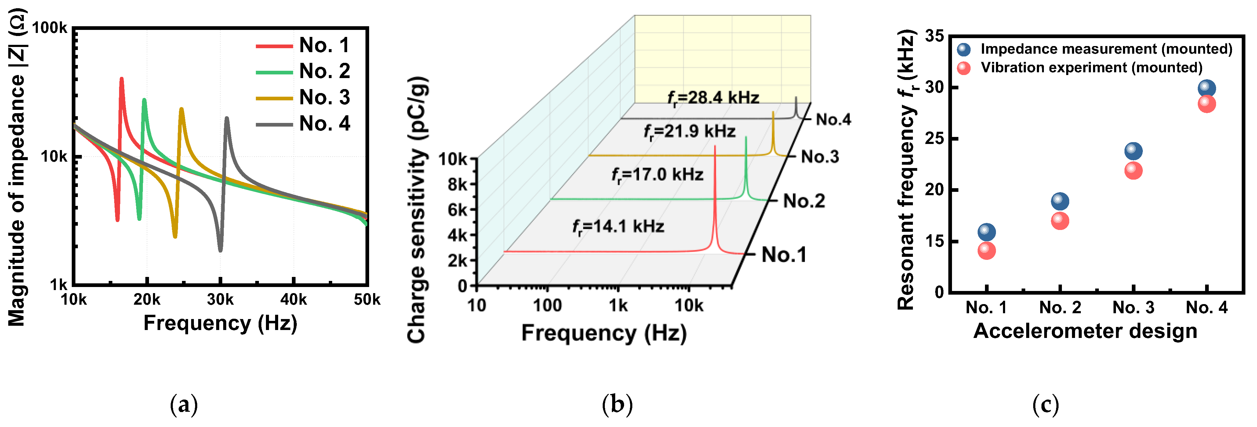
Next, impedance tests and vibration experiments were performed to investigate the frequency response and fr properties. Figure 6a,b show the impedance–frequency spectra measured in the free and fixed condition and the frequency response profiles obtained from the vibration experiments in the fixed condition, respectively, for four different accelerometer prototypes made of KNN-BNKLZ-BS ceramic rings. The properties of anti-resonant frequency fa, including impedance Z, are also presented in Figure S5. In the impedance measurement, the fr was found to vary from 15.9 to 29.9 kHz, depending on the design. The measured fr values were found to be almost similar to those obtained from the vibration experiment, with only a slight difference (1.5 to 1.9 kHz). The resonant frequency fr of the piezoelectric accelerometer was simplified and is given by Equation (2) [45].
Here, Dp, tp, k and E33 are the diameter, thickness, stiffness and Young’s modulus of the piezoceramic, respectively. From this relation, it is known that the weight of the head (ms) negatively affects the resonant frequency fr; . Therefore, the lower ms leads to an increase in fr, as the design changes from No. 1 to No. 4, consistent with the above numerical results. This negative correlation of fr with ms demonstrates there is an inverse relationship between the two key sensing performance metrics of sensitivity and resonant frequency. Since the design variables can only improve one of the two performance metrics while sacrificing the other, a design can be chosen to enhance either the sensitivity or the resonant frequency for vibration sensing. We also note that the experimentally measured fr values were lower than the numerically calculated values (Figure 4c): in the fixed condition, their differences were 2.5 to 4.5 kHz. These discrepancies between experimental results and numerical predictions might be related to loose boundaries or interfaces inside the real system, while the numerical analysis assumed perfect contacts between the internal components. It is also believed that this is related to the difficulties in uniformly controlling the epoxy layer thickness relative to the fr.
From a practical standpoint, it is extremely important that the piezoelectric accelerometer has a large flat frequency range, as this extends its usable detection range below a critical point of fr [1,46]. The flatness was determined from the frequency response profiles obtained from the vibration experiments, as presented in Table 4. The amplitude deviations were employed as the performance criteria, based on the requirements used in commercial sensors, which were ±5%, ±10% and ±3 dB in the amplitude-frequency curves [46,47]. The flat response range, determined from Figure 6b, became broader as the mounted fr increased. The observed fr-dependent flat frequency ranges were substantially high compared to those of commercial PZT accelerometers [47], proving the reliability of the modified KNN-based accelerometer prototypes.
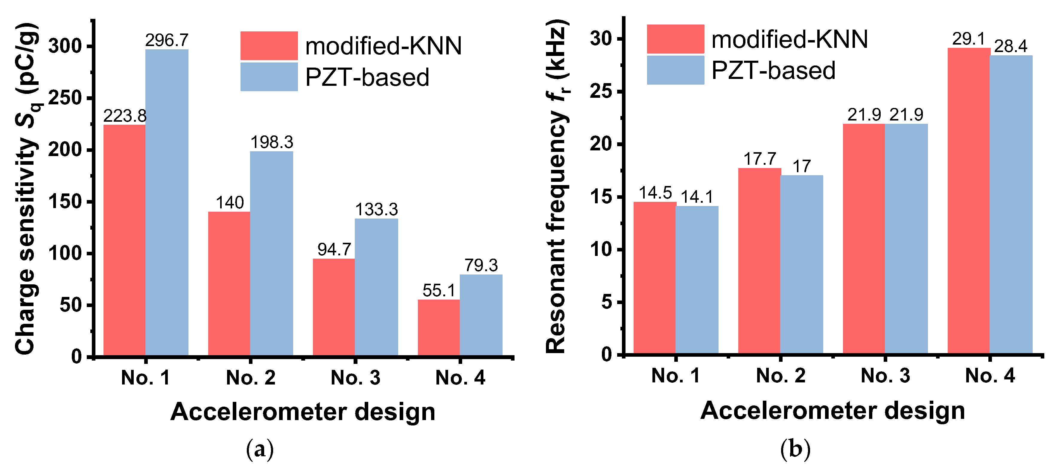
Figure 7 shows the comparison of Sq and fr for the accelerometer prototypes made of the modified-KNN and PZT ceramics. The Sq values obtained from the KNN-based accelerometers were 24.6 to 30.5% lower than those of the PZT-based accelerometers, similar to the numerically analyzed results above (Figure 4b). This primarily results from the effect of d33 (310 pC/N), which is lower than that of PZT (400 pC/N), considering the relation in Equation (1). In contrast, the fr properties of the KNN-based accelerometers were at nearly the same level as those of the PZT-based accelerometer. When compared to BNT-based accelerometers [32,33], the sensing performance of the present KNN-based accelerometer was excellent. For example, the charge sensitivity value of the BNT-based sensor was as low as 29.1 or 42.6 pC/g at frequencies ranging from 50 Hz to 8.24 kHz, while the KNN-based accelerometer showed a much greater sensitivity of 223.8 pC/g within a similar frequency range (10 Hz to 8.0 kHz). Consistent with the numerical results in Figure 4c, the experimentally measured data also revealed that fr is a function of the mechanical properties of the materials and the design parameters (Equation (2)), not piezoelectric activity.
4. Conclusions
The design, fabrication and sensing characteristics of a piezoelectric accelerometer built using lead-free, KNN-based ceramics were comprehensively investigated. Polycrystalline KNN-based ceramic rings, specially modified by doping with BNKLZ and BS, were prepared for integration into a compression-mode accelerometer. The sintered ceramic rings showed a T-rich R–T phase boundary structure (a mixture of 86% T phase and 14% R phase) with a large d33 of 310 pC/N and a high Tc of 331 °C. Four compression-mode accelerometer designs and their resulting Sq and fr properties were obtained by numerically optimizing the structural designs of the sensor components, including head (seismic mass), tail and base plate. Finally, the accelerometer sensor prototypes were fabricated using the proposed designs and KNN-BNKLZ-BS ceramic rings. They exhibited excellent sensing performance with high levels of Sq (55.1 to 223.8 pC/g) and mounted fr (14.1 to 28.4 kHz). Moreover, there was a perfect linearity between charge and acceleration, with a Pearson’s correlation coefficient r close to 1 for all of the assembled sensor prototypes. The experimentally measured flat frequency response ranges were significantly high and comparable to those of commercial PZT accelerometers. The trade-off relationship between the Sq and fr was also experimentally confirmed, consistent with the numerically analyzed results. In light of these desirable features, the present modified-KNN ceramic has practical potential for applications in lead-free piezoelectric sensors.
Supplementary Materials
The following supporting information can be downloaded at https://www.mdpi.com/article/10.3390/s23021029/s1: Table S1: Component materials and their mechanical properties (density, Young’s modulus and Poisson’s ratio); Table S2: Electrical and mechanical properties of KNN-based piezoceramic used for numerical simulation [34]; Figure S1: Preparation conditions of KNN-0.03BNKLZ-0.01BS ceramic rings by conventional solid-state powder method; The methodology of design optimization: the related references [48,49,50,51,52] are cited from the supplementary materials; Figure S2: Fabrication procedures of a compressive-type piezoelectric accelerometer prototype using KNN-BNKLZ-BS ceramic rings and sensor components: a specially designed zig was used for reliably aligning each sensor component, and an injection mold of our own design was also used to precisely control the amount of epoxy to be injected; Figure S3: Rietveld refinement of the XRD pattern of the KNN-003BNKLZ-0.01BS ceramic ring. Results of cell parameters, phase fraction and reliability factors (Rwp and S) are listed in the table; Figure S4: Impedance–frequency spectra and values of fr, fa and Z obtained from numerical simulation using free and fixed boundary conditions for KNN-based accelerometer designs (Nos. 1 to 4); Figure S5: Impedance–frequency profiles and values of resonant and anti-resonant frequencies (fr and fa) and magnitude of impedance ∣Z∣ experimentally measured under free and fixed conditions from impedance tests for KNN-based accelerometer prototypes (design Nos. 1 to 4).
Author Contributions
Conceptualization, validation, formal analysis, writing—original draft preparation, M.-K.L.; investigation, methodology, formal analysis, B.-H.K.; conceptualization, supervision, writing—review and editing, G.-J.L. All authors have read and agreed to the published version of the manuscript.
Funding
This research was supported by the Korean Nuclear R&D program organized by the National Research Foundation of Korea (NRF) grant (RS-2022-00144147) funded by the Korean government (Ministry of Science and ICT) and by the Korea Atomic Energy Research Institute (KAERI) R&D program.
Institutional Review Board Statement
Not applicable.
Informed Consent Statement
Not applicable.
Data Availability Statement
Not applicable.
Conflicts of Interest
The authors declare no conflict of interest.
References
- Gautschi, G. Piezoelectric Sensorics: Force, Strain, Pressure, Acceleration and Acoustic Emission Sensors, Materials and Amplifiers; Springer: Berlin, Germany, 2002. [Google Scholar]
- Restriction of the Use of Certain hazardous Substances in Electrical and Electronic Equipment (RoHS), EU-Directive 2002/95/EC. Off. J. Eur. Union 2003, 46, 19–23.
- Rödel, J.; Li, J.F. Lead-free piezoceramics: Status and perspectives. MRS Bull. 2018, 43, 576–580. [Google Scholar] [CrossRef] [Green Version]
- Zheng, T.; Wu, J.; Xiao, D.; Zhu, J. Recent development in lead-free perovskite piezoelectric bulk materials. Prog. Mater. Sci. 2018, 98, 552–624. [Google Scholar] [CrossRef]
- Wu, J. Advances in Lead-Free Piezoelectric Materials; Springer: Singapore, 2018. [Google Scholar]
- Aksel, E.; Jones, J.L. Advances in lead-free piezoelectric materials for sensors and actuators. Sensors 2010, 10, 1935–1954. [Google Scholar] [CrossRef]
- Wu, J.; Xiao, D.; Zhu, J. Potassium-sodium niobate lead-free piezoelectric materials: Past, present, and future of phase boundaries. Chem. Rev. 2015, 115, 2559–2595. [Google Scholar] [CrossRef]
- Wu, J.; Xiao, D.; Zhu, J. Potassium-sodium niobate lead-free piezoelectric ceramics: Recent advances and perspectives. J. Mater. Sci. Mater. Electron. 2015, 26, 9297–9308. [Google Scholar] [CrossRef]
- Saito, Y.; Takao, H.; Tani, T.; Nonoyama, T.; Takatori, K.; Homma, T.; Nagaya, T.; Nakamura, M. Lead-free piezoelectrics. Nature 2004, 432, 84–87. [Google Scholar] [CrossRef]
- Xu, K.; Li, J.; Lv, X.; Wu, J.; Zhang, X.; Xiao, D.; Zhu, J. Superior piezoelectric properties in potassium-sodium niobate lead-free ceramics. Adv. Mater. 2016, 28, 8519–8523. [Google Scholar] [CrossRef]
- Wang, X.; Wu, J.; Xiao, D.; Zhu, J.; Cheng, X.; Zheng, T.; Zhang, B.; Lou, X.; Wang, X. Giant piezoelectricity in potassium-sodium niobate lead-free ceramics. J. Am. Chem. Soc. 2014, 136, 2905–2910. [Google Scholar] [CrossRef]
- Wu, B.; Wu, H.; Wu, J.; Xiao, D.; Zhu, J.; Pennycook, S.J. Giant piezoelectricity and high Curie temperature in nanostructured alkali niobate lead-free piezoceramics through phase coexistence. J. Am. Chem. Soc. 2016, 138, 15459–15464. [Google Scholar] [CrossRef]
- Wang, X.; Zheng, T.; Wu, J.; Xiao, D.; Zhu, J.; Wang, H.; Wang, X.; Lou, X.; Gu, Y. Characteristics of giant piezoelectricity around the rhombohedral-tetragonal phase boundary in (K,Na)NbO3-based ceramics with different additives. J. Mater. Chem. A 2015, 3, 15951–15961. [Google Scholar] [CrossRef]
- Wang, X.; Wu, J.; Xiao, D.; Cheng, X.; Zheng, T.; Zhang, B.; Lou, X.; Zhu, J. Large d33 in (K,Na)(Nb,Ta,Sb)O3-(Bi,Na,K)ZrO3 lead-free ceramics. J. Mater. Chem. A 2014, 2, 4122–4126. [Google Scholar] [CrossRef]
- Oh, Y.; Noh, J.; Yoo, J.; Kang, J.; Hwang, L.; Hong, J. Dielectric and piezoelectric properties of CeO2-added nonstoichiometric (Na0.5K0.5)0.97(Nb0.96Sb0.04)O3 ceramics for piezoelectric energy harvesting device applications. IEEE Trans. Ultrason. Ferroelectr. Freq. Control 2011, 58, 1860–1866. [Google Scholar] [CrossRef]
- Kim, S.H.; Leung, A.; Koo, C.Y.; Kuhn, L.; Jiang, W.; Kim, D.J.; Kingon, A.I. Lead-free (Na0.5K0.5)(Nb0.95Ta0.05)O3-BiFeO3 thin films for MEMS piezoelectric vibration energy harvesting devices. Mater. Lett. 2012, 69, 24–26. [Google Scholar] [CrossRef]
- Jeong, C.K.; Park, K.I.; Ryu, J.; Hwang, G.T.; Lee, K.J. Large-area and flexible lead-free nanocomposite generator using alkaline niobate particles and metal nanorod filler. Adv. Funct. Mater. 2014, 24, 2620–2629. [Google Scholar] [CrossRef]
- Seo, I.T.; Choi, C.H.; Song, D.; Jang, M.S.; Kim, B.Y.; Nahm, S.; Kim, Y.S.; Sung, T.H.; Song, H.C. Piezoelectric properties of lead-free piezoelectric ceramics and their energy harvester characteristics. J. Am. Ceram. Soc. 2013, 96, 1024–1028. [Google Scholar] [CrossRef]
- Wang, X.X.; Or, S.W.; Lam, K.H.; Chan, H.L.W.; Choy, P.K.; Liu, P.C.K. Cymbal actuator fabricated using (Na0.46K0.46Li0.08)NbO3 lead-free piezoceramic. J. Electroceram. 2006, 16, 385–388. [Google Scholar] [CrossRef]
- Kim, M.S.; Jeon, S.; Lee, D.S.; Jeong, S.J.; Song, J.S. Lead-free NKN-5LT piezoelectric materials for multilayer ceramic actuator. J. Electroceram. 2009, 23, 372–375. [Google Scholar] [CrossRef]
- Lee, K.S.; Yoo, J.; Hwang, L. Electrical properties of (Na,K,Li)(Nb,Sb,Ta)O3 ceramics for multilayer-type piezoelectric actuator. Ferroelectrics 2017, 515, 18–24. [Google Scholar] [CrossRef]
- Gao, L.; Ko, S.W.; Guo, H.; Hennig, E.; Randall, C.A. Demonstration of copper co-fired (Na,K)NbO3 multilayer structures for piezoelectric applications. J. Am. Ceram. Soc. 2016, 99, 2017–2023. [Google Scholar] [CrossRef]
- Hagh, N.M.; Jadidian, B.; Ashbahian, E.; Safari, A. Lead-free piezoelectric ceramic transducer in the donor-doped K1/2Na1/2NbO3 solid solution system. IEEE Trans. Ultrason. Ferroelectr. Freq. Control 2008, 55, 214–224. [Google Scholar] [CrossRef] [PubMed]
- Shen, Z.Y.; Li, J.F.; Chen, R.M.; Zhou, Q.F.; Shung, K.K. Microscale 1-3-type (Na,K)NbO3-based Pb-free piezocomposites for high-frequency ultrasonic transducer applications. J. Am. Ceram. Soc. 2011, 94, 1346–1349. [Google Scholar] [CrossRef] [PubMed]
- Ma, J.P.; Xue, S.D.; Zhao, X.Y.; Wang, F.F.; Tang, Y.X.; Duan, Z.H.; Wang, T.; Shi, W.Z.; Yue, Q.W.; Zhou, H.F.; et al. High frequency transducer for vessel imaging based on lead-free Mn-doped (K0.44Na0.56)NbO3 single crystal. Appl. Phys. Lett. 2017, 111, 092903. [Google Scholar] [CrossRef]
- Yang, J.O.; Zhu, B.P.; Zhang, Y.; Chen, S.; Yang, X.F.; Wei, W. New KNN-based lead-free piezoelectric ceramic for high-frequency ultrasound transducer applications. Appl. Phys. A 2015, 118, 1177–1181. [Google Scholar]
- Lam, K.H.; Lin, D.M.; Chan, H.L.W. Lead-free acoustic emission sensors. Rev. Sci. Instrum. 2007, 78, 115109. [Google Scholar] [CrossRef] [Green Version]
- Jeong, Y.; Byeon, S.; Park, M.; Yoo, J. Sensitivity properties of acoustic emission sensor using lead-free (Na,K,Li)(Nb,Ta,Zn)O3 system ceramics. Integr. Ferroelectr. 2012, 140, 123–131. [Google Scholar] [CrossRef]
- Hong, J.; Yoo, J.; Lee, K.; Lee, S.; Song, H. Characteristics of acoustic emission sensor using lead-free (Li,Na,K)(Na,Ta,Sb)O3 ceramics for fluid leak detection at power plant valves. Jpn. J. Appl. Phys. 2008, 47, 2192–2194. [Google Scholar] [CrossRef]
- Duan, W.H.; Wang, Q.; Quek, S.T. Applications of piezoelectric materials in structural health monitoring and repair. Materials 2010, 3, 5169–5194. [Google Scholar] [CrossRef] [Green Version]
- Baptista, F.G.; Filho, J.V. A new impedance measurement system for PZT-based structural health monitoring. IEEE Trans. Instrum. Meas. 2009, 58, 3603–3608. [Google Scholar] [CrossRef]
- Choy, S.H.; Wang, X.X.; Chan, H.L.W.; Choy, C.L. Study of compressive type accelerometer based on lead-free BNKBT piezoceramics. Appl. Phys. A 2006, 82, 715–718. [Google Scholar] [CrossRef]
- Choy, S.H.; Wang, X.X.; Chan, H.L.W.; Choy, C.L. Electromechanical and ferroelectric properties of (Bi1/2Na1/2)TiO3-(Bi1/2K1/2)TiO3-(Bi1/2Li1/2)TiO3-BaTiO3 lead-free piezoelectric ceramics for accelerometer application. Appl. Phys. A 2007, 89, 775–781. [Google Scholar] [CrossRef]
- Lee, M.K.; Yang, S.A.; Park, J.J.; Lee, G.J. Proposal of a rhombohedral-tetragonal phase composition for maximizing piezoelectricity of (K,Na)NbO3 ceramics. Sci. Rep. 2019, 9, 4195. [Google Scholar] [CrossRef] [PubMed]
- Shi, H.; Chen, J.; Wang, R.; Dong, S. Full set of material constants of (Na0.5K0.5)NbO3-BaZrO3-(Bi0.5Li0.5)TiO3 lead-free piezoelectric ceramics at the morphotropic phase boundary. J. Alloys Compd. 2016, 655, 290–295. [Google Scholar] [CrossRef]
- Lee, M.K.; Han, S.H.; Park, J.J.; Lee, G.J. A theoretical and empirical investigation of design characteristics in a Pb(Zr,Ti)O3-based piezoelectric accelerometer. Sensors 2020, 20, 3545. [Google Scholar] [CrossRef]
- Lee, M.K.; Bu, S.D.; Lee, G.J. Co-doping effect of BiGaO3 and (Bi,Na,K,Li)ZrO3 on multi-phase structure and piezoelectric properties of (K,Na)NbO3 lead-free ceramics. Energies 2019, 12, 886. [Google Scholar] [CrossRef] [Green Version]
- Cheng, X.; Wu, J.; Wang, X.; Zhang, B.; Zhu, J.; Xiao, D.; Wang, X.; Lou, X. Giant d33 in (K,Na)(Nb,Sb)O3-(Bi,Na,K,Li)ZrO3 based lead free piezoelectrics with high Tc. Appl. Phys. Lett. 2013, 103, 052906. [Google Scholar] [CrossRef]
- Cheng, X.; Gou, Q.; Wu, J.; Wang, X.; Zhang, B.; Xiao, D.; Zhu, J.; Wang, X.; Lou, X. Dielectric, ferroelectric, and piezoelectric properties in potassium sodium niobate ceramics with rhombohedral-orthorhombic and orthorhombic-tetragonal phase boundaries. Ceram. Int. 2014, 40, 5771–5779. [Google Scholar] [CrossRef]
- Cheng, X.; Wu, J.; Wang, X.; Zhang, B.; Lou, X.; Wang, X.; Xiao, D.; Zhu, J. Mediating the contradiction of d33 and Tc in potassium-sodium niobate lead-free piezoceramics. ACS Appl. Mater. Interfaces 2013, 5, 10409–10417. [Google Scholar] [CrossRef]
- Yang, Y.; Dai, Q.; Chen, T.; Liu, Y.; Zhang, T.; Zhang, J. Role of BiScO3 in phase structure and electrical properties of potassium sodium niobate ternary materials. J. Alloys Compd. 2019, 770, 466–472. [Google Scholar] [CrossRef]
- Wang, K.; Yao, F.Z.; Jo, W.; Gobeljic, D.; Shvartsman, V.V.; Lupascu, D.C.; Li, J.F.; Rӧdel, J. Temperature-insensitive (K,Na)NbO3-based lead-free piezoactuator ceramics. Adv. Funct. Mater. 2013, 23, 4079–4089. [Google Scholar] [CrossRef]
- Zhou, J.S.; Wang, K.; Yao, F.Z.; Zheng, T.; Wu, J.; Xiao, D.; Zhu, J.; Li, J.F. Multi-scale thermal stability of niobate-based lead-free piezoceramics with large piezoelectricity. J. Mater. Chem. C 2015, 3, 8780–8787. [Google Scholar] [CrossRef]
- Kwon, J.R. Influence of effective piezoelectric properties on performance of piezoelectric accelerometer for vibration measurements. J. Korean Ceram. Soc. 1995, 32, 945–949. [Google Scholar]
- Koo, G.H. Design, Fabrication, and Calibration of Piezoelectric Accelerometer. Master’s Thesis, Korea Advanced Institute of Science and Technology, Daejeon, Korea, 1989. [Google Scholar]
- Serridge, M.; Licht, T.R. Piezoelectric Accelerometer and Vibration Preamplifiers. In Theory and Application Handbook; Brüel & Kjær: Nærum, Denmark, 1987. [Google Scholar]
- Available online: http://www.skf.com/group/products/condition-monitoring-systems/sensors/vibration-sensors (accessed on 1 August 2022).
- Ross, P. Taguchi Techniques for Quality Engineering; McGraw-Hill: New York, NY, USA, 1996. [Google Scholar]
- Montgomery, D.C. Design Analyses of Experiments, 3rd ed.; John Wiley & Sons: New York, NY, USA, 1997. [Google Scholar]
- Kumar, V. Optimization and modelling of process parameters involved in ultrasonic machining of glass using design of experiments and regression approach. Am. J. Mater. Eng. Technol. 2013, 1, 13–18. [Google Scholar]
- Kumar, J.P.N.; Kumar, S.J.; Jeyathilak, R.K.S.; Venkatesh, M.; Christopher, A.S.; Ganesh, K.C. Effect of design parameters on the static mechanical behavior of metal bellows using design of experiment and finite element analysis. Int. J. Interact. Des. Manuf. 2017, 11, 535–545. [Google Scholar] [CrossRef]
- Huang, D.; Allen, T.T.; Notz, W.I.; Zeng, N. Global optimization of stochastic black-box systems via sequential Kriging meta-models. J. Glob. Optim. 2006, 34, 441–466. [Google Scholar] [CrossRef]
Figure 1.
(a) Exploded diagram showing the constituent components of the compression-type piezoelectric accelerometer (1: piezoceramic ring; 2: head or seismic mass; 3: base plate; 4: tail; 5: screw; 6: insulating layer; 7: electrode). (b) Design variables used for finite element modeling (x1: head outer diameter, x2: head height, x3: tail outer diameter (O.D.), x4: tail height, x5: base outer diameter (O.D.), x6: base height). (c) Finite element model of a compression-mode accelerometer (total number of elements: 124,800, number of nodes: 134,977). (d) A photo showing experimental setup of the vibration test and its block diagram.

Figure 2.
(a) Thermally etched SEM image showing the typical microstructure of a sintered KNN-BNKLZ-BS ceramic ring (the inset is a photo of a ceramic ring ready to be assembled into a sensor prototype). (b) Grain size distribution. (c) Normal θ–2θ XRD pattern (inset is a Rietveld refinement pattern; the low-reliability factor value Rwp (= 8.76%) as well as the goodness-of-fit indicator S (= 1.3871) close to 1 suggest the reliability of the refinement). (d) Quantitative phase fraction obtained by Rietveld refinement.

Figure 3.
(a) Temperature-dependent dielectric constant εr of the KNN-BNKLZ-BS ceramic ring. (b) Impedance–frequency profile showing resonant frequency fr and anti-resonant frequency fa. (c) Temperature-dependent Pr and EC (inset shows temperature-dependent P-E loops between 30 and 210 °C). (d) In-situ temperature-dependent d(E0) and thermal aging of static d33 (inset shows temperature-dependent small-signal d33-E loops between 30 and 210 °C).

Figure 4.
(a) Three-dimensional images of the four accelerometer designs (Nos. 1 to 4). (b) Numerically calculated results of charge sensitivity Sq for the four designs built with KNN-BNKLZ-BS piezoelectric elements. (c) Numerically calculated results of resonant frequency fr of the four designs under free and fixed modes. Numerically analyzed results for PZT-based accelerometers [36] are also compared in (b,c).

Figure 5.
(a) Photos of accelerometer prototypes fabricated using the optimized designs (Nos. 1 to 4). (b) Charge versus acceleration measured for the corresponding accelerometer prototypes (test frequency = 159 Hz). (c) Comparison of the numerically analyzed charge sensitivity Sq and an experimentally measured value.

Figure 6.
(a) Impedance–frequency spectra measured from impedance measurements for accelerometer prototypes in the mounted condition. (b) Frequency response profiles measured from vibration experiments in the mounted condition. (c) Results of resonant frequency fr determined from both measurements.
Figure 6.
(a) Impedance–frequency spectra measured from impedance measurements for accelerometer prototypes in the mounted condition. (b) Frequency response profiles measured from vibration experiments in the mounted condition. (c) Results of resonant frequency fr determined from both measurements.

Figure 7.
Comparison of (a) charge sensitivity Sq and (b) resonant frequency fr of accelerometer prototypes made of KNN-BNKLZ-BS and PZT ceramics. Experimentally measured results for the PZT-based accelerometers were taken from ref. [36].
Figure 7.
Comparison of (a) charge sensitivity Sq and (b) resonant frequency fr of accelerometer prototypes made of KNN-BNKLZ-BS and PZT ceramics. Experimentally measured results for the PZT-based accelerometers were taken from ref. [36].


Table 1.
Material properties of KNN-BNKLZ-BS and PZT ceramic rings.
| Material Property | KNN-BNKLZ-BS | PZT (Ref. [36]) |
|---|---|---|
| Weight m (g) | 0.809 | 1.616 |
| Density ρ (kg/m3) | 4101.2 | 7767.7 |
| Outer diameter O.D. (mm) | 12.40 | 12.62 |
| Inner diameter I.D. (mm) | 7.46 | 7.52 |
| Thickness t (mm) | 2.56 | 2.57 |
| Remanent polarization Pr (μC/cm2) | 20.5 | 15.9 |
| Coercive field EC (kV/cm) | 13.8 | 14.7 |
| Dielectric constant εr | 1530 | 1850 |
| Loss factor tanδ | 0.03 | 0.02 |
| Electromechanical coupling factor kp | 0.30 | 0.36 |
| Mechanical quality factor Qm | 72 | 81 |
| Large-signal piezoelectric coefficient d33* (pm/V) | 441.1 | 726.2 |
| Static piezoelectric coefficient d33 (pC/N) | 310.0 ± 4.8 | 400.0 ± 2.1 |
| Curie temperature TC (°C) | 331 | 367 |
Table 2.
Values of optimized design variables (x1 to x6) for the four accelerometer designs and numerically analyzed charge sensitivity Sq and resonant frequency fr for the free and fixed boundary conditions.
Table 2.
Values of optimized design variables (x1 to x6) for the four accelerometer designs and numerically analyzed charge sensitivity Sq and resonant frequency fr for the free and fixed boundary conditions.
| Design no. | x1 (mm) | x2 (mm) | x3 (mm) | x4 (mm) | x5 (mm) | x6 (mm) | Free Mode | Fixed Mode | ||
|---|---|---|---|---|---|---|---|---|---|---|
| fr (kHz) | Sq (pC/g) | fr (kHz) | Sq (pC/g) | |||||||
| 1 | 23 | 7 | 13.94 | 5.68 | 26.4 | 2.35 | 25.9 | 216.8 | 16.6 | 216.8 |
| 2 | 20.5 | 5.75 | 15.1 | 4.91 | 24.4 | 3.2 | 30.6 | 135.3 | 20.8 | 135.3 |
| 3 | 15.08 | 7 | 15.1 | 4.53 | 24.4 | 1.63 | 36.2 | 90.5 | 26.4 | 90.5 |
| 4 | 15 | 4.28 | 15.2 | 4.78 | 24.4 | 3.03 | 41.6 | 57.9 | 32.2 | 57.9 |
Table 3.
Acceleration range, Pearson’s correlation coefficient, charge sensitivity and weight of head for the four accelerometer prototypes.
Table 3.
Acceleration range, Pearson’s correlation coefficient, charge sensitivity and weight of head for the four accelerometer prototypes.
| Design No. | Acceleration Range (g) | Pearson’s Correlation Coefficient r | Charge Sensitivity Sq (pC/g) | Weight of Head ms (gram) |
|---|---|---|---|---|
| 1 | 0.1–7 | 1 | 223.8 ± 0.1 | 51.8 |
| 2 | 0.1–10 | 1 | 140.0 ± 0.1 | 33.8 |
| 3 | 0.1–10 | 1 | 94.7 ± 0.03 | 21.6 |
| 4 | 0.1–10 | 0.9999 | 55.1 ± 0.04 | 12.9 |
Table 4.
Frequency response properties of the accelerometer prototypes obtained from vibration experiments.
Table 4.
Frequency response properties of the accelerometer prototypes obtained from vibration experiments.
| Design No. | Frequency Response | Mounted fr (kHz) | ||
|---|---|---|---|---|
| ±5% | ±10% | ±3 dB | ||
| 1 | 10 Hz to 4.2 kHz | 10 Hz to 5 kHz | 10 Hz to8.0 kHz | 14.1 |
| 2 | 10 Hz to 5.1 kHz | 10 Hz to 6.1 kHz | 10 Hz to 9.6 kHz | 17.0 |
| 3 | 10 Hz to 6.9 kHz | 10 Hz to 8.3 Hz | 10 Hz to 12.7 kHz | 21.9 |
| 4 | 10 Hz to 7.1 Hz | 10 Hz to 10.9 kHz | 10 Hz to 16.6 kHz | 28.4 |
Disclaimer/Publisher’s Note: The statements, opinions and data contained in all publications are solely those of the individual author(s) and contributor(s) and not of MDPI and/or the editor(s). MDPI and/or the editor(s) disclaim responsibility for any injury to people or property resulting from any ideas, methods, instructions or products referred to in the content. |
© 2023 by the authors. Licensee MDPI, Basel, Switzerland. This article is an open access article distributed under the terms and conditions of the Creative Commons Attribution (CC BY) license (https://creativecommons.org/licenses/by/4.0/).
Share and Cite
MDPI and ACS Style
Lee, M.-K.; Kim, B.-H.; Lee, G.-J. Lead-Free Piezoelectric Acceleration Sensor Built Using a (K,Na)NbO3 Bulk Ceramic Modified by Bi-Based Perovskites. Sensors 2023, 23, 1029. https://doi.org/10.3390/s23021029
AMA Style
Lee M-K, Kim B-H, Lee G-J. Lead-Free Piezoelectric Acceleration Sensor Built Using a (K,Na)NbO3 Bulk Ceramic Modified by Bi-Based Perovskites. Sensors. 2023; 23(2):1029. https://doi.org/10.3390/s23021029
Chicago/Turabian StyleLee, Min-Ku, Byung-Hoon Kim, and Gyoung-Ja Lee. 2023. "Lead-Free Piezoelectric Acceleration Sensor Built Using a (K,Na)NbO3 Bulk Ceramic Modified by Bi-Based Perovskites" Sensors 23, no. 2: 1029. https://doi.org/10.3390/s23021029
Note that from the first issue of 2016, this journal uses article numbers instead of page numbers. See further details here.