
Accurate and Low-Complexity Auto-Fingerprinting for Enhanced Reliability of Indoor Localization Systems


 , ,
, ,
Abstract
:1. Introduction
2. Related Works
2.1. Survey on User Fingerprinting and Positioning
2.2. Survey on Robot Fingerprinting and Positioning
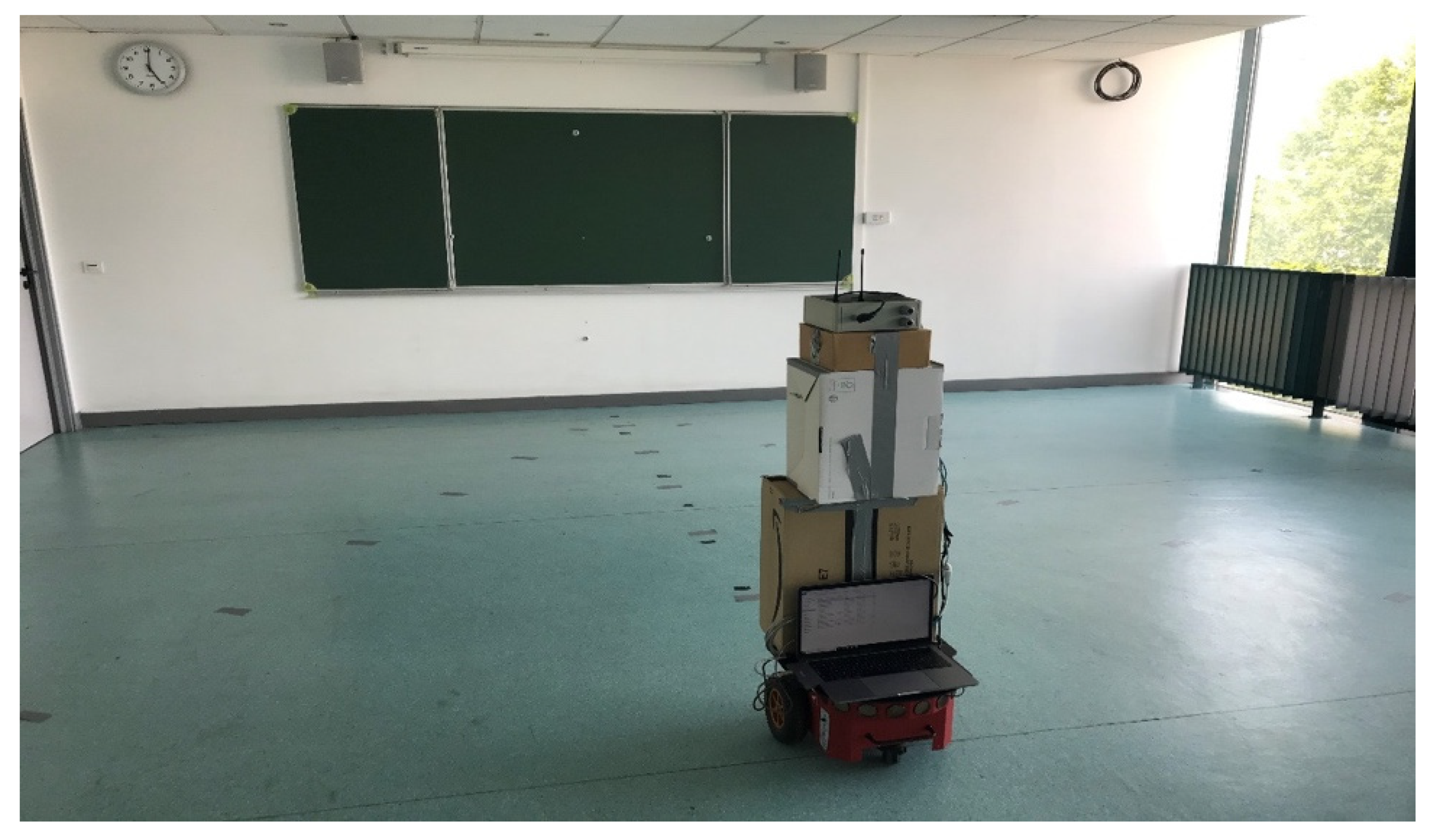
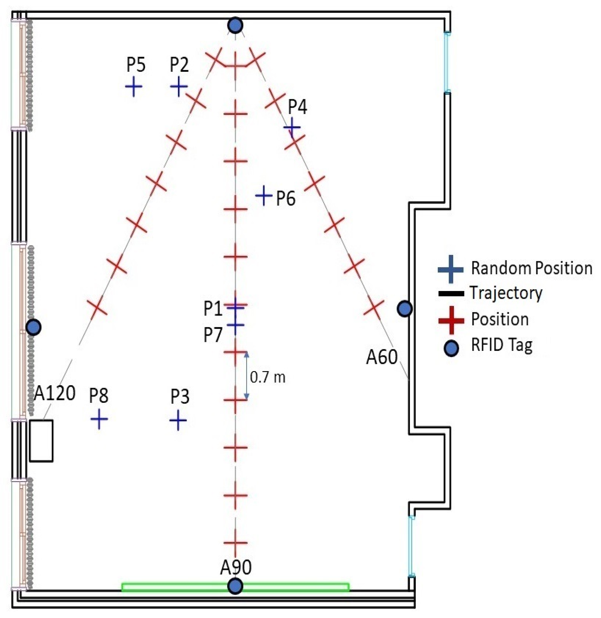
3. Experimental Setup and Localization Processing Details
3.1. Robot’s Displacement Evaluation
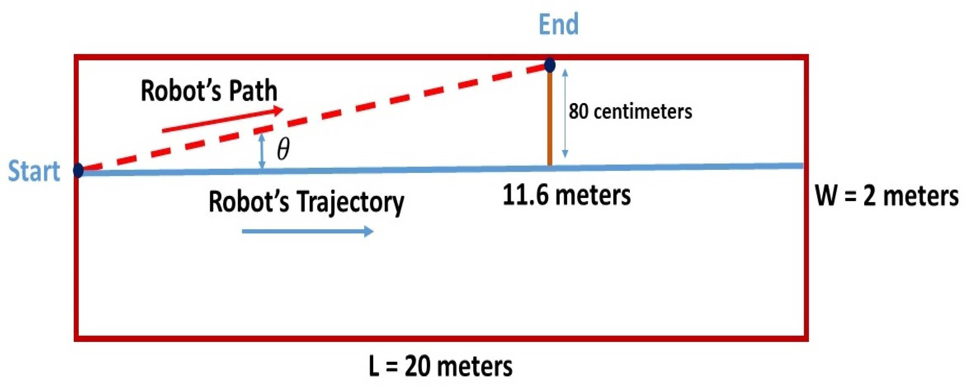
3.1.1. Straight Line Test
3.1.2. Wheel Velocity Test
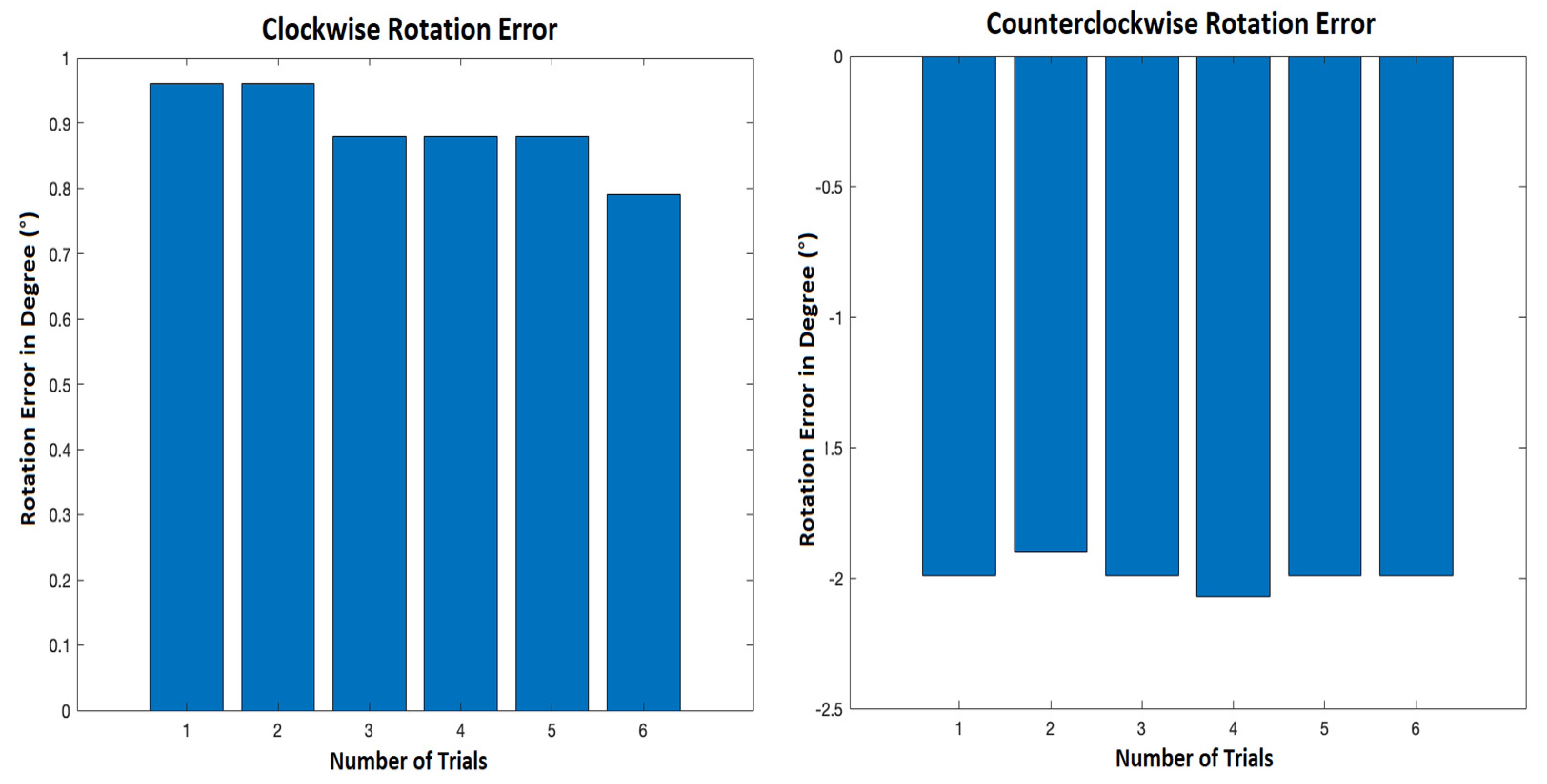
3.1.3. Wheels’ Rotation Test
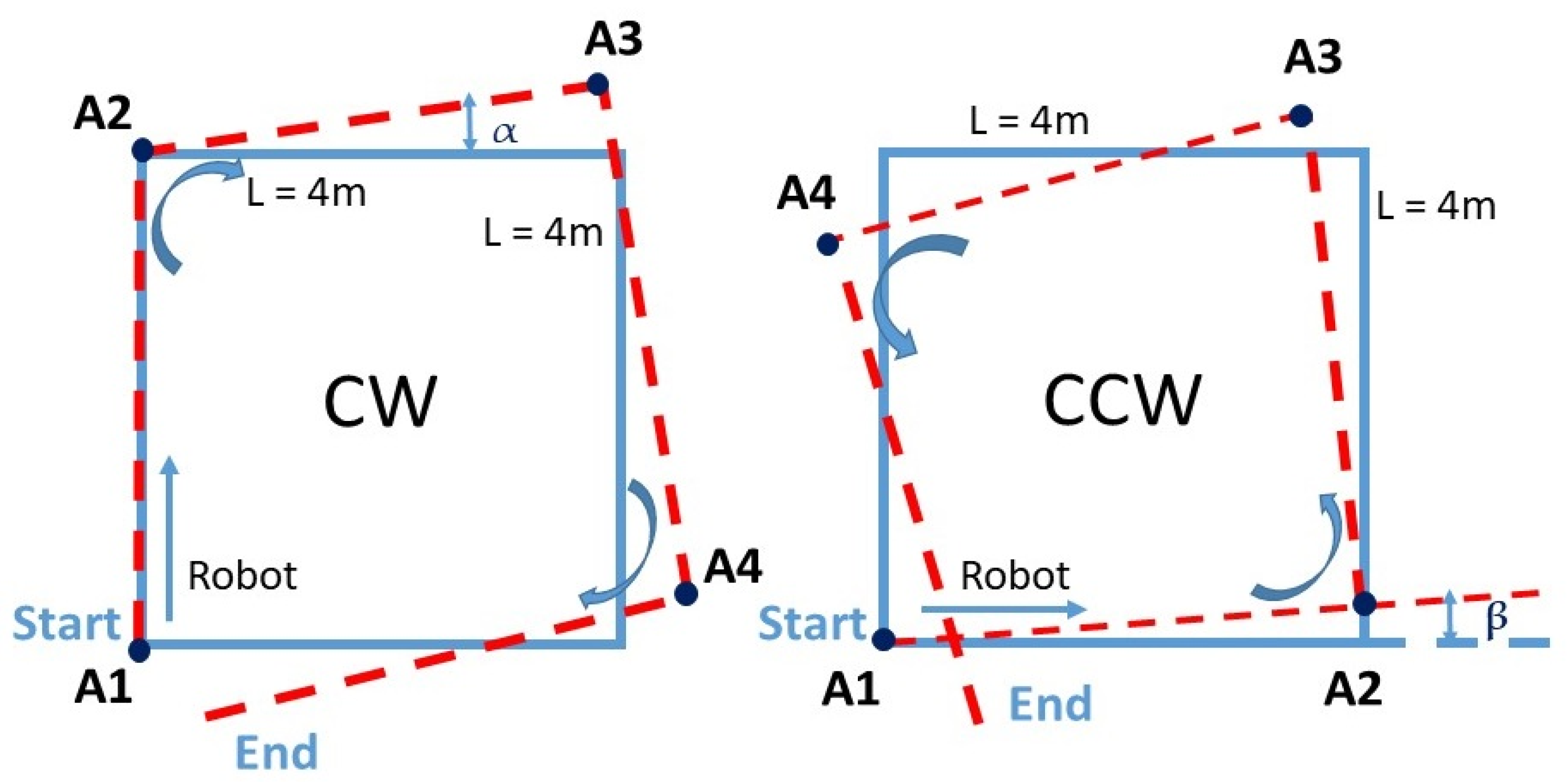
3.1.4. Square Path Test
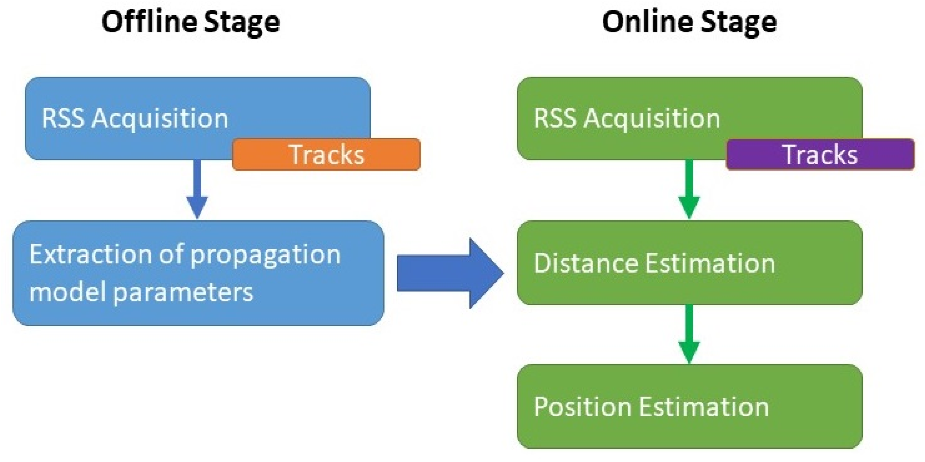
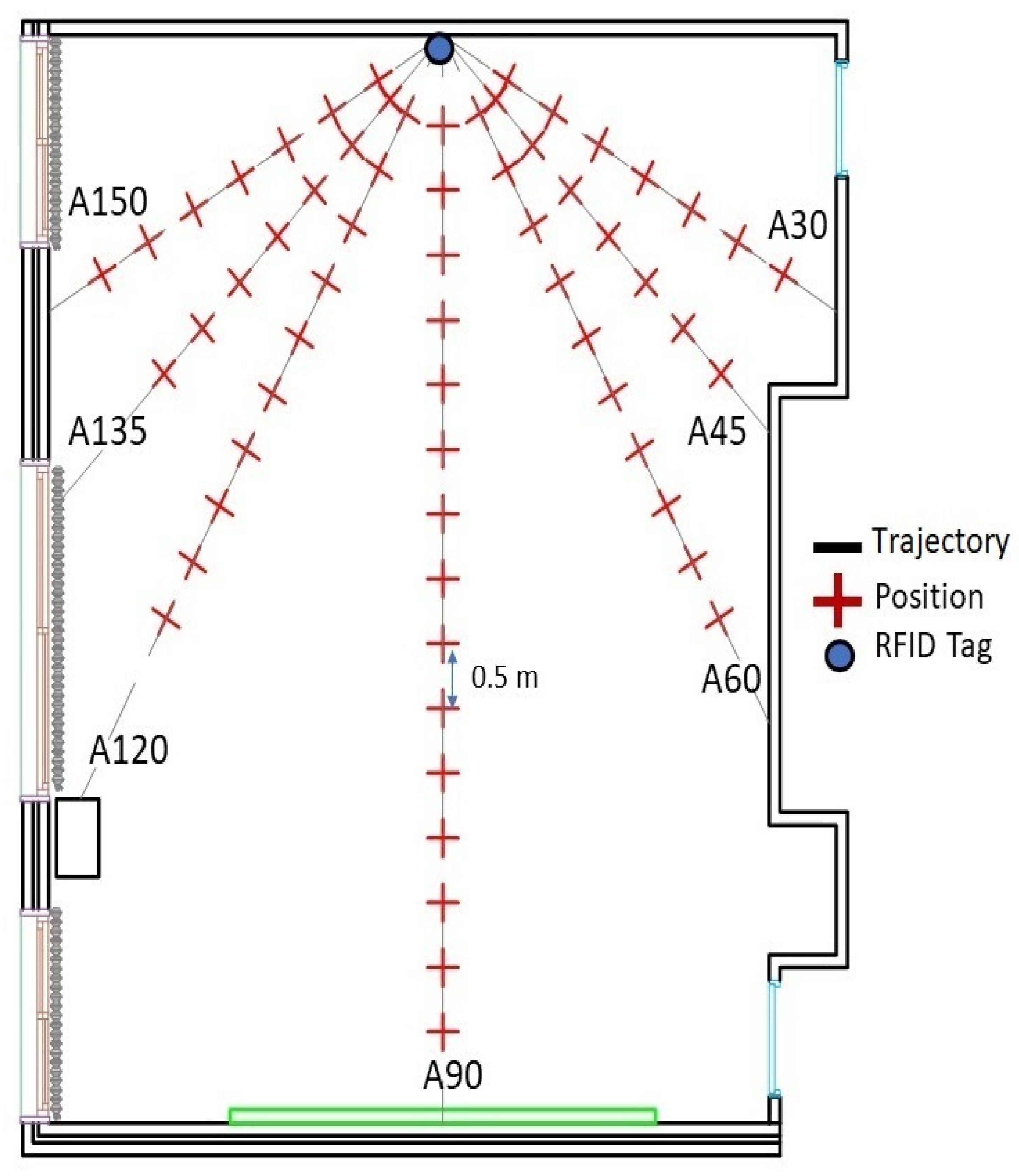
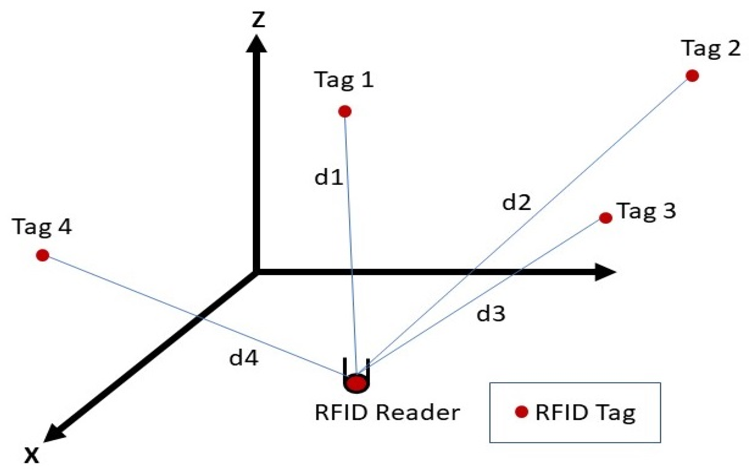
3.2. Localization by Multilateration
3.2.1. Offline Stage—RSS Acquisition
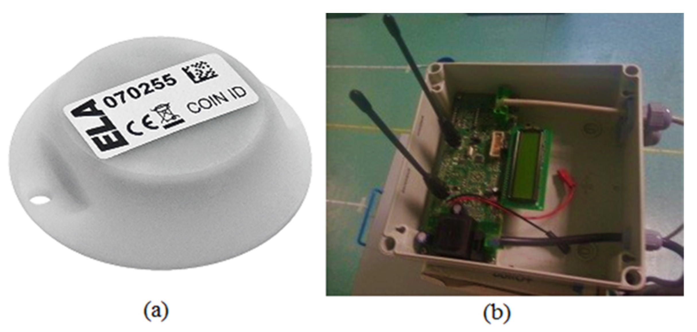
3.2.2. Online Stage—Received Signal Strength Indicators (RSSIs) Acquisition
4. Conclusions
Author Contributions
Funding
Institutional Review Board Statement
Informed Consent Statement
Acknowledgments
Conflicts of Interest
Abbreviations
| RFID | Radio Frequency Identification |
| GNSS | Global Navigation Satellite System |
| RSS | Received Signal Strength |
| WiFi | Wireless Fidelity |
| PDR | Pedestrian Dead Reckoning |
| MM | Magnetic Matching |
| UILoc | Unsupervised Indoor Localization |
| DL | Deep Learning |
| CNN | Convolutional Neural Network |
| AP | Access Point |
| RSSI | Received Signal Strength Indicator |
| KNN | K-Nearest Neighbor |
| SVM | Support Vector Machines |
| RNN | Recurrent Neural Networks |
| GRU | Gate Recurrent Units |
| BLE | Bluetooth Low Energy |
| RP | Reference Point |
| EM | Expectation–Maximization |
| ANOVA | Analysis of Variance |
| SLAM | Simultaneous Localization and Mapping |
| TNN | Tensor Nuclear Norm |
| ASMF | Adaptive signal Mode Fingerprinting |
| SRL-KNN | Soft Range Limited K-Nearest Neighbor |
| PDOA | Phase Difference of Arrival |
| CW | Clockwise |
| CCW | Counterclockwise |
| DOSSOM | Dual One Slope with Second Order Model |
| CDF | Cumulative Distribution Function |
References
- Kolomijeca, A.; López-Salcedo, J.A.; Lohan, E.; Seco-Granados, G. GNSS applications: Personal safety concerns. In Proceedings of the 2016 International Conference on Localization and GNSS (ICL-GNSS), Barcelona, Spain, 28–30 June 2016; pp. 1–5. [Google Scholar] [CrossRef]
- Hameed, A.; Ahmed, H.A. Survey on indoor positioning applications based on different technologies. In Proceedings of the 2018 12th International Conference on Mathematics, Actuarial Science, Computer Science and Statistics (MACS), Karachi, Pakistan, 24–25 November 2018; pp. 1–5. [Google Scholar] [CrossRef]
- Breßler, J.; Reisdorf, P.; Obst, M.; Wanielik, G. GNSS positioning in non-line-of-sight context—A survey. In Proceedings of the 2016 IEEE 19th International Conference on Intelligent Transportation Systems (ITSC), Rio de Janeiro, Brazil, 1–4 November 2016; pp. 1147–1154. [Google Scholar] [CrossRef]
- Marathe, T.; Broumandan, A.; Pirsiavash, A.; Lachapelle, G. Characterization of Range and Time Performance of Indoor GNSS Signals. In Proceedings of the 2018 European Navigation Conference (ENC), Gothenburg, Sweden, 14–17 May 2018; pp. 27–37. [Google Scholar] [CrossRef]
- Hesslein, N.; Wesselhöft, M.; Hinckeldeyn, J.; Kreutzfeldt, J. Industrial Indoor Localization: Improvement of Logistics Processes Using Location Based Services. In Advances in Automotive Production Technology–Theory and Application; Springer: Berlin/Heidelberg, Germany, 2021; pp. 460–467. [Google Scholar]
- Tsai, C.; Hsu, K. An Application of Using Bluetooth Indoor Positioning, Image Recognition and Augmented Reality. In Proceedings of the 2016 IEEE 13th International Conference on e-Business Engineering (ICEBE), Macau, China, 4–6 November 2016; pp. 276–281. [Google Scholar] [CrossRef]
- Birla, S.; Singh, G.; Kumhar, P.; Gunjalkar, K.; Sarode, S.; Choubey, S.; Pawar, M. Disha-Indoor Navigation App. In Proceedings of the 2020 2nd International Conference on Advances in Computing, Communication Control and Networking (ICACCCN), Greater Noida, India, 18–19 December 2020; pp. 517–522. [Google Scholar] [CrossRef]
- Fortes, S.; Aguilar-Garcia, A.; Barco, R.; Barba, F.B.; Fernández-Luque, J.A.; Fernández-Durán, A. Management architecture for location-aware self-organizing LTE/LTE-A small cell networks. IEEE Commun. Mag. 2015, 53, 294–302. [Google Scholar] [CrossRef]
- Fortes, S.; Baena, C.; Villegas, J.; Baena, E.; Asghar, M.Z.; Barco, R. Location-Awareness for Failure Management in Cellular Networks: An Integrated Approach. Sensors 2021, 21, 1501. [Google Scholar] [CrossRef] [PubMed]
- Aguilar-Garcia, A.; Fortes, S.; Molina-García, M.; Sánchez, J.C.; Alonso, J.I.; Garrido, A.; Fernandez-Duran, A.; Barco, R. Location-aware self-organizing methods in femtocell networks. Comput. Netw. 2015, 93, 125–140. [Google Scholar] [CrossRef] [Green Version]
- Aguilar-Garcia, A.; Fortes, S.; Fernandez-Duran, A.; Barco, R. Context-Aware Self-Optimization: Evolution Based on the Use Case of Load Balancing in Small-Cell Networks. IEEE Veh. Technol. Mag. 2016, 11, 86–95. [Google Scholar] [CrossRef]
- Zafari, F.; Gkelias, A.; Leung, K. A Survey of Indoor Localization Systems and Technologies. arXiv 2017, arXiv:1709.01015. [Google Scholar] [CrossRef] [Green Version]
- Aguilar-Garcia, A.; Fortes, S.; Colin, E.; Barco, R. Enhancing localization accuracy with multi-antenna UHF RFID fingerprinting. In Proceedings of the 2015 International Conference on Indoor Positioning and Indoor Navigation (IPIN), Banff, AB, Canada, 13–16 October 2015; pp. 1–9. [Google Scholar] [CrossRef]
- Basri, C.; el Khadimi, A. Survey on indoor localization system and recent advances of WIFI fingerprinting technique. In Proceedings of the 2016 5th International Conference on Multimedia Computing and Systems (ICMCS), Marrakech, Morocco, 29 September–1 October 2016; pp. 253–259. [Google Scholar] [CrossRef]
- García-Paterna, P.J.; Martínez-Sala, A.S.; Sánchez-Aarnoutse, J.C. Empirical Study of a Room-Level Localization System Based on Bluetooth Low Energy Beacons. Sensors 2021, 21, 3665. [Google Scholar] [CrossRef]
- Aguilar-Garcia, A.; Fortes, S.; Colin, E.; Barco, R. Enhancing RFID indoor localization with cellular technologies. EURASIP J. Wirel. Commun. Netw. 2015, 1, 1501. [Google Scholar] [CrossRef] [Green Version]
- Ismail, H.; Kitagawa, H.; Tasaki, R.; Terashima, K. WiFi RSS fingerprint database construction for mobile robot indoor positioning system. In Proceedings of the 2016 IEEE International Conference on Systems, Man, and Cybernetics (SMC), Budapest, Hungary, 9–12 October 2016; pp. 001561–001566. [Google Scholar]
- Seco, F.; Jimenez, A.R. Autocalibration of a wireless positioning network with a FastSLAM algorithm. In Proceedings of the International Conference on Indoor Positioning and Indoor Navigation, Sapporo, Japan, 18–21 September 2017; pp. 1–8. [Google Scholar]
- Roy, P.; Chowdhury, C. A Survey of Machine Learning Techniques for Indoor Localization and Navigation Systems. J. Intell. Robot. Syst. 2021, 101, 1–34. [Google Scholar] [CrossRef]
- Hatem, E.; Colin, E.; Abou-Chakra, S.; El-Hassan, B.; Laheurte, J.-M. New Empirical Indoor Path Loss Model using Active UHF-RFID Tags for Localization Purposes. In Proceedings of the 2018 IEEE International Conference on RFID Technology & Application (RFID-TA), Macau, China, 26–28 September 2018; pp. 1–6. [Google Scholar]
- Ni, L.M.; Liu, Y.; Lau, Y.C.; Patil, A.P. LANDMARC: Indoor location sensing using active RFID. In Proceedings of the First IEEE International Conference on Pervasive Computing and Communications (PerCom 2003), Fort Worth, TX, USA, 21–25 March 2003; pp. 407–415. [Google Scholar]
- Huang, Y.; Lv, S.; He, Y.; Huang, J. An Isosceles Triangular Placement of Reference Tags for RFID Indoor Location System. Chin. J. Electron. 2011, 20, 504–510. [Google Scholar]
- Wu, J.; Zhu, M.; Xiao, B.; Qiu, Y. The Improved Fingerprint-Based Indoor Localization with RFID/PDR/MM Technologies. In Proceedings of the 2018 IEEE 24th International Conference on Parallel and Distributed Systems (ICPADS), Singapore, 11–13 December 2018; pp. 878–885. [Google Scholar]
- Chen, J.; Zhang, Y.; Xue, W. Unsupervised indoor localization based on Smartphone Sensors, iBeacon and Wi-Fi. Sensors 2018, 18, 1378. [Google Scholar] [CrossRef] [PubMed] [Green Version]
- Mittal, A.; Tiku, S.; Pasricha, S. Adapting convolutional neural networks for indoor localization with smart mobile devices. In Proceedings of the 2018 on Great Lakes Symposium on VLSI, Chicago, IL, USA, 23–25 May 2018; pp. 117–122. [Google Scholar]
- Sinha, R.S.; Hwang, S.H. Sinha Comparison of CNN applications for RSSI-based fingerprint indoor localization. Electronics 2019, 8, 989. [Google Scholar] [CrossRef] [Green Version]
- Liu, Z.; Dai, B.; Wan, X.; Li, X. Hybrid wireless fingerprint indoor localization method based on a convolutional neural network. Sensors 2019, 19, 4597. [Google Scholar] [CrossRef] [Green Version]
- Carvalho, E.C.; Ferreira, B.V.; Filho, P.R.G.; Gomes, P.H.; Freitas, G.M.; Vargas, P.A.; Pessin, G. Towards a smart fault tolerant indoor localization system through recurrent neural networks. In Proceedings of the 2019 IEEE International Joint Conference on Neural Networks (IJCNN), Budapest, Hungary, 14–19 July 2019; pp. 1–7. [Google Scholar]
- Li, M.; Zhao, L.; Tan, D.; Tong, X. BLE fingerprint indoor localization algorithm based on eight-neighborhood template matching. Sensors 2019, 19, 4859. [Google Scholar] [CrossRef] [Green Version]
- González, J.L.S.; Morillo, L.M.S.; Álvarez-García, J.A.; Ros, F.E.D.S.; Ruiz, A.R.J. Energy-efficient indoor localization WiFi-fingerprint system: An experimental study. IEEE Access 2019, 7, 162664–162682. [Google Scholar] [CrossRef]
- Olesiński, A.; Piotrowski, Z. An Adaptive Energy Saving Algorithm for an RSSI-Based Localization System in Mobile Radio Sensors. Sensors 2021, 21, 3987. [Google Scholar] [CrossRef]
- Zhao, F.; Huang, T.; Wang, D. A probabilistic approach for wifi fingerprint localization in severely dynamic indoor environments. IEEE Access 2019, 7, 116348–116357. [Google Scholar] [CrossRef]
- Wang, W.; Marelli, D.; Fu, M. Fingerprinting-based indoor localization using interpolated preprocessed CSI phases and Bayesian tracking. Sensors 2020, 20, 2854. [Google Scholar] [CrossRef]
- Thewan, T.; Ismail, A.H.; Panya, M.; Terashima, K.T. Assessment of WiFi RSS using design of experiment for mobile robot wireless positioning system. In Proceedings of the 2016 19th International Conference on Information Fusion (FUSION), Heidelberg, Germany, 5–8 July 2016. [Google Scholar]
- Nastac, D.; Lehan, E.; Iftimie, F.A.; Arsene, O.; Cramariuc, B. Automatic Data Acquisition with Robots for Indoor Fingerprinting. In Proceedings of the 2018 International Conference on Communications (COMM), Bucharest, Hungary, 14–16 June 2018; pp. 321–326. [Google Scholar]
- Yan, H.; Peng, T.; Liu, H.; Ding, Y. Indoor Position Method of Industrial Robot Based on Wifi Fingerprint Position Technology. In Proceedings of the 2019 1st International Conference on Industrial Artificial Intelligence (IAI), Shenyang, China, 22–26 July 2019; pp. 1–6. [Google Scholar]
- Luo, R.C.; Hsiao, T.J. Dynamic wireless indoor localization incorporating with an autonomous mobile robot based on an adaptive signal model fingerprinting approach. IEEE Trans. Ind. Electron. 2018, 66, 1940–1951. [Google Scholar] [CrossRef]
- Serif, T.; Perente, O.K.; Dalan, Y. RoboMapper: An Automated Signal Mapping Robot for RSSI Fingerprinting. In Proceedings of the 2019 7th International Conference on Future Internet of Things and Cloud (FiCloud), Istanbul, Turkey, 26–28 August 2019; pp. 364–370. [Google Scholar]
- Trogh, J.; Joseph, W.; Martens, L.; Plets, D. An unsupervised learning technique to optimize radio maps for indoor localization. Sensors 2019, 19, 752. [Google Scholar] [CrossRef] [Green Version]
- Sinha, R.S.; Hwang, S.H. Improved RSSI-based data augmentation technique for fingerprint indoor localization. Electronics 2020, 9, 851. [Google Scholar] [CrossRef]
- Hoang, M.T.; Zhu, Y.; Yuen, B.; Reese, T.; Dong, X.; Lu, T.; Xie, M. A soft range limited K-Nearest Neighbors algorithm for indoor localization enhancement. IEEE Sens. J. 2018, 18, 10208–10216. [Google Scholar] [CrossRef] [Green Version]
- Zhang, Y.; Gong, X.; Liu, K.; Zhang, S. Localization and Tracking of an Indoor Autonomous Vehicle Based on the Phase Difference of Passive UHF RFID Signals. Sensors 2021, 21, 3286. [Google Scholar] [CrossRef]
- Loganathan, A.; Ahmad, N.S.; Goh, P. Self-adaptive filtering approach for improved indoor localization of a mobile node with zigbee-based RSSI and odometry. Sensors 2019, 19, 4748. [Google Scholar] [CrossRef] [PubMed] [Green Version]
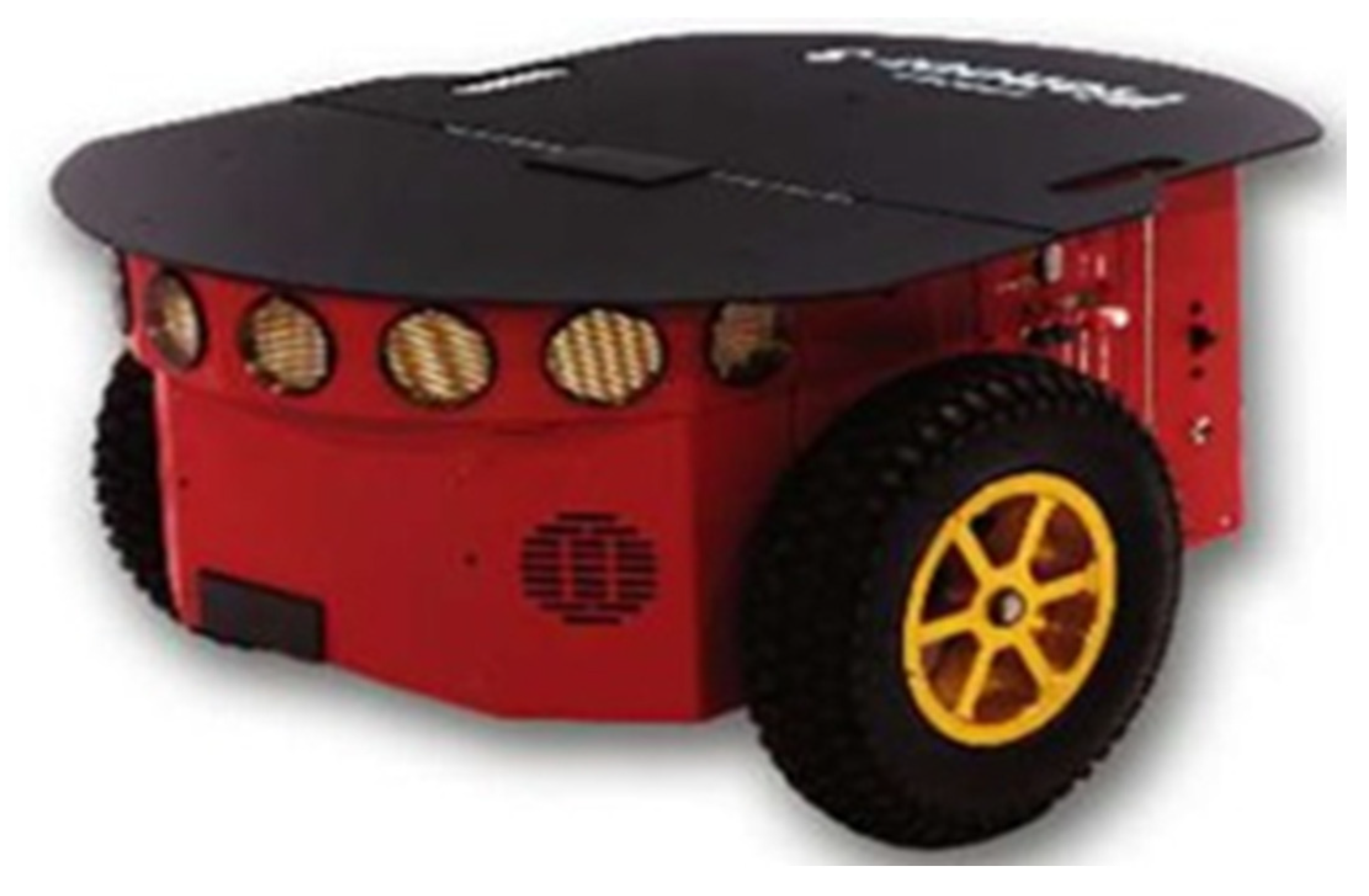
- Adept MobileRobots. Pioneer 3-DX Datasheet. 2011. Available online: http://www.mobilerobots.com/Libraries/Downloads/Pioneer3DX-P3DX-RevA.sflb.ashx (accessed on 30 April 2021).
- Park, S.; Hashimoto, S. Autonomous Mobile Robot Navigation Using Passive RFID in Indoor Environment. IEEE Trans. Ind. Electron. 2009, 56, 2366–2373. [Google Scholar] [CrossRef]
- Borenstein, J.; Feng, L. UMBmark—A Method for Measuring, Comparing, and Correcting Dead-Reckoning Errors in Mobile Robots, 2nd ed.; Tech. Report UM-MEAM-94-22; University of Michigan: Ann Arbor, MI, USA, 1994. [Google Scholar]
- Sadowski, S.; Spachos, P. Rssi-based indoor localization with the internet of things. IEEE Access 2018, 6, 30149–30161. [Google Scholar] [CrossRef]
- Ela Innovation, S.A. Ela Innovation Active RFID Tag and Reader Manufacturer. Available online: https://elainnovation.com/ (accessed on 21 April 2021).
- Fornaser, A.; Maule, L.; Luchetti, A.; Bosetti, P.; de Cecco, M. Self-Weighted Multilateration for Indoor Positioning Systems. Sensors 2019, 19, 872. [Google Scholar] [CrossRef] [Green Version]


| Number of Tests | Test 1 | Test 2 | Test 3 | Mean Deviation (cm) |
|---|---|---|---|---|
| Deviation/1 m [cm] | 6.780 | 6.754 | 6.724 | 6.753 |
| Number of Tests | Test 1 | Test 2 | Test 3 |
|---|---|---|---|
| (mm/s) | 0.0419 | 0.0027 | 0.0297 |
| Angle | A1 | A2 | A3 | A4 |
|---|---|---|---|---|
| Clockwise (α) | 90.1° | 93.6° | 92.4° | 88.4° |
| Counterclockwise (β) | 88.11° | 88.66° | 98.33° | 81.11° |
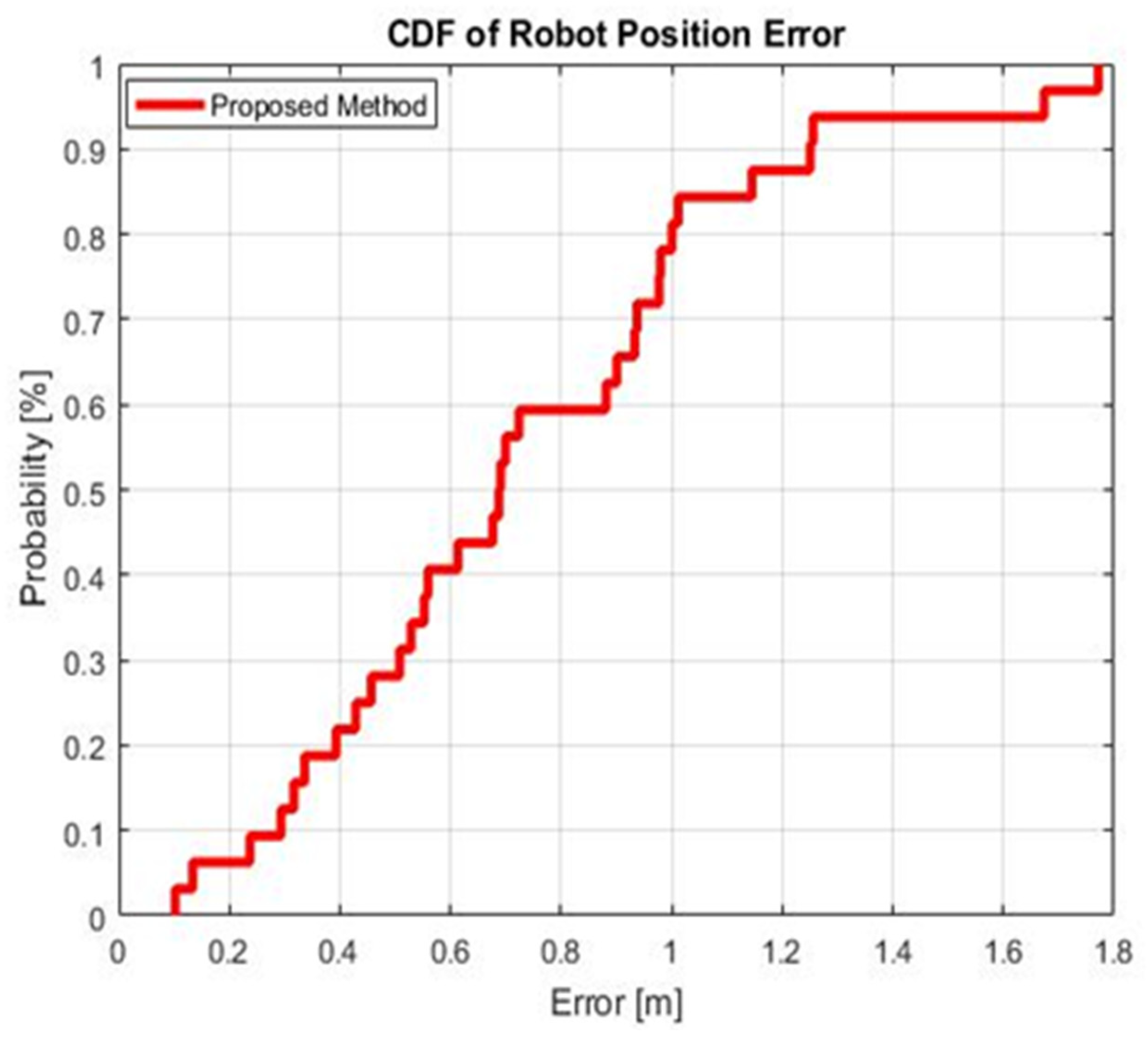
| Algorithms | 50% | 90% | Min | Max | Std |
|---|---|---|---|---|---|
| Accuracy (m) | 0.7 | 1.22 | 0.1 | 1.75 | 0.42 |
Publisher’s Note: MDPI stays neutral with regard to jurisdictional claims in published maps and institutional affiliations. |
© 2021 by the authors. Licensee MDPI, Basel, Switzerland. This article is an open access article distributed under the terms and conditions of the Creative Commons Attribution (CC BY) license (https://creativecommons.org/licenses/by/4.0/).
Share and Cite
Hatem, E.; Fortes, S.; Colin, E.; Abou-Chakra, S.; Laheurte, J.-M.; El-Hassan, B. Accurate and Low-Complexity Auto-Fingerprinting for Enhanced Reliability of Indoor Localization Systems. Sensors 2021, 21, 5346. https://doi.org/10.3390/s21165346
Hatem E, Fortes S, Colin E, Abou-Chakra S, Laheurte J-M, El-Hassan B. Accurate and Low-Complexity Auto-Fingerprinting for Enhanced Reliability of Indoor Localization Systems. Sensors. 2021; 21(16):5346. https://doi.org/10.3390/s21165346
Chicago/Turabian StyleHatem, Elias, Sergio Fortes, Elizabeth Colin, Sara Abou-Chakra, Jean-Marc Laheurte, and Bachar El-Hassan. 2021. "Accurate and Low-Complexity Auto-Fingerprinting for Enhanced Reliability of Indoor Localization Systems" Sensors 21, no. 16: 5346. https://doi.org/10.3390/s21165346