
Identification of Ground Fissure Development in a Semi-Desert Aeolian Sand Area Induced from Coal Mining: Utilizing UAV Images and Deep Learning Techniques

Abstract
:1. Introduction
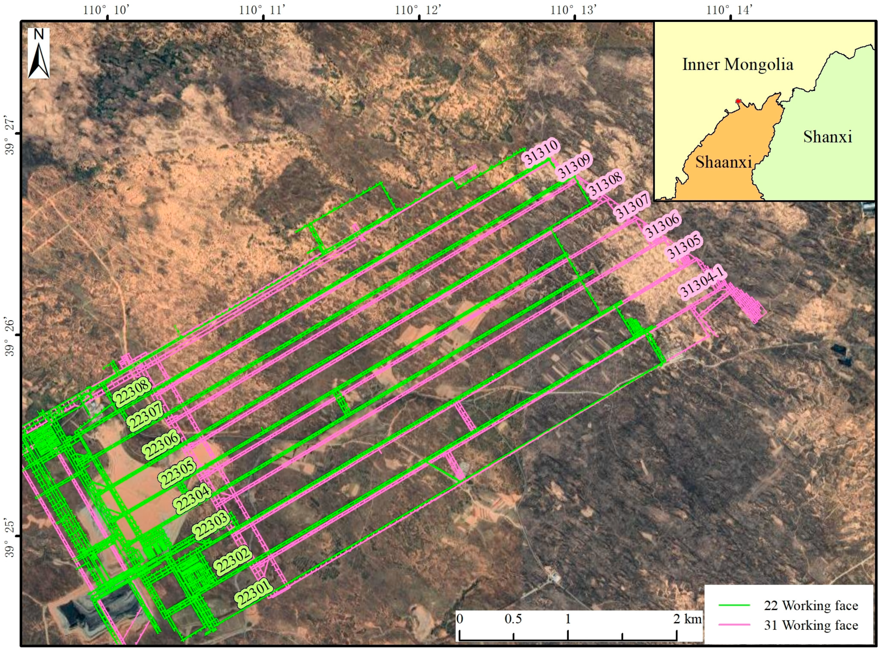
2. Study Area
3. Automatic Fissures Recognition from Aerial Images
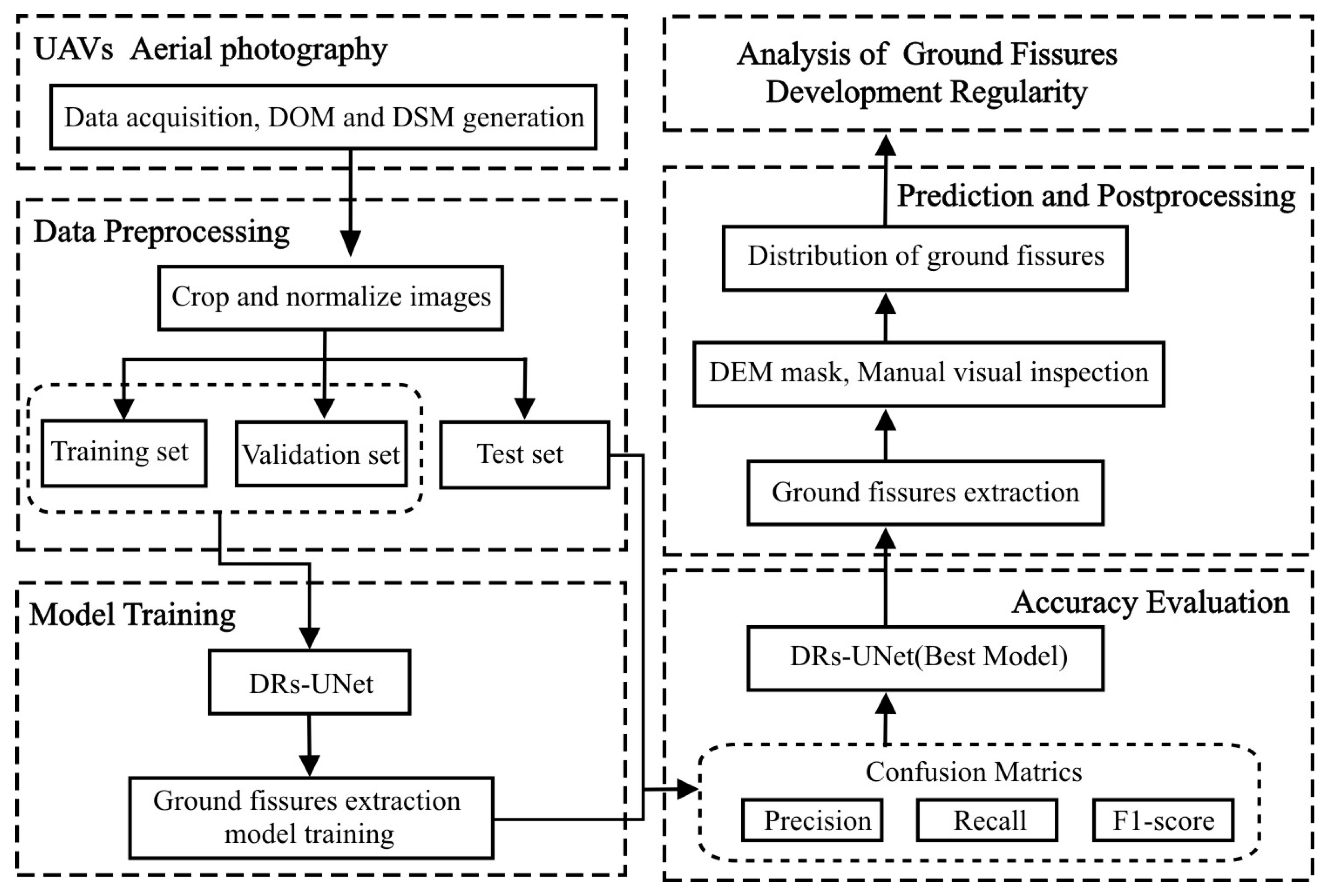
3.1. Overall Process of Automatic Fissure Identification in UAV Flight Images
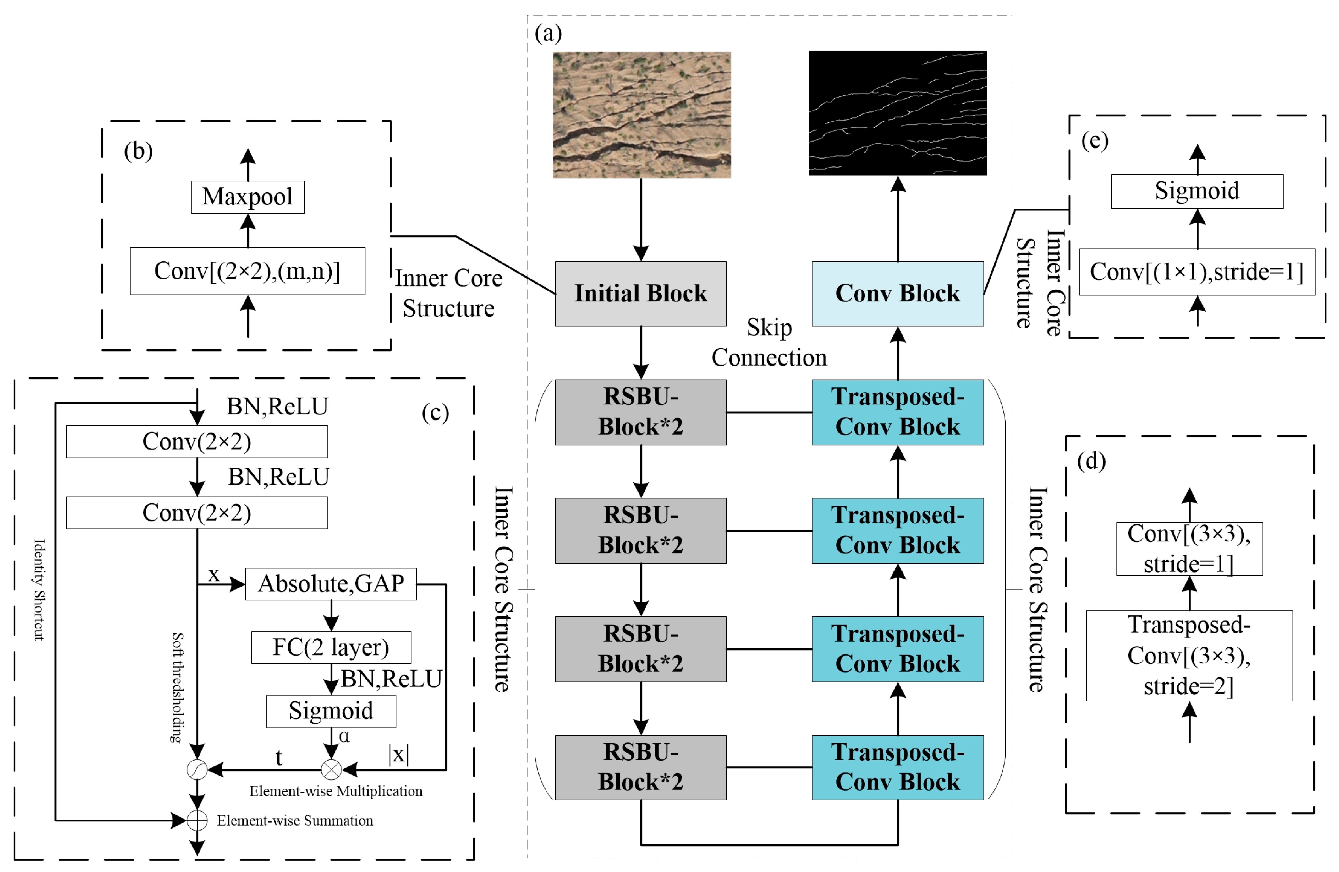
3.2. The Methodology of the Deep Residual Shrinkage U-Net (DRs-UNet)
3.3. Evaluation of Ground Fissure Identifications
3.4. Result of Ground Fissure Identifications
4. Fissures Distribution Patterns
4.1. Introduction to the Working Methods of Fully Mechanized Coal Mining
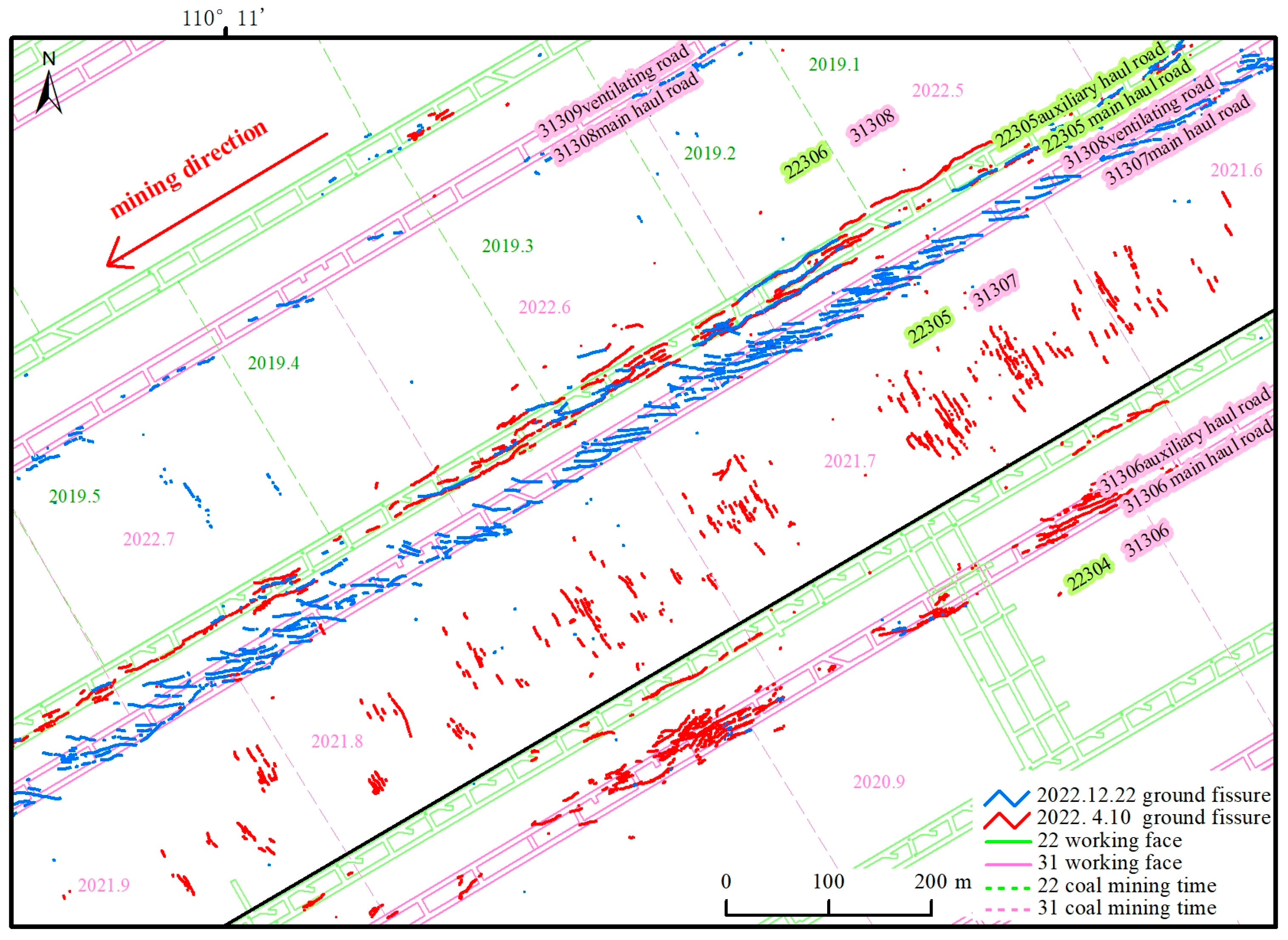
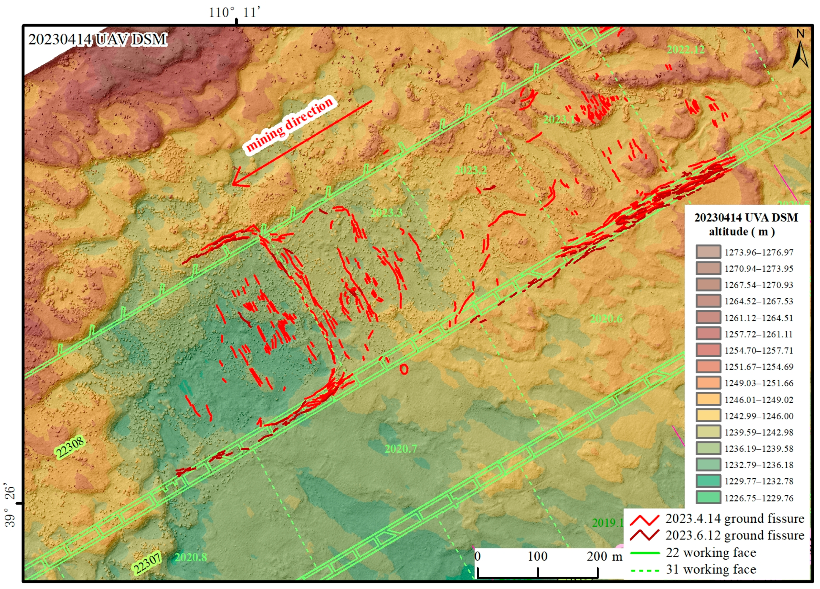
4.2. Spatial Distribution Pattern of Ground Fissures
4.2.1. The Open-Cut Ground Fissures
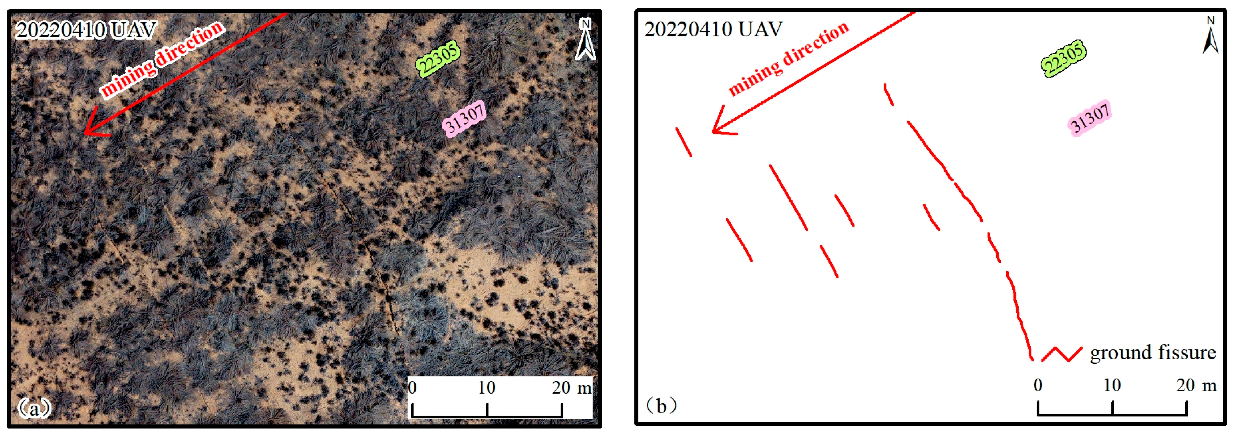
4.2.2. The Ground Fissures Developed at the Central Collapse Zone near the Working Face
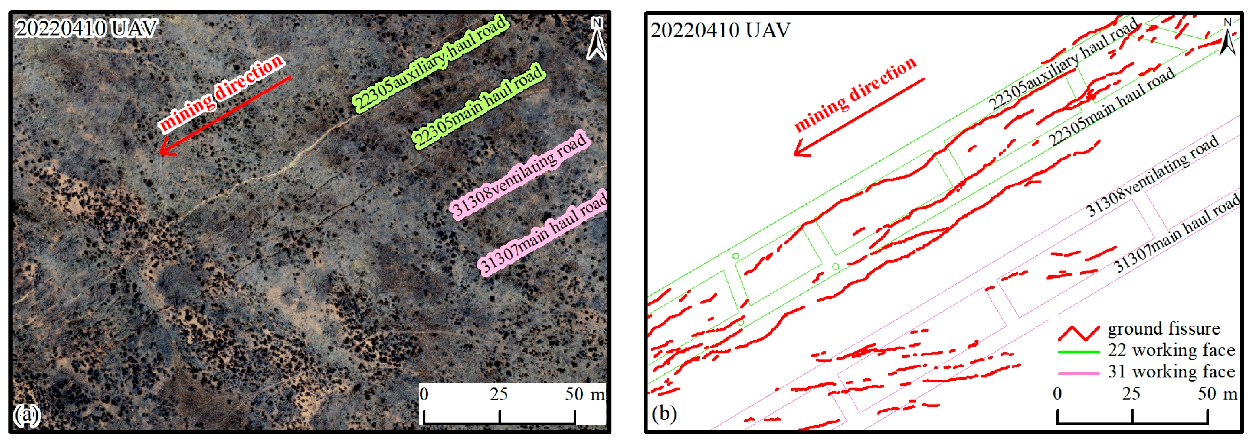
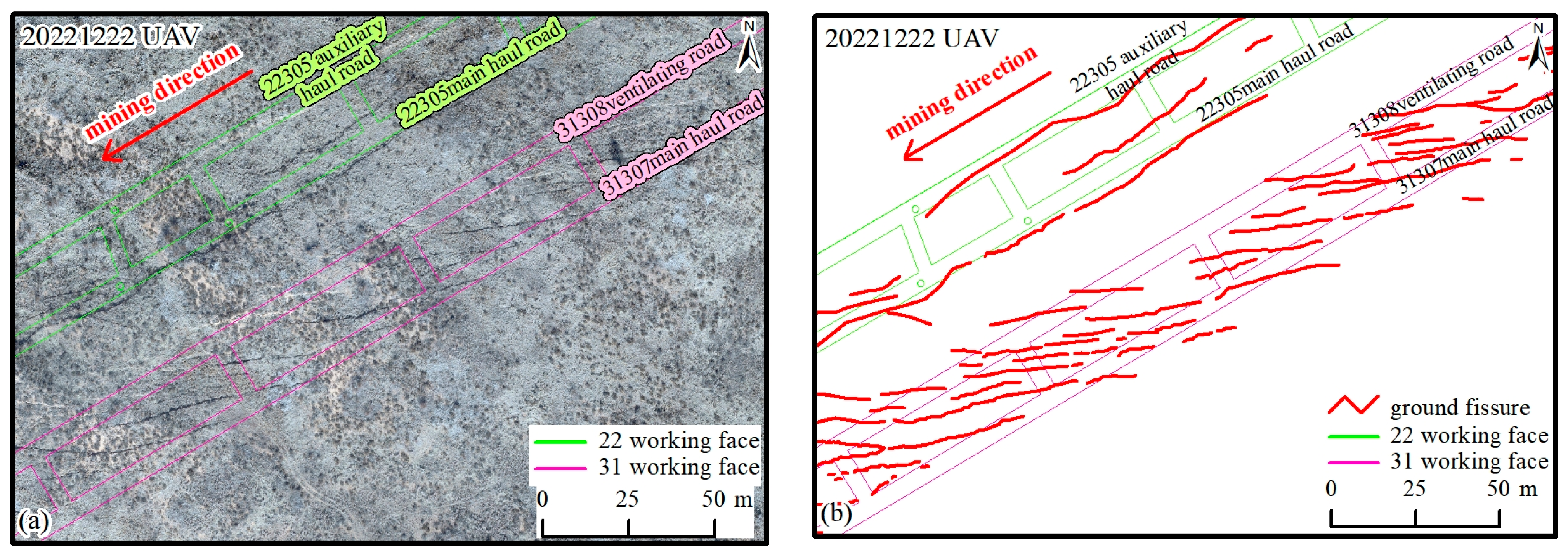
4.2.3. The Parallel and Oblique Ground Fissures above the Roadway
4.2.4. The Reverse-“C”-Shaped Ground Fissures within the Weak Overburden Zone
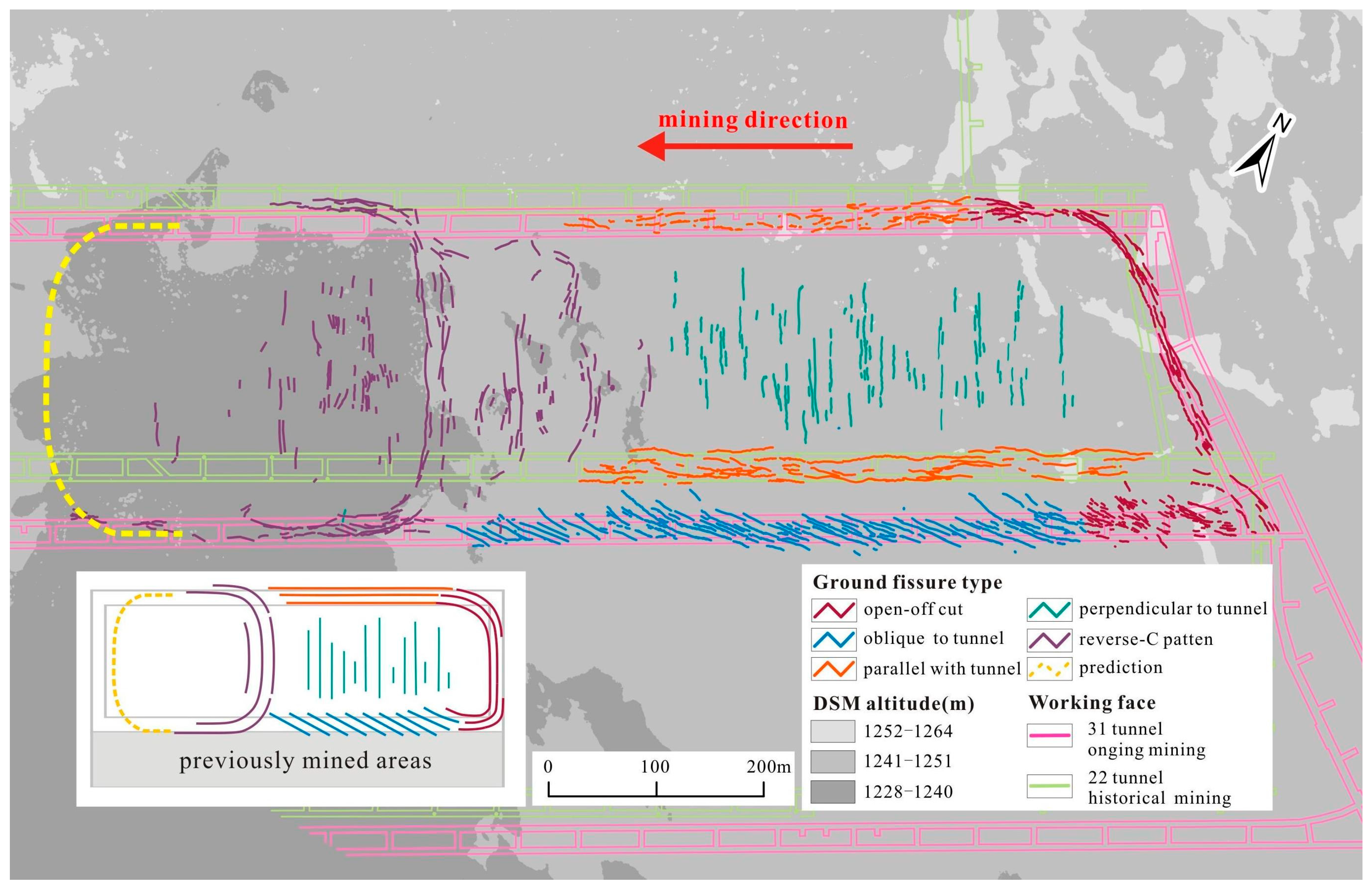
4.3. Classification and Comparison of Ground Fissure Development Patterns
5. Discussion
5.1. Automatic Identification of Coal Mining Fissures in Semi-Desert Aeolian Sand Areas
5.2. Summary of Patterns of Coal Mining-Induced Ground Fissures
6. Conclusions
Author Contributions
Funding
Data Availability Statement
Conflicts of Interest
References
- Hu, Z.-Q.; Wang, X.J.; He, A.-M. Distribution Characteristic and Development Rules of Ground Fissures Due to Coal Mining in Windy and Sandy Region. J. China Coal Soc. 2014, 39, 11–18. [Google Scholar]
- Yang, X.; Wen, G.; Dai, L.; Sun, H.; Li, X. Ground Subsidence and Surface Cracks Evolution from Shallow-Buried Close-Distance Multi-Seam Mining: A Case Study in Bulianta Coal Mine. Rock Mech. Rock Eng. 2019, 52, 2835–2852. [Google Scholar] [CrossRef]
- Zhou, D.; Wu, K.; Bai, Z.; Hu, Z.; Li, L.; Xu, Y.; Diao, X. Formation and Development Mechanism of Ground Crack Caused by Coal Mining: Effects of Overlying Key Strata. Bull. Eng. Geol. Environ. 2019, 78, 1025–1044. [Google Scholar] [CrossRef]
- Donnelly, L.J. A Review of Coal Mining Induced Fault Reactivation in Great Britain. Q. J. Eng. Geol. Hydrogeol. 2006, 39, 5–50. [Google Scholar] [CrossRef]
- Yang, D.; Qiu, H.; Ma, S.; Liu, Z.; Du, C.; Zhu, Y.; Cao, M. Slow Surface Subsidence and Its Impact on Shallow Loess Landslides in a Coal Mining Area. Catena 2022, 209, 105830. [Google Scholar] [CrossRef]
- Jiang, L.; Lin, H.; Ma, J.; Kong, B.; Wang, Y. Potential of Small-Baseline SAR Interferometry for Monitoring Land Subsidence Related to Underground Coal Fires: Wuda (Northern China) Case Study. Remote Sens. Environ. 2011, 115, 257–268. [Google Scholar] [CrossRef]
- Bi, Y.; Zhang, J.; Song, Z.; Wang, Z.; Qiu, L.; Hu, J.; Gong, Y. Arbuscular Mycorrhizal Fungi Alleviate Root Damage Stress Induced by Simulated Coal Mining Subsidence Ground Fissures. Sci. Total Environ. 2019, 652, 398–405. [Google Scholar] [CrossRef] [PubMed]
- Wang, C.; Zhang, C.; Zhao, X.; Liao, L.; Zhang, S. Dynamic Structural Evolution of Overlying Strata during Shallow Coal Seam Longwall Mining. Int. J. Rock Mech. Min. Sci. 2018, 103, 20–32. [Google Scholar] [CrossRef]
- Zhao, K.; Xu, N.; Mei, G.; Tian, H. Predicting the Distribution of Ground Fissures and Water-Conducted Fissures Induced by Coal Mining: A Case Study. SpringerPlus 2016, 5, 977. [Google Scholar] [CrossRef]
- Li, X.; Cao, Z.; Xu, Y. Characteristics and Trends of Coal Mine Safety Development. Energy Sources Part A Recovery Util. Environ. Eff. 2020, 1–19. [Google Scholar] [CrossRef]
- Li, L.; Wu, K.; Hu, Z.; Xu, Y.; Zhou, D. Analysis of Developmental Features and Causes of the Ground Cracks Induced by Oversized Working Face Mining in an Aeolian Sand Area. Environ. Earth Sci. 2017, 76, 135. [Google Scholar] [CrossRef]
- Liu, C.; Zhou, F.; Gao, J.; Wang, J. Some Problems of GPS RTK Technique Application to Mining Subsidence Monitoring. Int. J. Min. Sci. Technol. 2012, 22, 223–228. [Google Scholar] [CrossRef]
- Fu, Y.; Shang, J.; Hu, Z.; Li, P.; Yang, K.; Chen, C.; Guo, J.; Yuan, D. Ground Fracture Development and Surface Fracture Evolution in N00 Method Shallowly Buried Thick Coal Seam Mining in an Arid Windy and Sandy Area: A Case Study of the Ningtiaota Mine (China). Energies 2021, 14, 7712. [Google Scholar] [CrossRef]
- Nex, F.; Remondino, F. UAV for 3D Mapping Applications: A Review. Appl. Geomat. 2014, 6, 1–15. [Google Scholar] [CrossRef]
- Zhang, F.; Hu, Z.; Fu, Y.; Yang, K.; Wu, Q.; Feng, Z. A New Identification Method for Surface Cracks from UAV Images Based on Machine Learning in Coal Mining Areas. Remote Sens. 2020, 12, 1571. [Google Scholar] [CrossRef]
- Ren, H.; Zhao, Y.; Xiao, W.; Hu, Z. A Review of UAV Monitoring in Mining Areas: Current Status and Future Perspectives. Int. J. Coal Sci. Technol. 2019, 6, 320–333. [Google Scholar] [CrossRef]
- Kundal, S.; Chowdhury, A.; Bhardwaj, A.; Garg, P.K.; Mishra, V. GeoBIA-Based Semi-Automated Landslide Detection Using UAS Data: A Case Study of Uttarakhand Himalayas. In Proceedings of the SPIE Future Sensing Technologies 2023, Yokohama, Japan, 18–21 April 2023; Matoba, O., Valenta, C.R., Shaw, J.A., Eds.; SPIE: Bellingham, WA, USA, 2023; p. 79. [Google Scholar]
- Mishra, V.; Avtar, R.; Prathiba, A.P.; Mishra, P.K.; Tiwari, A.; Sharma, S.K.; Singh, C.H.; Chandra Yadav, B.; Jain, K. Uncrewed Aerial Systems in Water Resource Management and Monitoring: A Review of Sensors, Applications, Software, and Issues. Adv. Civ. Eng. 2023, 2023, 3544724. [Google Scholar] [CrossRef]
- Minh, D.T.; Dung, N.B. Applications of UAVs in Mine Industry: A Scoping Review. J. Sustain. Min. 2023, 22, 128–145. [Google Scholar] [CrossRef]
- Zhang, F.; Hu, Z.; Liang, Y.; Li, Q. Evaluation of Surface Crack Development and Soil Damage Based on UAV Images of Coal Mining Areas. Land 2023, 12, 774. [Google Scholar] [CrossRef]
- Fu, Y.; Wu, Y.; Yin, X.; Zhang, Y. Mapping Mining-Induced Ground Fissures and Their Evolution Using UAV Photogrammetry. Front. Earth Sci. 2023, 11, 1260913. [Google Scholar] [CrossRef]
- Jiang, X.; Mao, S.; Li, M.; Liu, H.; Zhang, H.; Fang, S.; Yuan, M.; Zhang, C. MFPA-Net: An Efficient Deep Learning Network for Automatic Ground Fissures Extraction in UAV Images of the Coal Mining Area. Int. J. Appl. Earth Obs. Geoinf. 2022, 114, 103039. [Google Scholar] [CrossRef]
- Fan, L.; Zhang, X.; Xiang, M.; Zhang, H.; Shen, T.; Lin, P. Characteristics of Ground Fissure Development in High Intensity Mining Area of Shallow Seam in Yushenfu Coal Field. China Coal Soc. 2015, 40, 1442–1447. [Google Scholar]
- Ma, Z.; Mei, G. Deep Learning for Geological Hazards Analysis: Data, Models, Applications, and Opportunities. Earth-Sci. Rev. 2021, 223, 103858. [Google Scholar] [CrossRef]
- Chen, X.; Yao, X.; Zhou, Z.; Liu, Y.; Yao, C.; Ren, K. DRs-UNet: A Deep Semantic Segmentation Network for the Recognition of Active Landslides from InSAR Imagery in the Three Rivers Region of the Qinghai–Tibet Plateau. Remote Sens. 2022, 14, 1848. [Google Scholar] [CrossRef]
- Long, J.; Shelhamer, E.; Darrell, T. Fully Convolutional Networks for Semantic Segmentation. In Proceedings of the IEEE Conference on Computer Vision and Pattern Recognition (CVPR), Boston, MA, USA, 7–12 June 2015. [Google Scholar]
- Badrinarayanan, V.; Kendall, A.; Cipolla, R. SegNet: A Deep Convolutional Encoder-Decoder Architecture for Image Segmentation. IEEE Trans. Pattern Anal. Mach. Intell. 2017, 39, 2481–2495. [Google Scholar] [CrossRef]
- Minaee, S.; Boykov, Y.; Porikli, F.; Plaza, A.; Kehtarnavaz, N.; Terzopoulos, D. Image Segmentation Using Deep Learning: A Survey. IEEE Trans. Pattern Anal. Mach. Intell. 2021, 44, 3523–3542. [Google Scholar] [CrossRef]
- He, K.; Zhang, X.; Ren, S.; Sun, J. Deep Residual Learning for Image Recognition. In Proceedings of the IEEE Conference on Computer Vision and Pattern Recognition (CVPR), Las Vegas, NV, USA, 27–30 June 2016; pp. 770–778. [Google Scholar]
- Ronneberger, O.; Fischer, P.; Brox, T. U-Net: Convolutional Networks for Biomedical Image Segmentation. In Medical Image Computing and Computer-Assisted Intervention—MICCAI 2015; Springer: Cham, Switzerland, 2015. [Google Scholar]
- Zhao, M.; Zhong, S.; Fu, X.; Tang, B.; Pecht, M. Deep Residual Shrinkage Networks for Fault Diagnosis. IEEE Trans. Ind. Inform. 2019, 16, 4681–4690. [Google Scholar] [CrossRef]
- Shi, Y.; Cui, L.; Qi, Z.; Meng, F.; Chen, Z. Automatic Road Crack Detection Using Random Structured Forests. IEEE Trans. Intell. Transport. Syst. 2016, 17, 3434–3445. [Google Scholar] [CrossRef]
- Al-Rawabdeh, A.; He, F.; Moussa, A.; El-Sheimy, N.; Habib, A. Using an Unmanned Aerial Vehicle-Based Digital Imaging System to Derive a 3D Point Cloud for Landslide Scarp Recognition. Remote Sens. 2016, 8, 95. [Google Scholar] [CrossRef]
- Yang, K.; Hu, Z.; Liang, Y.; Fu, Y.; Yuan, D.; Guo, J.; Li, G.; Li, Y. Automated Extraction of Ground Fissures Due to Coal Mining Subsidence Based on UAV Photogrammetry. Remote Sens. 2022, 14, 1071. [Google Scholar] [CrossRef]
- Kheradmandi, N.; Mehranfar, V. A Critical Review and Comparative Study on Image Segmentation-Based Techniques for Pavement Crack Detection. Constr. Build. Mater. 2022, 321, 126162. [Google Scholar] [CrossRef]
- Zhang, F.; Hu, Z.; Liang, Y.; Fu, Y.; Yang, K. An Optimal Approach for Crack Extraction from UAV Sub-Images after Cutting. Int. J. Remote Sens. 2022, 43, 2638–2659. [Google Scholar] [CrossRef]
- Cheng, J.; Ye, L.; Guo, Y.; Zhang, J.; An, H. Ground Crack Recognition Based on Fully Convolutional Network With Multi-Scale Input. IEEE Access 2020, 8, 53034–53048. [Google Scholar] [CrossRef]
- Mitchell, G. Longwall Mining. In Australasian Coal Mining Practice; Australasian Institute of Mining and Metallurgy: Carlton, VIC, Australa, 2009; pp. 340–373. [Google Scholar]
- Zhu, W.; Xu, J.; Li, Y. Mechanism of the Dynamic Pressure Caused by the Instability of Upper Chamber Coal Pillars in Shendong Coalfield, China. Geosci. J. 2017, 21, 729–741. [Google Scholar] [CrossRef]
- He, X.; Zhao, Y.; Yang, K.; Zhang, C.; Han, P. Development and Formation of Ground Fissures Induced by an Ultra Large Mining Height Longwall Panel in Shendong Mining Area. Bull. Eng. Geol. Environ. 2021, 80, 7879–7898. [Google Scholar] [CrossRef]
- Liu, H.; Deng, K.; Zhu, X.; Jiang, C. Effects of Mining Speed on the Developmental Features of Mining-Induced Ground Fissures. Bull. Eng. Geol. Environ. 2019, 78, 6297–6309. [Google Scholar] [CrossRef]
- Hui, L.; Chun-gui, H.; Ka-zhong, D.; Zheng-fu, B.; Hong-dong, F.; Shao-gang, L.; An-bing, Z. An Analysis of Forming Mechanism of Collapsing Ground Fissure Caused by Mining. J. Min. Saf. Eng. 2013, 30, 380. [Google Scholar]
- Zhang, C.; Zhao, Y.; He, X.; Guo, J.; Yan, Y. Space-Sky-Surface Integrated Monitoring System for Overburden Migration Regularity in Shallow-Buried High-Intensity Mining. Bull. Eng. Geol. Environ. 2021, 80, 1403–1417. [Google Scholar] [CrossRef]
- Fan, G.; Zhang, D.; Ma, L. Overburden Movement and Fracture Distribution Induced by Longwall Mining of the Shallow Coal Seam in the Shendong Coalfield. J. China Univ. Min. Technol. 2011, 40, 196–201. [Google Scholar]
- Guo, G.; Zhu, X.; Zha, J.; Wang, Q. Subsidence Prediction Method Based on Equivalent Mining Height Theory for Solid Backfilling Mining. Trans. Nonferrous Met. Soc. China 2014, 24, 3302–3308. [Google Scholar] [CrossRef]
- Palchik, V. Formation of Fractured Zones in Overburden Due to Longwall Mining. Environ. Geol. 2003, 44, 28–38. [Google Scholar] [CrossRef]
- Bai, Q.; Tu, S. A General Review on Longwall Mining-Induced Fractures in Near-Face Regions. Geofluids 2019, 2019, 3089292. [Google Scholar] [CrossRef]
- Xu, Y.; Wu, K.; Li, L.; Zhou, D.; Hu, Z. Ground Cracks Development and Characteristics of Strata Movement under Fast Excavation: A Case Study at Bulianta Coal Mine, China. Bull. Eng. Geol. Environ. 2017, 78, 325–340. [Google Scholar] [CrossRef]
- Guoqing, H.; Lun, Y.; Gengdi, L.; Fengcai, J.; Du, H. Mining Subsidence Science; China University of Mining and Technology Press: Xuzhou, China, 1991. (In Chinese) [Google Scholar]
- Stumpf, A.; Malet, J.-P.; Kerle, N.; Niethammer, U.; Rothmund, S. Image-Based Mapping of Surface Fissures for the Investigation of Landslide Dynamics. Geomorphology 2013, 186, 12–27. [Google Scholar] [CrossRef]
- Wang, X.; Hu, Z.; Hu, Q.; Chen, C. Evolution and Self-Healing Characteristic of Land Ecological Environment Due to Super-Large Coalface Mining in Windy and Sandy Region. J. China Coal Soc. 2015, 40, 2166–2172. [Google Scholar]
- Xu, N.; Gao, C.; Ni, X.; Liu, M. Study on Surface Cracks Law of Fully-Mechanized Top Coal Caving Mining in Shallow Buried Depth and Extra Thick Seam. Coal Sci. Technol. 2015, 43, 124–128. [Google Scholar]
- Ren, Y.-F.; Ning, Y.; Ji, Q.-X. Physical Analogous Simulation on the Characteristcs of Overburden Breakage at Shallow Longwall Coalface. J. China Coal Soc. 2013, 38, 61–66. [Google Scholar]
- Singh, R.; Mandal, P.K.; Singh, A.K.; Kumar, R.; Maiti, J.; Ghosh, A. Upshot of Strata Movement during Underground Mining of a Thick Coal Seam below Hilly Terrain. Int. J. Rock Mech. Min. Sci. 2008, 45, 29–46. [Google Scholar] [CrossRef]
- Yan, W.; Dai, H.; Chen, J. Surface Crack and Sand Inrush Disaster Induced by High-Strength Mining: Example from the Shendong Coal Field, China. Geosci. J. 2019, 22, 347–357. [Google Scholar] [CrossRef]
- McNally, G. Geology and Mining Practice in Relation to Shallow Subsidence in the Northern Coalfield, New South Wales. Aust. J. Earth Sci. 2000, 47, 21–34. [Google Scholar] [CrossRef]


| Prediction | |||
|---|---|---|---|
| Ground Fissures | Non-Fissure | ||
| Ground Truth | Ground fissures | TP | FN |
| Non-fissure | FP | TN | |
| Types of Fissures | Development Pattern of Fissures | Location of Fissures | Characteristics of a Single Fissure |
|---|---|---|---|
| O-shaped fissures | Overall closed O-shaped distribution, wide distribution range, static permanent boundary. | Edge of the subsidence area | Combination of Type 2 and Type 4 fissures |
| Fissures at the open-cut | Arc-shaped distribution, average spacing of 2 to 5 m, small range, static, permanent boundary. | Above the open-cut | Tens to hundreds of meters in length and 0.5 to 1 m in width. |
| Fissures at the central collapse zone | Dynamically changing with mining activities, undergoing processes of occurrence, expansion, and healing. | At the central collapse zone of the working face | The fissure is straight, perpendicular to the mining direction, typically several meters to tens of meters in length, with a width of 0.05 to 0.2 m. |
| Fissures above the laneway | Cross-intersecting staggered distribution with laneways, average spacing of 3 to 7 m, or grouped development parallel to the laneways. | Above the laneway | Fissures intersecting the laneway at an angle of 20° to 30°, typically ranging from 20 m to 45 m in length and a width of 0.05 to 0.2 m; fissures parallel to the laneway, mainly ranging from 30 m to 80 m in length and a width of 0.05 to 0.2 m. |
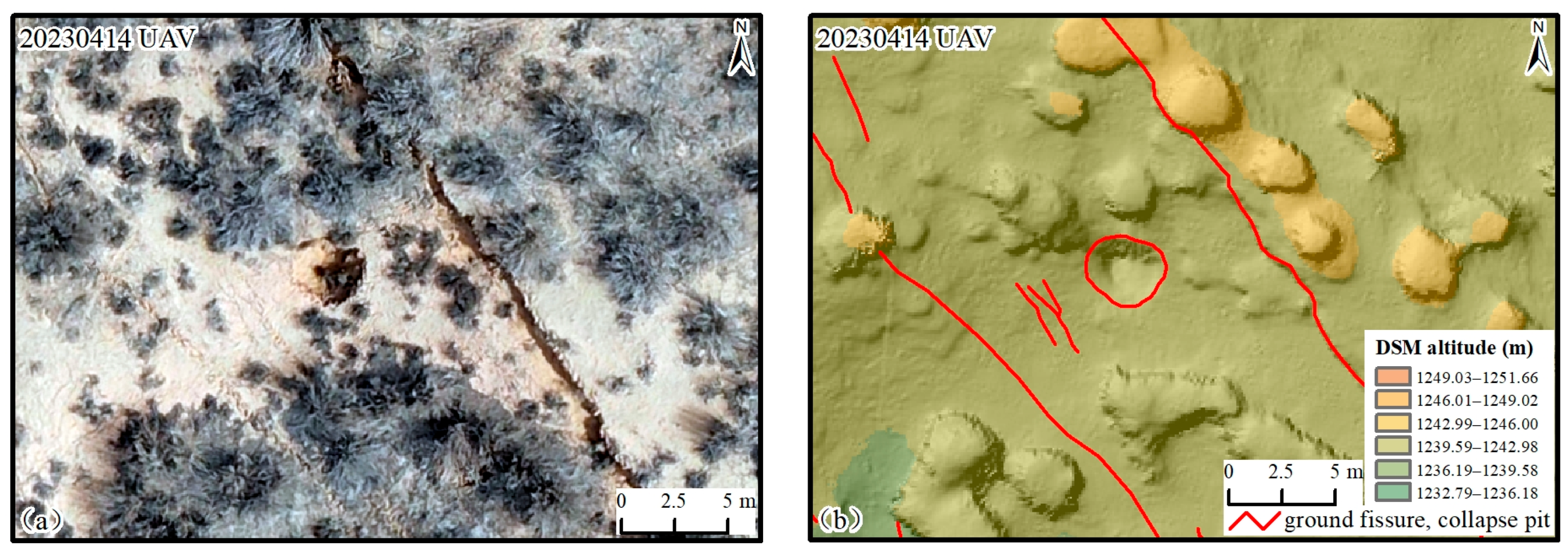
| Fissures in the thin roof strata basin | Unlike the typical forward “C” shaped distribution, it exhibits a reverse “C” shape. | The area with low-lying terrain and thin overburden layer, where the fissure belt develops to the surface fully, forming a local dominant subsidence center. | Straight and continuous, with occasional fault displacement of 0.2 to 0.6 m, width of 0.1 to 0.3 m, and occasional development of noticeable steps and collapse pits. |
Disclaimer/Publisher’s Note: The statements, opinions and data contained in all publications are solely those of the individual author(s) and contributor(s) and not of MDPI and/or the editor(s). MDPI and/or the editor(s) disclaim responsibility for any injury to people or property resulting from any ideas, methods, instructions or products referred to in the content. |
© 2024 by the authors. Licensee MDPI, Basel, Switzerland. This article is an open access article distributed under the terms and conditions of the Creative Commons Attribution (CC BY) license (https://creativecommons.org/licenses/by/4.0/).
Share and Cite
Tao, T.; Han, K.; Yao, X.; Chen, X.; Wu, Z.; Yao, C.; Tian, X.; Zhou, Z.; Ren, K. Identification of Ground Fissure Development in a Semi-Desert Aeolian Sand Area Induced from Coal Mining: Utilizing UAV Images and Deep Learning Techniques. Remote Sens. 2024, 16, 1046. https://doi.org/10.3390/rs16061046
Tao T, Han K, Yao X, Chen X, Wu Z, Yao C, Tian X, Zhou Z, Ren K. Identification of Ground Fissure Development in a Semi-Desert Aeolian Sand Area Induced from Coal Mining: Utilizing UAV Images and Deep Learning Techniques. Remote Sensing. 2024; 16(6):1046. https://doi.org/10.3390/rs16061046
Chicago/Turabian StyleTao, Tao, Keming Han, Xin Yao, Ximing Chen, Zuoqi Wu, Chuangchuang Yao, Xuwen Tian, Zhenkai Zhou, and Kaiyu Ren. 2024. "Identification of Ground Fissure Development in a Semi-Desert Aeolian Sand Area Induced from Coal Mining: Utilizing UAV Images and Deep Learning Techniques" Remote Sensing 16, no. 6: 1046. https://doi.org/10.3390/rs16061046