

A Modified Range Doppler Algorithm for High-Squint SAR Data Imaging

1
School of Electronics and Information Engineering, Beihang University, Beijing 100191, China
2
Beijing Institute of Remote Sensing Equipment, Beijing 100191, China
3
Shanghai Institute of Satellite Engineering, Shanghai 201100, China
*
Author to whom correspondence should be addressed.
Remote Sens. 2023, 15(17), 4200; https://doi.org/10.3390/rs15174200
Submission received: 3 July 2023
/
Revised: 24 August 2023
/
Accepted: 25 August 2023
/
Published: 26 August 2023
(This article belongs to the Special Issue Advanced Radar Signal Processing and Applications)
Abstract
:The high-squint airborne Synthetic Aperture Radar (SAR) has the ability to detect the target area flexibly, and the detection swath is significantly increased compared with the side-looking SAR system. Therefore, it is of great significance to carry out research on high-precision imaging methods for high-squint airborne SAR. However, the high-squint SAR echoes have large Range Cell Migration (RCM), resulting in severe range–azimuth coupling and strong spatial variation. In this paper, a Modified Range Doppler Algorithm (MRDA) is proposed to cope with these effects introduced by the significant RCM in high-squint airborne SAR imaging. The bulk compensation preprocessing is first adopted to remove the considerable RCM and severe cross-coupling in a two-dimensional frequency domain. Then, Non-Linear Chirp Scaling (NLCS) in the range direction is utilized to equalize the range-variant chirp rate caused by the residual RCM and coupling and, therefore, the consistent range phase compensation can be fulfilled in range frequency domain. The modified correlation processing is executed to compensate the residual Doppler phase modulation, the residual RCM and the range-variant cubic phase modulation, which guarantees the characteristics of high efficiency and high precision. The simulations have demonstrated that the MRDA can focus the SAR echoes with large squint angles more effectively than the algorithms based on the Linear Range Walk Correction (LRWC) method.
1. Introduction
As a typical active microwave remote sensing technology, different from optical satellite systems, Synthetic Aperture Radar (SAR) has all-day and all-weather working capabilities [1,2]. SAR is an imaging radar that can provide two-dimensional high-resolution images, which are widely used in various fields, such as environmental protection, resource exploration, disaster monitoring, battlefield environment reconnaissance, target precision attack, etc., and play an important role in many civil and military fields. Since the concept of SAR was first proposed by Carl Wiley of Goodyear Aircraft Corporation in the 1950s, this field has developed in the directions of high resolution, multi-mode, multi-polarization and multi-platform [3,4]. The traditional SAR system operates in broadside mode, which means the radar Line of Sight (LOS) is perpendicular to the platform’s flight path. When the system works in this mode, it can only observe and image the broadside area of the platform, and therefore flexible observation and information acquisition for complex environments cannot be achieved. Normally, the angle between the LOS direction and the vertical direction of the flight path is defined as the squint angle [2]. The large squint angle SAR platform allows the LOS direction to vary in a large scope, which can break through the above limitations and realize flexible multi-angle detection. Additionally, the SAR system with large squint angle can also acquire the multi-angle scattering characteristics of the target, so as to realize the precise identification of the key targets [2,5,6]. Therefore, high-squint airborne SAR has significant application value in many fields.
Due to the significant Range Cell Migration (RCM) and severe range–azimuth cross-coupling of high-squint SAR echoes, many existing image-processing algorithms cannot be applied to large squint angle and large scene cases [5,6,7,8,9]. How to realize RCM Correction (RCMC) and cross-coupling removal for high-squint airborne SAR is the premise of high-precision imaging. According to the implement domain of the algorithm, the existing imaging algorithms applied to the squint SAR system can be divided into two categories: time-domain and frequency-domain imaging algorithms. Theoretically, the time-domain imaging algorithm has the ability of high-resolution imaging and can be used in almost any mode and configuration of the SAR system. The typical time-domain imaging algorithm is represented by the Back Projection Algorithm (BPA) [10]. Although the BP algorithm has high precision and excellent adaptability, its computational complexity in the literature [10] is O(N3), which indicates its low computational efficiency. Aiming at the calculation efficiency problem of the BP algorithm, various improved algorithms have been proposed, as shown below. In [11], the Local BP Algorithm (LBPA) is proposed, and it reduces the complexity of the BP algorithm from O(N3) to O(N2.5). The Factorization Fast Back Projection Algorithm (FFBPA) is presented in [12], the complexity of which is O(N2log2N). As a classic BP-based efficient algorithm, it is widely used in practice. However, the efficiency improvements of the typical BP algorithm and its extended algorithms above are still rather limited in real-time imaging, especially in large-scale scene imaging.
The frequency-domain imaging algorithms can make full use of the “azimuth-invariant” property and improve the computational efficiency through batch processing. As the primary imaging algorithms at present, the significant RCM and severe coupling of the high-squint SAR echoes have hindered the application of the frequency-domain algorithms. Based on the classic Range Doppler Algorithm (RDA) in [13], an improved RD algorithm with Secondary Range Compression (SRC) operation [14] is proposed to realize SAR image-processing at small squint angles, which is not suitable for SAR imaging at large squint angles. A two-dimensional frequency algorithm, for example, the ωK Algorithm (ωKA), can accomplish squint SAR imaging under the condition of narrow imaging swath or poor resolution [15,16,17,18]. But when the squint angle further increases, the imaging algorithm is still incapable. This limitation is mainly attributed to the fact that the imaging parameters cannot be updated throughout the range cells. In addition, the Stolt interpolation required in the ωKA will have a great side effect on SAR imaging efficiency. The Polar Format Algorithm (PFA) is another effective approach to cope with the large squint angle SAR imaging problem. A PFA-based Two-Stage Focusing Algorithm (TSFA) combining coarse focusing and fine focusing procedures is proposed in [19] to correct the significant RCM and severe range–azimuth decoupling via a “squint minimization” operation. It should be noted that the PFA is generally used in the SAR spotlight mode, and the imaging results are obtained by polar coordinate projection and transformation, which require a large amount of calculation and therefore limit its application. Affected by the wavefront curvature, the traditional PFA cannot meet the imaging requirement of a large scene. Although the new PFA-based algorithm in [20] can expand the imaging size, the two-step PFA processing and the block processing bring a greater computational burden. As another frequency-domain algorithm, the Chirp Scaling Algorithm (CSA) [21,22] plays a key role in the research of squint SAR imaging algorithms. The “squint minimization” preprocessing is first proposed in [23] to realize the echo RCMC and cross-decoupling, after which operation the Azimuth Non-Linear Chirp Scaling (ANLCS) method is used to resolve the azimuth variation problem introduced by the preprocessing. In [24], an extended two-step focusing algorithm is proposed, which solves the two-dimensional spectrum distortion problem caused by the squint angles and removes the two-dimensional coupling by means of a “non-linear shift” method. The “squint minimization” and “non-linear shift” methods are collectively referred to as Linear Range Walk Correction (LRWC) in the literature [25]. An Extended Non-Linear Chirp Scaling Algorithm (ENLCSA) is given to equalize the azimuth-variant frequency modulation rate and the higher-order terms are also considered in [25]. Essentially, the aforementioned LRWC-based algorithms result in range cell shifts for azimuthal non-central targets while eliminating the significant RCM and severe cross-coupling, which destroys the “azimuth-invariant” property. Since this azimuth variation caused by the ANLCS processing cannot be completely removed, the azimuth swath will be significantly reduced. Therefore, the LRWC-based algorithms in [19,23,24,25] cannot adapt to large scene imaging processing, especially for large squint angles cases.
In this paper, a Modified Range Doppler Algorithm (MRDA) is proposed for the high-squint airborne SAR system. In order to eliminate the significant RCM and severe range–azimuth cross-coupling of high-squint SAR echoes, this novel algorithm begins with bulk compensation preprocessing, which is performed in the two-dimensional frequency domain. Unlike the LRWC method in [19,23,24,25], the bulk compensation preprocessing does not introduce range cell shifts for the echo signals, and thus the “azimuth-invariant” property can be preserved, which means the batch focusing processing can be accomplished in the azimuth frequency domain. After the bulk compensation preprocessing, only the residual RCM and the residual cross-coupling can be observed in the echo signals. The Non-Linear Chirp Scaling (NLCS) method is then adopted to equalize the range-variant frequency modulation rate of the range pulses caused by the residual cross-coupling. The consistent range compression can subsequently be realized by the range phase compensation function in range frequency domain. The modified correlation processing is then be applied to precisely remove the residual RCM, the residual Doppler phase modulation and the range-variant cubic phase modulation introduced by the residual cross-coupling. The characteristics of the modified correlation reference function can be summarized as follows: firstly, as the bulk RCM has been corrected by the bulk compensation preprocessing and the variation of the quadratic range frequency term has been eliminated by the NLCS method, the correlation window length is significantly shortened, which ensures processing efficiency. Secondly, the construction of the reference function takes into account the range-variant cubic phase modulation introduced by the residual cross-coupling. Therefore, the modified correlation processing can correct the asymmetry of the range side-lobes while completing the residual RCMC and the residual Doppler phase compensation, which can realize high-precision processing. Ultimately, the final focused SAR image data can be obtained via an Azimuth Inverse Fast Fourier Transform (AIFFT) operation. The feasibility of the proposed MRDA is then verified by comparative simulations.
The rest of this paper is organized as follows: the geometry and signal models are displayed in Section 2. The details of the proposed MRDA for a high-squint airborne SAR system are shown in Section 3. The simulations and results are given in Section 4. A further discussion and conclusion are present in Section 5 and Section 6, respectively.
2. Geometry and Signal Models
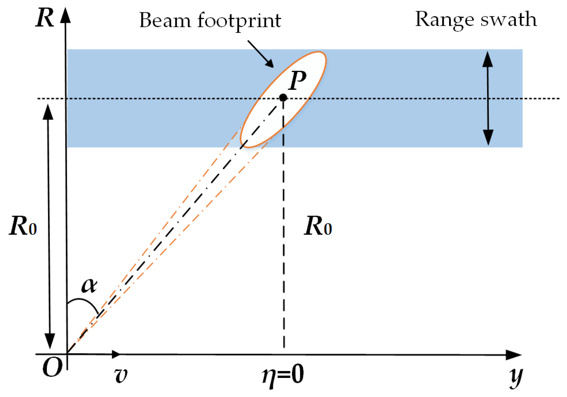
The geometry model is provided in Figure 1 for the high-squint airborne SAR system. The platform flies along the y-axis with a fixed velocity v. In this paper, the squint angle α is defined as the complementary angle between the line-of-sight direction and the flight path of the platform. Point P is an arbitrary target in the scene. R0 is the closest slant range between the sensor and the point target P, and η = 0 represents the corresponding azimuth time when the sensor passes the closest slant range R0. The range history R(η) of point target P can then be expressed as
The baseband signal for a single point target after demodulation has the following complex form:
where τ and η are the range fast time and azimuth slow time, respectively. wa(∙) and wr(∙) are the antenna patterns in azimuth and range directions, respectively. ηc represents the beam center-crossing time in the azimuth direction, λ is the wavelength of the transmitted signal, c is the speed of light in space, kr is the range frequency modulation rate of the transmitted range pulse, R(η) is the instant slant range in different azimuth times as denoted in the range of Equation (1).
Using the Principle of Stationary Phase (POSP) with Equation (2), we can obtain
where fτ and fη represent the frequencies in range and azimuth directions, respectively. fηc is the Doppler centroid frequency for a certain point target, and f0 is the carrier frequency of the transmitted signal. Wa(∙) and Wr(∙) are the envelopes of the signal spectrum in azimuth and range directions, respectively. D2df is the cosine value of the instantaneous squint angle at the azimuth time η in the straight-line geometry shown in Figure 1 and is also considered as the migration factor in the two-dimensional frequency domain. The specific expression of D2df is
3. Modified Range Doppler Algorithm
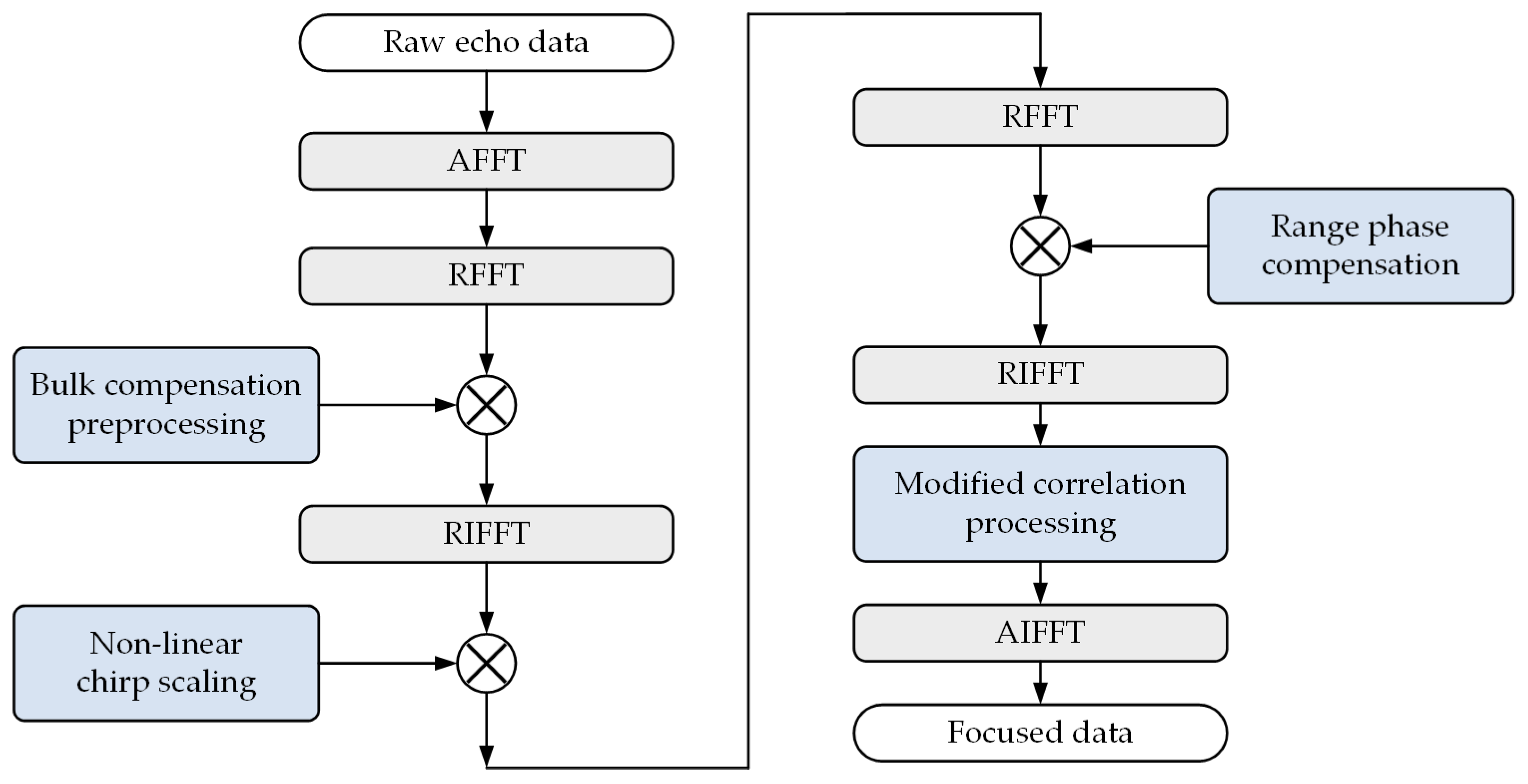
Based on the geometry and signal models shown in Section 2, the MRDA is proposed in Section 3 for a high-squint airborne SAR system. The block diagram of the proposed MRDA is shown in Figure 2 below. Firstly, the raw echo data are transformed into the two-dimensional frequency domain, and the bulk compensation preprocessing is applied to remove the range–azimuth cross-coupling and the total RCM of the reference range cell without introducing the azimuth-variation effect. Then, the NLCS processing is performed along the range direction in the Range Doppler (RD) domain to equalize the range-variant frequency modulation rate introduced by the residual cross-coupling. Subsequently, the range matched filter can be realized via the uniform range phase compensation, and the compressed range pulses can therefore be obtained. Finally, the modified correlation processing in the RD domain is adopted to accomplish the residual RCMC, the residual Doppler phase modulation compensation and the range-variant cubic phase modulation compensation, and the focused SAR data can be acquired at the end via an AIFFT operation.
3.1. Bulk Compensation Preprocessing
In order to remove the range–azimuth coupling, the bulk compensation filter is constructed in the two-dimensional frequency domain and is given the form of
where Rref is the referent closest slant range in the central range gate. By multiplying Equation (3) with (5), the signal after bulk compensation preprocessing in the two-dimensional frequency domain can be written as
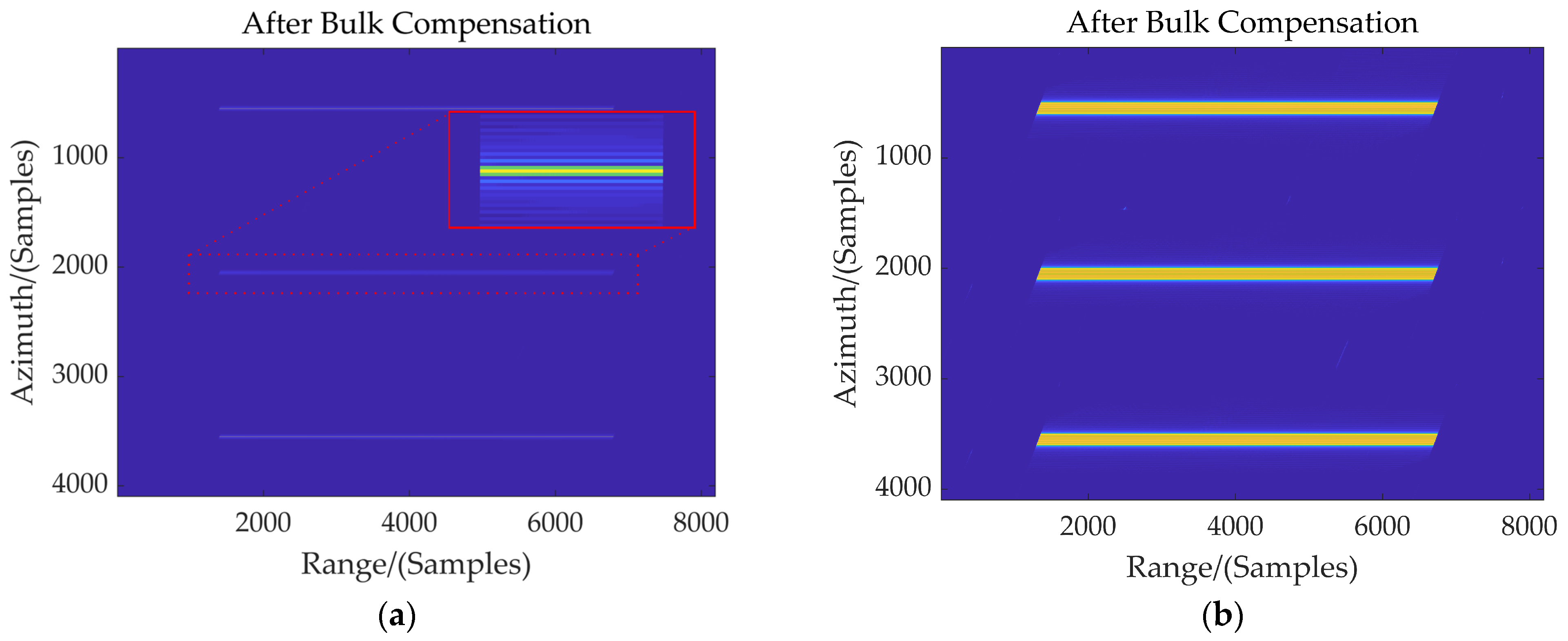
A simulation using the parameters listed in Table 1 is conducted to explain the effect of the bulk compensation preprocessing. Figure 3a,b depict the raw echo signals in the two-dimensional time domain after bulk compensation for central and non-central range cells, respectively. Three point targets are positioned at the same range gate with a constant azimuth interval of 1 km. The range position displacement is set to be 3 km for these three point targets, shown in Figure 3b. After bulk compensation preprocessing, the total RCM, Doppler phase and the range–azimuth coupling for the target positioned at the central range cell are removed as is shown in Figure 3a. The signal for the central point target has been zoomed into, shown by the red solid line box. However, the slight skew of the signal along the horizontal direction and the extension along the vertical direction indicate that there are still residual RCM and residual Doppler phase modulation, respectively, for targets located in non-central range cells. Moreover, this extension can also account for the residual cross-coupling. Therefore, it can be concluded from the above simulation results that the bulk compensation preprocessing can eliminate the total RCM of the reference range cell while maintaining the “azimuth-invariant” property and realize the range–azimuth decoupling processing.
3.2. Non-Linear Chirp Scaling
Using Taylor expansion and keeping Equation (7) to the third order, we can obtain
where Df is the range cell migration factor in the RD domain, which represents the cosine value of the instantaneous squint angle corresponding to different azimuth positions of a certain range gate.
After applying Taylor expansion to Equation (7), the uniformly compensated echo signal is further transformed into the RD domain using the POSP:
Neglecting the cubic term of fτ in Equation (8), the stationary phase point can be obtained by the following equation:
where Rres is the relative closest range and can be defined as
When Equation (14) is set to be zero, the range frequency fτ and fast time τ can be related by
The RD spectrum after bulk compensation preprocessing can be given as
where the range antenna pattern wr(·) reveals the residual RCM of the echo signal. The magnitude and phase of the azimuth signal are represented by the second and third terms in Equation (18), respectively. The fourth term and the fifth term successively represent the quadratic and cubic range frequency modulation terms of the range signal. It can be determined from the above analysis that the updated range frequency modulation rate and the residual RCM are both variant in the range dimensional. Since Equation (18) satisfies the condition of |krz1| << 1, the following approximation can be obtained:
According to Equation (20) above, km1 is the range-variant part of the updated range frequency modulation rate km, which is related to both the azimuth frequency fη and the relative closest range Rres. Actually, the variation of km1 with Rres is the dominant term, so the variation of km1 along the azimuth is ignored. The Non-Linear Chirp Scaling (NLCS) filter is then given a cubic form of fast time τ in the range direction to remove the range-variant component of range frequency modulation rate km.
where
The influence of the range-variant linear term introduced by the NLCS operation on the matched filter will be taken into account in the modified correlation processing. The quadratic term is useful for eliminating the variation of km in the range direction. It should be noted that the cubic term introduced by the NLCS operation is uniform for different range cells and can be compensated consistently by the range matched filtering.
After utilizing the NLCS operation, the echo signal in Equation (18) is changed into
So far, the compression processing in the range direction can be completed by the batching processing in the range frequency domain.
3.3. Range Phase Compensation
In order to realize range compression, the signal in Equation (24) is then transformed into the two-dimensional frequency domain by Range FFT (RFFT):
where the second exponential term is the consistent quadratic range frequency modulation phase. The third and fourth exponential terms represent the range-variant cubic frequency modulation phase and the residual RCM, respectively, the compensation of which can be realized via the followed modified correlation processing. Therefore, the expression of the range compression filter is
Additionally, the cubic phase introduced by the NLCS filter also should be taken into consideration, and this cubic phase compensation function is given the form of
where τ(fτ) is the stationary phase point of RFFT and can be expressed as
The range phase compensation filter can therefore be integrated as
The two-dimensional frequency signal after range phase compensation via Equation (29) becomes
The three exponential terms in the above Equation (30) represent the range-variant azimuth phase modulation, cubic phase modulation of range frequency and residual RCM, respectively.
3.4. Modified Correlation Processing
After the Range Inverse FFT (RIFFT) is applied to Equation (30), the signal is again transformed into the RD domain:
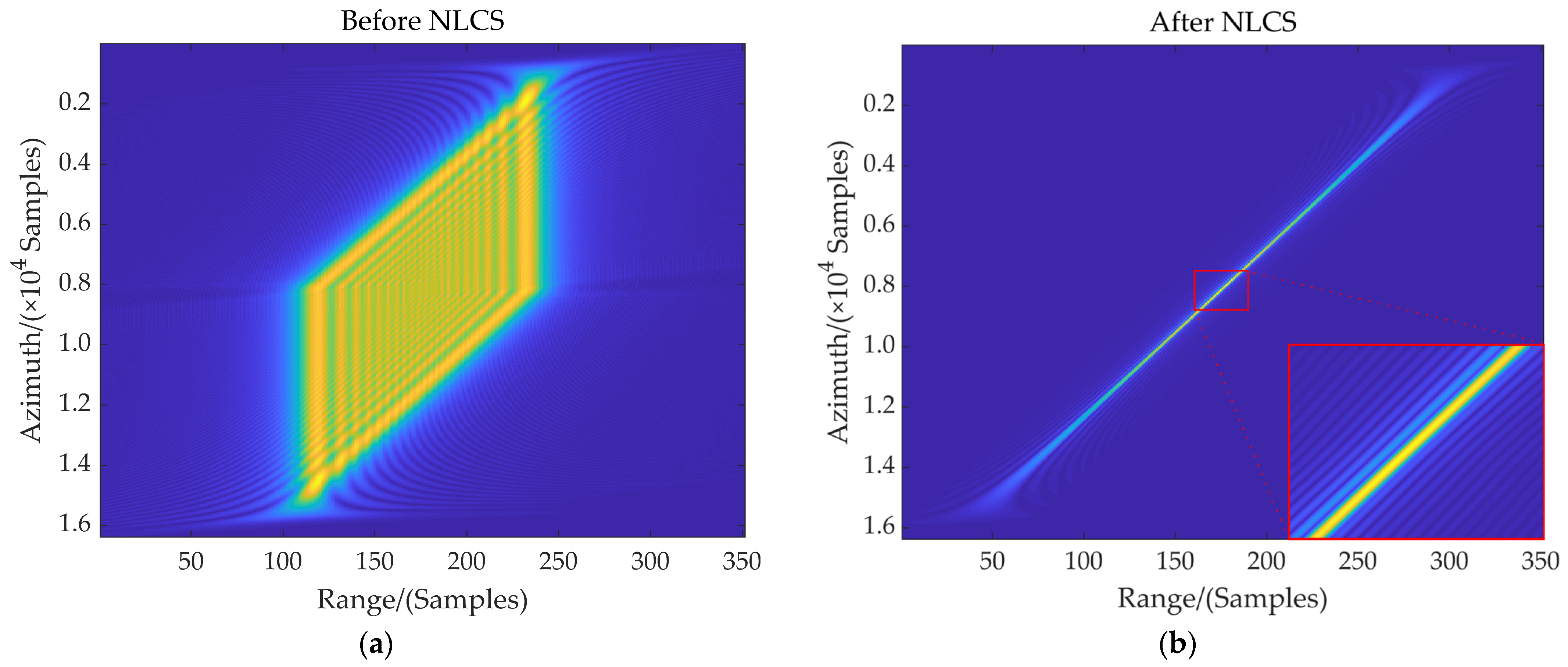
where r−1(∙) denotes the RIFFT operation. Figure 4a shows the range compressed result before NLCS processing in the range direction, which reflects the range pulse broadening due to the residual cross-coupling for the range marginal target. It can be observed from Section 3.2 that the variation of the range frequency modulation rate caused by the residual cross-coupling has been eliminated, which allows the signal to be consistently compressed by the range phase compensation in Section 3.3. The range compressed result after NLCS processing is depicted in Figure 4b, and the width of the range signal in the fast time domain is significantly reduced, which indicates that the window width of the correlation processing will be remarkably shortened for large squint angle cases. Additionally, Equation (32) shows that there is an additional range-variant cubic phase modulation of the rectangular window function in the range direction, which is also introduced by the residual cross-coupling. Different from the normal sinc function, the compressed range pulse r(τ, fη; R0) therefore has an asymmetric form as is shown in the partially enlarged view of Figure 4b, where obvious side-lobe energy asymmetry appears. This is the key point to distinguish the modified correlation processing from the traditional ones.
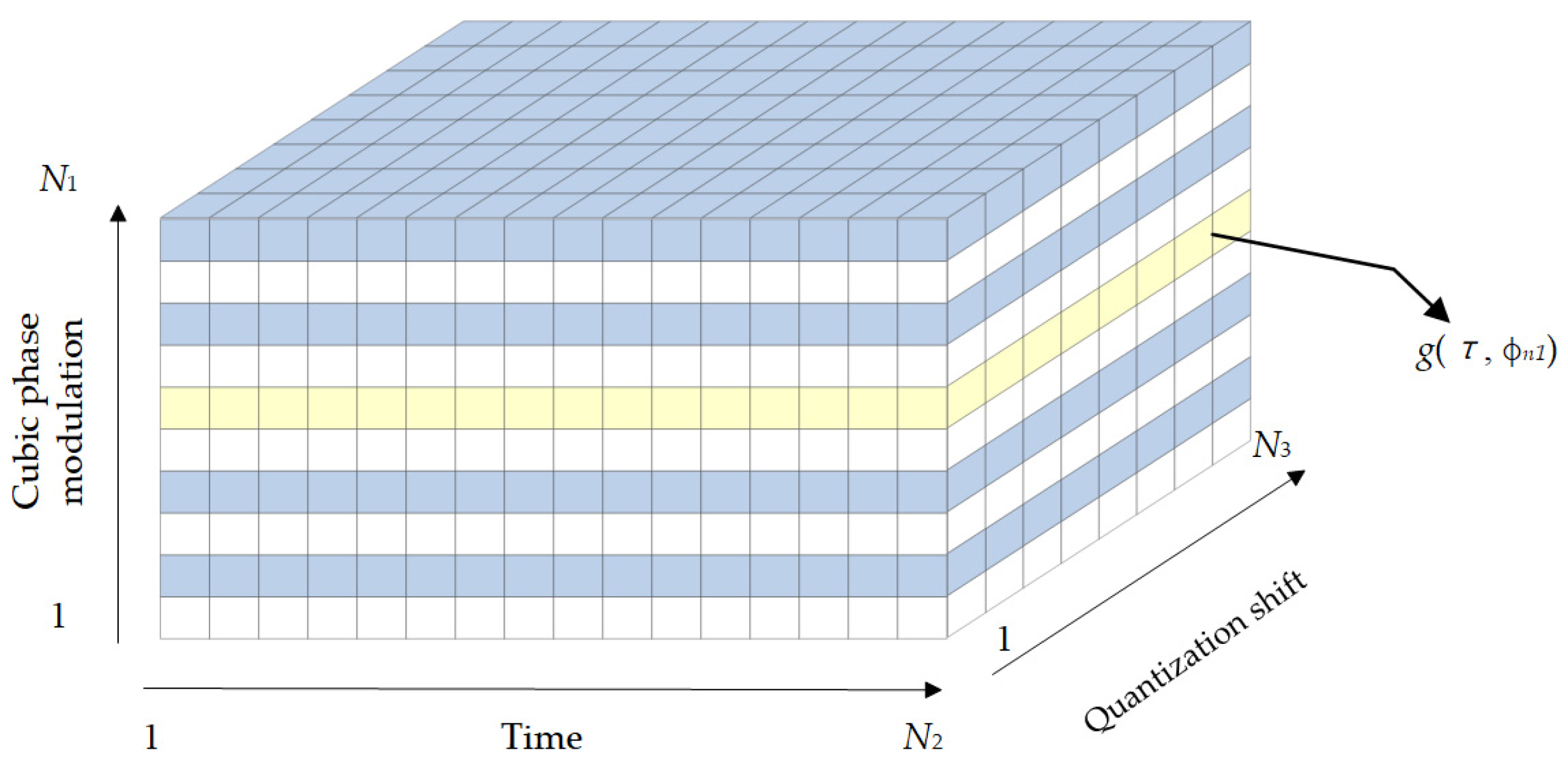
To compensate the range-variant cubic phase modulation in Equation (32), we first quantify the maximum value of this cubic phase at different azimuth frequencies for different range cells. Assuming that the cubic phase modulation quantization scope is [−φ, φ], the quantization interval is 2φ/(N1 − 1) when the corresponding quantization point is N1, which is shown in the height dimensional in Figure 5. For the n1th quantization interval, the corresponding cubic phase modulation ϕn1 is
The compressed range pulse with phase modulation ϕn1 can be expressed as
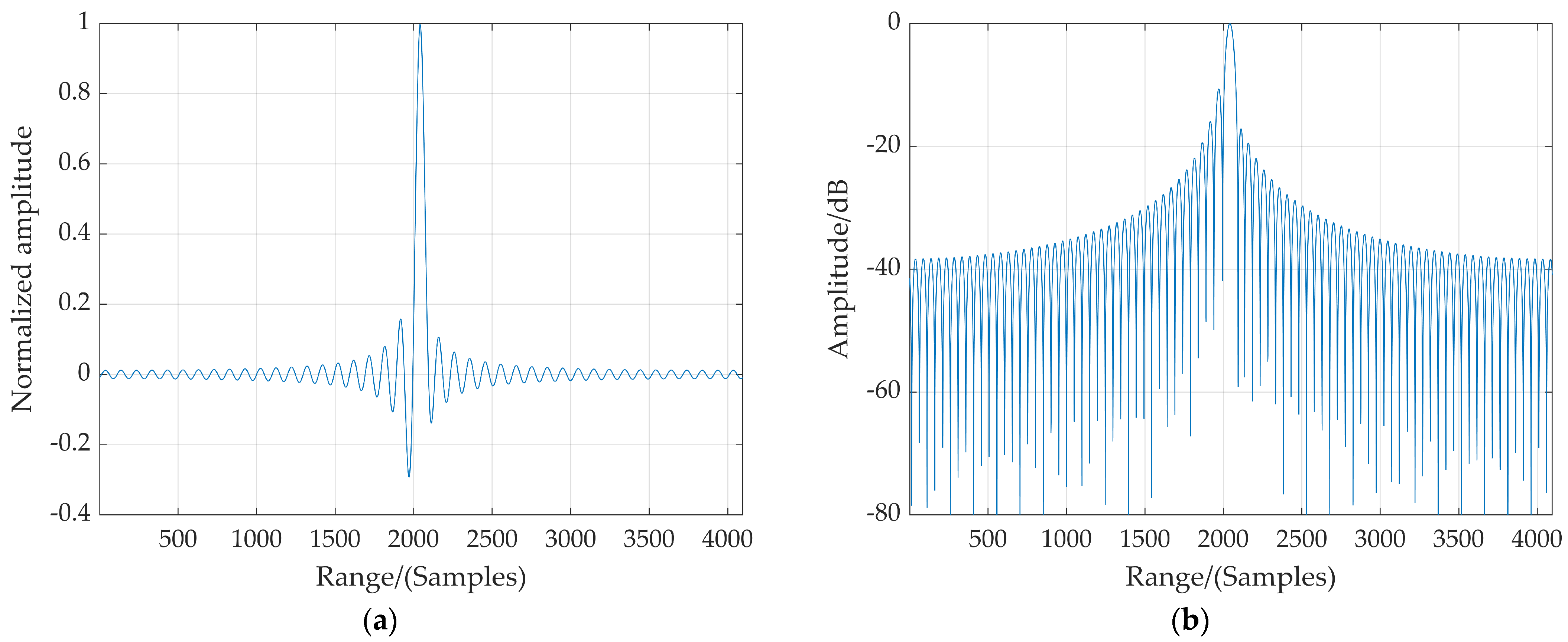
where n1 = 1, …, N1. Figure 5a,b show the compressed range pulse g(τ, ϕn1) with normalized amplitude and dB-scaled normalized amplitude when phase modulation ϕn1 = π/4, respectively. Kernel functions with quantization shifts can be obtained by quantizing g(τ, ϕn1) at equal intervals, and thus a two-dimensional matrix of kernel function is constructed as is indicated by the yellow boxes in Figure 6. N2 and N3 denote the length of the correlation window and the number of quantization shifts for RCMC, respectively. The above analyses illustrate that the kernel function under different cubic phase modulations in the modified correlation processing is a three-dimensional matrix, which can compensate the range-variant cubic phase modulation while completing the residual RCMC.
The modified correlation reference function can then be given as
In order to achieve accurate focusing of non-central range cells in high-squint observation, the modified correlation processing is adopted, which can be described as
where
τ0 and τ′0 are the residual range-variant RCM after bulk compensation preprocessing and after NLCS processing, respectively. The second term in Equation (38) is the extra RCM introduced by the range-variant linear term of the NLCS operation in Section 3.2.
Through the modified correlation processing, the residual RCM, the residual Doppler phase modulation and the range-variant cubic phase modulation introduced by the residual cross-coupling are removed, and the focused SAR image can finally be obtained by
where a−1(∙) represents the AIFFT operation and p(∙) denotes the sinc function. According to Equations (37) and (38), τc can be expressed as
Different from simulated examples, the actual system is affected by various noises. The impact of the Signal-to-Noise Ratio (SNR) on the algorithm is mainly reflected in the estimation of Doppler parameters in real data processing, which limits the estimation accuracy of Doppler parameters. In order to fulfill precise focusing processing, especially in practical real-time imaging systems, it is necessary to ensure the accuracy and efficiency of Doppler parameter estimation.
4. Simulations and Results
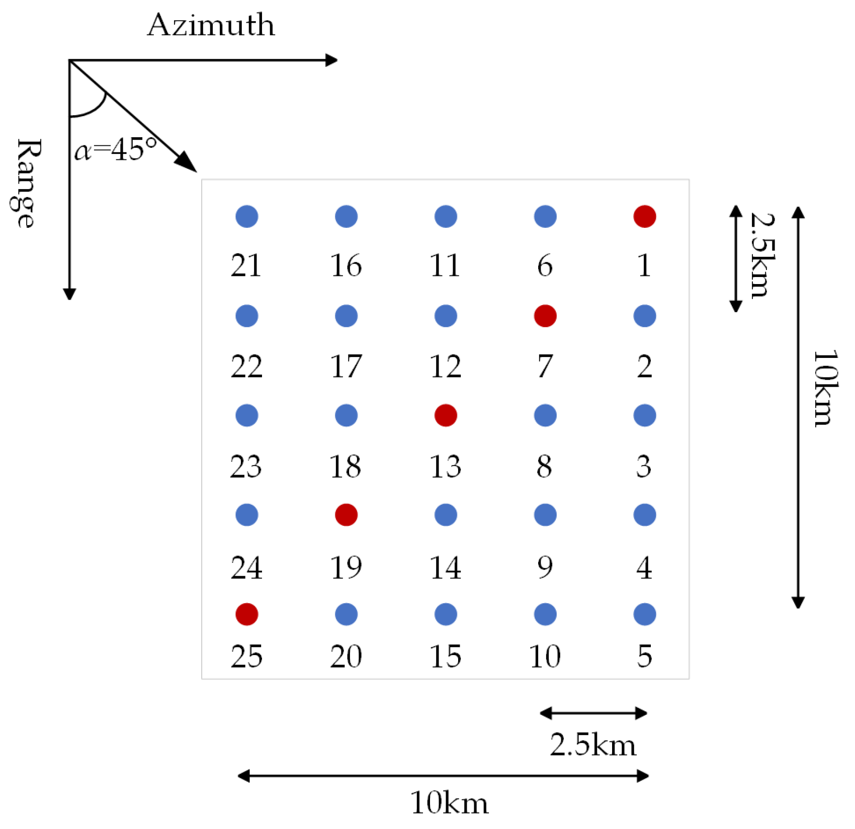
In order to validate the feasibility of the proposed MRDA for the high-squint airborne SAR imaging, point target simulations are carried out in this section employing the parameters listed in Table 1. As depicted in Figure 7, a 5 × 5 point matrix is evenly arranged in a square area of 10 km × 10 km in the ground scene, and the distance interval is 2.5 km both in range and azimuth directions. The squint angle α is set to be 45°. Rectangular antenna patterns are assumed in both these two directions.
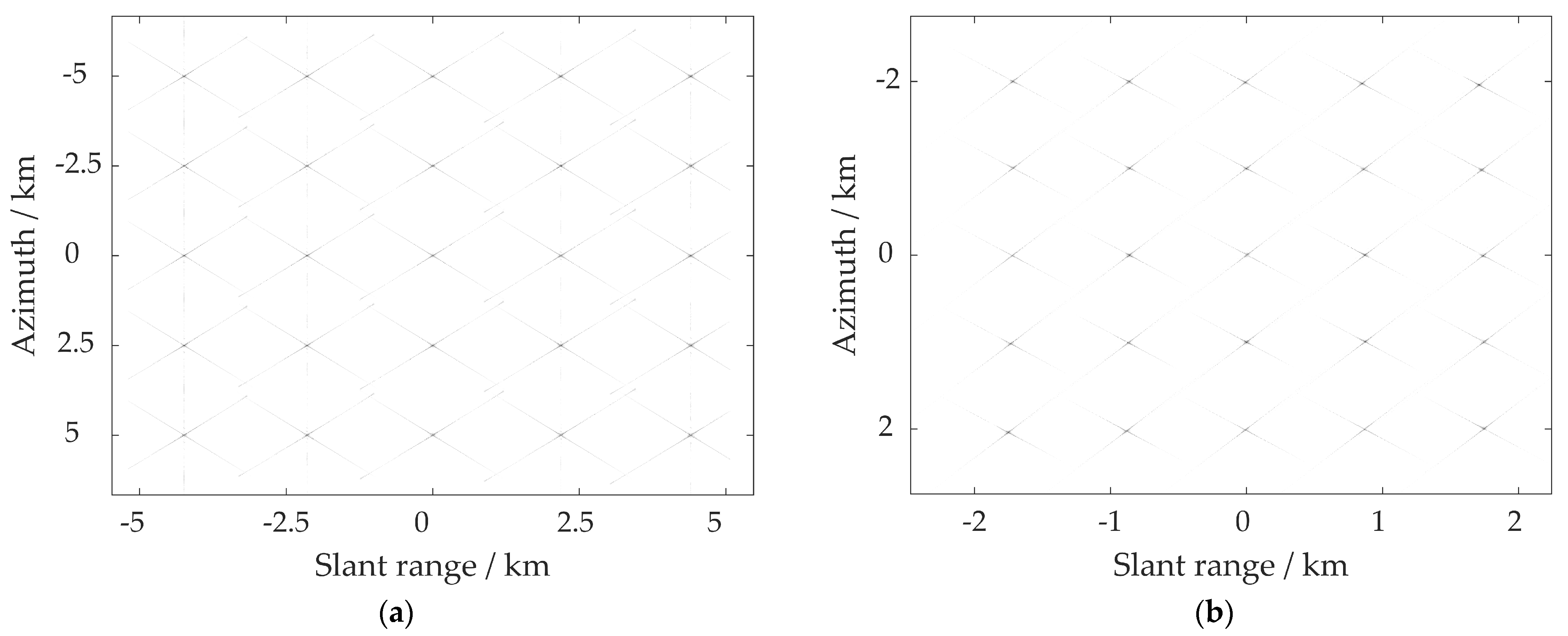
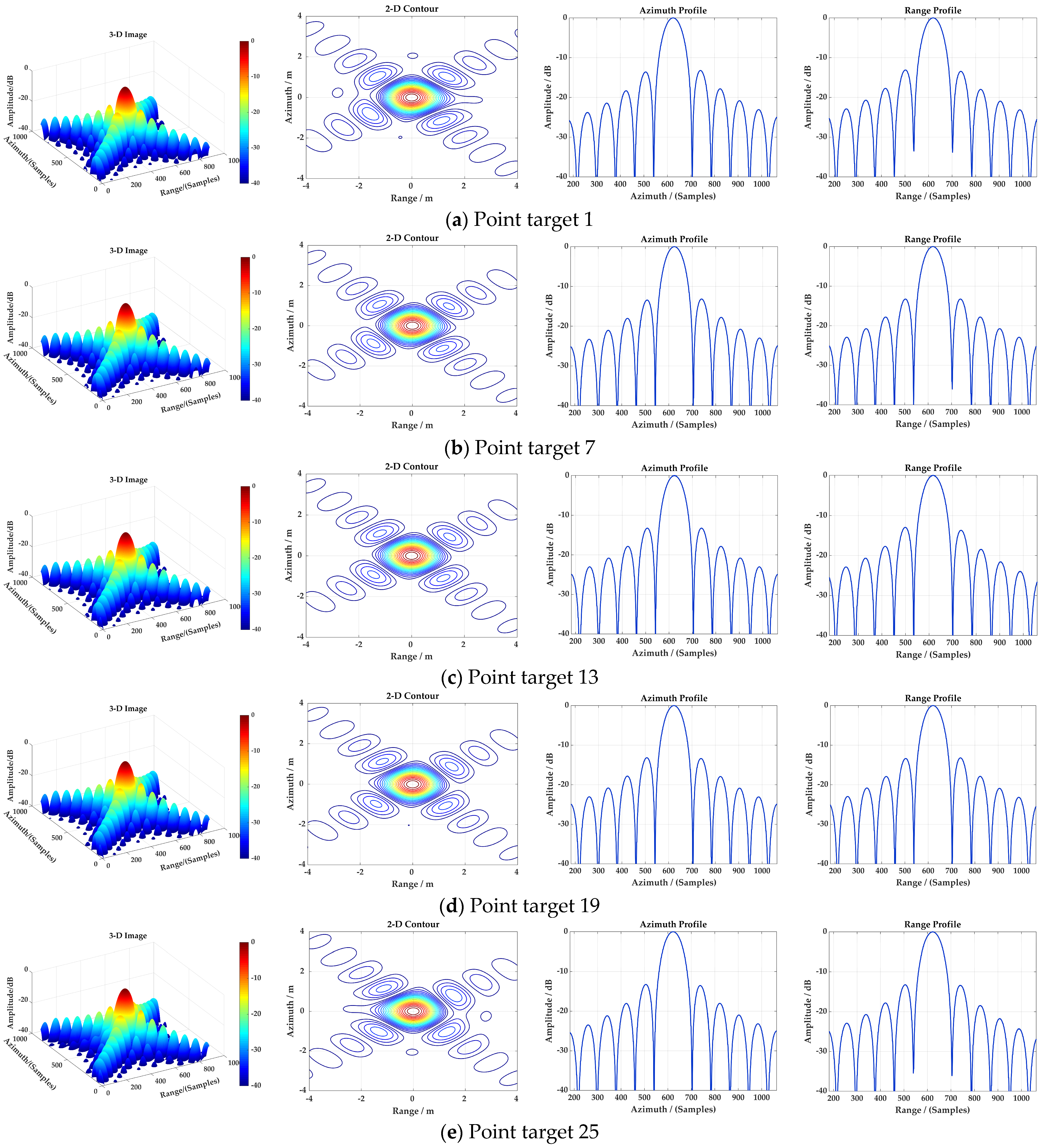
The simulation results adopting the proposed MRDA are displayed in Figure 8a and Figure 9. The focused SAR image of the point matrix is shown in Figure 8a, and the slant range plane has not been projected onto the ground range plane. The target energy is displayed at the dB scale to facilitate the identification of each point target. The imaging results (two-dimensional contours, azimuth profiles and the range profiles) of the chosen point targets 1, 7, 13, 19 and 25 are shown in Figure 10a–e, respectively. For the point targets 7 and 19 positioned at 2.5 km away from the scene center, the imaging performance is quite good, and it is almost consistent with that of central point target 13 as can be seen in Figure 10b,d. From Figure 10a,e, however, slight distortion can be observed in the two-dimensional contour and range profile of the marginal point target 5 km away from the scene center. The following reasons lead to this distortion in the range dimensional. On the one hand, the variation of range frequency modulation rate km1 along the azimuth frequency is ignored during the NLCS processing. The bulk compensation preprocessing eliminates the major range–azimuth cross-coupling of the signal in non-central range cells, but the residual cross-coupling still exists, which will result in spatial variation of the range frequency modulation rate km1. Actually, km1 is not only related to the relative closest slant range Rres but also to the azimuth frequency fη. However, km1 is considered to be weakly correlated with fη. On the other hand, additional terms introduced by the NLCS operations also cause slight degradation. While equalizing the comprehensive range frequency modulation rate km, the NLCS processing brings about a range-variant linear term and identical quadratic term of range frequency fτ, which can be compensated in the subsequent processing. The range position displacement caused by the linear term will lead to incomplete equalization, which means the existence of small residual range variation of km. To illustrate the performance of this imaging algorithm from a quantitative perspective, the evaluation indicators of the chosen point targets are given in Table 2, including the evaluation resolution, the Peak Side-Lobe Ratio (PSLR) and the Integrated Side-Lobe Ratio (ISLR) of profiles both in range and azimuth dimensions. When the simulation parameters listed in Table 1 are employed and the squint angle α is set to be 0°, the theoretical values of the slant range resolution and azimuth resolution are both 0.89 m. When the rectangle patterns are assumed both in range and azimuth directions, the theoretical values of the PSLR and the ISLR are −13.26 dB and −9.68 dB, respectively. It can be seen from Table 2 that all these point targets are well focused in the azimuth direction within the whole scene arranged in Figure 7—the azimuth PSLR deviates from the ideal value of −13.26 dB by less than 0.09 dB. Slight distortion occurs for the range profiles of the chosen point targets—the range PSLR has a degradation of less than 0.3 dB from the expected value. Overall, all chosen point targets are well focused and show great consistency, which verifies the effectiveness of the proposed MRDA.
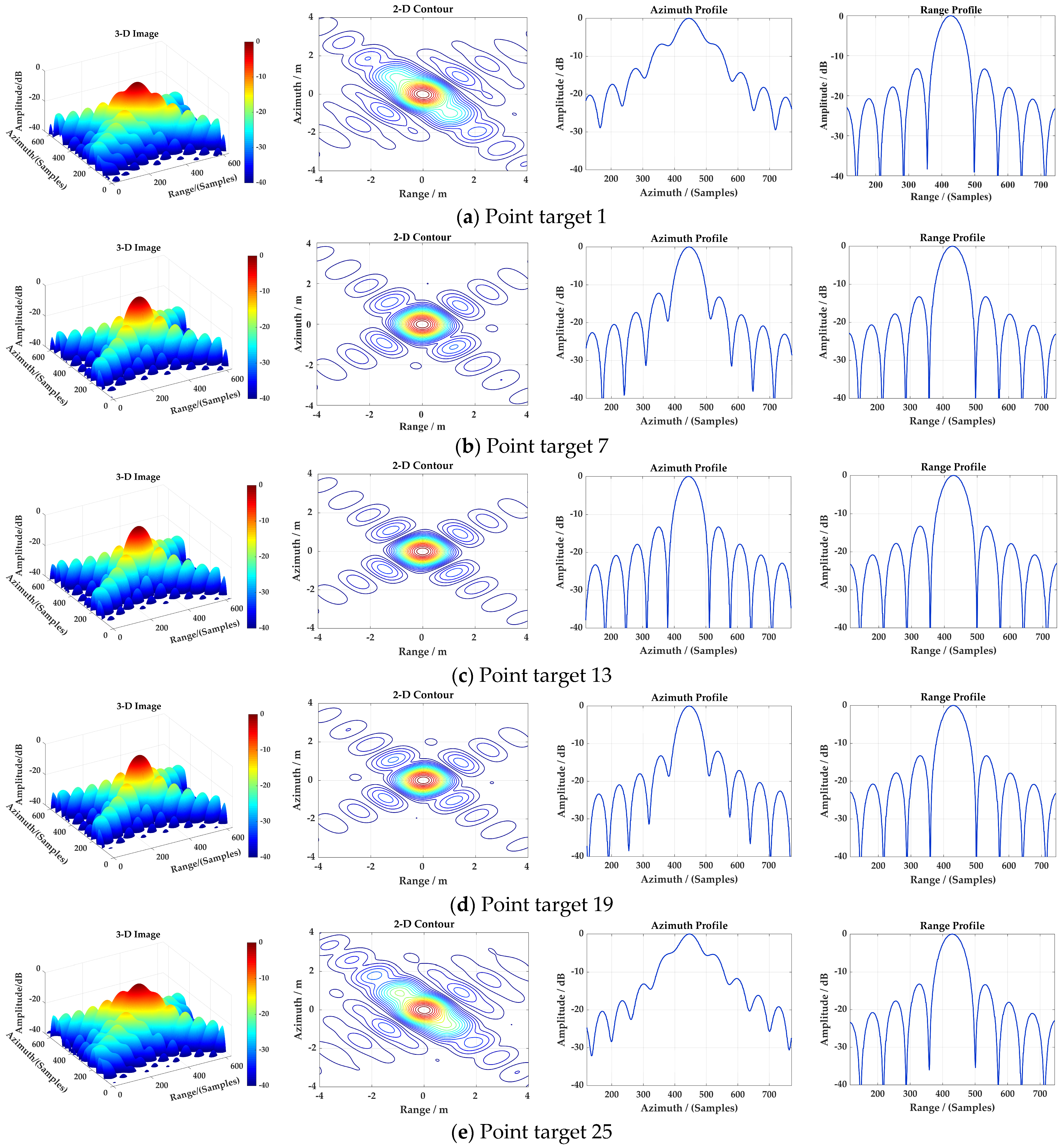
By using the LRWC-based algorithm, another point target simulation is carried out to compare the performance of the proposed MRDA. The simulation parameter configuration is the same as that of the MRDA as shown in Table 1, whereas the scene parameter configuration is different, which is reflected in the fact that the point matrix intervals both in range and azimuth directions are 1 km. Therefore, the size of the imaging scene is set to be a square area of 4 km × 4 km in this comparison experiment. The imaging result of the point matrix when the LRWC-based algorithm is adopted is depicted in Figure 8b and the details of the imaging performances for the selected point targets are shown in Figure 10. It is worth noting that the focused SAR image in Figure 8b has been subjected to geometric correction processing, so the geometric distortion caused by the LRWC operation has been removed. Significant degradation can be observed from the two-dimensional contours and the azimuth profiles of point targets 1 and 25 shown in Figure 10. The azimuth phase error has even reached 3/4π, which far exceeds the phase error standard of 1/4π. Significant main-lobe extensions and side-lobe elevations can be seen in Figure 10a,e. In order to describe the degree of distortion caused by the LRWC-based method from a quantitative point of view, Table 3 presents the evaluation indicators of the selected point targets. Only the central point target 13 is well focused in the azimuth direction, and no deterioration occurs in azimuth evaluation indicators. Point targets 1 and 25 are the farthest from the center of the scene and hence suffer the severest quality degradation. From the analysis of azimuth resolution, Table 3 shows that the Impulse Response Widths (IRWs) in the azimuth direction of point targets 1 and 25 are 20% and 17% worse than that of the scene center point target 13, respectively, which indicates a clear deterioration in azimuth resolution. The PSLR and ISLR degradations in the azimuth direction for point targets 1 and 25 are approximately 7–8 dB and 5–6 dB, respectively. For the point targets whose displacements in azimuth and range directions are both 1 km, the azimuth PSLR degradation in the azimuth direction is more than 1.05 dB from the theoretical value. Practically, the above distortions are attributed to complicated azimuth variation introduced by the LRWC operation. For point targets located at different azimuth positions of the same range gate, different range cell shifts occur, which leads to the failure of the “azimuth-invariant” property. Since severe spatial variation of Doppler parameters along the azimuth direction, the frequency-domain algorithm can only guarantee target focus within a small azimuth swath. As shown in the simulation results shown in Figure 10 and Table 3, this azimuth variation cannot be completely eliminated even when employing the azimuth NLCS processing after the LRWC operation. By comparison with the proposed MRDA, the MRDA shows obvious superiority in focusing performance.
5. Discussion
5.1. Phase Error Analysis
From the analyses in Section 3.2, it can be seen that km1 has a weak correlation with azimuth frequency fη. Therefore, a very small integrated quadratic modulation term of range frequency remains after the NLCS operation in the range direction. For the range edge point targets, the maximum phase mismatch of a single range pulse at a certain azimuth time can be given by
where τp is the range pulse width and Δkr is the offset of the range chirp rate related to the azimuth frequency fη, which can be calculated by
where |·| represents the absolute value of an element. The integrated quadratic frequency modulation term resulting from the above NLCS processing is very small, which can be confirmed by the range profiles of point targets 1 and 25 in Figure 9.
5.2. Ground Range Error Analysis
In order to investigate the impact of the proposed algorithm on slant range geometry projection, the following analysis is conducted. The shortest slant range of a focused target in the ground scene is
where Δτ represents range time delay of the focused target relative to the central range cell. When the focused target is projected to the ground range plane, the corresponding range displacement relative to the scene center is
where β and β0 are look angles for central range cells and non-central range cells, respectively. Using the simulation parameters in Table 1, the relative range displacements for point targets 1 and 25 shown in Figure 9 can be obtained as −4999.46 m and 5000.32 m, respectively, and the corresponding ground range projection errors are 0.54 m and 0.32 m, respectively. Essentially, these projection errors are caused by the additional small linear phase modulation introduced by the NLCS operation in Section 3.2.
5.3. Computational Complexity Analysis
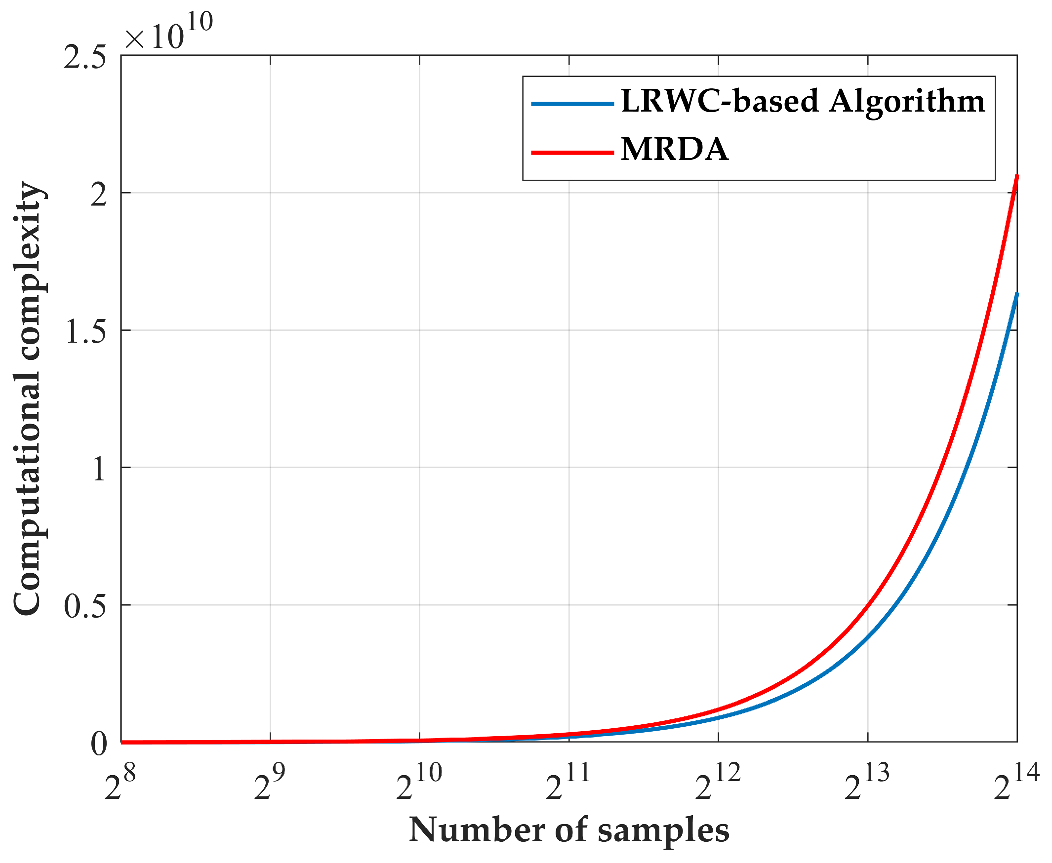
The computational complexities of the proposed MRDA and the referenced LRWC-based algorithm are also discussed in this section and are summarized in Table 4 and Figure 11. Range and azimuth sampling points are denoted by Nr and Na, respectively. The modified correlation window length in the range direction is represented by Nk, which is set to be 32 in the above simulation. Assuming the sampling points in range and azimuth directions are the same, i.e., Nr = Na = N, and set to be 214, the calculation complexities (Ci, i = 1, 2) in Table 4 are 1.64 × 10¹⁰ and 2.07 × 10¹⁰, respectively. The ratio of the computational complexities between the proposed MRDA and the LRWC-based algorithm can be calculated as
Equation (45) implies that the computational complexity of the proposed MRDA is increased by 26% compared to the LRWC-based algorithm using the simulation parameters listed in Table 1. For larger squint angles and better resolutions, the length of this correlation window will increase, which will further lead to a certain degree of decrease in the efficiency of the proposed algorithm.
5.4. Motion Error Compensation
The airborne SAR platform is easily affected by external factors such as airflow and weather in practical applications, which makes the actual motion of the SAR platform deviate from the ideal trajectory, resulting in unknown motion errors. Due to the impact of motion errors on imaging quality, SAR motion compensation also needs to be considered. Motion compensation based on echo data is the key step to achieve accurate imaging of the target area. There are two main approaches for motion compensation: parameter estimation and autofocus processing. In terms of parameter estimation, the research focuses on the estimation of Doppler centroid frequency and Doppler frequency modulation rate. The estimation methods of the former mainly include the energy equalization method, clutter locking method, radon transform method radon-transform-based method and its improved form [26,27,28,29]. The latter is represented by the map-drift method [30]. Phase Gradient Autofocus (PGA) is a classic autofocus method, which can realize high-order motion error compensation directly by estimating high-order phase errors [31]. The modified PGA based on the Weighted Maximum Likelihood (WML) can significantly improve convergence speed and promote the processing efficiency [32]. Accurate imaging of the target area can then be achieved by embedding the motion compensation into the imaging algorithms.
6. Conclusions
In this paper, a Modified Range Doppler Algorithm (MRDA) is proposed for a high-squint airborne SAR system, which can realize high-precision SAR echo imaging. The bulk compensation preprocessing is used to remove the significant RCM and severe range–azimuth cross-coupling of SAR echoes with large squint angles, which can simultaneously maintain the “azimuth-invariant” property. To equalize the range chirp rate, the range NLCS method is introduced in the imaging processing, after which the consistent range compression can be fulfilled by the range phase compensation operation in the range frequency domain. The modified correlation processing is performed in the RD domain to eliminate the residual range-variant RCM, the residual Doppler phase modulation and the range-variant cubic phase modulation introduced by the residual cross-coupling. The final focused high-squint airborne SAR image can be obtained via an AIFFT operation. Simulations are conducted in this paper to verify the effectiveness of the proposed MRDA. Evaluation results of the proposed MRDA show better performance than that of the LRWC-based algorithm for a high-squint airborne SAR system.
Author Contributions
Conceptualization, P.W. and J.C.; methodology, P.W. and Y.G.; software, Y.G.; validation, Y.G., X.Z., T.H. and Z.M.; formal analysis, Y.G.; investigation, P.W. and Y.G.; resources, Y.G.; data curation, Y.G.; writing—original draft preparation, Y.G.; writing—review and editing, P.W., X.Z., T.H., L.C. and Z.M.; visualization, P.W.; supervision, J.C.; project administration, J.C.; funding acquisition, J.C. All authors have read and agreed to the published version of the manuscript.
Funding
This research was funded by the National Natural Science Foundation of China (NNSFC) under Grant No. U2241202 and the Innovation Fund Project of Shanghai Aerospace Science and Technology (SAST) under Grant No. SAST2021-045.
Data Availability Statement
Not applicable.
Acknowledgments
The authors would like to thank the editors and reviewers for their helpful and constructive suggestions, which helped to greatly improve the presentation of this paper.
Conflicts of Interest
The authors declare no conflict of interest.
References
- Curlander, J.C.; McDonough, R.N. Synthetic Aperture Radar: Systems and Signal Processing; Wiley: New York, NY, USA, 1991. [Google Scholar]
- Cumming, I.G.; Wong, F.H. Digital Processing of Synthetic Aperture Radar Data: Algorithms and Implementation; Artech House: Norwood, MA, USA, 2005. [Google Scholar]
- Wiley, C.A. Synthetic aperture radars. IEEE Trans. Aerosp. Electron. Syst. 1985, 21, 440–443. [Google Scholar] [CrossRef]
- Moreira, A.; Prats-Iraola, P.; Younis, M.; Krieger, G.; Hajnsek, I.; Papathanassiou, K.P. A tutorial on synthetic aperture radar. IEEE Geosci. Remote Sens. Mag. 2013, 1, 6–43. [Google Scholar] [CrossRef]
- Davidson, G.W.; Cumming, I.G. Signal properties of spaceborne squint-mode SAR. IEEE Trans. Geosci. Remote Sens. 2002, 35, 611–617. [Google Scholar] [CrossRef]
- Wong, F.H.; Yeo, T.S. New applications of nonlinear chirp scaling in SAR data processing. IEEE Trans. Geosci. Remote Sens. 2002, 39, 946–953. [Google Scholar] [CrossRef]
- Moreira, A.; Huang, Y. Airborne SAR processing of highly squinted data using a chirp scaling approach with integrated motion compensation. IEEE Trans. Geosci. Remote Sens. 1994, 32, 1029–1040. [Google Scholar] [CrossRef]
- Davidson, G.W.; Cumming, I.G.; Ito, M.R. A chirp scaling approach for processing squint mode SAR data. IEEE Trans. Aerosp. Electron. Syst. 1996, 32, 121–133. [Google Scholar] [CrossRef]
- Shin, H.; Lim, J.; Lim, J.T. Range migration algorithm for airborne squint mode spotlight SAR imaging. IET Radar Sonar Navig. 2007, 1, 77–82. [Google Scholar] [CrossRef]
- Mccorkle, J.W. Focusing of synthetic aperture ultra wideband data. In Proceedings of the IEEE International Conference on Systems Engineering, Dayton, OH, USA, 1–3 August 1991; pp. 1–5. [Google Scholar]
- Hellsten, H.; Ulander, L.M. Development of VHF CARABAS II SAR. Proc. SPIE—Int. Soc. Opt. Eng. 1996, 2747, 48–60. [Google Scholar]
- Ulander, L.M.H.; Hellsten, H.; Stenstrom, G. Synthetic-aperture radar processing using fast factorized back-projection. IEEE Trans. Aerosp. Electron. Syst. 2003, 39, 760–776. [Google Scholar] [CrossRef]
- Jin, M.Y.; Wu, C. A SAR correlation algorithm which accommodates large-range migration. IEEE Trans. Geosci. Remote Sens. 1984, GE-22, 592–597. [Google Scholar] [CrossRef]
- Bamler, R. A comparison of Range-Doppler and wavenumber domain SAR focusing Algorithms. IEEE Trans. Geosci. Remote Sens. 1992, 30, 706–713. [Google Scholar] [CrossRef]
- Cafforio, C.; Prati, C.; Rocca, F. SAR data focusing using seismic migration techniques. IEEE Trans. Aerosp. Electron. Syst. 1991, 27, 194–207. [Google Scholar] [CrossRef]
- Reigber, A.; Alivizatos, E.; Potsis, A.; Moreira, A. Extended wavenumber-domain synthetic aperture radar focusing with integrated motion compensation. IEE Proc.-Radar Sonar Navig. 2006, 153, 301–310. [Google Scholar] [CrossRef]
- Xiong, T.; Xing, M.; Xia, X.G.; Bao, Z. New applications of Omega-K algorithm for SAR data processing using effective wavelength at high squint. IEEE Trans. Geosci. Remote Sens. 2013, 51, 3156–3169. [Google Scholar] [CrossRef]
- Tang, S.; Zhang, L.; Guo, P.; Liu, G.; Sun, G.C. Acceleration model analyses and imaging algorithm for highly squinted airborne spotlight-mode SAR with maneuvers. IEEE J. Sel. Top. Appl. Earth Observ. Remote Sens. 2017, 8, 1120–1131. [Google Scholar] [CrossRef]
- Zhang, L.; Wang, G.; Qiao, Z.; Wang, H.; Sun, L. Two-Stage Focusing Algorithm for Highly Squinted Synthetic Aperture Radar Imaging. IEEE Trans. Geosci. Remote Sens. 2017, 55, 5547–5562. [Google Scholar] [CrossRef]
- Nie, X.; Lei, W.; Zhuang, L. A Two-Step Wide-Scene Polar Format Algorithm for High-Resolution Highly-Squinted SAR. IEEE Geosci. Remote Sens. Lett. 2022, 19, 1–5. [Google Scholar] [CrossRef]
- Raney, R.K.; Runge, H.; Bamler, R.; Cumming, I.G.; Wong, F.H. Precision SAR processing using chirp scaling. IEEE Trans. Geosci. Remote Sens. 1994, 32, 786–799. [Google Scholar] [CrossRef]
- Moreira, A.; Mittermayer, J.; Scheiber, R. Extended chirp scaling algorithm for air- and spaceborne SAR data processing in stripmap and ScanSAR imaging modes. IEEE Trans. Geosci. Remote Sens. 1996, 34, 1123–1136. [Google Scholar] [CrossRef]
- Sun, G.; Jiang, X.; Xing, M.; Qiao, Z.-J.; Wu, Y.; Bao, Z. Focus Improvement of Highly Squinted Data Based on Azimuth Nonlinear Scaling. IEEE Trans. Geosci. Remote Sens. 2011, 49, 2308–2322. [Google Scholar] [CrossRef]
- An, D.; Huang, X.; Jin, T.; Zhou, Z. Extended Two-Step Focusing Approach for Squinted Spotlight SAR Imaging. IEEE Trans. Geosci. Remote Sens. 2012, 50, 2889–2900. [Google Scholar] [CrossRef]
- An, D.; Huang, X.; Jin, T.; Zhou, Z. Extended Nonlinear Chirp Scaling Algorithm for High-Resolution Highly Squint SAR Data Focusing. IEEE Trans. Geosci. Remote Sens. 2012, 50, 3595–3609. [Google Scholar] [CrossRef]
- Wong, F.H.; Cumming, I.G. A combined SAR Doppler centroid estimation scheme based upon signal phase. IEEE Trans. Geosci. Remote Sens. 1996, 34, 696–707. [Google Scholar] [CrossRef]
- Moreira, A.; Scheiber, R. Doppler parameters estimation algorithms for SAR processing with the chirp scaling approach. In Proceedings of the IGARSS—IEEE International Geoscience and Remote Sensing Symposium, Pasadena, CA, USA, 8–12 August 1994; pp. 1977–1979. [Google Scholar]
- Kong, Y.; Cho, B.; Kim, Y. Ambiguity-free Doppler centroid estimation technique for airborne SAR using the Radon transform. IEEE Trans. Geosci. Remote Sens. 2005, 43, 715–721. [Google Scholar] [CrossRef]
- Li, W.; Yang, Y.; Huang, J.; Kong, J.; Wu, L. An Improved Radon-Transform-Based Scheme of Doppler Centroid Estimation for Bistatic Forward-Looking SAR. IEEE Geosci. Remote Sens. Lett. 2011, 8, 379–383. [Google Scholar] [CrossRef]
- Tang, Y.; Zhang, B.; Xing, M.; Bao, Z.; Guo, L. The Space-Variant Phase-Error Matching Map-Drift Algorithm for Highly Squinted SAR. IEEE Geosci. Remote Sens. Lett. 2013, 10, 845–849. [Google Scholar] [CrossRef]
- Wahl, D.E.; Eichel, P.H.; Ghiglia, D.C.; Jakowatz, C.V. Phase gradient autofocus-a robust tool for high resolution SAR phase correction. IEEE Trans. Aerosp. Electron. Syst. 1994, 30, 827–835. [Google Scholar] [CrossRef]
- Zeng, H.; Yang, W.; Wang, P.; Chen, J. A Modified PGA for Spaceborne SAR Scintillation Compensation Based on the Weighted Maximum Likelihood Estimator and Data Division. IEEE J. Sel. Top. Appl. Earth Observ. Remote Sens. 2022, 15, 3938–3947. [Google Scholar] [CrossRef]
Figure 1.
Geometry model of the high-squint airborne SAR system.

Figure 2.
Block diagram of the proposed MRDA.

Figure 3.
(a,b) Raw echo signals in two-dimensional time domain after bulk compensation for central and non-central range cells, respectively.
Figure 3.
(a,b) Raw echo signals in two-dimensional time domain after bulk compensation for central and non-central range cells, respectively.

Figure 4.
(a,b) Range compression results for the range marginal target in RD domain before and after NLCS, respectively.
Figure 4.
(a,b) Range compression results for the range marginal target in RD domain before and after NLCS, respectively.

Figure 5.
(a,b) Compressed range pulse g(τ, ϕn1) with normalized amplitude and dB-scaled normalized amplitude, respectively.
Figure 5.
(a,b) Compressed range pulse g(τ, ϕn1) with normalized amplitude and dB-scaled normalized amplitude, respectively.

Figure 6.
Function g(τ, ϕn1) in modified correlation processing.

Figure 7.
Point matrix on-the-ground scene used in the simulation.

Figure 8.
(a,b) The imaging result of point matrix using the proposed MRDA and the LRWC-based algorithm, respectively. The image is shown in dB scale.
Figure 8.
(a,b) The imaging result of point matrix using the proposed MRDA and the LRWC-based algorithm, respectively. The image is shown in dB scale.

Figure 9.
(a–e) The imaging result of the chosen point targets 1, 7, 13, 19 and 25 using the proposed MRDA, respectively.
Figure 9.
(a–e) The imaging result of the chosen point targets 1, 7, 13, 19 and 25 using the proposed MRDA, respectively.

Figure 10.
(a–e) The imaging result of the chosen point targets 1, 7, 13, 19 and 25 using the LRWC-based algorithm, respectively.
Figure 10.
(a–e) The imaging result of the chosen point targets 1, 7, 13, 19 and 25 using the LRWC-based algorithm, respectively.

Figure 11.
Comparison of computational complexities for the proposed MRDA and the LRWC-based algorithm.
Figure 11.
Comparison of computational complexities for the proposed MRDA and the LRWC-based algorithm.


Table 1.
List of simulation parameters.
| Description | Value | Units |
|---|---|---|
| Radar height | 20 | km |
| Radar velocity | 200 | m/s |
| Wavelength | 0.03 | m |
| Pulse width | 30 | μs |
| Bandwidth | 150 | MHz |
| Sample frequency | 180 | MHz |
| PRF | 300 | MHZ |
| Look angle | 60 | deg |
| Squint angle | 45 | deg |
| Antenna length | 2 | m |
Table 2.
Evaluation results of the chosen point targets using the proposed MRDA.
| Target | Azimuth | Range | ||||
|---|---|---|---|---|---|---|
| ρa (m) | PSLR (dB) | ISLR (dB) | ρr (m) | PSLR (dB) | ISLR (dB) | |
| 1 | 1.01 | −13.17 | −10.60 | 1.06 | −12.96 | −10.56 |
| 7 | 1.00 | −13.20 | −10.43 | 1.05 | −13.10 | −10.38 |
| 13 | 1.01 | −13.25 | −10.39 | 1.06 | −13.25 | −10.35 |
| 19 | 1.00 | −13.23 | −10.41 | 1.05 | −13.21 | −10.43 |
| 25 | 1.00 | −13.18 | −10.58 | 1.05 | −13.22 | −10.58 |
Table 3.
Evaluation results of the chosen point targets using the LRWC-based algorithm.
| Target | Azimuth | Range | ||||
|---|---|---|---|---|---|---|
| ρa (m) | PSLR (dB) | ISLR (dB) | ρr (m) | PSLR (dB) | ISLR (dB) | |
| 1 | 1.20 | −6.64 | −4.97 | 1.06 | −13.24 | −10.69 |
| 7 | 1.04 | −12.21 | −9.91 | 1.05 | −13.26 | −10.70 |
| 13 | 1.00 | −13.25 | −10.50 | 1.05 | −13.25 | −10.70 |
| 19 | 1.00 | −12.02 | −9.80 | 1.05 | −13.25 | −10.71 |
| 25 | 1.17 | −5.28 | −4.02 | 1.05 | −13.18 | −10.72 |
Table 4.
Comparison of computational complexities.
| Algorithm | Computational Complexity |
|---|---|
| The LRWC-based algorithm | |
| The proposed MRDA |
Disclaimer/Publisher’s Note: The statements, opinions and data contained in all publications are solely those of the individual author(s) and contributor(s) and not of MDPI and/or the editor(s). MDPI and/or the editor(s) disclaim responsibility for any injury to people or property resulting from any ideas, methods, instructions or products referred to in the content. |
© 2023 by the authors. Licensee MDPI, Basel, Switzerland. This article is an open access article distributed under the terms and conditions of the Creative Commons Attribution (CC BY) license (https://creativecommons.org/licenses/by/4.0/).
Share and Cite
MDPI and ACS Style
Guo, Y.; Wang, P.; Men, Z.; Chen, J.; Zhou, X.; He, T.; Cui, L. A Modified Range Doppler Algorithm for High-Squint SAR Data Imaging. Remote Sens. 2023, 15, 4200. https://doi.org/10.3390/rs15174200
AMA Style
Guo Y, Wang P, Men Z, Chen J, Zhou X, He T, Cui L. A Modified Range Doppler Algorithm for High-Squint SAR Data Imaging. Remote Sensing. 2023; 15(17):4200. https://doi.org/10.3390/rs15174200
Chicago/Turabian StyleGuo, Yanan, Pengbo Wang, Zhirong Men, Jie Chen, Xinkai Zhou, Tao He, and Lei Cui. 2023. "A Modified Range Doppler Algorithm for High-Squint SAR Data Imaging" Remote Sensing 15, no. 17: 4200. https://doi.org/10.3390/rs15174200
Note that from the first issue of 2016, this journal uses article numbers instead of page numbers. See further details here.