Proceeding Paper

Effect of Field Caprock Shale Exposure to CO2 on Its Mechanical Properties—A Comparison of Experimental Techniques †

SINTEF Industry, S.P. Andersens Vei 15B, 7031 Trondheim, Norway
*
Author to whom correspondence should be addressed.
Presented at the 19th International Conference on Experimental Mechanics, Kraków, Poland, 17–21 July 2022.
Phys. Sci. Forum 2022, 4(1), 33; https://doi.org/10.3390/psf2022004033
Published: 13 September 2022
(This article belongs to the Proceedings of The 19th International Conference on Experimental Mechanics)

Abstract

:
Laboratory tests were performed on the Draupne shale formation, which may serve as a seal over CO2 storage sites. Different techniques were used to assess the integrity and mechanical properties of the shale, with the main objective of investigating whether exposure to CO2 would in any manner alter these properties. The laboratory methods used encompass traditional triaxial tests; however, with fluid substitution prior to increasing axial stress to failure. These tests were conducted on smaller cylindrical plugs than standard, taking advantage of the finer grained nature of the shale. Another set of experiments used the low-frequency technique, whereby small amplitude, cyclic axial strains are applied on the specimen, allowing a direct measurement of stiffness. Long exposure, with change of fluid from brine to CO2, allowed for quantifying small changes in stiffness, thanks to the many repeated cycles of non-destructive testing. In a final experimental technique, the punch test, shear strength of the same material was obtained by cutting a central disk from a larger intact shale disk, while measuring the shear force needed to perform the cut.

1. Introduction

In order to honor the pledges made in the framework of the Paris Agreement [1] and subsequent European Union plans towards maintaining global warming within 1.5 °C [2], the IPCC (Intergovernmental Panel on Climate Change), among others, has recognized the necessity of including Carbon Capture and Storage (CCS) in the required measures, to be implemented as soon as possible [3]. The storage part of CCS has benefitted from years of research and development, not least through pilot operations such as Sleipner [4] and Snøhvit [5] offshore Norway, IBDP in Illinois, USA [6] and Quest [7] in Canada, both onshore, to name only a few. This experience has helped define the remaining research gaps to ensure a smooth transition towards needed large-scale, accelerated deployment of CCS [8]. One of the lessons learned is that the role of the caprock lying immediately over the intended storage reservoir is vital in assuring containment in the reservoir. Especially in the vicinity of wells and at reservoir-bounding faults, the caprock, often represented by shale formations, could be subjected to large stress variations and resultant undrained pore pressure changes, and exposed to various solutions of CO2 and brine [9,10]. It is therefore vital to assess, as precisely as possible, the mechanical properties of such shale formations lying above the prospected storage reservoir, both in the intact form and after exposure to various solutions of CO2.
In the research summarized in this paper, laboratory tests were performed on the Draupne shale formation, which may serve as a seal over CO2 storage sites [11]. Different techniques were used to assess the integrity and mechanical properties of the shale, with the main objective of investigating whether exposure to CO2 would in any manner alter these properties. If exposure led to a decrease in strength, the lower strength estimate should be used in assessing leakage risk resulting from a rock failure. Such failure could occur due to alterations in the stress state and undrained pore pressure changes in low-permeable rocks after CO2 injection into the underlying reservoir [12,13]. The laboratory methods used encompass traditional triaxial tests, however, include fluid substitution prior to increasing axial stress to failure. These tests were conducted on smaller cylindrical plugs than the standard, taking advantage of the finer-grained nature of the shale [14]: instead of 1.5” diameter × 3” length (38 mm × 76 mm), plugs are drilled with 15 mm diameter × 30 mm length. The tests are complemented with triaxial tests at increasing confining stress, to establish a reference failure envelope. In the fluid substitution test, field-relevant stress conditions are maintained [15].
Another non-destructive method uses the low-frequency technique, whereby small-amplitude cyclic axial strains are applied to the investigated specimen at seismic frequency, allowing a direct measurement of stiffness [16]. Long exposure, with a change of fluid from brine to CO2, allowed small changes in stiffness to be quantified, thanks to the many repeated cycles of non-destructive testing. The advantage of this technique is that the exposure is performed on the very same specimen used for reference stiffness estimation, without intra-measurement stress unloading. This allows us to avoid possible fracturing upon pressure release and to eliminate sample-to-sample variability. In the final experimental technique, the punch test, the shear strength of the same material was obtained by cutting a central disk from a larger intact shale disk, while measuring the shear force needed to perform the cut. This technique makes use of small, 15 mm diameter and 4 mm height disks, which allows many neighboring samples from the same batch to be tested and allows the performance of statistical analysis on strength variation. In addition, the large number of samples allows us to test the the effects of exposure to different solutions of CO2 in brine, dry CO2, or gaseous CO2 vs. supercritical CO2.

2. Methodology: The Different Laboratory Techniques

In this section, the different experimental techniques are presented in more detail. All tests were performed on plugs prepared from the Draupne shale formation, taken from the Ling Depression, central North Sea. A 9 m long core of this material was donated by Equinor to NGI (Norwegian Geotechnical Institute) in Oslo, with agreement for further use also at SINTEF in Trondheim. The core has been characterized in [11,15] and was taken between 2575 and 2584 m depth.

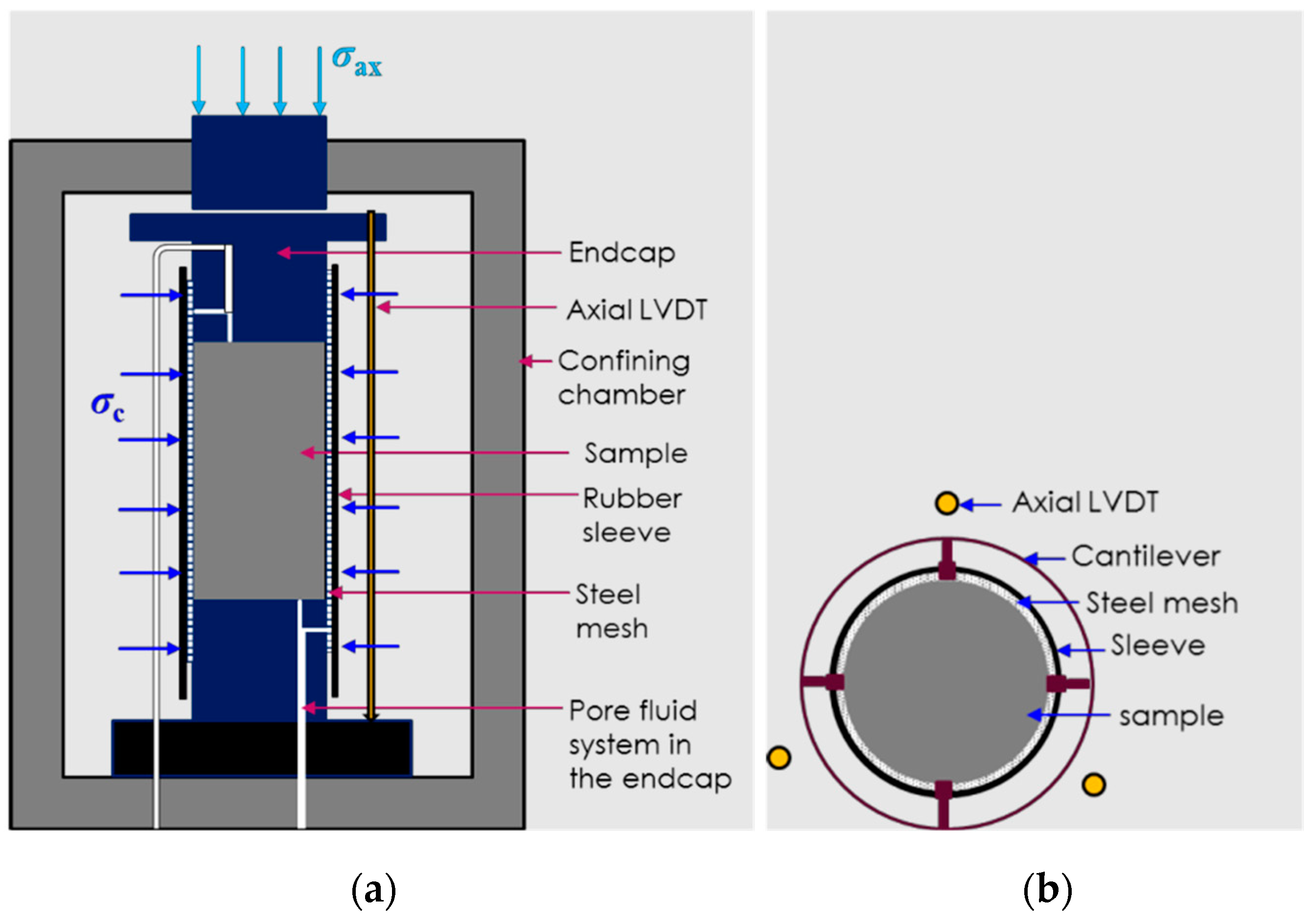
2.1. Triaxial Testing on Small Specimens

A series of 5 triaxial tests were conducted, going from unconfined compression strength test (UCS) to consolidated isotropic undrained tests (CIU) at confining stresses of 10 and 15 MPa. The tests were performed using the SMASH triaxial cell (an in-house custom-made cell) at the Formation Physics Laboratory of SINTEF, in Trondheim [17]. This cell is a downscaled version that accepts cylindrical plugs with dimensions of approximately 15 mm in diameter and 30 mm in length. The cylindrical plugs were drilled from a larger block with the help of oil used to cool the rock and remove cuttings. Then, the samples were enclosed in shrink sleeves and stored in Marcol oil to further protect them from drying, and other chemico-osmotic effects. Polishing of end surfaces to ensure parallelism was undertaken, as it significantly limits surface damage and stress concentrations in the sample inserted in the load frame, which may result from non-uniform contact with the pistons. Larger samples were prepared for the tests with fluid substitution, i.e., first exposure to brine, then replacing the fluid with supercritical CO2 (scCO2) dissolved in brine. These plugs had dimensions of 1” in diameter by 2” in length (25.4 cm × 50.8 cm). For more efficient and rapid saturation by fluid diffusion, a central hole 1.5 mm in diameter was drilled axially through the samples. Moreover, the external surfaces of the sample were covered with highly permeable metal mesh. A schematic drawing of the cell is shown in Figure 1, with instrumentation to measure axial and radial deformations. In addition, ultrasonic velocity (Pv) was measured with piezo-electric transducers installed in the load frame pistons. An MTS load frame with 50 kN load capacity was used in these tests.
Due to the very low permeability of these shale samples, of the order of a few nD, long consolidation times were necessary once the desired initial deviatoric stress was applied. Thus, triaxial test duration was up to 70 h, and the test with fluid exchange was conducted for 600 h in total. Unload–reload loops were performed in all tests to assess elastic properties; similarly, all tests were terminated by failing the specimens under a monotonical increase in axial strain.

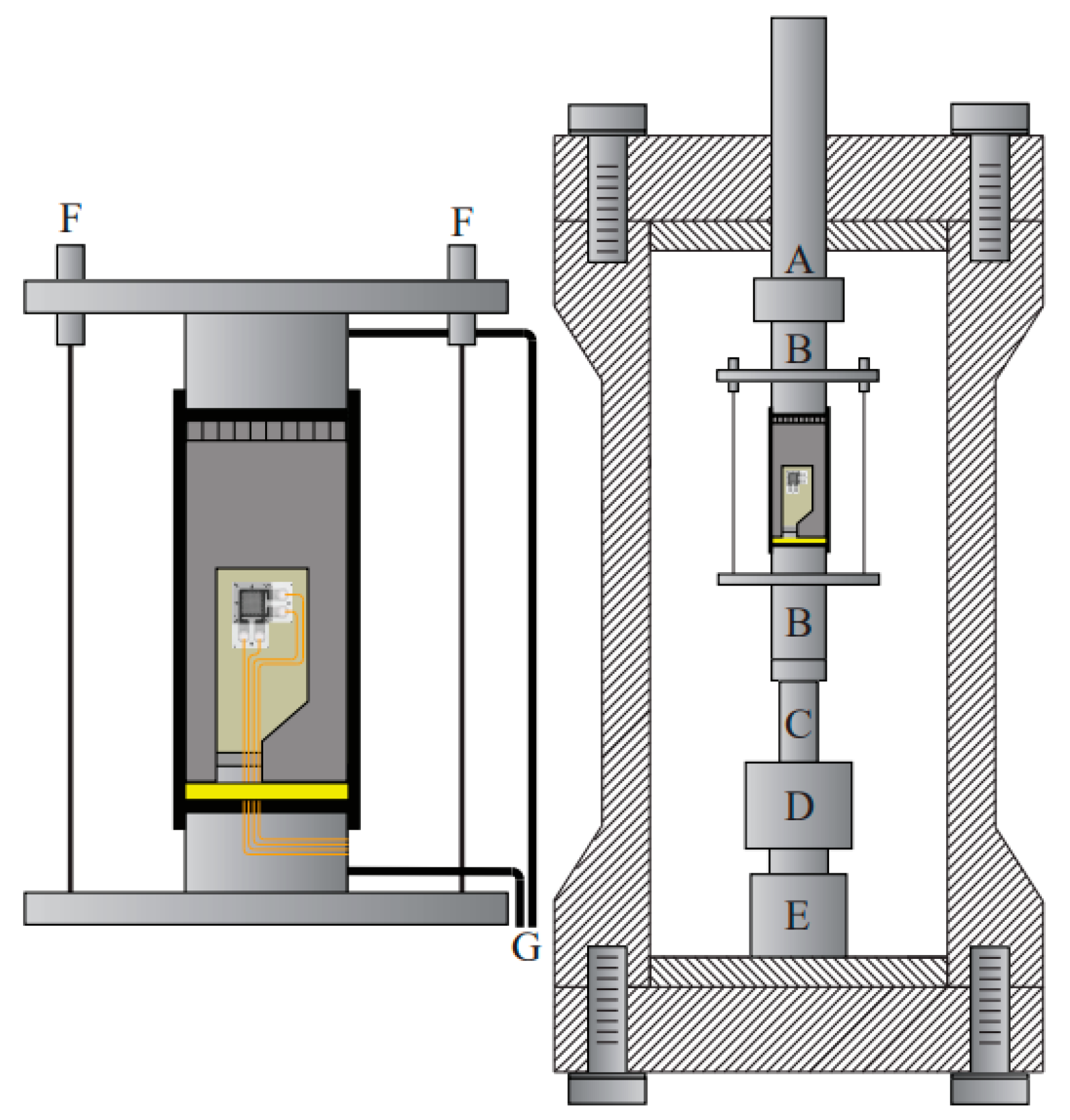
2.2. Non-Destructive Stiffness Test with CO2 Exposure

In this test, the low-frequency rig developed at SINTEF was used in a novel manner, as a non-destructive, repeated cyclic stiffness test, with pore fluid exchange in the course of testing [15]. The low-frequency setup allows the investigator to characterize the dispersion-related properties of rock cores by sweeping the sample with forced axial oscillations at frequencies ranging from less than 1 Hz to several kHz [18]. This is performed on 2.54 cm-diameter (1”) times 5.08 (2”) cm-long cylindrical plugs, while maintaining the desired applied stress. The setup is very versatile and allows the user to measure the dynamic Young’s modulus and Poisson’s ratio at seismic frequencies and compare these to P- and S-wave velocity measurements at ultrasonic frequencies (as in the MTS load frame described above). A schematic drawing of the cell is shown in Figure 2. The shale cylindrical specimen has strain gauges glued onto it and is placed between two sintered plates. The sample is surrounded with metal mesh to ensure efficient pore fluid distribution on the rock surface, inside the rubber sleeve isolating it from the oil exerting confining stress [19].
During the fluid exchange procedure, being a part of the test performed on Draupne shale, the values of confining stress, pore pressure and axial stress were kept constant and close to field values. This guaranteed that no fracturing occurred during unloading or reloading, since the fluid switch was made without changing the applied stresses and pore pressure. The test consisted of three phases:
(i)
Consolidation phase with no fluid flow.
(ii)
Exposure to brine with flow rate of 0.025 mL/min.
(iii)
Exposure to scCO2 dissolved in brine at 0.025 mL/min.
As in the triaxial test with CO2 exposure, a central, axial hole was also drilled in the specimen used for low-frequency testing and exposure. This ensured accelerated diffusion of pore fluid into the specimen by substantially increasing the available exposed surface. For the data of interest in the exposure test, i.e., elastic moduli, a frequency of 25 Hz and sampling interval of 60 s were chosen. In addition, P- and S-waves were recorded with intervals of 900 s.

2.3. Shear Strength Measurement with the PUNCH Technique

The technique relies on preparing thin disks from the Draupne shale, with a diameter of 15 mm and thickness of approximately 3 mm. As in the previous two techniques, the shale disks were prepared such that their bedding plane normal was parallel to the cylindrical plug axis, from which the disks were drilled. The disks were polished with sandpaper to ensure parallelism of their end surfaces. At all times, the disks were kept insulated from the atmospheric conditions by immersing them in inert oil. Fifty-seven disks were thus prepared, with three samples being tested for each of the chosen exposure fluids and exposure times. As far as possible, exposure tests were carried out immediately after completion of sample preparation. Six different fluids were investigated in the exposure tests: brine, CO2 gas dissolved in brine, supercritical CO2 (scCO2) dissolved in brine, dry gaseous CO2, dry scCO2, and air at room conditions. For reference, some disks were immediately tested for shear strength to give initial values for the rest of exposure tests. Each investigated exposure fluid required nine shale specimens to cover different fluid exposure periods prior to destructive strength testing. Three disks were retrieved from fluid exposure after 1, 2, and 7 days of exposure and tested for shear strength; this allowed us to investigate fluid exposure effect on strength as a function of exposure time.
Shear strength was measured using the punch technique, which employs an in-house tool developed at SINTEF [20]. The tested shale disk is maintained clamped between two pistons, as shown in Figure 3. Additional pistons make contact with the shale disk through a central hole in the apparatus. The top central piston is in contact with the load frame and, during the test, cuts a hole of 5 mm in diameter in the shale disk. Here, an MTS load frame with 10 kN capacity was used, with a fixed deformation rate of 0.15 mm/min. The forced shear deformation occurring along the axial direction allows measuring shear strength to be the peak force required to create a hole through the sample, divided by the area of the cylindrical cut. Three samples were used to calculate the shear strength for each exposure fluid and time.

3. Results

In this section, the results of various tests carried out on the Draupne shale are compared, with emphasis put on the CO2-exposure results.

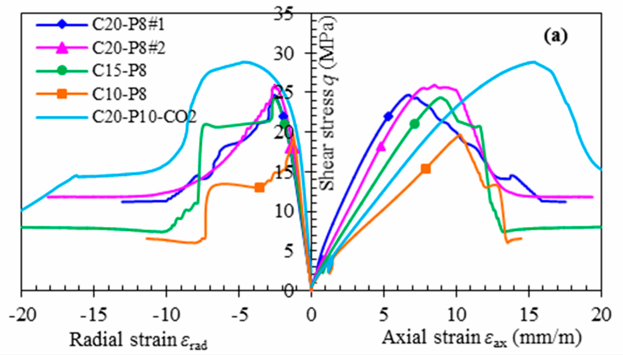
3.1. Triaxial Testing on Small Specimens

The evolution of peak strength with confining stress is shown in Figure 4. The stress–strain plots for each experiment are annotated with CX-PY, where X stands for confining stress, P for pore pressure, and X and Y represent their corresponding values. The last test where brine was substituted with CO2-saturated brine at 20 MPa confining stress and 10 MPa pore pressure was performed is named C20-P10-CO2.
Results show a Poisson’s ratio of 0.3 and a Young’s modulus of 4.5 GPa, with a calculated UCS of 23 MPa and friction angle of 23°. Looking at the CO2-exposure test, the undrained bulk modulus decreased from 3 to 2 GPa after switching from brine to scCO2-saturated brine, with the Skempton B coefficient also being reduced from 0.5 to 0.3. However, it could be that this is due to CO2 coming out of solution in the phase of the test in which isotropic compression cycles were run. After the fluids were substituted, the Young’s modulus was measured to be 4.2 GPa, while the Poisson’s ratio decreased to 0.2. However, the peak stress was somewhat higher: 29 MPa (see Figure 4).

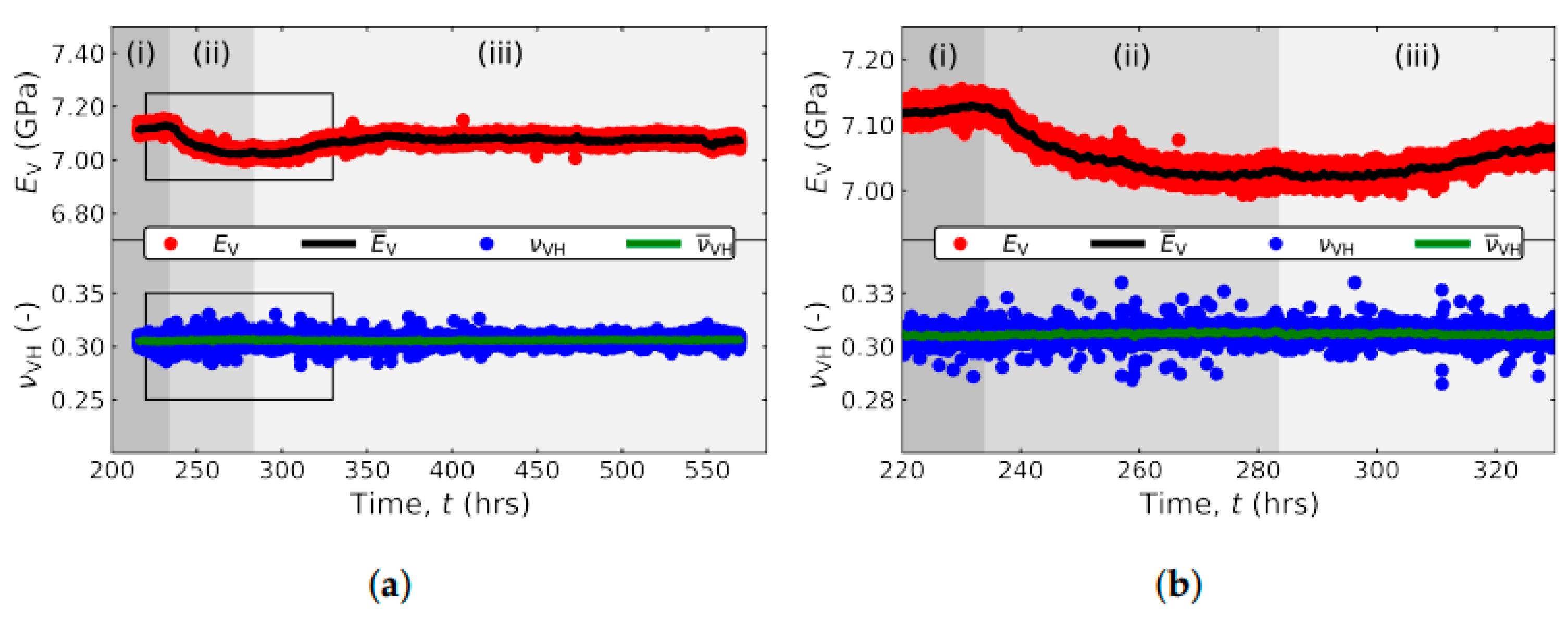
3.2. Low-Frequency Stiffness Test with CO2 Exposure

In the low-frequency setup, the substantial number of observations allows for robust data averaging and continuous monitoring of Young’s modulus evolution. Hence, it is possible to determine the moment when the sample exposed to a certain pore fluid reaches equilibrium and can be exposed to yet another pore medium (Figure 5).
We observed a reduction in measured stiffness caused by brine exposure. After exposure to scCO2 dissolved in brine (period (iii) in Figure 5), there appears to be a slight stiffening of the rock. This is contrary to the softening reported in Section 3.1, but agrees with the higher strength measured after CO2 exposure in the triaxial test, if we assume correlation between stiffness and compressive strength. However, the magnitude of stiffness change is very small, both after the exposure to brine or to scCO2-saturated brine, and the impact of the fluids can be classified as negligible. This is a positive result that proves that exposure to the stored CO2 does not alter the caprock and that the fluid-related risk of storage in reservoirs sealed by Draupne shale is limited.

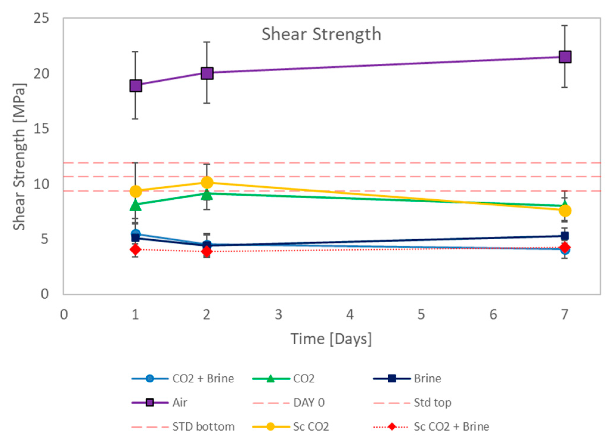
3.3. Shear Strength Measurement with the Punch Technique

Figure 6 summarizes all shear strength measurements obtained with the punch method for the different exposure fluid combinations. Due to the small dimensions of the samples, we were able to repeat the same tests several times—this allowed us to estimate the experimental uncertainty. The reference material (“as received” native brine saturation) had cohesion of approximately 10 MPa. Taking a friction angle of 23° from the triaxial tests, we can estimate a UCS value of 30 MPa, which is higher than 23 MPa reported in Section 3.1.
The results show that the largest impact of fluid exposure is expected in the first day, followed by a period of no significant changes, at least in the one-week timeframe. No significant difference between exposure to only brine or CO2-saturated brine was observed, either. It would thus seem that weakening is due to the degree of water saturation rather than to a lower pH effect. This is confirmed when looking at the opposite case of strengthening, where brine saturation reduction obtained by exposure to dry air yields the strongest sample, while exposure to gaseous or supercritical dry CO2 does not seem to significantly affect the Draupne shale.

4. Discussion and Conclusions

Three different experimental techniques have been used to assess the effect of CO2 exposure on the mechanical properties of the Draupne shale. Employing these three techniques allowed us to compensate for the shortcomings of individual methods and significantly increase the confidence in the validity of the results. None of the tests show a significant weakening caused by exposure to CO2-saturated brine compared to standard brine, suggesting that the exposure to CO2 does not compromise the strength of the cap rock. However, slow diffusion of CO2 into the caprock may cause changes to mechanical properties of overburden pore fluid. This in turn can affect the poroelastic parameters of the overburdened rocks (i.e., Skempton’s parameter B) and, consequently, the magnitude of undrained pore pressure changes resulting from further stress state alterations (further injections, fault activity, time-delayed pressure equilibration, etc.). As a result, the effective stresses in the cap rock may be significantly different from their modeled values, which may result in unexpected degradation of cap rock integrity. Hence, we suggest that the impact of CO2 on the poroelastic properties of the cap rock should also be studied.

Author Contributions

Conceptualization, P.C. and M.D.; methodology, P.C., L.E., N.A. and M.H.B.; validation, P.C., M.D., L.E., N.A. and M.H.B.; formal analysis, L.E., N.A. and M.H.B.; investigation, L.E., N.A. and M.H.B.; resources, P.C.; data curation, L.E., N.A., M.D. and M.H.B.; writing—original draft preparation, P.C. and M.D.; writing—review and editing, P.C. and M.D.; project administration, P.C.; funding acquisition, P.C. All authors have read and agreed to the published version of the manuscript.

Funding

This research was funded by the Research Council of Norway in the framework of the SPHINCSS—Stress Path and Hysteresis effects on Integrity of CO2 Storage Site Researcher Project # 268445. Additional funding was obtained through the NCCS Centre, under the Norwegian research program Centres for Environmentally Friendly Energy Research (FME).

Institutional Review Board Statement

Not applicable.

Informed Consent Statement

Not applicable.

Data Availability Statement

All collected data in the work described in this paper is available upon request from the authors and kept in a repository at SINTEF Industry.

Acknowledgments

The authors acknowledge the following partners for their contributions: Aker Carbon Capture, Allton, Ansaldo Energia, Baker Hughes, CoorsTek Membrane Sciences, Equinor, Fortum Oslo Varme, Gassco, KROHNE, Larvik Shipping, Lundin Norway, Norcem, Norwegian Oil and Gas, Quad Geometrics, Stratum Reservoir, TotalEnergies, Vår Energi, Wintershall DEA, and the Research Council of Norway (257579/E20).

Conflicts of Interest

The authors declare no conflict of interest. The funders had no role in the design of the study; in the collection, analyses, or interpretation of data; in the writing of the manuscript; or in the decision to publish the results.

References

  1. Paris Agreement. Report of the Conference of the Parties to the United Nations Framework Convention on Climate Change (21st Session, 2015: Paris); Retrieved December; HeinOnline: Richardson, TX, USA, 2015; Volume 4, p. 7. [Google Scholar]
  2. Geden, O.; Scott, V.; Palmer, J. Integrating carbon dioxide removal into EU climate policy: Prospects for a paradigm shift. WIREs Clim. Chang. 2018, 9, e521. [Google Scholar] [CrossRef]
  3. Allen, M.; Antwi-Agyei, P.; Aragon-Durand, F.; Babiker, M.; Bertoldi, P.; Bind, M.; Brown, S.; Buckeridge, M.; Camilloni, I.; Cartwright, A.; et al. Technical Summary: Global Warming of 1.5° C. An IPCC Special Report on the Impacts of Global Warming of 1.5° C above Pre-industrial Levels and Related Global Greenhouse Gas Emission Pathways, in the Context of Strengthening the Global Response to the Threat of Climate Change, Sustainable Development, and Efforts to Eradicate Poverty; Intergovernmental Panel on Climate: Geneva, Switzerland, 2019. [Google Scholar]
  4. Chadwick, R.; Zweigel, P.; Gregersen, U.; Kirby, G.; Holloway, S.; Johannessen, P. Geological reservoir characterization of a CO2 storage site: The Utsira Sand, Sleipner, Northern North Sea. Energy 2004, 29, 1371–1381. [Google Scholar] [CrossRef]
  5. Ringrose, P.S. The CCS hub in Norway: Some insights from 22 years of saline aquifer storage. Energy Procedia 2018, 146, 166–172. [Google Scholar] [CrossRef]
  6. Cerasi, P.; Stroisz, A.M.; Sønstebø, E.; Stanchits, S.; Oye, V.; Bauer, R. Experimental investigation of injection pressure effects on fault reactivation for CO2 storage. Int. J. Greenh. Gas Control 2018, 78, 218–227. [Google Scholar] [CrossRef]
  7. Ringrose, P.; Oldenburg, C. Mission Innovation task force reports on enabling Gigatonne-scale CO2 storage. First Break 2018, 36, 67–72. [Google Scholar] [CrossRef]
  8. Tawiah, P.; Duer, J.; Bryant, S.L.; Larter, S.; O’Brien, S.; Dong, M. CO2 injectivity behaviour under non-isothermal conditions–Field observations and assessments from the Quest CCS operation. Int. J. Greenh. Gas Control 2019, 92, 102843. [Google Scholar] [CrossRef]
  9. Gheibi, S.; Holt, R.M.; Vilarrasa, V. Effect of faults on stress path evolution during reservoir pressurization. Int. J. Greenh. Gas Control 2017, 63, 412–430. [Google Scholar] [CrossRef]
  10. Rongved, M.; Cerasi, P. Simulation of Stress Hysteresis Effect on Permeability Increase Risk Along A Fault. Energies 2019, 12, 3458. [Google Scholar] [CrossRef]
  11. Skurtveit, E.; Grande, L.; Ogebule, O.Y.; Gabrielsen, R.H.; Faleide, J.I.; Mondol, N.H.; Maurer, R.; Horsrud, P. Mechanical Testing and Sealing Capacity of the Upper Jurassic Draupne Formation, North Sea. In Proceedings of the 49th US Rock Mechanics/Geomechanics Symposium, San Francisco, CA, USA, 28 June–1 July 2015; OnePetro: Richardson, TX, USA, 2015. [Google Scholar]
  12. Duda, M.I.; Bakk, A.; Holt, R.M.; Stenebråten, J.F. Anisotropic Poroelastic Modelling of Depletion-Induced Pore Pressure Changes in Valhall Overburden. Norwegian University of Science and Technology: Trondheim, Norway, 2022; Manuscript submitted for publication. [Google Scholar]
  13. Cerasi, P.; Holt, R.M.; Lavrov, A.; Stenebråten, J.F. Investigation of geomechanical and rock physics aspects related to underground storage and monitoring of CO2. J. Ind. Geophys. Union 2016, 1, 26–29. [Google Scholar]
  14. Nes, O.M.; Sonstebo, E.F.; Horsrud, P.; Holt, R.M. Dynamic and static measurements on mm-size shale samples. In SPE/ISRM Rock Mechanics in Petroleum Engineering; OnePetro: Richardson, TX, USA, 1998. [Google Scholar]
  15. Agofack, N.; Cerasi, P.; Stroisz, A.; Rørheim, S. Sorption of CO2 and integrity of a caprock shale. In Proceedings of the 53rd US Rock Mechanics/Geomechanics Symposium, New York, NY, USA, 23–26 June 2019; OnePetro: Richardson, TX, USA, 2019. [Google Scholar]
  16. Rørheim, S.; Bhuiyan, M.H.; Bauer, A.; Cerasi, P.R. On the Effect of CO2 on Seismic and Ultrasonic Properties: A Novel Shale Experiment. Energies 2021, 14, 5007. [Google Scholar] [CrossRef]
  17. Nes, O.M.; Sonstebo, E.F.; Fjær, E.; Holt, R.M. Use of Small Shale Samples in Borehole Stability Analysis. In Proceedings of the Gulf Rocks 2004, The 6th North America Rock Mechanics Symposium (NARMS), Houston, TX, USA, 5–9 June 2004; OnePetro: Richardson, TX, USA, 2004. [Google Scholar]
  18. Szewczyk, D.; Bauer, A.; Holt, R.M. A new laboratory apparatus for the measurement of seismic dispersion under deviatoric stress conditions. Geophys. Prospect. 2016, 64, 789–798. [Google Scholar] [CrossRef] [Green Version]
  19. Lozovyi, S.; Bauer, A. Velocity dispersion in rocks: A laboratory technique for direct measurement of P-wave modulus at seismic frequencies. Rev. Sci. Instruments 2019, 90, 024501. [Google Scholar] [CrossRef] [PubMed]
  20. Stenebraten, J.F.; Sonstebo, E.F.; Lavrov, A.V.; Fjaer, E.; Haaland, S. The Shale Puncher-A Compact Tool for Fast Testing of Small Shale Samples. In Proceedings of the The 42nd US Rock Mechanics Symposium (USRMS), San Francisco, CA, USA, 29 June–2 July 2008; American Rock Mechanics Association; OnePetro: Richardson, TX, USA, 2008. [Google Scholar]
Figure 1. Triaxial cell for small samples. (a) axial cut schematically showing the positioning of the shale specimen, steel mesh to distribute pore fluid, surrounding rubber sleeve and fluid lines in the pistons; (b) cross section showing instrumentation consisting of linear variable displacement transducers (LVDTs) and cantilevers for axial and radial displacement, respectively.
Psf 04 00033 g001
Figure 2. Low-frequency rig at SINTEF. A: piston, B: top and bottom endcaps with embedded P- and S-wave transducers, C: piezoelectric force sensor, D: piezoelectric actuator, E: internal load cell, F: LVDTs, and G: pore fluid lines.
Psf 04 00033 g002
Figure 3. (a) Photograph of the assembled punching tool, (b) disassembled tool drawing showing the different pistons of the tool.
Psf 04 00033 g003
Figure 4. Stressstrain plot summarizing all triaxial tests performed on the Draupne shale.
Psf 04 00033 g004
Figure 5. (a) Young’s modulus (red dots, average: black line) and Poisson’s ratio (blue dots, average: green line) as a function of time. The three phases are (i) consolidation; (ii) flow of brine; (iii) flow of scCO2-saturated brine (see text in Section 2.2 above); (b) Zoom on the rectangular sections marked in (a).
Psf 04 00033 g005
Figure 6. Shear strength results from the punch testing campaign. The dashed horizontal lines show the values (measured plus minus standard deviation) for the reference shale samples, tested as is.
Psf 04 00033 g006
Publisher’s Note: MDPI stays neutral with regard to jurisdictional claims in published maps and institutional affiliations.

