
Phase Distribution in the Tip Clearance of a Multiphase Pump at Multiple Operating Points and Its Effect on the Pressure Fluctuation Intensity


Abstract
:1. Introduction
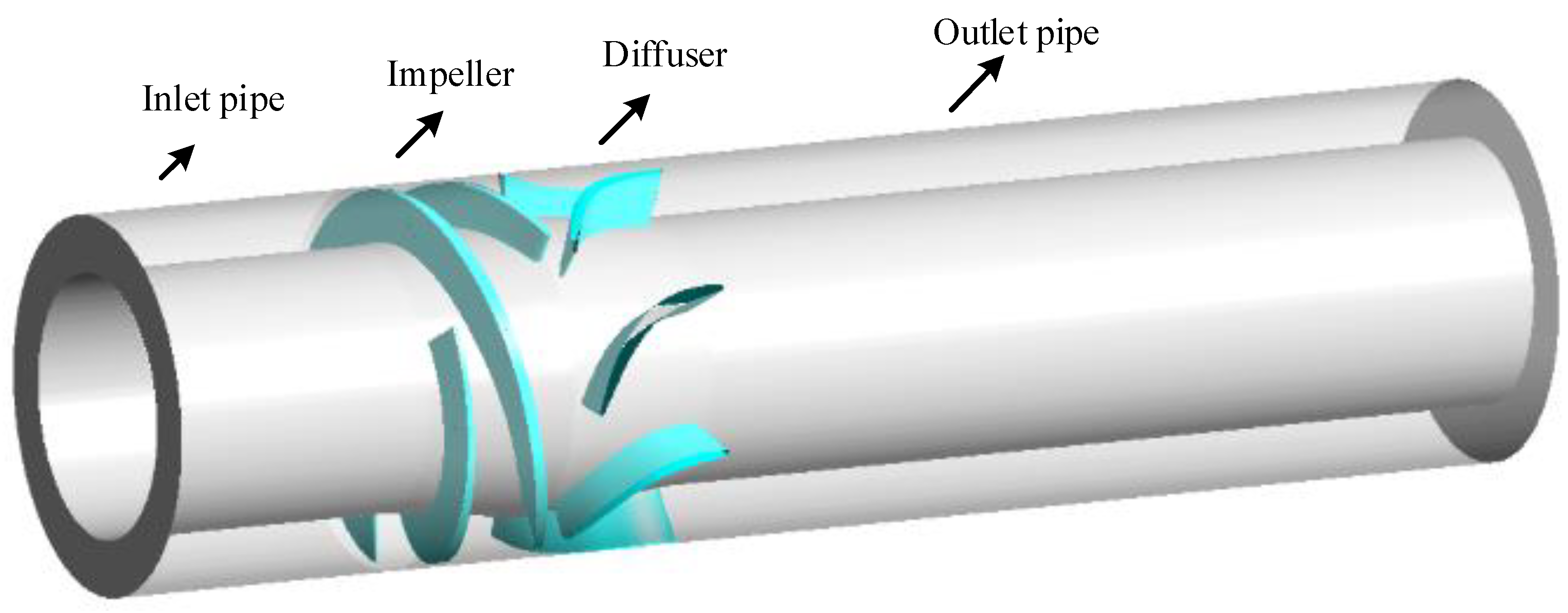
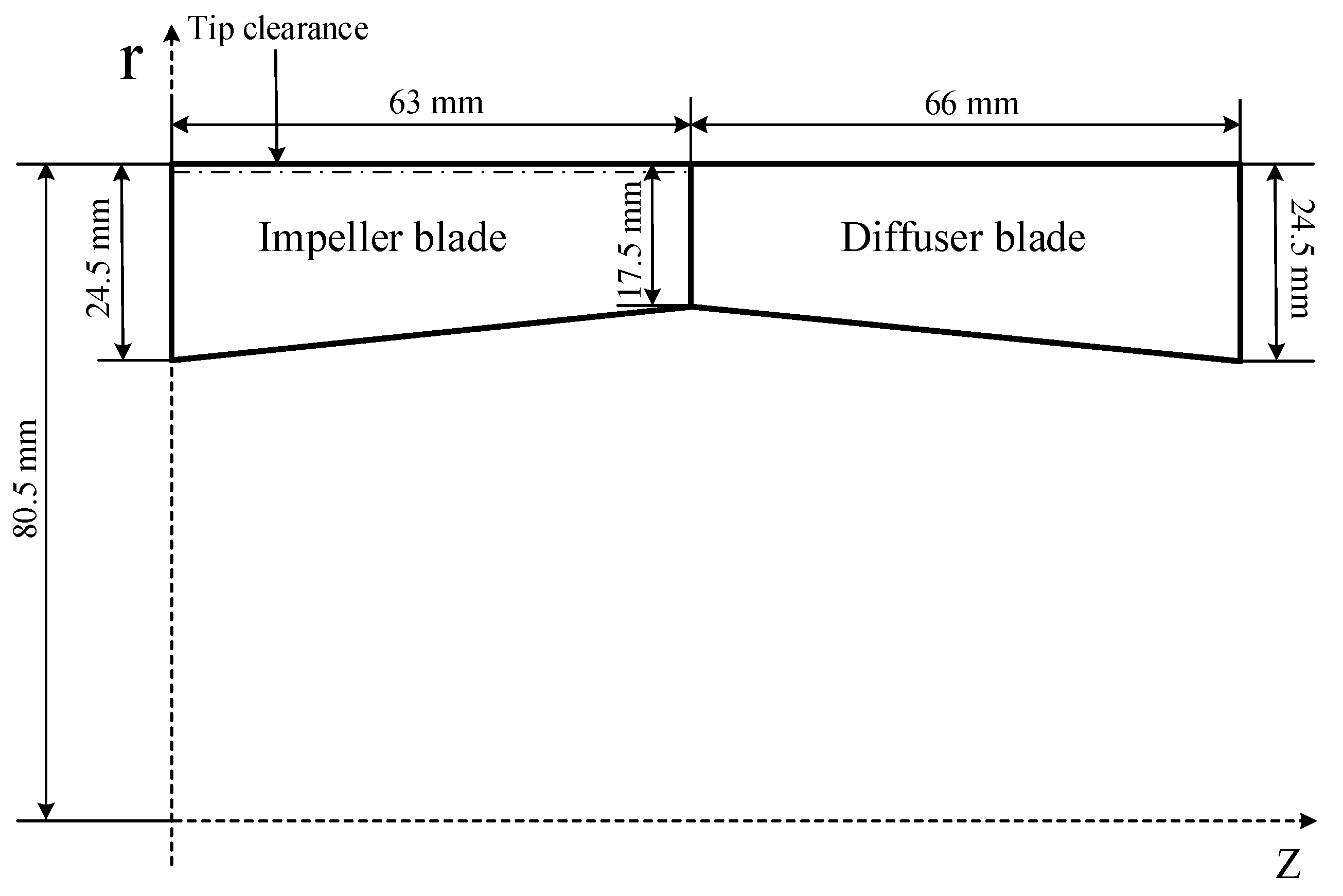
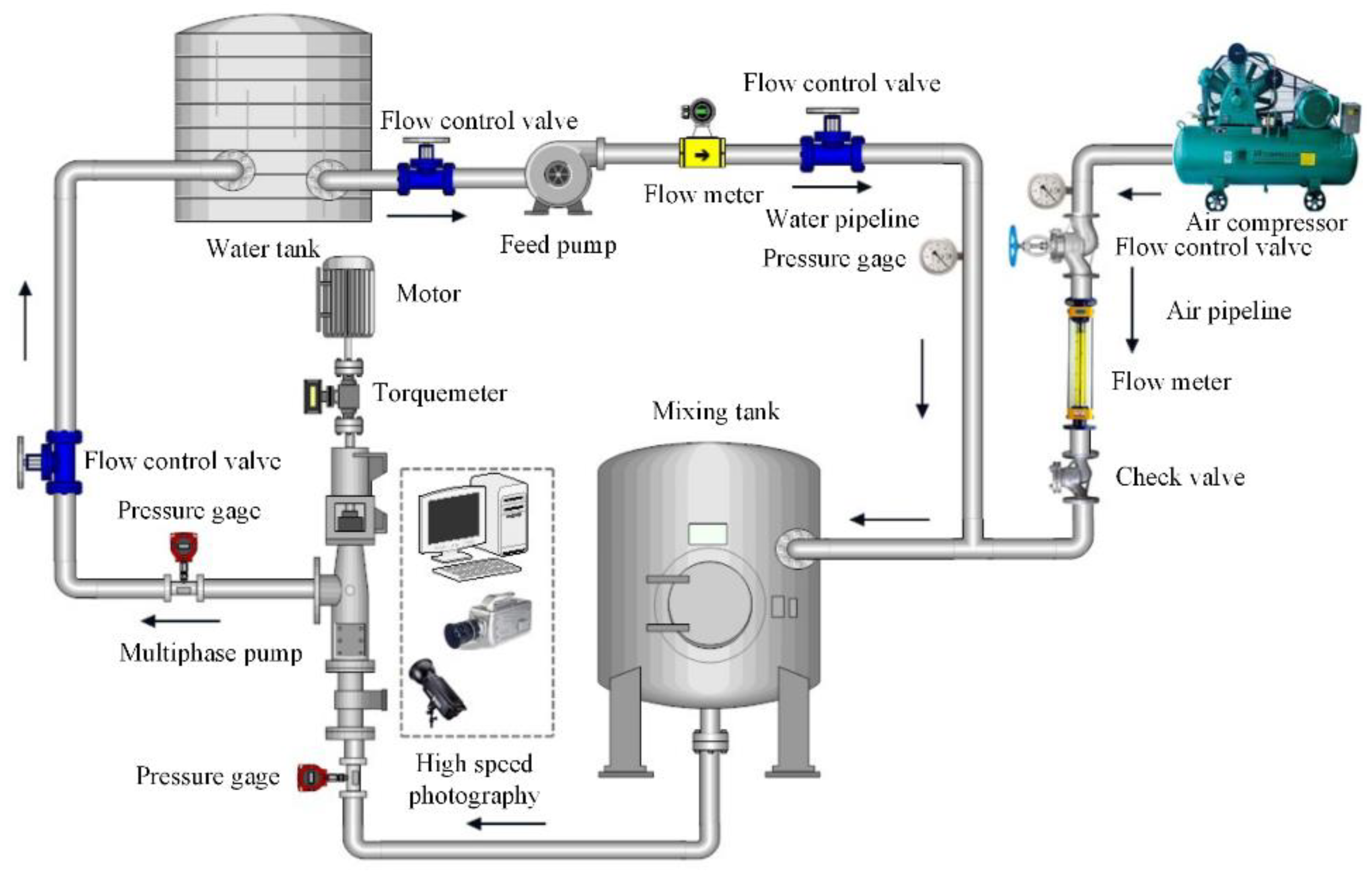
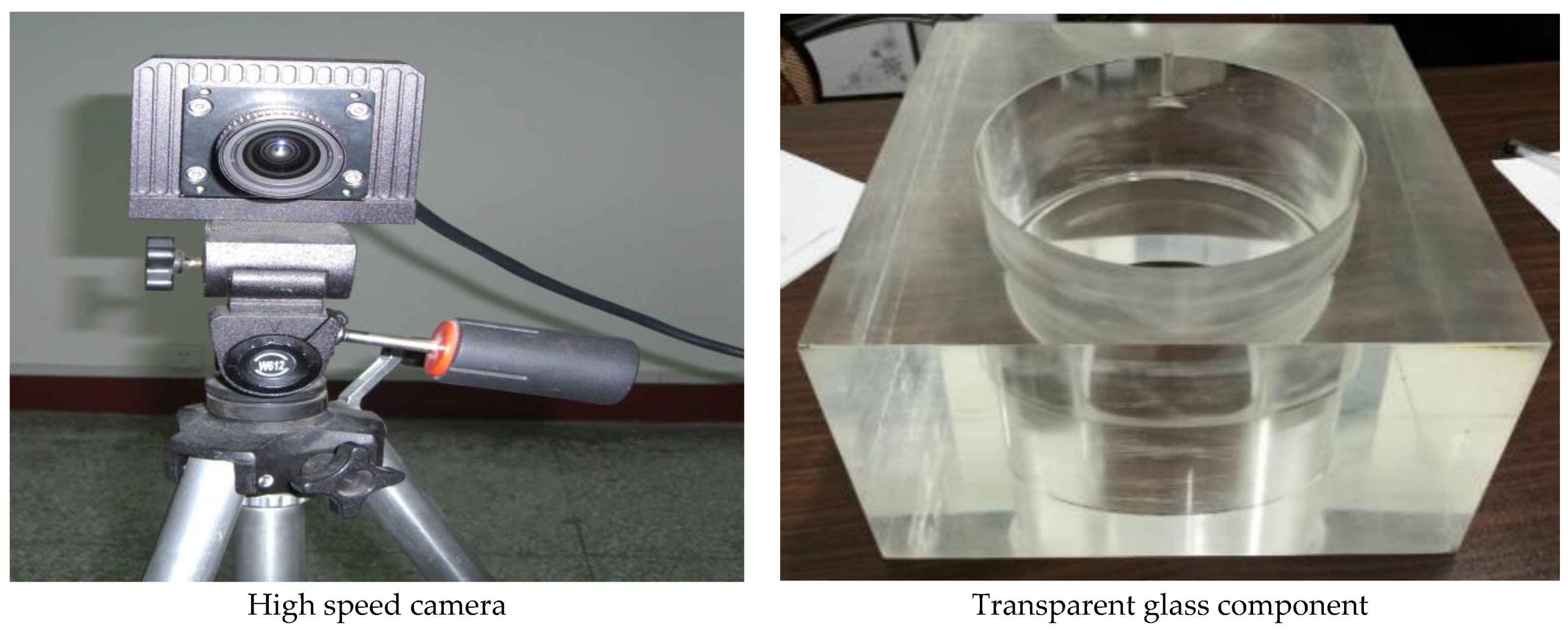
2. Research Object
3. Numerical Methods and Settings
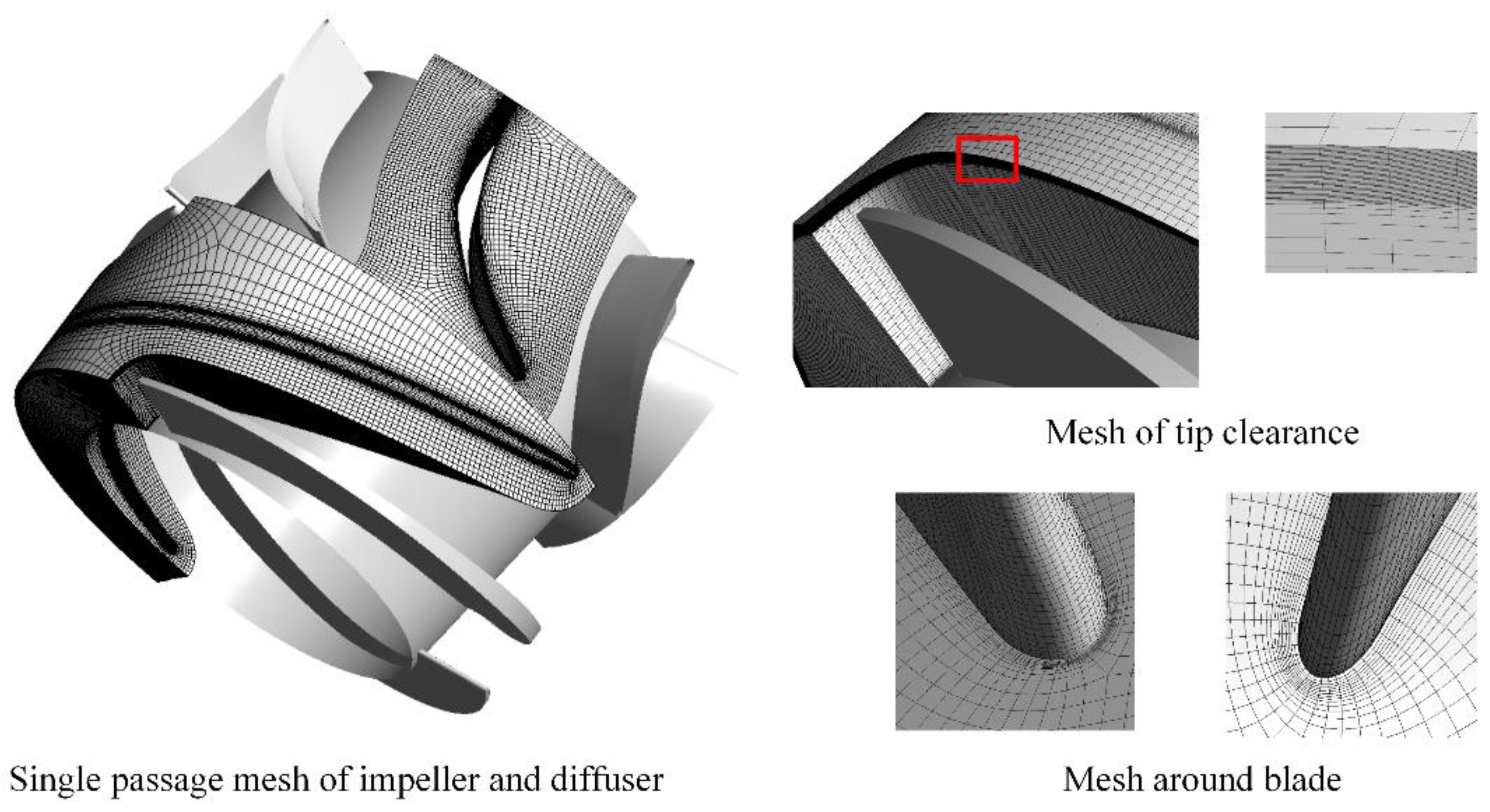
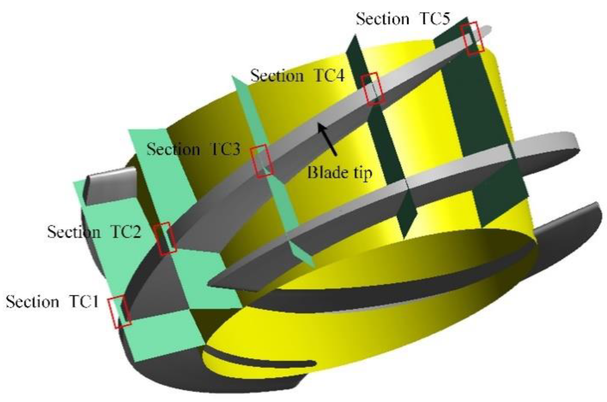
3.1. Mesh Arrangement
3.2. Mesh and Time Step Independence Verification
3.2.1. Mesh Independence Verification
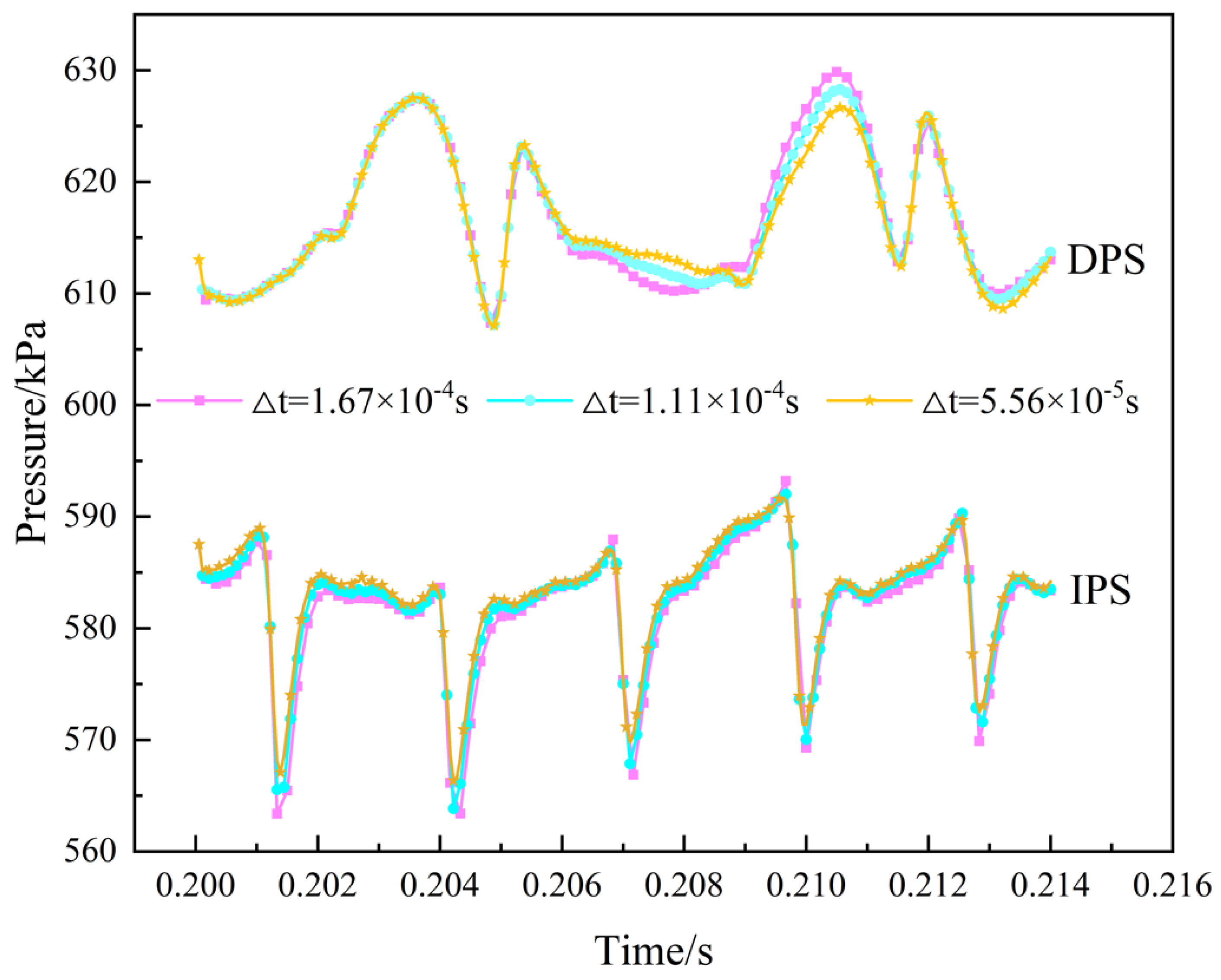
3.2.2. Time Step Independence Verification
3.3. Boundary Conditions and Settings
3.4. Numerical Method Verification
4. Result and Discussion
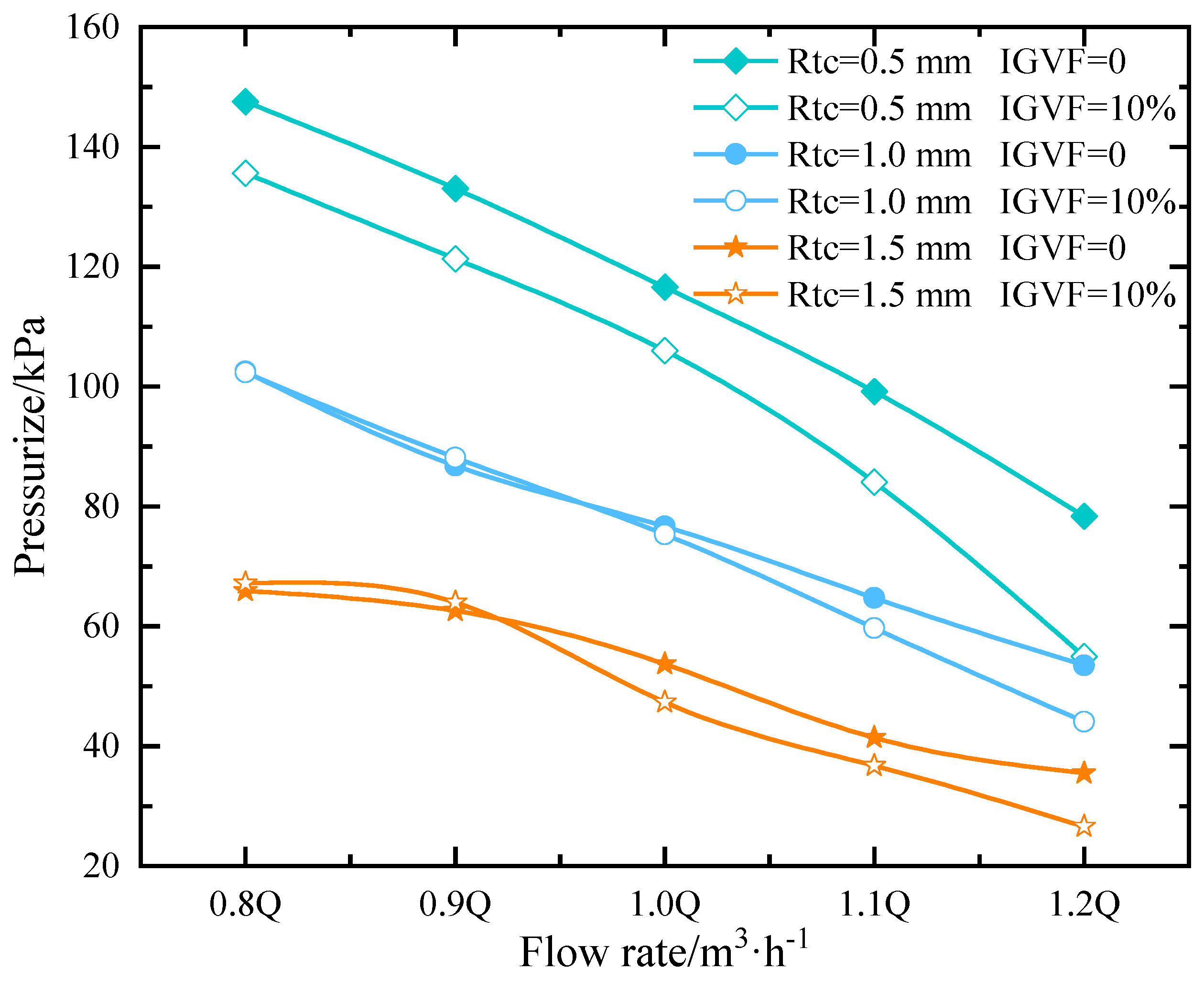
4.1. Multiphase Pump Pressurization Performance
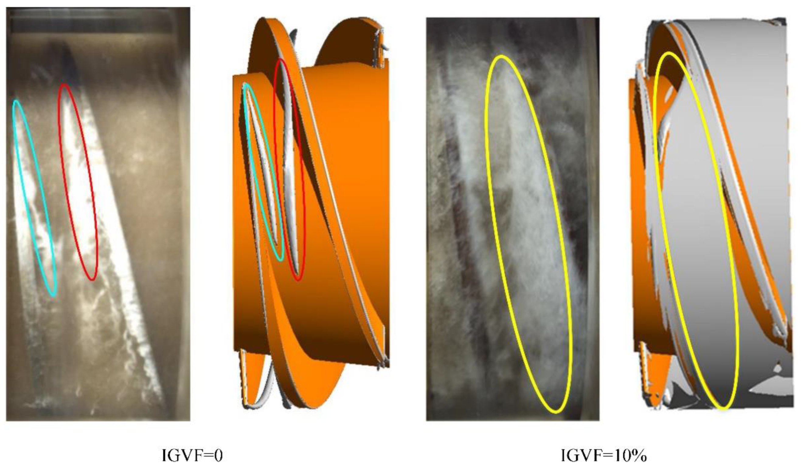
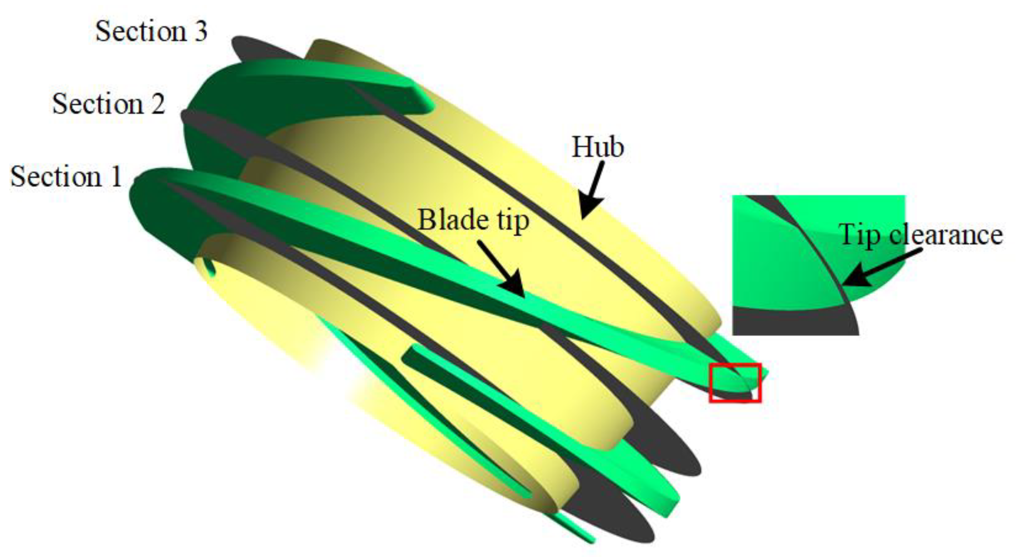
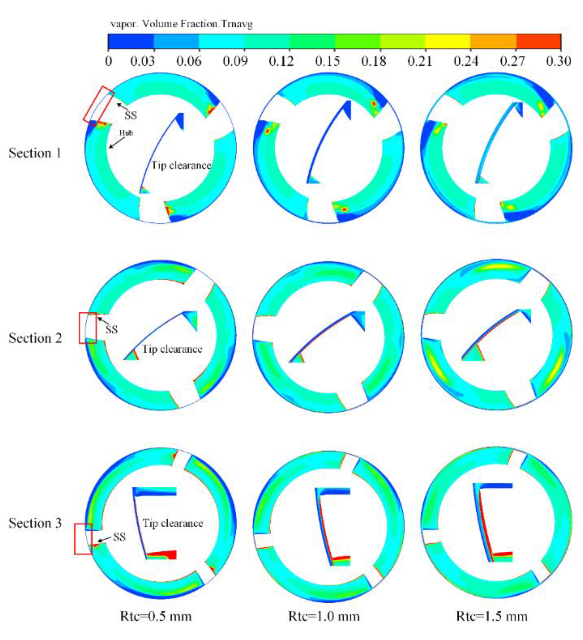
4.2. Gas Distribution in the Multiphase Pump Pressurization Unit
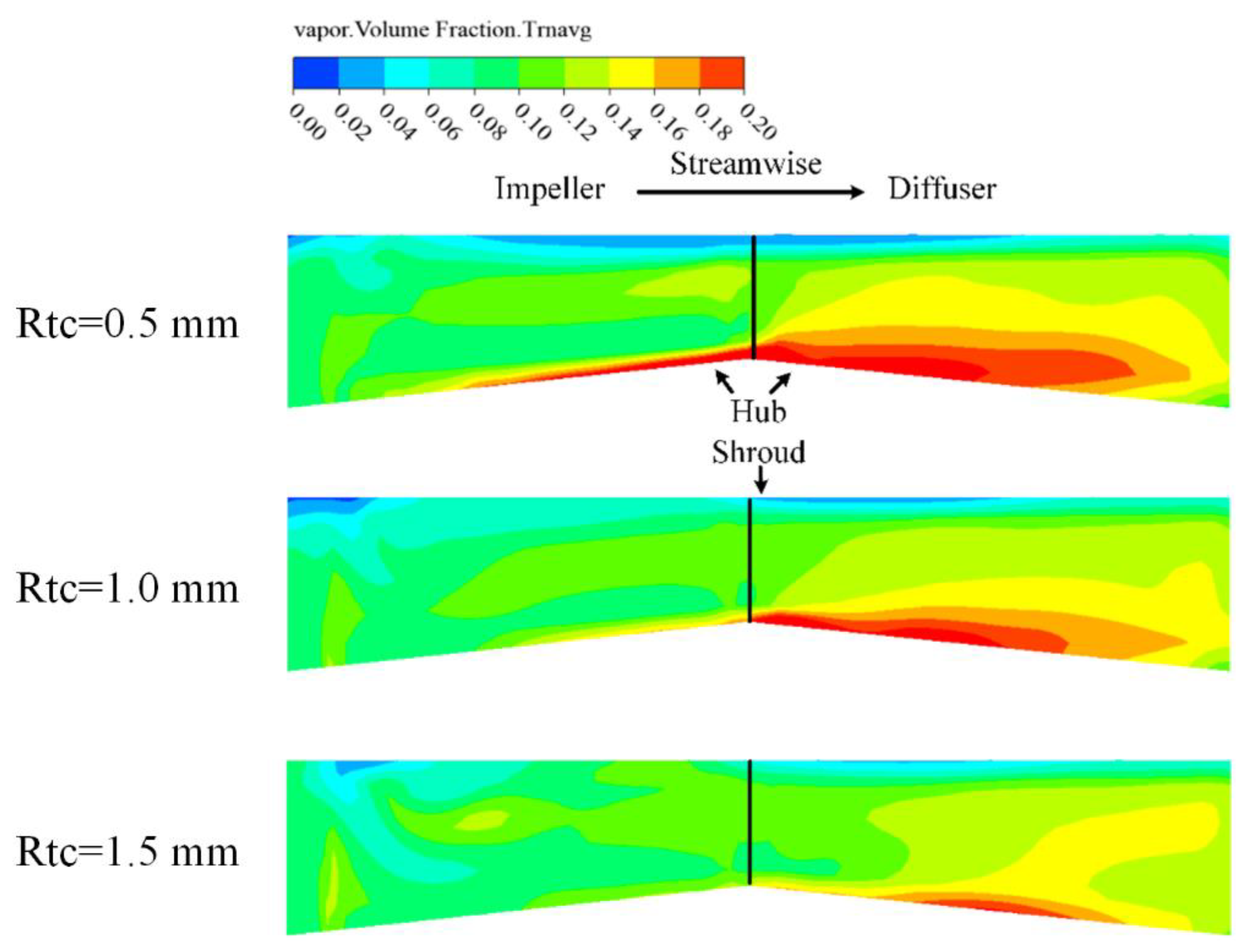
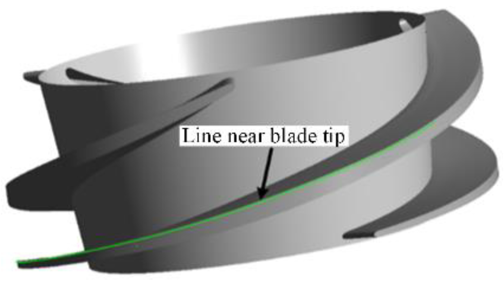
4.3. Gas-Liquid Two-Phase Velocity Slip in the Pressurization Unit
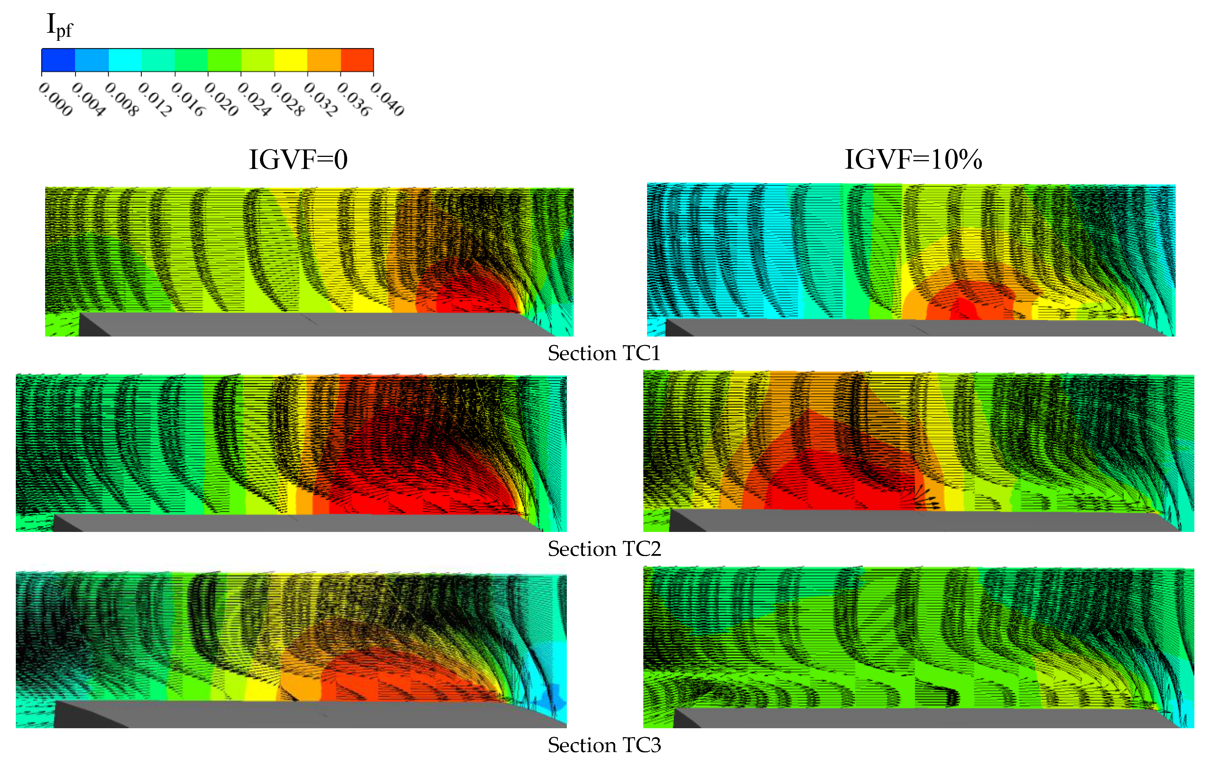
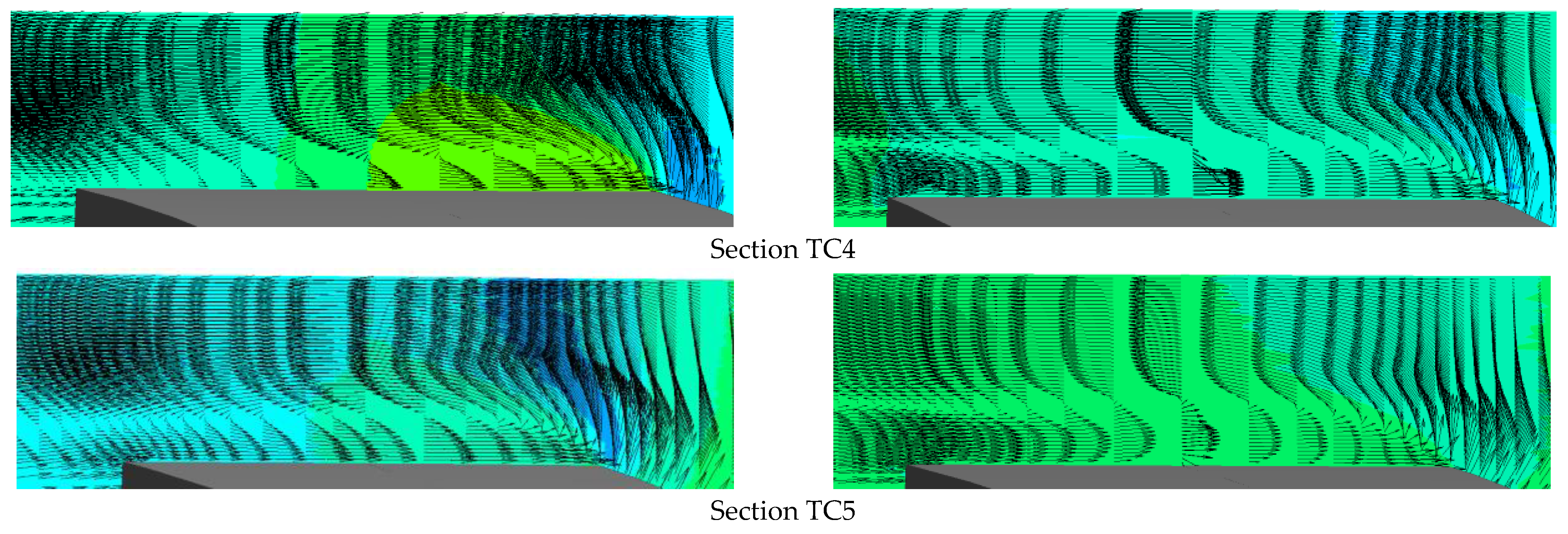
4.4. Pressure Fluctuation Intensity in the Tip Clearance
5. Conclusions
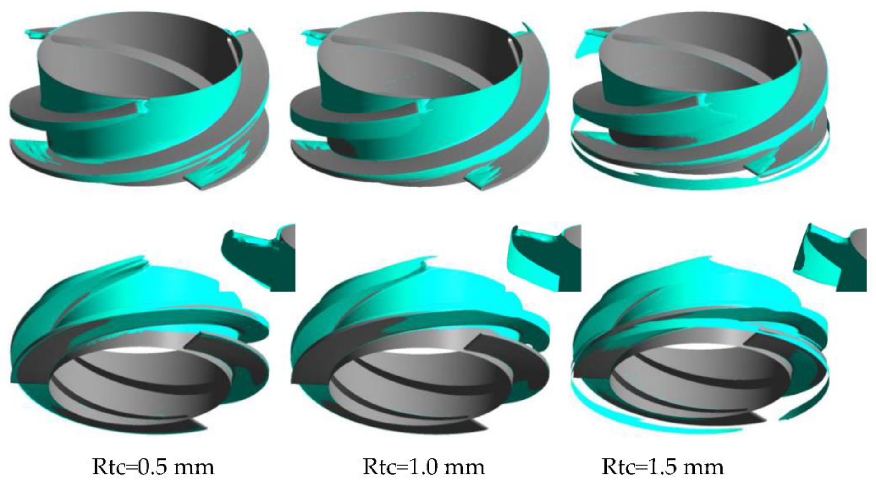
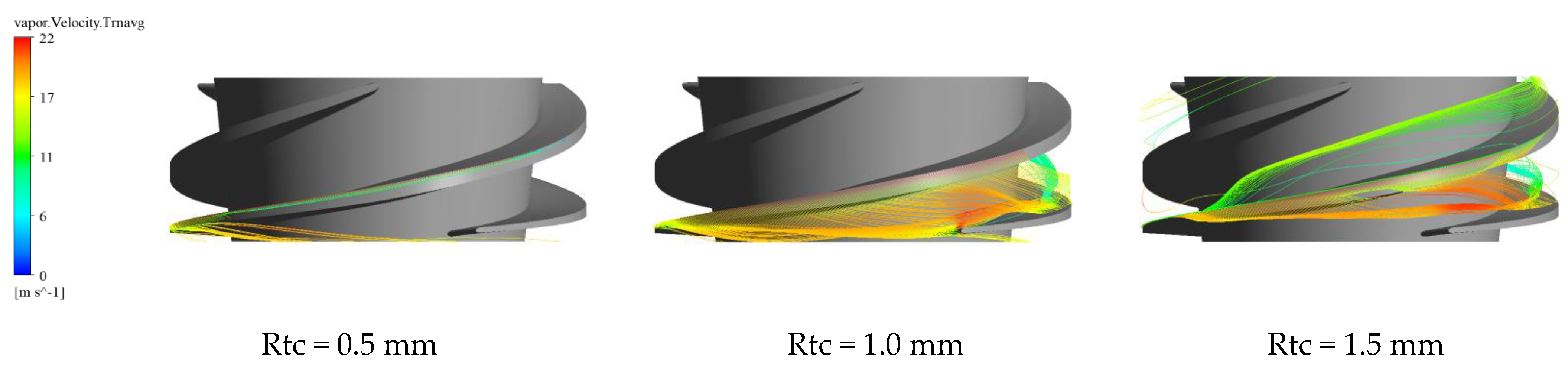
- As the tip clearance increases, the pump pressurization performance decreases rapidly. Meanwhile, when Rtc = 0.5 mm, the increase of the IGVF reduces the pump pressurization performance at all simulated operating points. However, when Rtc = 1.0 and 1.5 mm, the increase of the IGVF obviously reduces the pump pressurization performance only at large flow rate. In addition, the gas accumulation in the pump mainly occurs at the hub, blade SS, and tip clearance. Meanwhile, as the tip clearance increases, the gas accumulation in the tip clearance near the impeller blade TE becomes more serious, and the starting point of the gas TLV gradually moves backward.
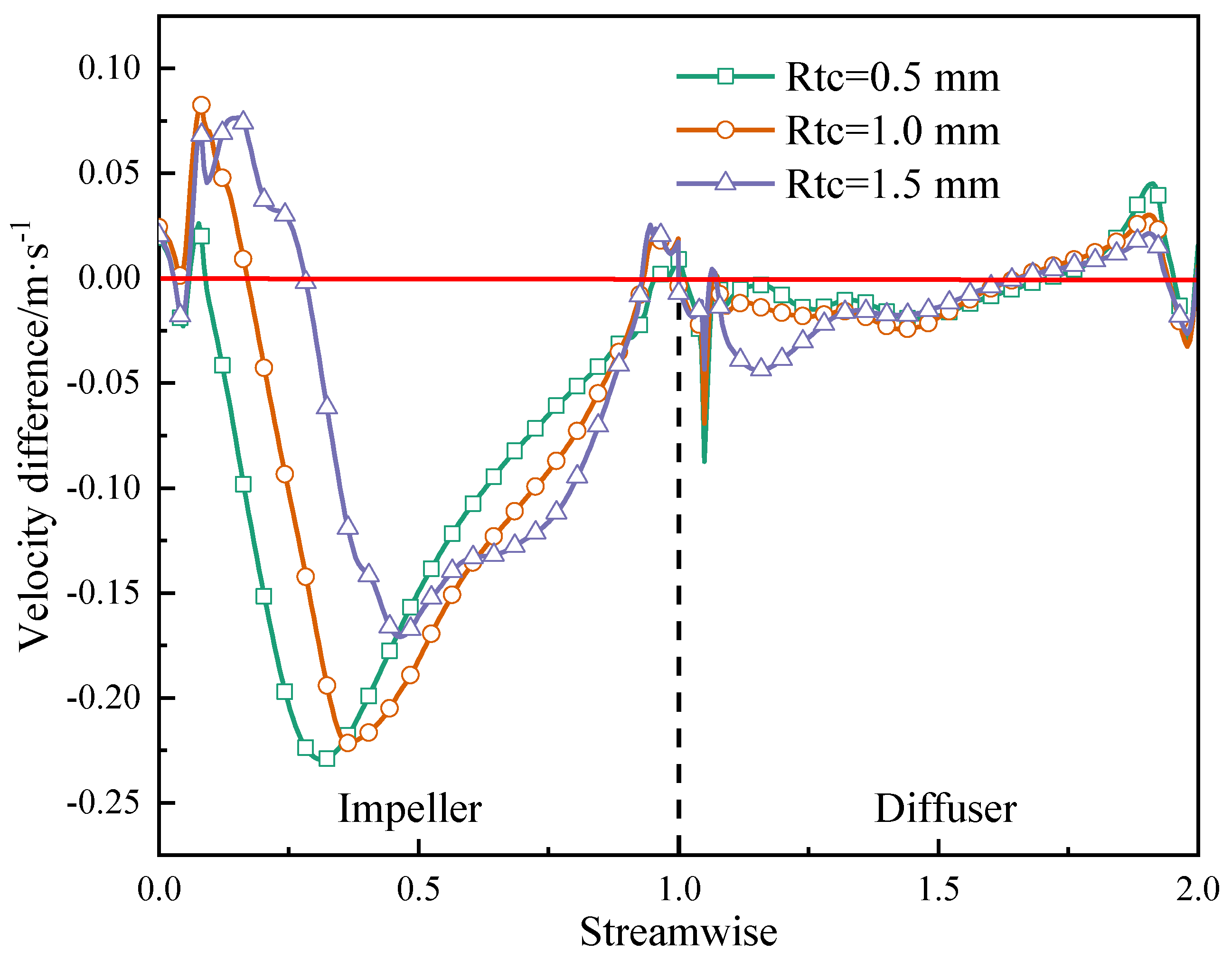
- Under different tip clearances, the velocity difference between the gas and liquid in the impeller is relatively large. However, in the diffuser it is relatively small. The maximum velocity difference between the gas and liquid is mainly near the impeller streamwise of 0.4. In the meantime, the tip clearance improves the gas-liquid two-phase distribution in the pump, that is, the larger the tip clearance is, the more uniform the gas-liquid two-phase in the pump becomes. However, an excessively large clearance increases hydraulic loss, so the optimal tip clearance needs comprehensive weight.
- The gas leads the maximum pressure fluctuation intensity in the tip clearance closer to the TLF outlet, and the flow separation also penetrates the entire tip clearance in advance. In addition, the flow separation degree in the tip clearance is largely affected by the gas.
Author Contributions
Funding
Institutional Review Board Statement
Informed Consent Statement
Data Availability Statement
Conflicts of Interest
References
- Kim, J.; Lee, H.; Yoon, J.; Lee, K.; Lee, Y.; Choi, Y. Multi Objective Optimization of a Multiphase Pump for Offshore Plants. In Proceedings of the ASME 2014 4th Joint Us-European Fluids Engineering Division Summer Meeting, Chicago, IL, USA, 3–7 August 2014. [Google Scholar]
- Suh, J.; Kim, J.; Choi, Y. Development of numerical Eulerian-Eulerian models for simulating multiphase pumps. J. Pet. Sci. Eng. 2018, 162, 588–601. [Google Scholar] [CrossRef]
- Zhang, J.; Zhu, H.; Yang, C.; Li, Y.; Wei, H. Multi-objective shape optimization of helico-axial multiphase pump impeller based on NSGA-II and ANN. Energy Convers. Manag. 2011, 52, 538–546. [Google Scholar] [CrossRef]
- Zhang, J.; Cai, S.; Li, Y.; Zhu, H.; Zhang, Y. Visualization study of gas-liquid two-phase flow patterns inside a three-stage rotodynamic multiphase pump. Exp. Therm. Fluid Sci. 2016, 70, 125–138. [Google Scholar] [CrossRef]
- Zhang, J.; Cai, S.; Zhu, H.; Zhang, Y. Experimental investigation of the flow at the entrance of a rotodynamic multiphase pump by visualization. J. Pet. Sci. Eng. 2015, 126, 254–261. [Google Scholar] [CrossRef]
- Suh, J.; Kim, J.; Choi, Y.; Kim, J.; Joo, W.; Lee, K. Multi-Objective Optimization of the Hydrodynamic Performance of the Second Stage of a Multi-Phase Pump. Energies 2017, 10, 1334. [Google Scholar] [CrossRef] [Green Version]
- Kim, J.; Lee, H.; Kim, J.; Choi, Y.; Yoon, J.; Yoo, I.; Choi, W. Improvement of Hydrodynamic Performance of a Multiphase Pump Using Design of Experiment Techniques. J. Fluids Eng. 2015, 137, 081301. [Google Scholar] [CrossRef]
- Tan, L.; Xie, Z.; Liu, Y.; Hao, Y.; Xu, Y. Influence of T-shape tip clearance on performance of a mixed-flow pump. Proc. Inst. Mech. Eng. Part A J. Power Energy 2018, 232, 386–396. [Google Scholar]
- Liu, Y.; Tan, L. Spatial-Temporal Evolution of Tip Leakage Vortex in a Mixed-Flow Pump with Tip Clearance. ASME J. Fluids Eng. 2019, 141, 081302. [Google Scholar] [CrossRef]
- Liu, Y.; Han, Y.; Tan, L.; Wang, Y. Blade rotation angle on energy performance and tip leakage vortex in a mixed flow pump as turbine at pump mode. Energy 2020, 206, 118084. [Google Scholar] [CrossRef]
- Liu, Y.; Tan, L. Theoretical Prediction Model of Tip Leakage Vortex in a Mixed Flow Pump with Tip Clearance. ASME J. Fluids Eng. 2020, 142, 021203. [Google Scholar] [CrossRef]
- Wu, H.; Tan, D.; Miorini, R.; Katz, J. Three-dimensional flow structures and associated turbulence in the tip region of a waterjet pump rotor blade. Exp. Fluids 2011, 51, 1721–1737. [Google Scholar] [CrossRef]
- Wu, H.; Miorini, R.; Katz, J. Measurements of the tip leakage vortex structures and turbulence in the meridional plane of an axial water-jet pump. Exp. Fluids 2011, 50, 989–1003. [Google Scholar] [CrossRef]
- Miorini, R.; Wu, H.; Katz, J. The Internal Structure of the Tip Leakage Vortex Within the Rotor of an Axial Waterjet Pump. ASME J. Turbomach. 2012, 134, 1–12. [Google Scholar] [CrossRef]
- Peng, X.; Xu, L.; Liu, Y.; Zhang, G.; Cao, Y.; Hong, F.; Yon, K. Experimental measurement of tip vortex flow field with/without cavitation in an elliptic hydrofoil. J. Hydrodyn. 2017, 29, 939–953. [Google Scholar] [CrossRef]
- Shen, X.; Zhang, D.; Xu, B.; Jin, Y.; Shi, W.; van Esch, B. Experimental Investigation of the Transient Patterns and Pressure Evolution of Tip Leakage Vortex and Induced-Vortices Cavitation in an Axial Flow Pump. ASME J. Fluids Eng. 2020, 142, 1–11. [Google Scholar]
- Zhang, J.; Fan, H.; Zhang, W.; Xie, Z. Energy performance and flow characteristics of a multiphase pump with different tip clearance sizes. Adv. Mech. Eng. 2019, 11, 1–14. [Google Scholar] [CrossRef]
- Zhang, J.; Tan, L. Energy Performance and Pressure Fluctuation of a Multiphase Pump with Different Gas Volume Fractions. Energies 2018, 11, 1216. [Google Scholar] [CrossRef] [Green Version]
- Shi, G.; Liu, Z.; Xiao, Y.; Yang, H.; Li, H.; Liu, X. Effect of the inlet gas void fraction on the tip leakage vortex in a multiphase pump. Renew. Energy 2020, 150, 46–57. [Google Scholar] [CrossRef]
- Shi, G.; Liu, Z.; Xiao, Y.; Li, H.; Liu, X. Tip leakage vortex trajectory and dynamics in a multiphase pump at off-design condition. Renew. Energy 2020, 150, 703–711. [Google Scholar] [CrossRef]
- Zhang, D.; Shi, W.; van Esch, B.; Shi, L.; Dubuissonb, M. Numerical and experimental investigation of tip leakage vortex trajectory and dynamics in an axial flow pump. Comput. Fluids 2015, 112, 61–71. [Google Scholar] [CrossRef]
- Zhang, D.; Shi, L.; Shi, W.; Zhao, R.; Wang, H.; van Esch, B. Numerical analysis of unsteady tip leakage vortex cavitation cloud and unstable suction-side-perpendicular cavitating vortices in an axial flow pump. Int. J. Multiph. Flow 2015, 77, 244–259. [Google Scholar] [CrossRef]
- Shen, S.; Qian, Z.; Ji, B.; Agarwal, R. Numerical investigation of tip flow dynamics and main flow characteristics with varying tip clearance widths for an axial-flow pump. Proc. Inst. Mech. Eng. Part A J. Power Energy 2019, 233, 476–488. [Google Scholar] [CrossRef]
- Feng, J.; Luo, X.; Guo, P.; Wu, G. Influence of tip clearance on pressure fluctuations in an axial flow pump. J. Mech. Sci. Technol. 2016, 30, 1603–1610. [Google Scholar] [CrossRef]
- Yu, Z.; Zhang, W.; Zhu, B.; Li, Y. Numerical analysis for the effect of tip clearance in a low specific speed mixed-flow pump. Adv. Mech. Eng. 2019, 11, 1–12. [Google Scholar] [CrossRef] [Green Version]
- Zhang, W.; Yu, Z.; Zhu, B. Influence of Tip Clearance on Pressure Fluctuation in Low Specific Speed Mixed-Flow Pump Passage. Energies 2017, 10, 148. [Google Scholar] [CrossRef]
- Wang, L.; Lu, J.; Liao, W.; Zhao, Y.; Wang, W. Numerical Simulation of the Tip Leakage Vortex Characteristics in a Semi-Open Centrifugal Pump. Appl. Sci. 2019, 9, 5244. [Google Scholar] [CrossRef] [Green Version]
- Zhang, C.; Dong, X.; Liu, X.; Gao, Q.; Tan, C.; Zeng, D. One-dimensional modeling for tip clearance leakage vortex trajectory and stall-onset prediction in subsonic centrifugal impellers. Proc. Inst. Mech. Eng. Part A J. Power Energy 2020, 234, 263–282. [Google Scholar] [CrossRef]
- Galindo, J.; Tiseira, A.; Navarro, R.; Lopez, M. Influence of tip clearance on flow behavior and noise generation of centrifugal compressors in near-surge conditions. Int. J. Heat Fluid Flow 2015, 52, 129–139. [Google Scholar] [CrossRef]
- Borello, D.; Hanjalic, K.; Rispoli, F. Computation of tip-leakage flow in a linear compressor cascade with a second-moment turbulence closure. Int. J. Heat Fluid Flow 2007, 28, 587–601. [Google Scholar] [CrossRef]
- Park, K.; Choi, H.; Choi, S.; Sa, Y. Effect of a casing fence on the tip-leakage flow of an axial flow fan. Int. J. Heat Fluid Flow 2019, 77, 157–170. [Google Scholar] [CrossRef]
- Jung, J.; Joo, W. Effect of tip clearance, winglets, and shroud height on the tip leakage in axial flow fans. Int. J. Refrig. 2018, 93, 195–204. [Google Scholar] [CrossRef]


| Parameters | Mesh 1 | Mesh 2 | Mesh 3 | Mesh 4 | Mesh 5 |
|---|---|---|---|---|---|
| Mesh number | 2,490,070 | 2,921,104 | 3,251,592 | 3,676,610 | 4,726,647 |
| Head | 6.628 | 6.771 | 6.747 | 6.750 | 6.831 |
| Efficiency | 35.88% | 37.09% | 37.14% | 37.22% | 37.83% |
| Head/Head 1 | 1 | 1.0215 | 1.0179 | 1.0183 | 1.0306 |
| Efficiency/Efficiency 1 | 1 | 1.0337 | 1.0349 | 1.0373 | 1.0542 |
Publisher’s Note: MDPI stays neutral with regard to jurisdictional claims in published maps and institutional affiliations. |
© 2021 by the authors. Licensee MDPI, Basel, Switzerland. This article is an open access article distributed under the terms and conditions of the Creative Commons Attribution (CC BY) license (http://creativecommons.org/licenses/by/4.0/).
Share and Cite
Shi, G.; Liu, Z.; Liu, X.; Xiao, Y.; Tang, X. Phase Distribution in the Tip Clearance of a Multiphase Pump at Multiple Operating Points and Its Effect on the Pressure Fluctuation Intensity. Processes 2021, 9, 556. https://doi.org/10.3390/pr9030556
Shi G, Liu Z, Liu X, Xiao Y, Tang X. Phase Distribution in the Tip Clearance of a Multiphase Pump at Multiple Operating Points and Its Effect on the Pressure Fluctuation Intensity. Processes. 2021; 9(3):556. https://doi.org/10.3390/pr9030556
Chicago/Turabian StyleShi, Guangtai, Zongku Liu, Xiaobing Liu, Yexiang Xiao, and Xuelin Tang. 2021. "Phase Distribution in the Tip Clearance of a Multiphase Pump at Multiple Operating Points and Its Effect on the Pressure Fluctuation Intensity" Processes 9, no. 3: 556. https://doi.org/10.3390/pr9030556