Effect of Short Blade Circumferential Position Arrangement on Gas-Liquid Two-Phase Flow Performance of Centrifugal Pump


1
National Research Center of Pumps, Jiangsu University, Zhenjiang 212013, China
2
Gree Electric Appliances of Zhuhai, Zhuhai 519070, China
*
Author to whom correspondence should be addressed.
Processes 2020, 8(10), 1317; https://doi.org/10.3390/pr8101317
Submission received: 27 September 2020
/
Revised: 12 October 2020
/
Accepted: 19 October 2020
/
Published: 20 October 2020
Abstract
:In order to study the internal flow characteristics of centrifugal pumps with a split impeller under gas-liquid mixed transportation conditions, this paper conducted a steady calculation of the flow field in the centrifugal pump under the conditions of different inlet gas volume fractions based on the Eulerian-Eulerian heterogeneous flow model, using air and water as the working media and the Schiller Nauman model for the interphase resistance. This paper takes a low specific speed centrifugal pump as the research object, through the controlling variables, using the same pump body structure and pump body geometric parameters and setting three different arrangements of long and short blades (each plan uses the same long and short blades) to explore the influence of the short blade arrangement on the low specific speed centrifugal pump performance under a gas-liquid two-phase flow. The research results show that, under pure water conditions, the reasonable arrangement of the short blade circumferential position can eliminate the hump of the centrifugal pump under low-flow conditions, can make the flow velocity in the impeller more uniform, and can optimize the performance of the pump. Under the design conditions and the gas-liquid two-phase inflow conditions, when the circumferential position of the short blades is close to the suction surface of the long blades, some of the bubbles on the suction surface of the long blade can be broken under the work of the pressure surface of the short blade and flow out of the impeller with the liquid, which improves the flow state of the flow field in the impeller.
1. Introduction
The centrifugal pump is an important energy conversion device and fluid transportation equipment. In engineering practice such as in chemical processes, oil and gas transportation, nuclear pump operating, loss of water accidents, etc. [1,2,3,4], the problem of gas-liquid mixed transportation with centrifugal pumps is often encountered. As the centrifugal pump is very sensitive to the gas content in the working medium, the pump performance will change significantly under the condition of gas-liquid mixed transportation [5,6,7,8]. In centrifugal pumps, the gas-liquid separation phenomenon is prone to occur when the inlet gas volume fraction reaches 10% to 15%, resulting in a steep drop in head [9].
Poullikkas [10] used high-speed photography to photograph the movement of the bubbles inside the pump under different conditions, and found that when the gas content is low, the bubbles gather on the suction surface of the blade. As the gas content increases, the bubble gathering area further expands, and finally leads to the flow-path blocked condition. Patel [11] conducted a visualization experiment in a transparent model pump. The gas moved along the suction surface of the blade to the outlet of the impeller, and there was a backflow phenomenon from the pressure surface to the suction surface of the blade, which caused bubbles to gather on the suction surface of the blade. Jianping Yuan et al. [12] analyzed the flow law of the gas-liquid two-phase flow in a centrifugal pump based on a heterogeneous flow model. Binghui Pan et al. [13] used the mixture model to study the influence of the gas-liquid two-phase flow on the head and efficiency of a centrifugal pump. He summarized the current research status of gas-liquid two-phase flow. As the inlet gas volume fraction increases, the gas content in the pump also increases, and the bubbles are mainly concentrated on the suction surface of the blade and move along the suction surface to the impeller outlet. Therefore, to improve the internal gas-liquid mixed transportation in the centrifugal pump, it is necessary to start with improving the flow pattern of the suction surface of the blade. Adding a short blade between two long blades is one of the most effective measures to improve the flow pattern. Manyi An et al. [14] added a splitter blade between the two long blades and analyzed the influence of the offset angle of the splitter blade and the inlet diameter on the performance of the centrifugal pump. When the splitter blade is offset by 0.4θ of the suction surface of the long blade and 0.7D2 of the inlet diameter, the overall performance of the centrifugal pump is the best. Lei Li et al. [15] performed a numerical simulation of the flow field of IS65-40-250 offset splitter blades and adopted the splitter blade offset method, which results in improving the uniformity of the flow field velocity and pressure distribution in the centrifugal pump and reducing the pressure pulsation at the outlet of the impeller and the impact loss. Rong Xie et al. [16] analyzed the influence of the axial position of the splitter blades on the internal flow of the impeller. The different circumferential positions of the splitter blades have a significant impact on the flow field. When the circumferential arrangement positions of the splitter blades are close to the suction surface of the long blades, the low-speed area in the impeller-path increases and the flow are distributed unevenly. Jiao Yao et al. [17] established a solid-liquid two-phase flow model, and compared and analyzed three numerical simulations of centrifugal pumps with splitter blades. After the splitter blades are added, the efficiency and head of the centrifugal pump are significantly improved, the solid particle distribution on the blade surface is more uniform, and the wear is reduced. Sina Yan et al. [18] found that the gas in the impeller mainly gathers near the shroud of the impeller flow-path, and the accumulated gas diffuses toward the outlet of the impeller with an increase in the inlet gas volume fractions. Adding a short blade between two long blades can reduce the discharge at the inlet of the blade, and can eliminate the hump when operating under small-flow conditions; a reasonable arrangement of the short blades can make the centrifugal pump perform the best. Furthermore, the addition of short blades indirectly increases the number of blades in the middle and rear sections of the impeller, and enhances the ability of the blade to shear bubbles and the pump to work; the use of short blades can smash the remaining bubbles and discharge them out of the pump [19]. Otherwise, this paper also refers to the research results of other scholars for the centrifugal compressor [20,21].
This paper uses the Euler-Euler two-fluid model to numerically simulate the centrifugal pump under air-contenting conditions under design conditions to explore the influence of circumferential arrangement impellers with different lengths of blades under different inflow air-containing conditions. In addition, the influence of the arrangement of different short blades on the pump performance under pure water conditions is analyzed.
2. Numerical Methods
2.1. Eulerian-Eulerian Heterogeneous Flow Model
The Eulerian-Eulerian multiphase flow model can be divided into the Eulerian-Eulerian homogeneous flow model and the Eulerian-Eulerian heterogeneous flow model. The former assumes the same phase velocity and does not consider the velocity slip between phases, while the latter considers the phase velocity slip, the phase-to-phase mass, and momentum transfer [22], which is closer to the actual situation. In this paper, the Eulerian-Eulerian heterogeneous flow model is adopted. The interphase transfer unit uses the particle model, ignoring the effect of the temperature field. The liquid phase is the continuous phase and the gas phase is the discrete phase, and the turbulence model is adopted. The zero-equation model is used. The inlet bubble diameter is set as 0.2 mm and the gas surface tension coefficient is set as 0.073. A dynamic and static interface is set up between the impeller and the inlet and the impeller and the volute; the grid connection method is GGI (General Connection Interface) and the convergence accuracy is set to 10−4. In order to speed up the convergence rate of the calculation, the gas-liquid two-phase calculation is performed with pure water as the initial condition.
2.2. Methods of the Numerical Simulation
- k—phase (l–liquid, g-gas);
- ρk—density; Pk—pressure;
- αk—volume fraction; μk—dynamic viscosity;
- ωk—relative velocity; Mk—interphase quality;
- fk—mass force related to impeller rotation.
The gas and liquid phases meet the relationship in formulas (3) and (4). The gas void fraction is defined as ag.
where:
- —gas volume flow;
- —liquid volume flow (l—liquid; g—gas);
- —inlet gas volume fraction;
- —inlet liquid volume fraction.
3. Calculation Model
3.1. Research Object
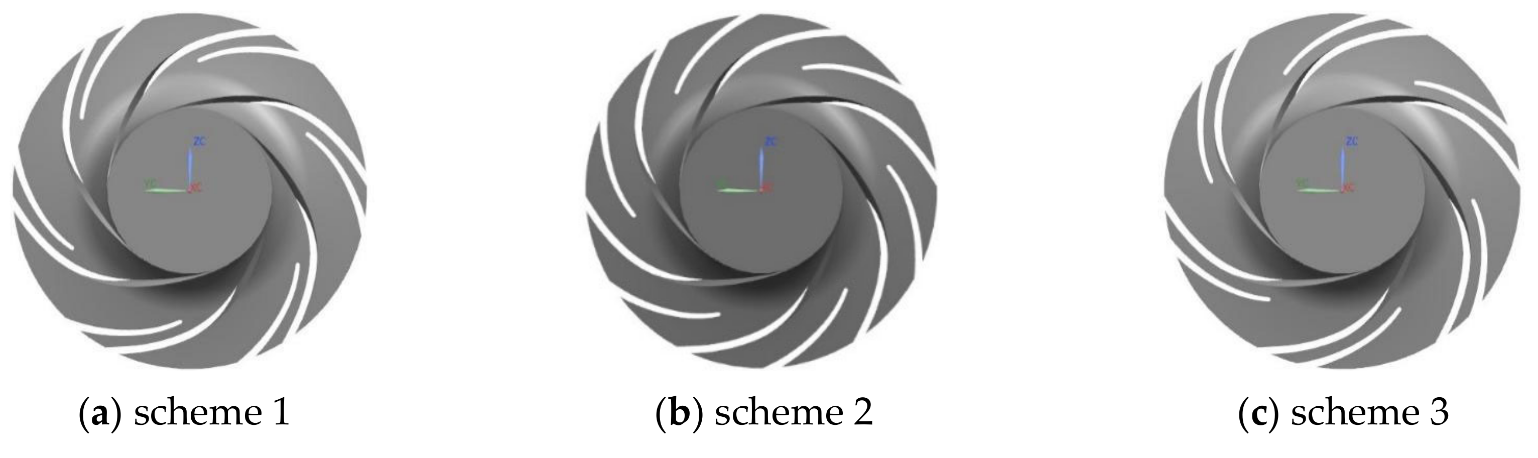
The research object is a volute-type low specific speed centrifugal pump with splitter blades; the design flow rate is 110 m3/h and the design head is 65 m. It is a single-stage centrifugal pump with a rated rotational speed of n = 3000 rev/min, and z = 12 (6 long and 6 short blades), D2 = 215 mm, b2 = 32 mm. Scheme 1: the short blades are arranged along the rotational direction of the impeller, and the angle between the outlets of the long- and short-blade pressure surfaces is 15°. Scheme 2: the short blades are arranged along the rotational direction of the impeller, and the angle between the outlets of the long- and short-blade pressure surfaces is 30°. Scheme 3: the arrangement position of the short blades is along the rotational direction of the impeller, and the outlet angle of the pressure surface of the long and short blades is 45°. The three-dimensional modeling software Pro/E is used for solid modeling and for the assembly of the calculation domains of each scheme. All the water bodies include an inlet section, impeller, volute, and outlet section. In order to enable the fluid to fully develop before entering the impeller and the volute outlet and accurately simulate the flow state of the fluid, the inlet and outlet sections are appropriately extended [24]. Figure 1 shows the schematic diagram of the impeller water body in each scheme.
3.2. Meshing
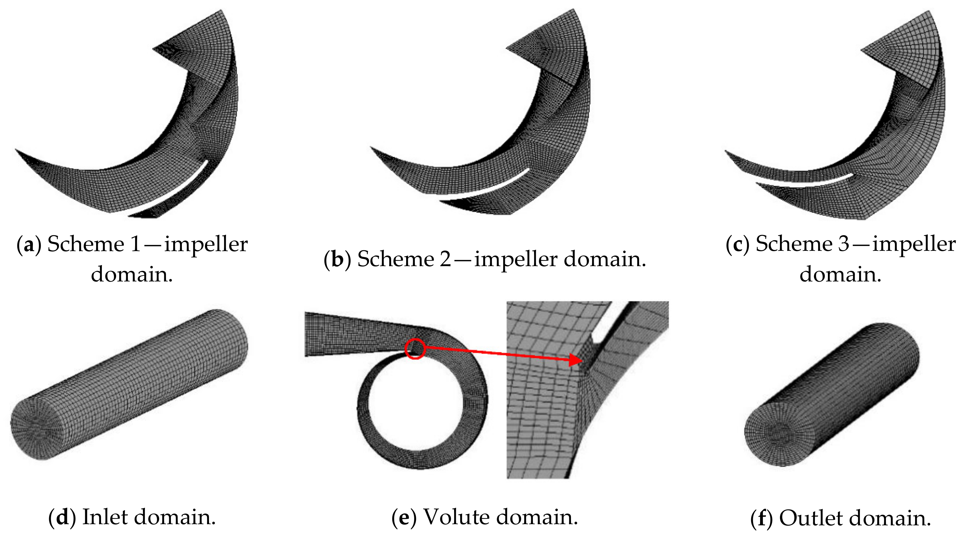
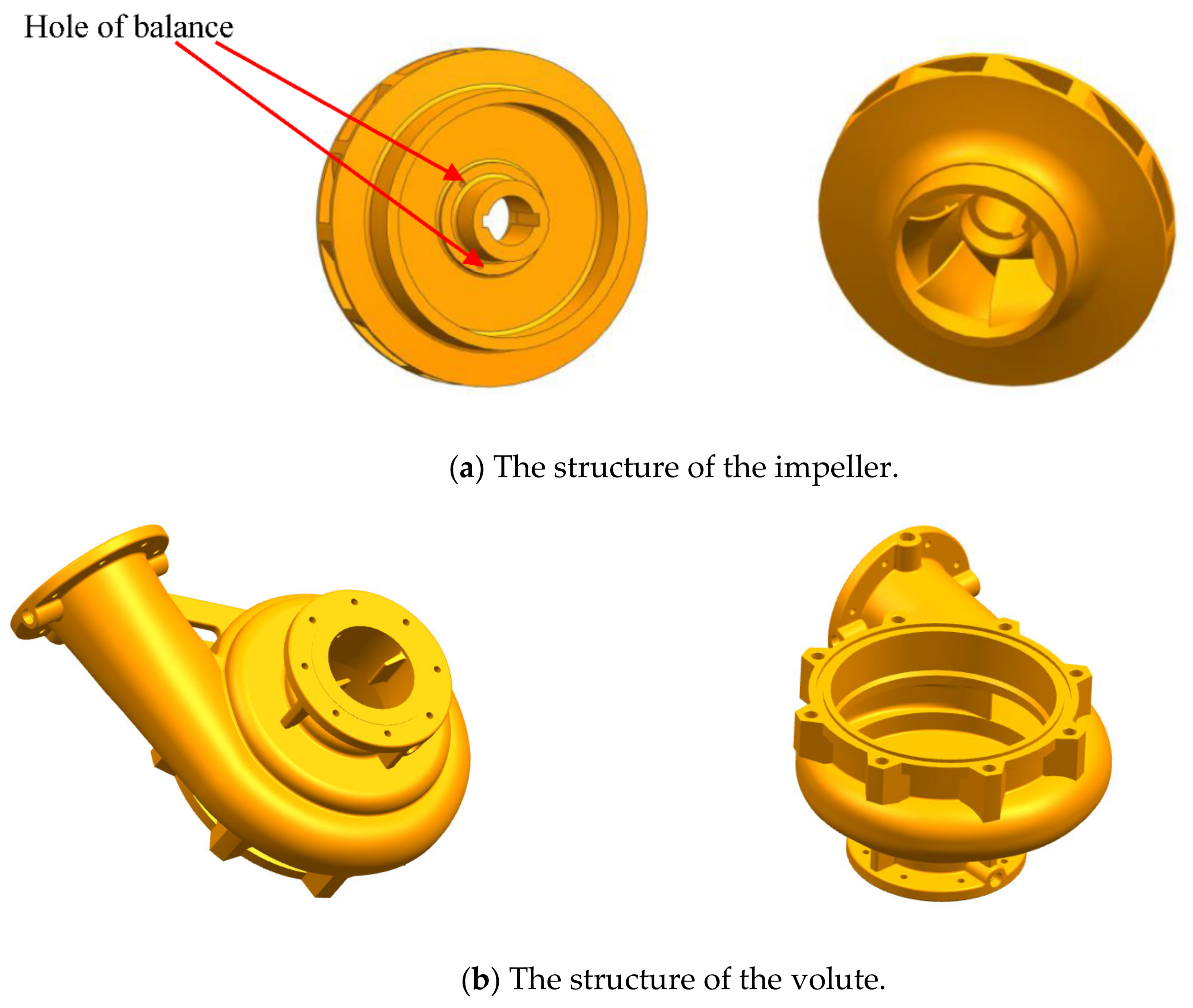
Due to the complexity of the boundary conditions and the governing equations, it is difficult to directly solve the continuous fluid domain. Therefore, discretizing the spatial domain and solving the discretized system of equations can greatly reduce the difficulty of numerical calculation and improve the accuracy of the solution. The basis of discretization is meshing. In this paper, the ANSYS ICEM(ANSYS corporations of American) is used to build the structured mesh in the calculation domain water body. The hexahedral structure grid is generated by topological block mapping. The relationship between the adjacent nodes is clear and the quality is high. It is easy to control the grid details near the wall surface or the complex flow area. The streamline distribution and grid orthogonality are well controlled. Grid details are shown in Figure 2. The structure of impeller and volute are shown in Figure 3.
3.3. Grid Independence Analysis
Grid division is an important pre-processing step for numerical simulation. The quality and number of grids directly affect the accuracy of numerical calculation results. In this paper, based on the finite volume method, meshing is performed in ANSYS ICEM 14.1 (after grid independence analysis, the following number of meshes are finally adopted: 2.5265 million for scheme 1, 2.623 million for scheme 2, and 2.427 million for scheme 3). Steady numerical calculation is performed in ANSYS CFX 14.1.
4. External Characteristics Prediction
4.1. Prediction of Flow-Efficiency Characteristic Curve under Pure Water Conditions
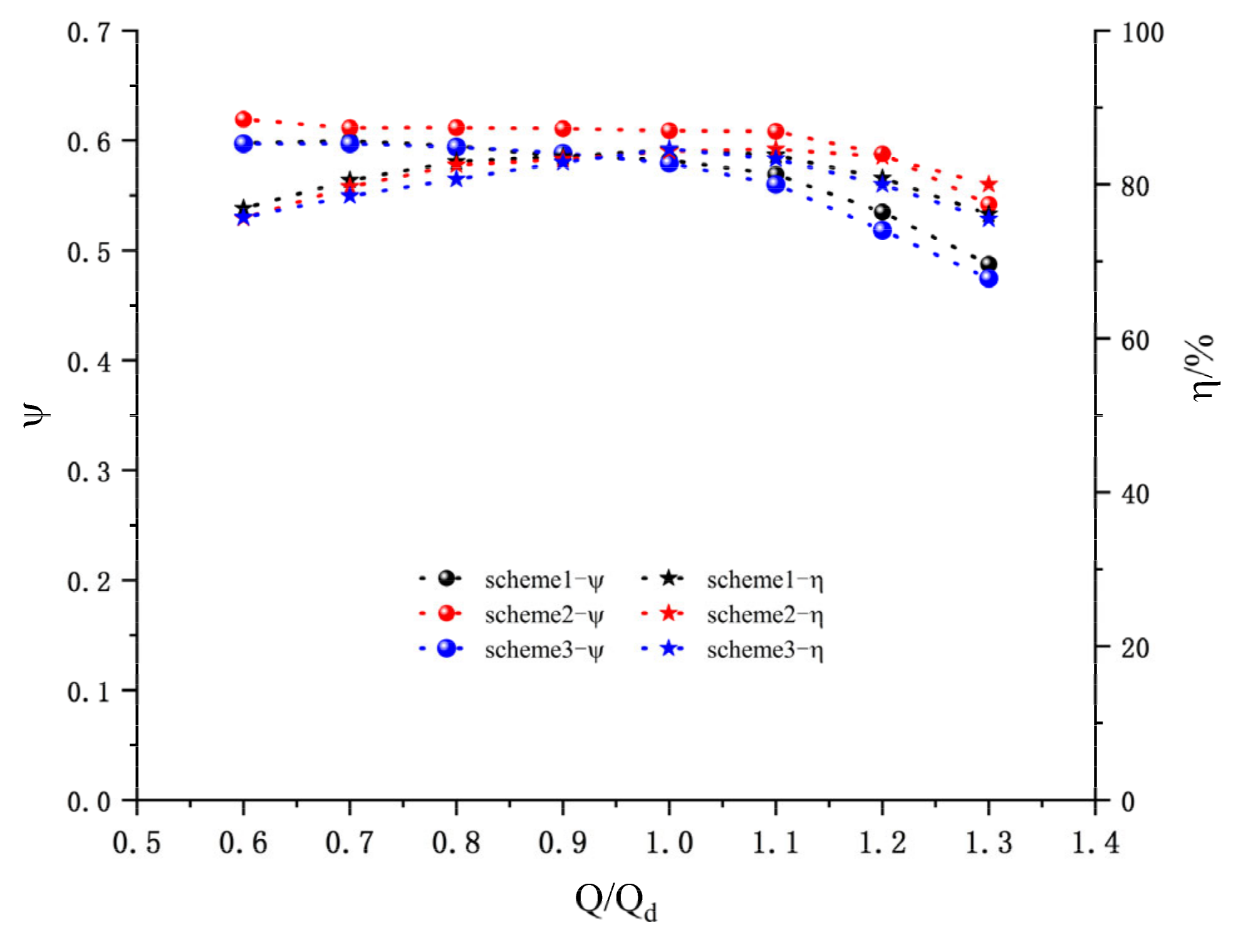
Under the condition that the size of the blade is unchanged in the impeller, the offset method of the short blade is the essential cause of the internal flow difference in each scheme, and the efficiency is the external manifestation of the internal flow change. In order to study and analyze preliminarily the internal flow changes of three different schemes, eight working condition points of the model pump were selected for numerical calculation, which were Q/Qd = 0.6, 0.7, 0.8, 0.9, 1.0, 1.1, 1.2, and 1.3. The flow–efficiency curve and flow–head curve of the model pump in three different schemes are shown in Figure 4.
The non-dimensional head coefficient is defined as:
where H means head and means the peripheral speed of the outlet of the impeller.
The η is defined as:
where H means head, and Q means the flux; M is torque, and ω means the angular velocity of the impeller.
It can be seen from Figure 4 that, under the condition that the length and shape of the blade, the volute and the inlet and outlet of the impeller are unchanged, and the flow–efficiency characteristic curve changes with the change in the layout position of the short blade. In scheme 2, the short blades are arranged between the two long blades, and it can be seen from the efficiency characteristic curve that the optimal working point of the centrifugal pump corresponding to the impeller is shifted to the high-flow operating point (Q/Qd = 1.1), This may be caused by the matching of the throat area of the volute with a too-large impeller vane. This leads to the transition of the optimal working condition from 1.1Qd in scheme 2 to 1.0Qd in schemes 1 and 3. Looking at the entire efficiency characteristic curve, the efficiency at the design point of the three schemes is relatively close. The efficiency characteristic curves of the three schemes are different, which is caused by the difference in the two flow-paths divided by the short blades. Comparing the head characteristic curves of the three schemes, scheme 2 has an obvious hump phenomenon at 0.7Qd, and the presence of the hump will cause an unstable operating point when the pipeline characteristic curve matches the pump performance curve and leads to severe vibration. The heads decrease sharply with the increase in the flow in the range of the large flow (1.0Qd–1.2Qd) of schemes 2 and 3, which shows that the impeller corresponding to this scheme should not run for a long time under the condition of large flow.
4.2. Prediction of the External Characteristics of the Second Scheme and its Experimental Verification
In order to obtain the performance of the hydraulic prototype of the centrifugal pump, the external characteristic was experimentally analyzed, and the accuracy of the numerical simulation was verified by comparing the deviation of the experimental value and the numerical calculation value. Because the number of schemes involved in this article is large, only scheme two is tested by experimental verification. At present, research results show that in the high-efficiency zone (0.6Qd–1.2Qd) of the pump, the predicted value of the external characteristics of the pump is in good agreement with the test value [24]. When CFX calculates the low-flow operating points and the large-flow operating points, the predicted data deviates greatly from the actual situation, so this article only calculates the flow points in the range from 0.6 to 1.2Qd.
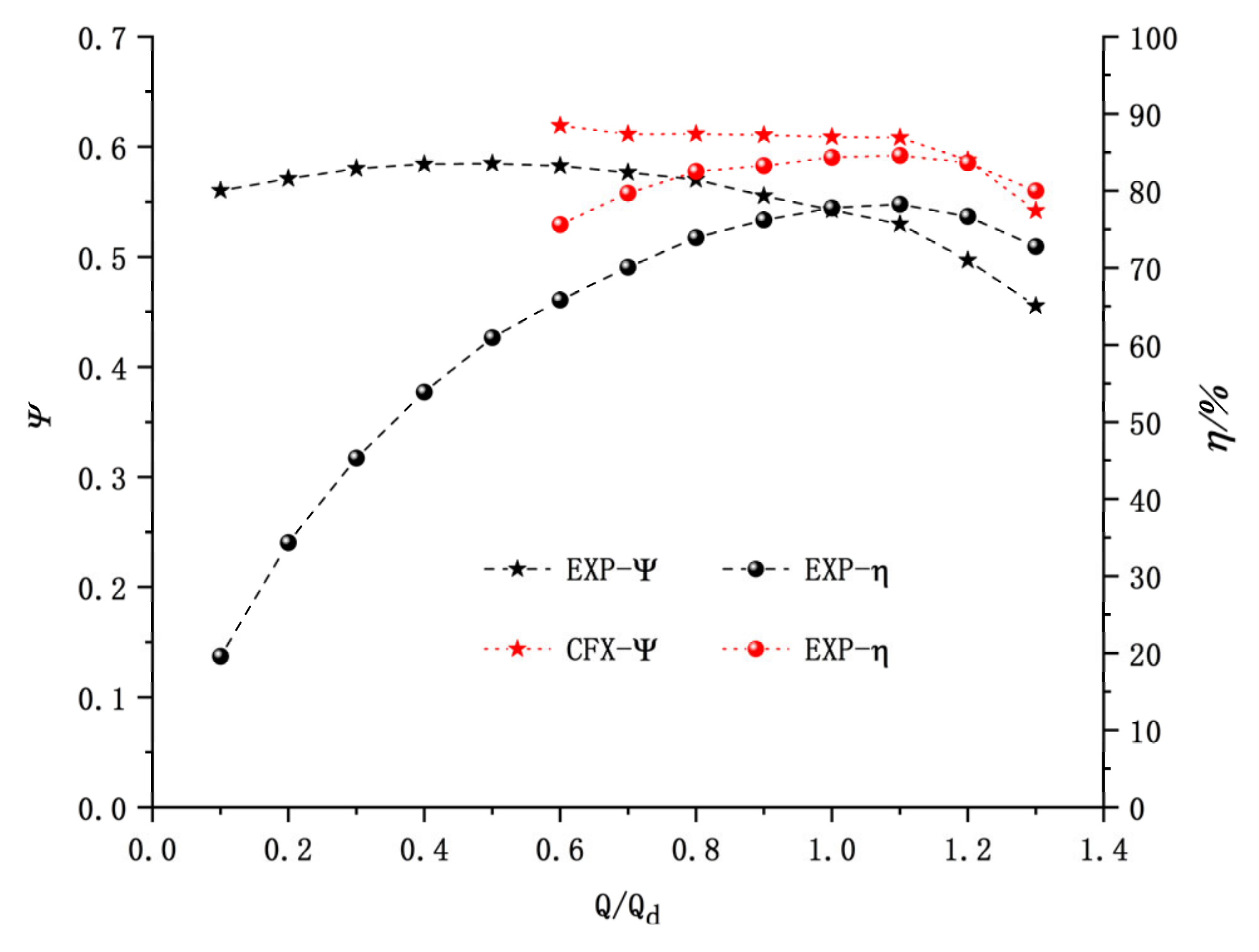
The comparison between the experiment and simulation is shown in Figure 5. It can be seen that, with the increase in the flow rate, the numerical simulation result of the head differs from the experimental value more and more and the simulation values of head and efficiency are higher than the experimental values. The efficiency simulation results are basically the similar as the experimental efficiency curve. The optimal efficiency points are all at 1.1Qd. The simulation efficiency is higher than the experimental efficiency. This is due to the simplification of the real flow field in the numerical calculation and the fact that it did not consider the influence of the balance hole on the internal flow field during the numerical calculation process. The numerical calculation head coefficient curve is higher than the experimental value and the maximum head deviation reaches 7.6% under large flow conditions. The main reason is that there is a certain deviation in predicting the performance of the centrifugal pump by the steady simulation of a single phase. At the same time, according to experience, a larger blade outlet placement angle should be adopted for the low-to-medium specific speed centrifugal pump to increase the head. In order to obtain higher efficiency and avoid a hump, it is necessary select a smaller blade outlet placement angle for this scheme and increase the outer diameter of the impeller to ensure the design head. The disc friction loss is proportional to the 5th power of the impeller diameter. Increasing the outer diameter of the impeller increases the friction loss of the disc inside the impeller. However, the disc loss is not considered in the numerical simulation, and the volume loss of centrifugal pumps with medium and low specific speeds is, in terms of percentage, larger than that with a high specific speed. Therefore, the simulation results are quite different from the experimental results. In general, when the pump is running in the range of (0.6–1.2Qd), the simulation results show little deviation from the experimental results. This further proves that numerical simulation can be an effective means and tool for predicting the energy characteristics of the centrifugal pump and can ensure the accuracy of further analysis.
4.3. Prediction of Flow-Efficiency Characteristic Curve of Gas-Liquid Two-Phase Flow under Design Conditions
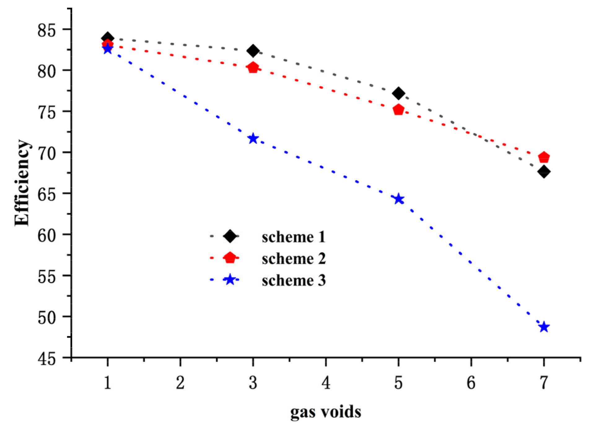
It can be seen from Figure 4 that the efficiencies of the three schemes are almost the same at the design point (1.0Qd), and the CFD numerical calculations are carried out for the 1.0Qd working condition and the inlet gas volume fractions ratio α = 1%, 3%, 5%, 7%. Figure 5 is the efficiency characteristic curve of each scheme under different inlet gas void fraction and the design condition.
It can be seen from Figure 6 that, under the condition that the length and shape of blade, the volute, and the inlet and outlet of the impeller are unchanged, and with the same inlet gas volume fractions, the efficiency changes with the change of offset type of the short blade. For the same model pump, the efficiency decreases with the increase in the inlet gas volume fraction; when the inlet gas volume fraction is 1%, the efficiency change of the model pumps of the three schemes is very small, and this depends on the condition of small inlet gas volume fractions. After the air bubble enters the impeller, it forms fine bubbles under the shearing action of the blade and is directly entrained by the fluid in the impeller and discharged from the impeller. When the inlet gas volume fraction is greater than 1%, with the increase in the inlet gas volume fraction, scheme 4 has the fastest rate of decline in efficiency, scheme 2 is the second, and scheme 1 has the slowest rate of decline in efficiency. The existing literature [12,13,23,25] pointed out that the gas is mainly distributed in the area near the suction surface of the blade and the outlet of the impeller flow channel under the condition of the mixed gas-liquid transportation. On the suction surface of the blade, due to the pressure difference, bubbles always accumulate in the vicinity of the suction surface. The higher the inlet gas volume fraction, the more obvious the gathering phenomenon, due to gas accumulation a serious separation phenomenon occurs, so that the efficiency drops sharply. Among the three schemes, the arrangement of the short blades in the scheme 1 makes the pressure surface of the short blades closest to the suction surface of the long blades. When the inlet gas volume fraction increases, some bubbles on the suction surface of the long blades break down and flow out of the impeller with the liquid under the action of the pressure surface of the short blades. The short blade circumferential arrangement of scheme 3 moves the pressure surface of the short blade away from the suction surface of the long blade. With the increase in the inlet gas volume fraction, the shear effect of the short blade on some bubbles is greatly weakened, and a large number of bubbles gathered in the area near the suction surface of the long blade cannot be discharged out of the impeller in time; the hydraulic loss is increased and the efficiency is significantly reduced. The position of the short blade working surface near the suction surface of the long blade is between schemes 1 and 3, so the efficiency drop rate is also between that of the other two schemes. When the inlet gas volume fraction is 7%, the efficiency of scheme 2 is higher than that of scheme 1. Taking into account Figure 6, this may be due to the large amount of bubbles accumulating on the suction surface of the long blade with the increase in the inlet gas volume fraction. Due to the offset position of the short blade being too close to the suction surface of the long blade, the overflow area of the pressure surface of the short blade and the suction surface of the long blade is too small, and the accumulated bubbles cannot be discharged in a large amount.
5. Internal Flow Field Analysis
5.1. Velocity Streamline Diagram of Impeller Flow Field Mid-Section under Different Pure Water Working Conditions
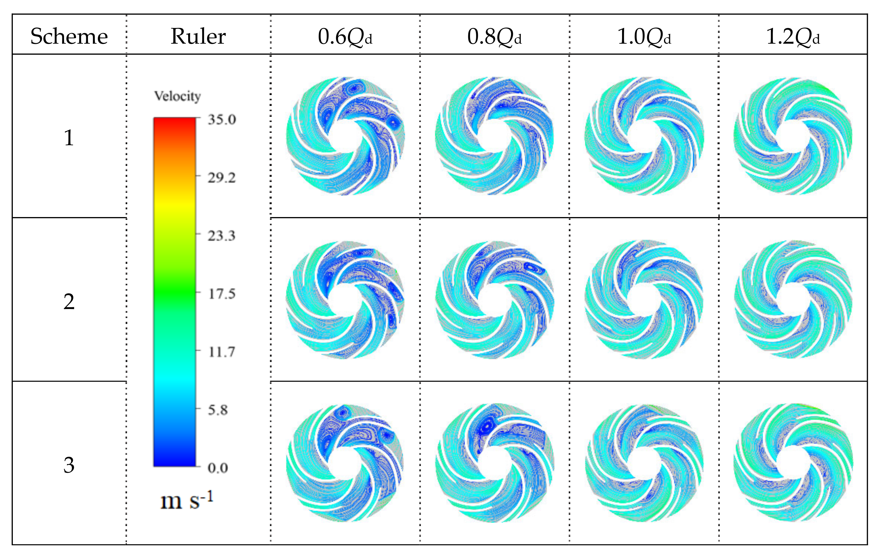
Figure 7 shows the velocity flow diagram of the impeller cross-section under different pure water conditions. Under different flow conditions, the velocity of the suction surface of the long blade is greater than that of the pressure surface. Under the flow conditions of 1.0Qd and 1.2Qd, the flow state in the impeller flow-path is relatively stable, and the relative velocity of the fluid basically flows along the direction of the blade surface. Under the 1.0Qd working condition, only a slight backflow phenomenon occurs in the area near the inlet of the short blade and the area near the working surface of the short blade. As the flow rate decreases to 0.8Qd, an obvious backflow phenomenon occurs in the impeller and in part of the flow-path begin to appear axial vortices rotating in the opposite direction to the impeller. The generation of axial vortices causes the impeller flow-path to be blocked and fluid energy loss in the form of a vortex. The final performance is a decrease in efficiency. Only one of the three schemes did not produce an axial vortex under 0.8Qd, so the efficiency of scheme 1 is higher than the other two schemes under 0.8Qd, and the jet-wake phenomenon occurs at the impeller outlet. With the further decrease in the flow (0.6Qd), the flow separation on the suction surface of the long blade is intensified, the number of axial vortices in the impeller flow-path gradually increases, and the size continues to increase. The axial vortex area expands to multiple impeller flow-path areas, which seriously blocks the impeller flow-path, and the jet-wake phenomenon at the impeller outlet becomes more obvious.
5.2. Turbulent Kinetic Energy Distribution Cloud Diagram of Impeller Flow Field Mid-Section under Different Pure Water Working Conditions
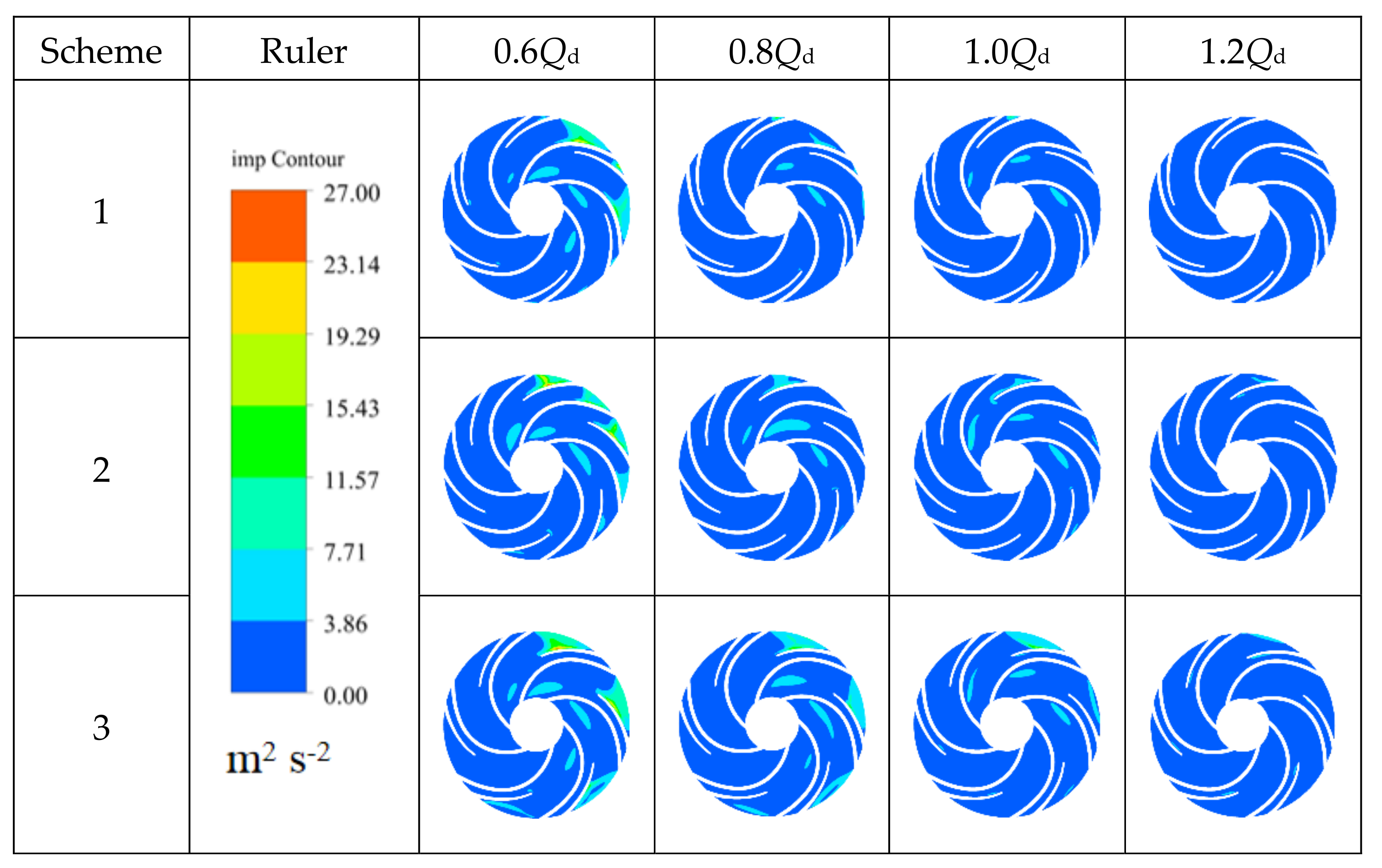
Figure 8 shows the distribution of the turbulent kinetic energy of the impeller mid-section under different pure water conditions.
From the above figure, the turbulent kinetic energy in the impeller gradually decreases with the increase in the flow rate. Under small flow working conditions (0.6Qd), the turbulent kinetic energy is mainly distributed in some part of the flow-path near the impeller outlet. Combined with that deduced from Figure 6, this may be caused by the flow turbulence because of the severe jet-wake phenomenon at the impeller outlet. When the working conditions are within the range of 0.8–1.2Qd, the distribution area of turbulent kinetic energy in the impeller flow-path is small, which indicates that the ideal operating flow range of the three schemes is 0.8Qd–1.2Qd, especially under the large flow working conditions (1.2Qd). The range of turbulent kinetic energy is basically within 3.86, which is consistent with the engineering concept that the pump is expected to work at a relatively large flow rate. Combining this with the flow-head characteristic curve of Figure 4, it can be seen that if the pump works under pure water conditions, the short blade axial position of the scheme 2 is more reasonable. Comparing the turbulent kinetic energy of different impellers under the same flow conditions, the distribution and value of the turbulent kinetic energy of the three schemes are different, and the only variation among the three schemes is the difference in the axial offset position of the short blades, which shows that the short blades’ axial offset is the root cause of the difference in the turbulent kinetic energy.
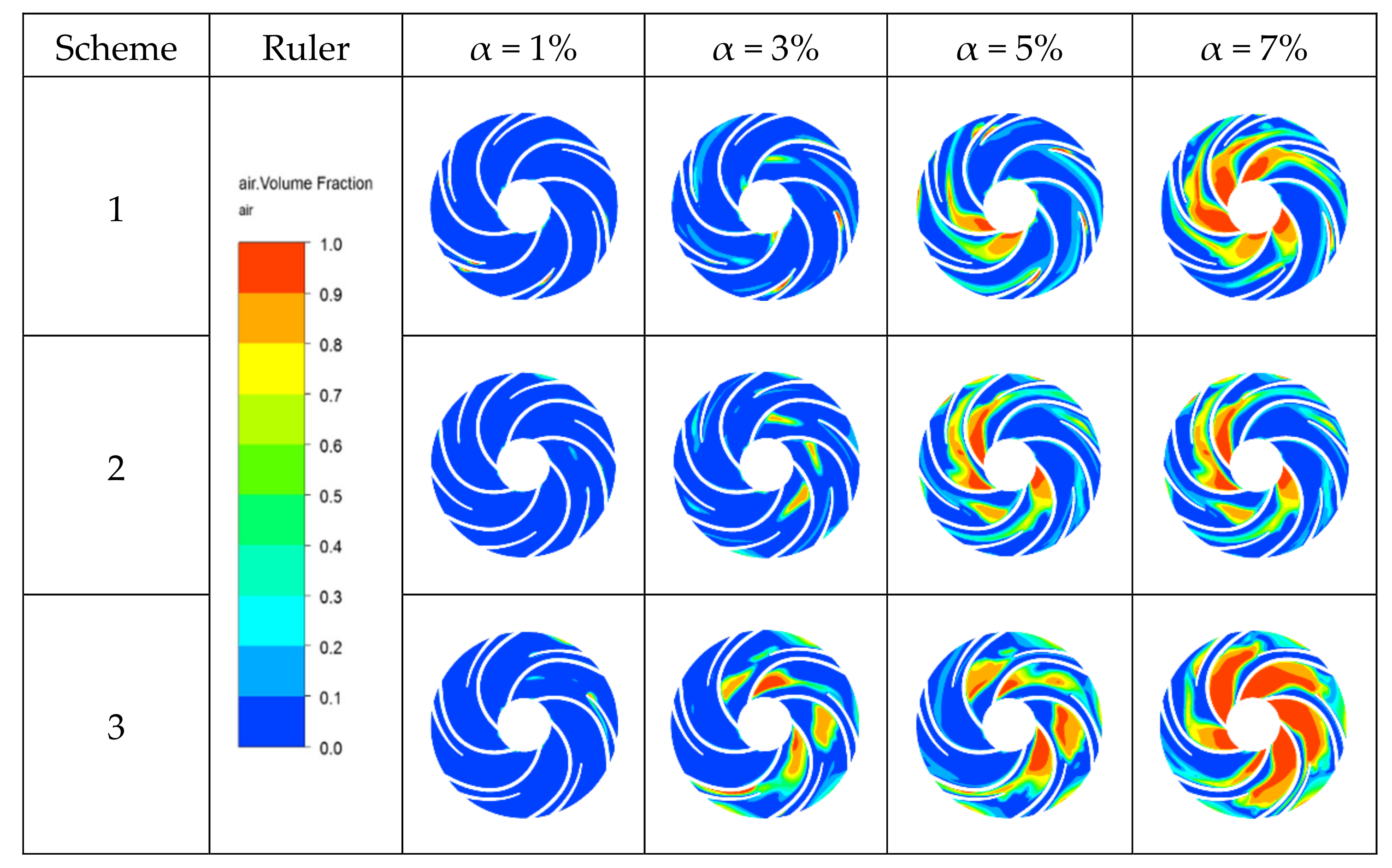
5.3. The Gas Phase Distribution in the Mid-Section of the Impeller of Each Scheme with Different Inlet Gas Volume Fractions under the Design Conditions
Figure 9 shows the gas phase distribution cloud diagram in the impeller of each scheme under different inlet gas volume fractions and design conditions. It can be seen from the figure that, under the same inlet gas volume fraction, the distributions of the gas volume fractions in different impellers are different. When the inlet gas volume fractions are within 5%, the distribution of the gas volume fraction increases with the distance between the arrangement position of the short blade and the suction surface of the long blade. When the inlet gas volume fraction reaches 7%, the gas volume fraction in the impeller of scheme 1 is more than that of scheme 2. This may be because the short blade is close to the suction surface of the long blade, and the short blade occupies part of the flow-path near the suction surface of the long blade, which causes bubbles to gather in this area for a long time. For the same impeller, as the inlet gas volume fraction increases, the gas content in the impeller gradually increases. The gas is mainly distributed on the long and short blade suction surfaces and the outlet of the impeller flow-path, indicating that the gas is mainly distributed in the suction surfaces of the impeller flow-path. Then, the gas gradually move toward the outlet of the impeller flow-path along the suction surface side of the blade. It can be found from the figure that when the inlet gas volume fraction reaches 3%, a slight gas-liquid separation phenomenon begins to occur at the outlet of the impeller flow-path. The gas-liquid separation phenomenon becomes more and more obvious as the inlet gas volume fraction continues to increase. When the inlet gas volume fraction is 7%, the gas-liquid separation phenomenon is the most obvious. The gas-liquid separation phenomenon of scheme 2 is obviously stronger than that of scheme 1, but schemes 1 and 2 are mainly based on the phenomenon of gas-liquid coexistence. However, scheme 3 develops mainly the gas phase, which also better explains why the efficiency of scheme 3 decreases suddenly and the efficiency of scheme 1 is worse than scheme 2 in Figure 4 when the inlet gas volume fraction is 7%.
5.4. Liquid Velocity Streamline Diagram in the Cross-Section of Impeller under Different Working Conditions
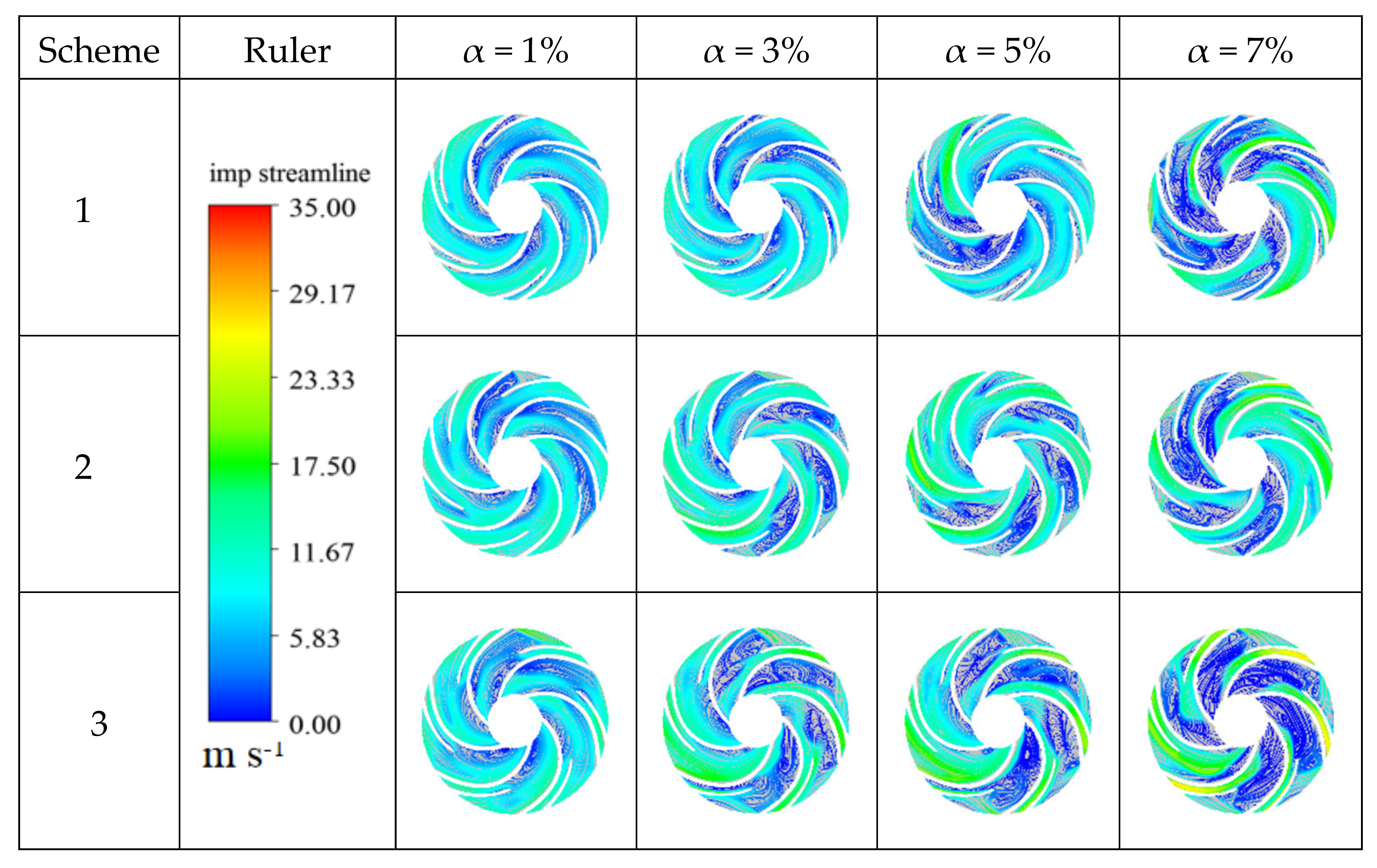
Figure 10 is the liquid velocity streamline diagram of the impeller cross-section under different schemes and different inflow gas volume fractions conditions. It can be seen that, for the same impeller, the liquid phase velocity streamline becomes more and more uneven with the increase in the inflow gas volume fraction. Under the condition of the same inflow gas volume fraction, the liquid velocity in a cross-section of the impeller in each scheme shows great differences. Under the condition of a small inflow gas volume fraction (α = 1%), the liquid phase flow in each flow-path of the impeller is relatively regular. The relative velocity of the liquid phase is basically along the suction surface and the pressure surface of the blade, and only slight backflow phenomenon occurs in some of the flow-paths. When the inflow gas volume fractions are 3% and 5%, the flow separation of the long blade suction surface is significantly increased and accompanied by an axial vortex formed in the impeller flow-path. This axial vortex area increases sequentially in schemes 1, 2, and 3. The number and size of the axial vortices in schemes 2 and 3 are significantly higher than those in scheme 1, and the flow blockage is more serious. The impeller flow-path blockage of scheme 3 is more serious, which shows that the axial vortex and the strength of the flow separation in the impeller flow-path are related to the distance between the circumferential position of the short blade and the suction surface of the long blade. When the inflow gas volume fraction increases to 7%, the axial vortex of the impeller cross-section in scheme 1 is stronger than that in scheme 2, resulting in the short blade flow-path of scheme 1 being basically in a turbulent flow area, and the function of the short blade work is greatly reduced. The-impeller flow-path is blocked in a large area in scheme 3, which is consistent with the hydraulic efficiency of scheme 1 being lower than that of scheme 2 and higher than that of scheme 3, when the inlet gas volume fraction corresponding to Figure 5 is 7%.
6. Conclusions
In this paper, the following conclusions are obtained by the numerical simulation of the internal flow characteristics for a low specific speed centrifugal pump with a short blade arrangement under the design conditions in the gas-liquid mixed transportation state.
- Under pure water conditions, the different circumferential arrangements of short blades can adjust the position of the optimal working point. The reasonable circumferential arrangement of short blades can optimize the overall performance of the pump. In addition, the reasonable circumferential arrangement of the short blades can eliminate the hump of the centrifugal pump under small flow conditions.
- Under the design conditions in the gas-liquid mixed transportation state, when the circumferential arrangement position of the short blades is close to the suction surface of the long blade, some of the bubbles on the suction surface of the long blade can be broken by the pressure of the short blade pressure surface and by the flow coming out of the impeller with the liquid, which improves the flow field in the impeller.
- Air bubbles gather on the suction surface of the blade and move along the suction surface to the outlet of the impeller. The offset position of the short blade is close to the suction surface of the long blade, which helps to improve the flow pattern in the impeller under the condition of small inlet gas volume fractions. When the inlet gas volume fraction reaches 7%, a large number of bubbles in the impeller flow-path accumulate, so that the effective flow area of the original liquid phase is sharply reduced and the head also drops, which shows that the circumferential offset of the short blade to the suction surface of the long blade should have a reasonable range.
Author Contributions
Simulation, B.W. and H.Z.; methodology, B.W.; software, C.W.; formal analysis, C.W.; writing—original draft preparation, B.W. and F.D.; writing—review and editing, H.Z. and Q.S.; funding acquisition, Q.S. All authors have read and agreed to the published version of the manuscript.
Funding
This research was funded by the National Key R&D Program of China (2018YFC0810505) and the National Natural Science Foundation of China (51976079, 51779107).
Conflicts of Interest
The authors declare no conflict of interest.
References
- Cui, Q.L.; Si, Q.R.; Bois, G.; Yuan, S.Q.; Yuan, J.P. Investigation on gas-liquid two-phase flow centrifugal pump performances for different rotational speeds. In IOP Conference Series: Earth and Environmental Science; IOP Publishing: Bristol, UK, 2019; Volume 240, p. 032016. [Google Scholar]
- Yu, Z.Y.; Zhu, B.S.; Cao, S.L.; Wang, G.Y. Application of two-fluid model in the unsteady flow simulation for a multiphase rotodynamic pump. Mater. Sci. Eng. 2013, 52, 1–8. [Google Scholar] [CrossRef]
- Minemura, K.; Uchiyama, T. Three-Dimensional Calculation of Air-Water Two-Phase Flow in Centrifugal Pump Impeller Based on a Bubbly Flow Model. Trans. Jpn. Soc. Mech. Eng. 1989, 55, 4. [Google Scholar] [CrossRef]
- Johann, F.G. Centrifugal Pumps; Springer: Berlin/Heidelberg, Germany, 2008. [Google Scholar]
- Verde, W.M.; Biazussi, J.L.; Sassim, N.A.; Bannwart, A.C. Experimental study of gas-liquid two-phase flow patterns within centrifugal pumps impellers. Exp. Therm. Fluid Sci. 2017, 85, 37–51. [Google Scholar] [CrossRef]
- Si, Q.; Cui, Q.; Zhang, K.; Yuan, J.; Bois, G. Investigation on centrifugal pump performance degradation under air-water inlet two-phase flow conditions. Houille Blanche 2018, 3, 41–48. [Google Scholar] [CrossRef] [Green Version]
- Si, Q.; Bois, G.; Jiang, Q.; He, W.; Ali, A.; Yuan, S. Investigation on the handling ability of centrifugal pumps under air-water two-phase inflow, model and experimental validation. Energies 2018, 11, 3048. [Google Scholar] [CrossRef] [Green Version]
- Pineda, H.; Biazussi, J.; López, F.; Oliveira, B.; Carvalho, R.D.; Bannwart, A.C.; Ratkovich, N. Phase distribution analysis in an Electrical Submersible Pump(ESP) inlet handling water—Air two-phase flow using Computational Fluid Dynamics (CFD). J. Pet. Sci. Eng. 2016, 139, 49–61. [Google Scholar] [CrossRef]
- Lu, J.; Xi, G.; Qi, D. Numerical study of gas-liquid two-phase three-dimensional flow in centrifugal pump impeller. J. Eng. Thermophys. 2003, 0253-231X, 237–240. [Google Scholar]
- Poullikkas, A. Compressibility and condensation effects when pumping gas–liquid mixtures. Fluid Dyn. Res. 1999, 25, 57–62. [Google Scholar] [CrossRef]
- Patel, B.R. Investigations into the Two-Phase Flow Behavior of Centrifugal Pumps. Proc. Polyph. Flow Turbomach. ASME 1978, 124, 79–100. [Google Scholar]
- Yuan, J.; Zhang, K.; Si, Q.; Zhou, B.; Tang, Y.; Jin, Z. Numerical study on gas-liquid two-phase flow of centrifugal pump based on heterogeneous flow model. J. Agric. Mach. 2017, 48, 89–95. [Google Scholar]
- Pan, B.; Wang, W.; Jiang, W. Numerical analysis of gas-liquid two-phase flow in centrifugal pump. Petrochem. Ind. Appl. 2011, 30, 101–104. [Google Scholar]
- An, M.; Liu, X.; Huang, C.; Ke, Q.; Zeng, Z. Research on the influence of splitter blades and their offset design on the performance of centrifugal pumps. China Rural Water Hydropower 2016, 134, 125–128. [Google Scholar]
- Li, G.; Wang, Y.; Lv, X.; Li, W. Flow mechanism and simulation analysis of centrifugal pump with offset splitter blades. J. Northeast Agric. Univ. 2011, 42, 4. [Google Scholar]
- Xie, R.; Hai, Y.; Wang, X. The circumferential position design of the splitter blades and its influence on the internal flow of the centrifugal impeller. Gas Turbine Technol. 2009, 22, 37–41. [Google Scholar]
- Liao, J.; Zhang, X.; Zhang, W.; Liao, G. The effect of splitter blades on solid-liquid two-phase flow in centrifugal pumps. Yangtze River People 2017, 48, 79–82. [Google Scholar]
- Yan, S.; Luo, X.; Feng, J.; Zhu, G.; Zhang, L.; Chen, S. The effect of gas content on the performance of gas-liquid two-phase flow centrifugal pumps. Res. Prog. Hydrodyn. 2019, 34, 353–360. [Google Scholar]
- Chen, C. Theory and Design of Two-Phase Flow Pump; Weapon Industry Press: Beijing, China, 1994. [Google Scholar]
- Zhang, H.; Yang, C.; Yang, D.; Wang, W.; Yang, C.; Qi, M. Investigation on the stall inception circumferential position and stall process behavior in a centrifugal compressor with volute. J. Eng. Gas Turbines Power 2018, 141, 021030. [Google Scholar] [CrossRef]
- Bardelli, M.; Cravero, C.; Marini, M.; Marsano, D.; Milingi, O. Numerical Investigation of Impeller-Vaned Diffuser Interaction in a Centrifugal Compressor. Appl. Sci. 2019, 9, 1619. [Google Scholar] [CrossRef] [Green Version]
- Fu, Q.; Xi, Y.; Zhu, R.; Yuan, S.; Wang, X. Unsteady analysis of the influence of gas content on AP1000 nuclear main pump. Vib. Shock 2015, 34, 132–136. [Google Scholar]
- Su, Y.; Wang, Y.; Duan, X. Experimental study on centrifugal pump cavitation. J. Agric. Mach. 2010, 41, 77–80. [Google Scholar]
- Shi, W.; Xu, L.; Wang, C.; Lu, W.; Zhou, L. Unsteady numerical calculation and analysis in volute centrifugal pump. J. Agric. Mach. 2014, 45, 49–53, 60. [Google Scholar]
- Si, Q.; He, W.; Cui, Q. Experimental and Numerical Study on Flow Induced Characteristics of Centrifugal Pump under Air-Water Bubble Inflow. In Proceedings of the Symposium on Hydraulic Machinery and Systems, Kyoto, Japan, 17–21 September 2018. [Google Scholar]
Figure 1.
Impeller domains of the flow field calculation.

Figure 2.
Mesh of the centrifugal pump.

Figure 3.
The structure of the impeller and volute of scheme 2.

Figure 4.
External characteristics under different schemes.

Figure 5.
Comparison of the external characteristics. EXP stands for experimental data and CFX represents numerical simulation data.
Figure 5.
Comparison of the external characteristics. EXP stands for experimental data and CFX represents numerical simulation data.

Figure 6.
The efficiency of each scheme under different inlet gas volume fractions.

Figure 7.
Velocity streamline diagram of a cross-section of the impeller flow field under different flows in pure water conditions.
Figure 7.
Velocity streamline diagram of a cross-section of the impeller flow field under different flows in pure water conditions.

Figure 8.
Turbulent kinetic energy distribution cloud map in a cross-section of the impeller under different flow rates in pure water conditions.
Figure 8.
Turbulent kinetic energy distribution cloud map in a cross-section of the impeller under different flow rates in pure water conditions.

Figure 9.
Gas distribution cloud map of the cross-section of the impeller flow field under different flow rates in water with various gas volume fractions.
Figure 9.
Gas distribution cloud map of the cross-section of the impeller flow field under different flow rates in water with various gas volume fractions.

Figure 10.
Liquid phase velocity streamline diagram of the impeller flow field cross-section for each inflow gas volume fraction of each scheme under the design conditions.
Figure 10.
Liquid phase velocity streamline diagram of the impeller flow field cross-section for each inflow gas volume fraction of each scheme under the design conditions.

Publisher’s Note: MDPI stays neutral with regard to jurisdictional claims in published maps and institutional affiliations. |
© 2020 by the authors. Licensee MDPI, Basel, Switzerland. This article is an open access article distributed under the terms and conditions of the Creative Commons Attribution (CC BY) license (http://creativecommons.org/licenses/by/4.0/).
Share and Cite
MDPI and ACS Style
Wang, B.; Zhang, H.; Deng, F.; Wang, C.; Si, Q. Effect of Short Blade Circumferential Position Arrangement on Gas-Liquid Two-Phase Flow Performance of Centrifugal Pump. Processes 2020, 8, 1317. https://doi.org/10.3390/pr8101317
AMA Style
Wang B, Zhang H, Deng F, Wang C, Si Q. Effect of Short Blade Circumferential Position Arrangement on Gas-Liquid Two-Phase Flow Performance of Centrifugal Pump. Processes. 2020; 8(10):1317. https://doi.org/10.3390/pr8101317
Chicago/Turabian StyleWang, Biaobiao, Haoyang Zhang, Fanjie Deng, Chenguang Wang, and Qiaorui Si. 2020. "Effect of Short Blade Circumferential Position Arrangement on Gas-Liquid Two-Phase Flow Performance of Centrifugal Pump" Processes 8, no. 10: 1317. https://doi.org/10.3390/pr8101317
Note that from the first issue of 2016, this journal uses article numbers instead of page numbers. See further details here.