


Thermal Methane Cracking on Molten Metal: Kinetics Modeling for Pilot Reactor Design
by
 and
and
Emma Palo
1, 
Vittoria Cosentino
1,*,
Gaetano Iaquaniello
1,
Vincenzo Piemonte
2 and
Emmanuel Busillo
3 1
NextChem Spa, Via di Vannina 88/94, 00156 Rome, Italy
2
Department of Science and Technology for the Sustainable Development and One Health, University Campus Bio-Medico di Roma, Via Álvaro del Portillo 21, 00128 Rome, Italy
3
Department of Chemical Engineering, University La Sapienza di Roma, Via Eudossiana 18, 00184 Rome, Italy
*
Author to whom correspondence should be addressed.
Processes 2023, 11(5), 1537; https://doi.org/10.3390/pr11051537
Submission received: 30 March 2023
/
Revised: 8 May 2023
/
Accepted: 15 May 2023
/
Published: 17 May 2023
(This article belongs to the Special Issue Industrial Chemistry Reaction: Kinetics, Mass Transfer and Industrial Reactor Design (II))
Abstract
:Up to 80% of hydrogen production is currently carried out through CO2 emission-intensive natural gas reforming and coal gasification. Water-splitting electrolysis using renewable energy (green H2) is the only process that does not emit greenhouses gases, but it is a quite energy-demanding process. To significantly contribute to the clean energy transition, it is critical that low-carbon hydrogen production routes that can replace current production methods and can expand production capacity to meet new demands are developed. A new path, alternative to steam reforming coupled with CCS (blue H2) that is based on methane cracking, in which H2 production is associated with solid carbon instead of CO2 (turquoise H2), has received increasing attention recent years. The reaction takes place inside the liquid bath, a molten metal reactor. The aim of this article is to model the main kinetic mechanisms involved in the methane cracking reaction with molten metals. The model developed was validated using experimental data produced by the University of La Sapienza. Finally, such a model was used to scale up the reactor architecture.
1. Introduction
The European Union aims to reach climate neutrality by the 2050, which means that Europe needs to be carbon neutral years before. Clean energy technology deployment must accelerate rapidly to meet climate goals [1]. Today, hydrogen is mainly produced from fossil fuels, resulting in close to 900 Mt of CO2 emissions per year. Approximately 48% of H2 comes from natural gas through the steam reforming process, 30% comes from naphtha/oil reforming in the chemical industry and 18% comes from coal gasification. Only the remaining 4% is generated by water electrolysis, allowing a CO2-free process, only if the electricity comes from renewable sources [2,3].
Therefore, in order to significantly contribute to the clean energy transition, it is critical to develop low-carbon hydrogen production routes. Natural gas reforming with carbon capture and storage (CCS) (Blue H2) and electrolysis (Green H2) are today the two main alternatives [1]. However, a new path based on methane pyrolysis (Turquoise H2) has garnered increasing interest in recent years and may represent an interesting option during the transition to a long-term sustainable society [4].
Methane cracking is based on the splitting of methane into hydrogen and carbon, without any associated CO2 emissions [5]. The main reaction is endothermic and characterized by strong kinetic limitations due to a high activation energy, which is between 356 and 452 kJ/mol [2].
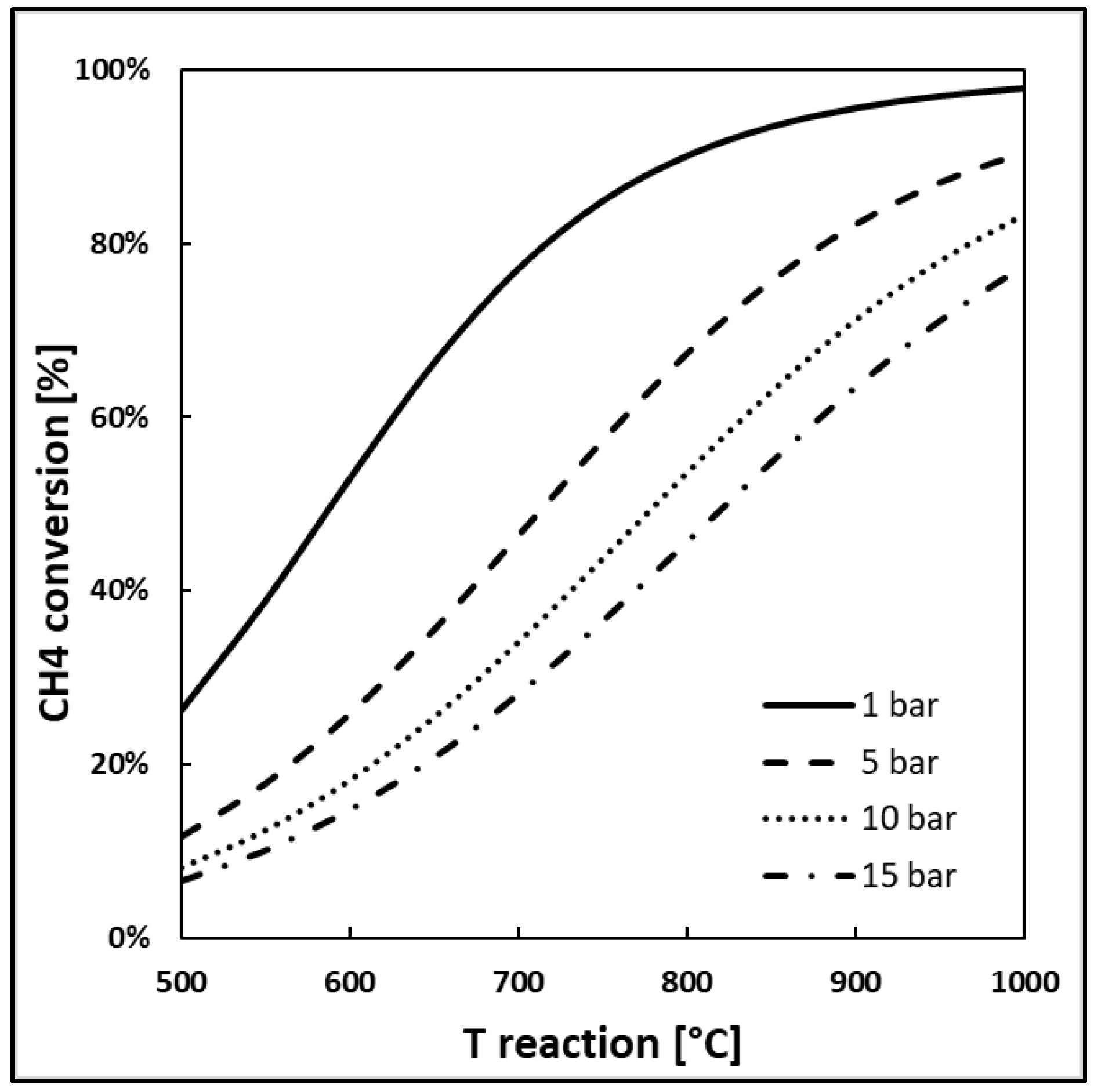
The reaction can occur in a thermal, catalytic and combined process. Thermal cracking occurs theoretically above 300 °C; however, only around 1000 °C can a reasonable high conversion be reached [2]. Figure 1 shows the CH4 conversion calculated at equilibrium at different pressures and temperatures using Aspen Plus software v11 by Aspen Tech, which presents the same trend reported in the literature [6].
Catalyst addition enables a reduction in the activation energy to the range of 96.1–236 kJ/mol, according to the catalyst type. Different kinds of catalysts are studied in the literature for this application. Solid catalysts have been used to lower the activation energy of the reaction and to increase the reaction rate at moderate temperatures (below 1000 °C). Such catalysts are either metallic catalysts (Ni, Pd, Pt, Fe, Ni-Pd, etc.) usually supported on metal oxides (Al2O3, MgO, etc.), or carbonaceous catalysts (activated char, carbon black, etc.) [2]. The active metals used in conventional methane cracking can be based on transition metals (Ni > Co > Fe) and noble metals (Pt, Pd), with catalytic activity, however, impacted by coking in time on stream tests, due to the blockage of active sites [7]. Ni-based catalysts are the most active and stable at temperatures between 500 and 700 °C, but they rapidly deactivate with increasing temperatures. Moreover, Ni is toxic, therefore any downstream use of a carbon product is enabled if purification is carried out. Fe-based catalysts are cheaper and use a nontoxic metal, but require higher temperatures (700–900 °C) [8]. Carbonaceous catalysts, such as activated char/biochar/coal char and carbon black, have also been reported for methane cracking. Their main benefits are a lower cost, no contamination of by-products carbon and more resistance to sulfur [9].
One of the main concerns regarding catalytic cracking is the clogging of the catalyst formed by the carbon, which usually therefore needs to be regenerated in steam or air. Regeneration is not always simple and for some metals, such as Ni, it is almost impossible to recover the initial activity of the catalyst. Furthermore, even if carbonaceous catalysts do not theoretically necessitate regeneration, their catalytic activity also drops after a few hours of operation [2].
To conclude, regardless of whether methane cracking is catalytic or not, the main problem is the cumulative deposition of coke, which can plug not only the catalyst, but the reactor itself after a few hours of operation [10].
A possible solution is to carry out the reaction in a molten media, such as in liquid bubble column reactors [11,12]. The feed gas is then injected at the bottom of the reactor, which rises as bubbles through the molten metal. In this way, the carbon can be easily separated in continuous operation since the low-density solid carbon floats on the surface of the liquid, preventing carbon accumulation and the blockage of the reactor [2,12,13]. This solution still represents a challenge regarding its applicability on an industrial scale [14].
Molten media present other advantages, such as their ability to improve heat transfer and thermal inertia due to their heat capacity, to increase the residence time due to the liquid viscosity, to enable efficient heating using renewable electricity and thus replace fossil fuel combustion, and the liquid phase may catalyze the reaction [2,12].
Molten media can be both molten salts and molten metals. Molten metals show a higher performance in terms of catalytic activity than molten salts. In particular, Ni, Pd, Pt, Co and Fe have a high catalytic behavior, while In, Ga, Sn, Pb and Bi are considered inert metals with low catalytic activity, even if their combination could highly modify the alloy activity and bring unexpected results, exceeding the performance of active metal alloys [2,13]. Furthermore, molten metals should offer isothermal conditions during cracking, and generally have high thermal conductivities. Therefore, they can homogenize the temperature, enhancing methane decomposition [2,12].
Starting from all the above considerations, it was decided that the thermal methane cracking using molten tin in a liquid bubble reactor would be analyzed. The first patent on molten methane cracking was proposed by Tyrer in 1931, although this solution was not considered until the 1990s [15]. Among the studies of the last twenty years, Steinberg was one of the first to propose a bubble reactor configuration with a tin/copper molten metal bath to promote heat transfer and carbon separation [16]. Serban et al. conducted experiments using a stainless-steel feed tube or a porous metal sparger, injecting the methane gas from the top into liquid tin or lead, with or without a packed bed of SiC; they achieved a conversion of 57% at 750 °C with a packed bed/tin combination and a porous metal sparger [17]. Geißler et al. studied the thermo-chemical modeling of hydrogen production in a liquid metal bubble column reactor filled with tin, using a packed bed and a methane volume flow rate of 50 mL/min, obtaining a maximum hydrogen yield of 30% at 1000 °C [18]. Catalan et al. proposed a model that takes into account the coupling between kinetics and hydrodynamics for thermal and catalytic cracking. The model combines a drift flux correlation for gas hold-up, one of the most critical parameters in this type of application, and a thermodynamically consistent kinetic model of methane decomposition [13]. Subsequently, this first model was improved so that the interfacial area and gas hold-up can be calculated as a function of the operating conditions in the reactor, with no assumptions about the bubble size [19].
The purpose of this work is to analyze in particular the kinetic mechanisms involved in the reaction in the molten media. The main factors to be considered are the high temperature, high residence time in the liquid phase and the diameter of the bubbles along the reactor. A simplified mathematical model to predict methane conversion is developed and solved for both lab-scale and industrial-scale reactors. The results of the first case are compared with experimental data produced by the Department of Chemical Engineering University of La Sapienza in Rome, in order to carry out a first validation of the approach used.
This work is connected to the evaluations of the process scheme and reactor design described in two applied patent applications, one of which will be published by 2023 [12].
2. Materials and Methods
2.1. Experimental Set-Up
Experimental tests were carried out at the Industrial Chemistry laboratory, Department of Chemical Engineering University of La Sapienza in Rome.
Three tubular fixed-bed quartz reactors with different diameters were tested: 1.5 cm, 3.3 cm, 6.0 cm ID; in all three cases, a height of up to 20 cm was filled.
All the reactors were heated by an electric furnace, with the temperature varying between 950 °C and 1070 °C. The reactors were placed vertically inside the furnace. The temperature was controlled using a K-type thermocouple. The selected temperature range complies with the literature: looking at thermodynamics, the reaction is favored at high temperatures; however, almost zero methane conversions are recorded below 900 °C [13].
The flow rate of the methane could be varied in a range of 30–140 mL/min. The methane flow rate was controlled by a flowmeter, which was injected into the reactor from a capillary centered at the bottom of the reactor and bubbling inside the molten tin.
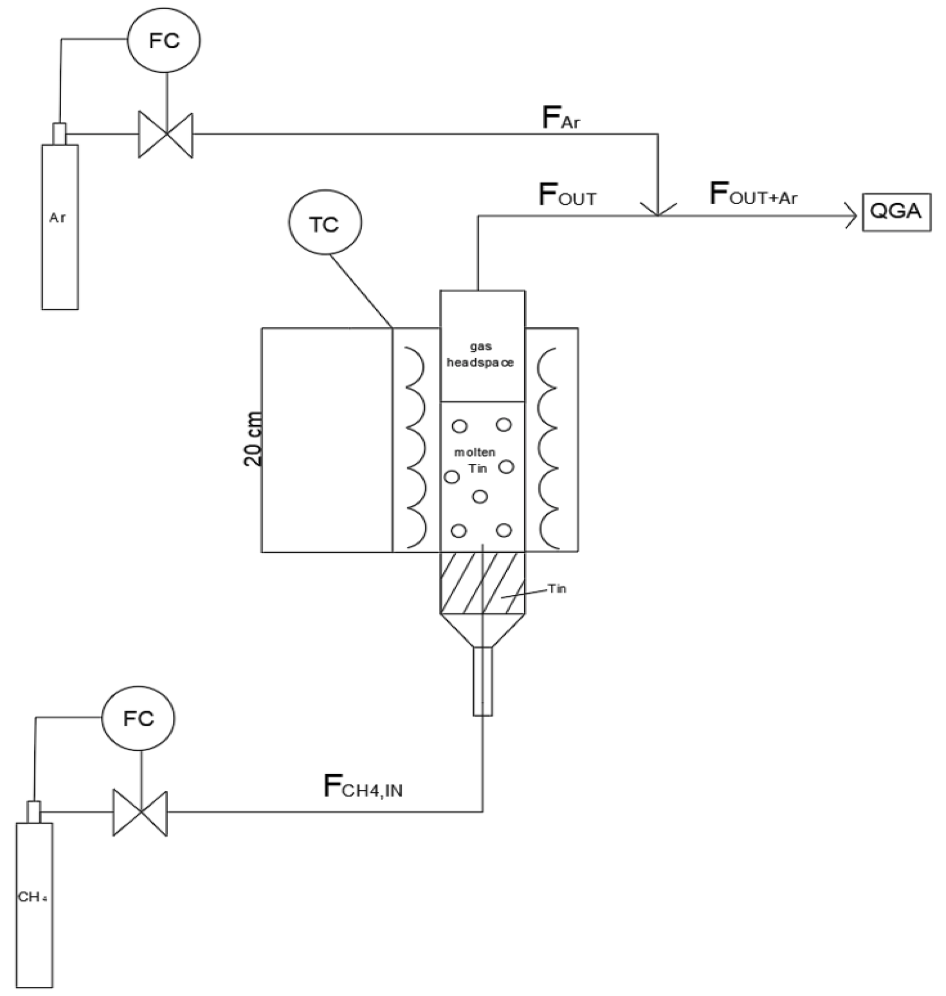
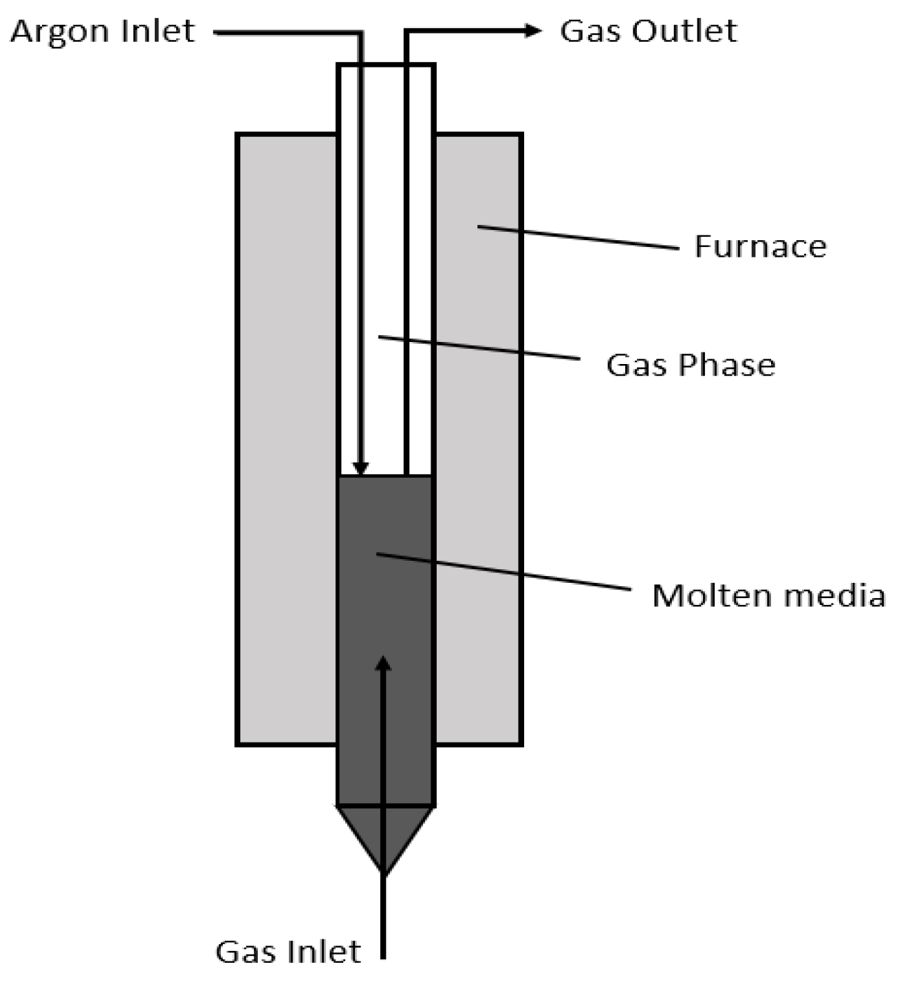
A scheme of the experimental set up and the reactor configuration schemes are reported in Figure 2 and Figure 3.
The possibility of cooling the tin surface with Argon was evaluated for the 6 mm ID reactor. In this way, it was possible to slow down the cracking kinetics and avoid a reaction in the gas phase.
The carbon produced was separated by a trap at the reactor exit and the gas was sent to a mass spectrometer analyzer QGA-Hiden.
The experimental CH4 conversion for each reactor diameter is reported in Table 1.
2.2. Simplified Kinetics Model
The methane cracking mechanism in a liquid bubble reactor is determined by both the reaction kinetics and the hydrodynamics of gas rising in the bath. In this study, only the kinetics aspects are analyzed inside the molten media phase by assuming that there are bubbles with a constant diameter along the entire reactor height. Therefore, the mass transfer phenomena effects are not currently considered. This simplified hypothesis will be removed in an updated model based on a dedicated experimental campaign.
In general, in a molten metal, as the methane bubbles rise, two types of reactions occur: one at the center of the bubbles where the methane is not in contact with the liquid, and one at the bubble interface where the gas is in direct contact with the molten media [2]. In this study, it is assumed that the prevalent contribution to methane conversion is due to the heterogeneous surface reaction at the gas/liquid–metal interface; the reaction rate is therefore proportional to the specific contact surface area, which depends on the size distribution of the bubbles [13].
The metal bath, due to its high thermal conductivity, is assumed to have a uniform temperature, independent of the heat required by the reaction [6,20].
The mathematic model developed is based on the methane mass balance inside the molten tin. The methane mass balance is defined in space, along the axial axis of the reactor, and in time. The equations reported from here on were solved using the Gproms software.
The methane mass balance (A = CH4) can be written as follows:
A first-order linear reaction kinetics with respect to methane is considered [21]:
where is the rate coefficient of the catalytic reaction (Equation (17)) and is the concentration of methane as a function of height and time.
The decomposition of methane is a reversible reaction. In the model developed, only the forward reaction is considered, since it can be assumed that the contribution of the backward reaction tends to be zero at the high temperatures analyzed [22,23].
The methane flow rate, as a function of height and time, can be written as follows:
Xa represents methane conversion, defined as follows:
where represents the methane inlet flow rate, represents the methane initial concentration and εA is derived from stoichiometry and defined as follows:
where represents the sum of the stoichiometric coefficients and represents the molar fraction of methane.
The final balance obtained by combining all the equations above is as follows:
with the following initial conditions:
The specific contact surface area between the methane bubble and the liquid metal, , is an important process parameter, since by increasing its value, a higher methane conversion can be reached. It is calculated as follows [24]:
where db is the bubble diameter and ε is the gas hold up.
As reported in Equation (10), the specific contact surface is also inversely proportional to the diameter of the bubble. This confirms that small bubbles lead to high methane conversions, as also reported in the literature [2].
As explained at the beginning of this section, the bubble diameter is assumed to be constant along the reactor height. The bubble diameter is estimated using Tate’s law, assuming that there are no viscous effects, no interactions between the bubbles, that there is a vertical rising pathway, and that there are no variations in the molten surface tension [25]:
where
Gas hold-up can be defined as the volume fraction of gas in the total volume of the gas–liquid phase in the bubble column. A smaller gas hold-up requires a larger reactor volume given the same hydrogen production rate, methane conversion and reaction temperature. It can be estimated as the ratio of the gas volume over the total volume of the molten bed.
where
with
As the bubble rising velocity is a function of the bubble diameter only, it is assumed constant along the entire reactor height.
The kinetic constant is defined by Arrhenius’ law:
Various studies in the literature were analyzed in order to find the values of the pre-exponential factor k0 and the activation energy Ea for thermal cracking in molten tin. The values from Rodat et al. [26] were selected since they better fitted the experimental data.
In Table 2, all the parameters fixed to solve the methane balance are reported.
3. Results
The mathematical model described above is solved using Gprom by entering different tin heights into the software. For each tin height, it is possible to calculate the rising time (Equation (14)), the volume of the molten bed (Equation (15)), the gas volume (Equation (13)) and the gas hold up (Equation (12)).
By combining these parameters to solve the mass balance, it is possible to obtain the methane conversion as a function of the tin height.
To validate this approach, the model results should be compared with the experimental data reported in Table 1. Therefore, the model was solved for 1.5, 3.3 and 6.0 cm ID reactors, considering an initial methane flowrate of 30 mL/min. For all these three cases analyzed, the bubble diameter (Equation (11)) was 2 mm and, accordingly, the rising velocity (Equation (16)) was 178.5 mm/s.
3.1. Case A: 1.5 cm and 3.3 cm ID Reactors
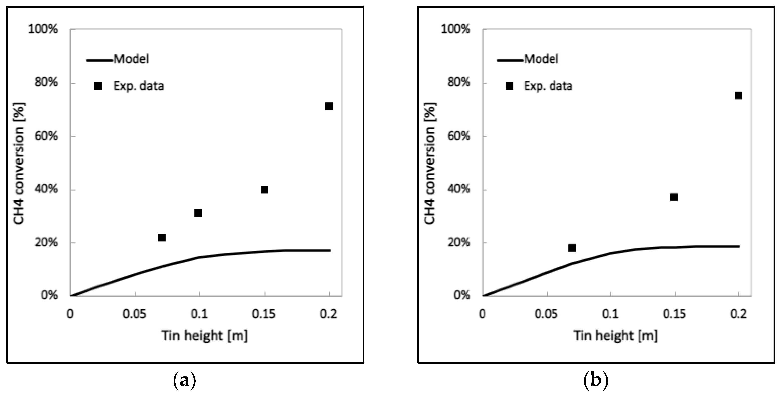
The first two cases analyzed use a 1.5 and 3.3 cm ID reactor. In Figure 4, the conversion profile vs. the tin height is reported. It is evident that the experimental data for the first two reactors are not consistent with the mathematical prediction since the experimental conversions results are much higher than the modelling ones, which tend towards an asymptote for relatively low values.
This behavior can be attributed to the small size of the reactors. The wettability of the quartz tube with tin is very low and therefore the bubbles tend to flow along the walls of the tube where the pressure drops are lower. This effect is called the wall effect. Bubble velocity increases on the quartz wall and therefore bubbles leave the tin bed quickly.
This phenomenon is inversely proportional to the diameter of the reactor and is accentuated when the tin height, and therefore the pressure drop, increases. The main effect is that the residence time of methane in the tin bath becomes very limited, leading to a methane conversion that occurs predominantly in the gas phase above the molten metal. The latter must be avoided since the solid carbon, formed outside the bath in the headspace above the molten metal, can deposit in an uncontrolled manner on the reactor surfaces, causing the consequent problems of fouling and/or clogging.
The experimental data in Figure 4 are therefore much higher than the prediction of the model since they consider both the conversion contribution in the liquid phase and in the gaseous phase. As the height of the tin increases, the values diverge more and more, confirming that the conversion occurs mostly in the headspace above the bath.
3.2. Case B: 6.0 cm ID Reactor
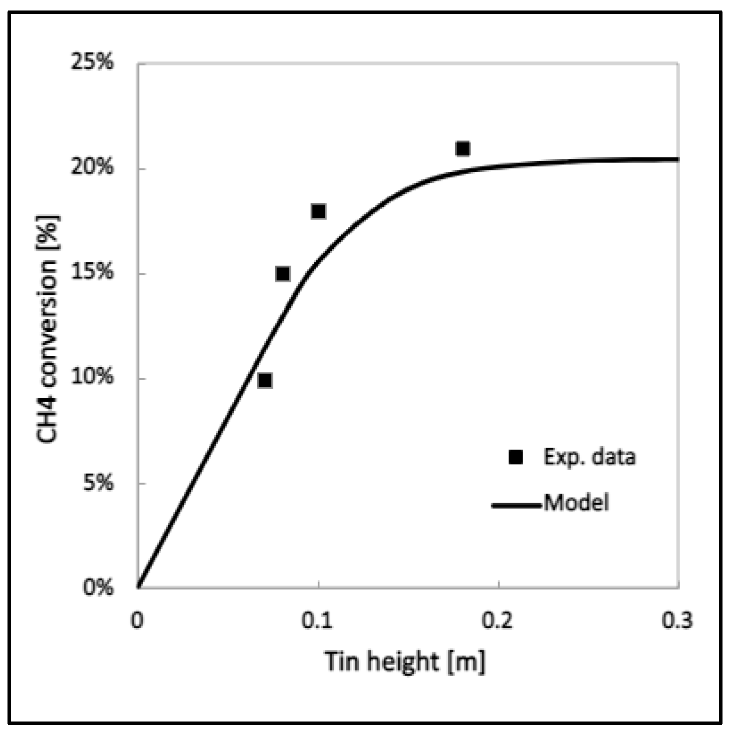
By following the modeling approach already described, it is possible to calculate the methane conversion at different tin heights also for the 6.0 cm ID reactor. The model profile is then compared with the experimental data from Table 1, and the results are shown in Figure 5.
The model conversion still presents an asymptotic behavior. However, unlike the previous cases, the experimental data are more congruent with the model prediction. This result can be attributed on the one hand to an increase in the diameter, which discourages the wall effect with the consequent flow of the bubbles. On the other hand, in the experimental tests of the 6.0 ID reactor, the conversion was measured only in the molten tin, removing the contribution in the gaseous phase. This was possible thanks to a flow of cold Argon, with the same flow rate as the methane feed, which is sent to the surface of the tin bath; in this way, the temperature in the headspace decreases with a slowdown of the kinetics, preventing conversion into the gaseous phase.
The described procedure is only applicable for the 6.0 cm ID reactor due to geometrical constraints.
The main result is that, despite the fact that the mass of the tin is greater than in the previous cases (the volume is greater since at the same relative height, the diameter is bigger), the experimental points in Figure 5 have shifted downwards with respect to those in Figure 4. The values of conversion for the 1.5 cm and 3.3 cm ID reactors should then be corrected by subtracting the conversion in the gaseous phase:
The conversion into the gaseous phase can be estimated using experimental tests on the empty reactor, which will be the object of a future experimentation campaign.
4. Discussion
By analyzing the results obtained, it may be concluded that the simplified model describes the experimental data quite accurately. Figure 5 also reflects the methane conversion trend reported in the literature for a similar reactor configuration [2,13]. The curve flattening is due to the small size of the reactor, which leads to a maximum conversion of 20%. This value corresponds to a tin height of about 20 cm, above which the molten metal seems to have no more influence.
It can be concluded that the approach developed is validated.
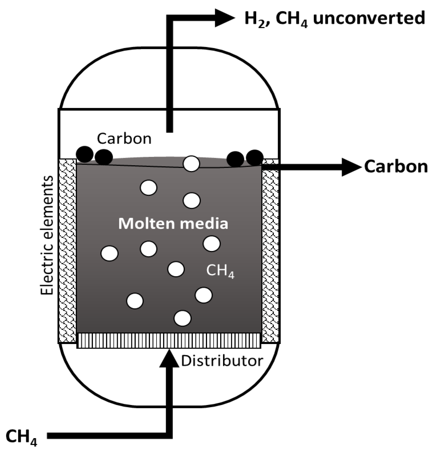
After this validation, the model is used to predict the methane conversion for an industrial liquid bubble reactor, which is schematized in Figure 6.
The reactor details are described in the patent applied, which will be published in 2023 [12]. It consists of a metallic reactor internally coated with refractory material and filled with molten tin. The metal is maintained at a constant temperature of 1000 °C by electric elements immersed in the molten bath. The methane enters inside the molten tin as bubbles through a gas distributor placed at the bottom of the reactor. The geometry and the dimensions of the reactor have been optimized in the same patents mentioned above.
The main parameters fixed are reported in Table 3.
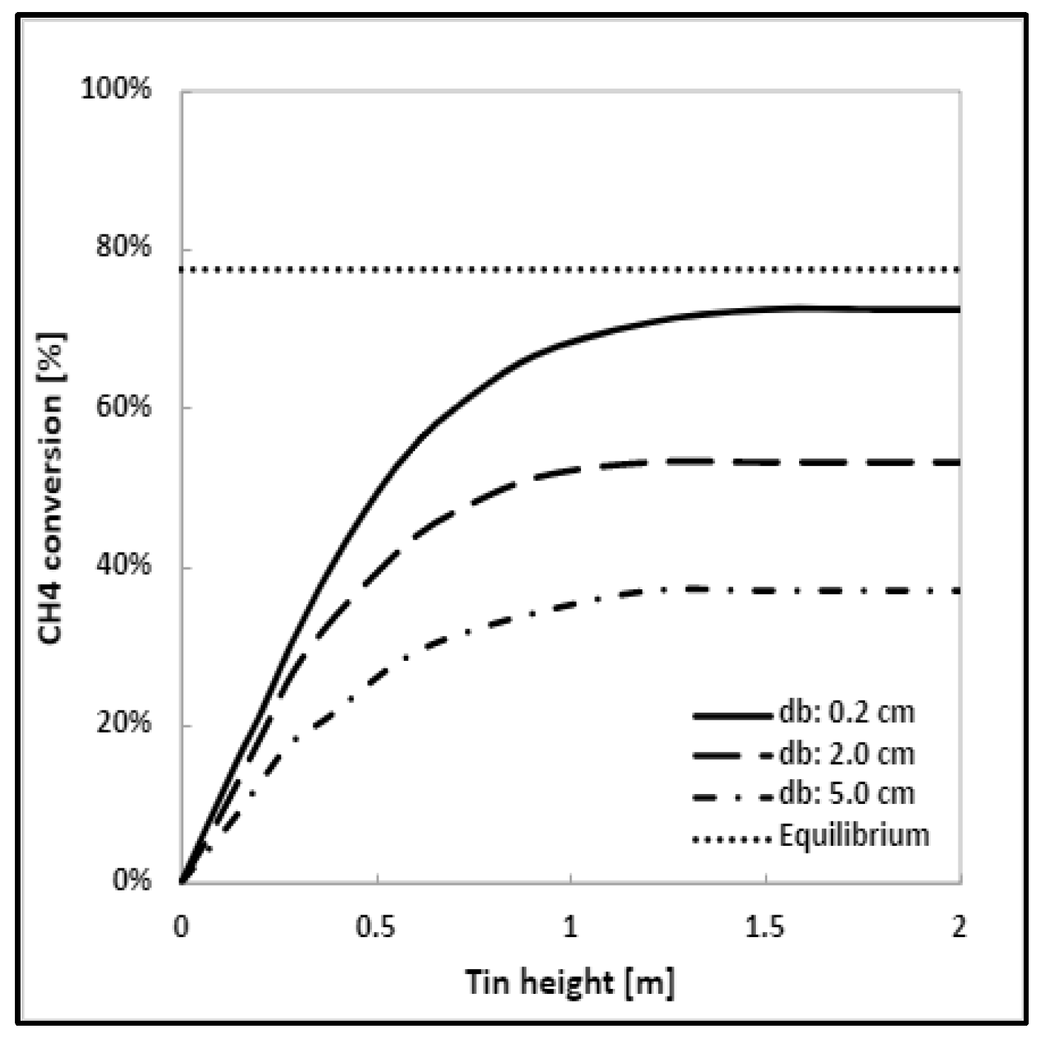
As already stated, the conversion is strongly influenced by the diameter of the gas bubble since it increases as the bubble diameter decreases. For this reason, three different bubble diameters are analyzed: 0.2 cm, 2.0 cm and 5.0 cm. For each of them, rising velocities (Equation (16)) of 17.85 cm/s, 36.96 cm/s and 49.37 cm/s were calculated, respectively.
Like the lab cases, the model is solved on Gproms, by entering different tin heights into the software: for each of them, the rising time (Equation (14)), the volume of the molten bed (Equation (15)), the gas volume (Equation (13)), the gas hold up ε (Equation (12)) and the corresponding methane conversion are calculated.
In Figure 7, the methane conversion profile vs. the tin height is reported for each bubble diameter. Figure 7 shows the equilibrium conversion as well, evaluated in the same operating conditions. In addition, in this case, the conversion presents the same trend as shown in Figure 4 and Figure 5; what changes is the value at which the curve flattens out and the corresponding tin height. The latter is independent of the diameter of the bubble and is equal to 1.5 m in all cases. Instead, the methane conversion, as expected and also reported in the literature [6,26], is strongly influenced by the bubble diameter: with big bubbles, a maximum methane conversion of about 37% is obtained; this value can become double only by decreasing the diameter of the bubbles and keeping all other operating conditions equal. This demonstrates that the bubble diameter is one of the key factors for this process architecture.
The bubble diameter depends both on the characteristics of the fluid and on the geometry of the sparger. Conversions close to equilibrium can be obtained by suitably designing the sparger to guarantee a bubble diameter in the order of mm or even less.
5. Conclusions
Methane cracking on molten media represents a promising process for low-emission hydrogen production. It becomes important to understand the thermodynamic and kinetic mechanisms on which the cracking reaction occurs, in order to predict the methane conversion and optimize the reactor design.
For this purpose, a mathematical model was developed in this work. The model is based on the methane mass balance inside the molten tin. The differential equations are solved using Gproms software.
The model results were compared with the experimental data, showing an almost equal trend in the methane conversion during the molten phase.
Afterwards, the mathematical model developed is used to estimate the methane conversion in an industrial reactor at different bubble diameters. The results obtained are promising since quite high conversions can be achieved with small bubbles.
This proves that the bubble diameter is one of the main factors that plays a role in methane cracking. Finding the right compromise between the size of the sparger orifice and the tin bath height is a key parameter in the development of the technology.
Author Contributions
Conceptualization, V.C. and E.P.; methodology, V.P., G.I.; validation, E.P., G.I. and V.P.; data curation, E.B.; writing—original draft preparation, V.C.; writing—review and editing, V.C.; supervision, E.P., G.I. and V.P. All authors have read and agreed to the published version of the manuscript.
Funding
This research received no external funding.
Institutional Review Board Statement
Not applicable.
Informed Consent Statement
Not applicable.
Data Availability Statement
Not applicable.
Conflicts of Interest
The authors declare no conflict of interest.
References
- IEA-International Energy Agency. Energy Technology Perspectives 2023; IEA-International Energy Agency: Paris, France, 2023. [Google Scholar]
- Msheik, M.; Rodat, S.; Abanades, S. Methane Cracking for Hydrogen Production: A Review of Catalytic and Molten Media Pyrolysis. Energies 2021, 14, 3107. [Google Scholar] [CrossRef]
- IEA-International Energy Agency. Hydrogen; IEA-International Energy Agency: Paris, France, 2021. [Google Scholar]
- Sanchez-Bastardo, N.; Schlogl, R.; Ruland, H. Methane Pyrolysis for CO2-Free H2 Production: A Green Process to Overcome Renewable Energies Unsteadiness. Chem. Ing. Tech. 2020, 92, 1596–1609. [Google Scholar] [CrossRef]
- Harrison, S.B. Turquoise Hydrogen Production by Methane Pyrolysis. Digital Refining PTQ Q4. 2021. Available online: https://www.sbh4.de/assets/turquoise-hydrogen-production-by-methane-pyrolysis%2C-petroleum-technology-quarterly-october-2021.pdf (accessed on 29 March 2023).
- Leal Pérez, B.J.; Jiménez, J.A.M.; Bhardwaj, R.; Goetheer, E.; Annaland, M.v.S.; Gallucci, F. Methane pyrolysis in a molten gallium bubble column reactor for sustainable hydrogen production: Proof of concept & techno-economic assessment. Int. J. Hydrog. Energy 2021, 46, 4917–4935. [Google Scholar]
- Bartholomew, C.H. Mechanism of catalyst deactivation. Appl. Catal. A Gen. 2001, 212, 17–60. [Google Scholar] [CrossRef]
- Silva, J.A.; Santos, J.B.O.; Torres, D.; Pinilla, J.L.; Suelves, I. Natural Fe-based catalysts for the production of hydrogen and carbon nanomaterials via methane decomposition. Int. J. Hydrog. Energy 2021, 46, 35137–35148. [Google Scholar] [CrossRef]
- Suelves, I.; Lázaro, M.J.; Moliner, R.; Pinilla, J.L.; Cubero, H. Hydrogen production by methane decarbonization: Carbonaceous catalysts. Int. J. Hydrog. Energy 2007, 32, 3320–3326. [Google Scholar] [CrossRef]
- Parfenov, V.; Nikitchenko, N.V.; Pimenov, A.A.; Kuz’min, A.E.; Kulikova, M.V.; Chupichev, O.B.; Maksimov, A.L. Methane Pyrolysis for Hydrogen Production: Specific Features of Using Molten Metals. Russ. J. Appl. Chem. 2020, 93, 625–632. [Google Scholar] [CrossRef]
- Rahimi, N.; Kang, D.; Gelinas, J.; Menon, A.; Gordon, M.J.; Metiu, H.; McFarland, E.W. Solid carbon production and recovery from high temperature methane pyrolysis in bubble columns containing molten metals and molten salts. Carbon 2019, 151, 181–191. [Google Scholar] [CrossRef]
- Epstein, M.; Iaquaniello, G.; Salladini, A.; Borgogna, A.; Palo, E. Processo e Apparato per la Produzione di Idrogeno Mediante Cracking di Metano e di Idrocarburi a Bassa Emissione di CO2. Patent PTC/IB2022/060932, 14 November 2022. [Google Scholar]
- Catalan, L.J.; Rezaei, E. Coupled hydrodynamic and kinetic model of liquid metal bubble reactor for hydrogen production by noncatalytic thermal decomposition of methane. Int. J. Hydrog. Energy 2020, 45, 2486–2503. [Google Scholar] [CrossRef]
- Abánades, A.; Rubbia, C.; Salmieri, D. Technological challenges for industrial development of hydrogen production based on methane cracking. Energy 2012, 46, 359–363. [Google Scholar] [CrossRef]
- Tyrer, D. Production of Hydrogen. USA Patent 1803221, 28 April 1931. [Google Scholar]
- Steinberg, M. Fossil fuel decarbonization technology for mitigating global warming. Int. J. Hydrog. Energy 1999, 24, 771–777. [Google Scholar] [CrossRef]
- Serban, M.; Lewis, M.A.; Marshall, C.L.; Doctor, R.D. Hydrogen Production by Direct Contact Pyrolysis of Natural Gas. Energy Fuels 2003, 17, 705–713. [Google Scholar] [CrossRef]
- Geißler, T.; Plevan, M.; Abanades, A.; Heinzel, A.; Mehravaran, K.; Rathnam, R.; Rubbia, C.; Salmieri, D.; Stoppel, L.; Stuckrad, S.; et al. Experimental investigation and thermo-chemical modeling of methane pyrolysis in a liquid metal bubble column reactor with a packed bed. Int. J. Hydrog. Energy 2015, 40, 14134–14146. [Google Scholar] [CrossRef]
- Catalan, L.J.; Rezaei, E. Modelling the hydrodynamics and kinetics of methane decomposition in catalytic liquid metal bubble reactors for hydrogen production. Int. J. Hydrog. Energy 2022, 47, 7547–7568. [Google Scholar] [CrossRef]
- Borgogna; Iaquaniello, G.; Biagioni, V.; Murmura, M.A.; Annesini, M.C.; Cerbelli, S. Estimate of the Height of Molten Metal Reactors for Methane Cracking. Chem. Eng. Trans. 2022, 96, 427–432. [Google Scholar]
- Upham, D.C.; Agarwal, V.; Khechfe, A.; Snodgrass, Z.R.; Gordon, M.J.; Metiu, H.; McFarland, E.W. Catalytic molten metals for the direct conversion of methane to hydrogen and separable carbon. Science 2017, 358, 917–921. [Google Scholar] [CrossRef]
- Paxman, D.; Trottier, S.; Flynn, M.R.; Kostiuk, L.; Secanell, M. Experimental and numerical analysis of a methane thermal decomposition reactor. Int. J. Hydrog. Energy 2017, 42, 25166–25184. [Google Scholar] [CrossRef]
- Trommer, D.; Hirsch, D.; Steinfeld, A. Kinetic investigation of the thermal decomposition of CH4 by direct irradiation of a vortex-flow laden with carbon particles. Int. J. Hydrog. Energy 2004, 29, 627–633. [Google Scholar] [CrossRef]
- Ojha, A.; Al Dahhan, M. Investigation of local gas holdup and bubble dynamics using four-point optical probe technique in a split-cylinder airlift reactor. Int. J. Multiph. Flow 2018, 102, 1–15. [Google Scholar] [CrossRef]
- Kulkarni, A.A.; Joshi, J.B. Bubble Formation and Bubble Rise Velocity in Gas−Liquid Systems: A Review. Ind. Eng. Chem. Res. 2005, 44, 5873–5931. [Google Scholar] [CrossRef]
- Rodat, S.; Abanades, S.; Coulié, J.; Flamant, G. Kinetic modelling of methane decomposition in a tubular solar reactor. Chem. Eng. J. 2009, 146, 120–127. [Google Scholar] [CrossRef]
Figure 1.
CH4 equilibrium conversion at different temperatures [°C] and pressures [bar] calculated on Aspen Plus v11.
Figure 1.
CH4 equilibrium conversion at different temperatures [°C] and pressures [bar] calculated on Aspen Plus v11.

Figure 2.
Experimental set up scheme.

Figure 3.
Experimental lab reactor: reactor scheme.

Figure 4.
Model and experimental CH4 conversion [%] vs. tin height [m]. (a) Case for 1.5 cm ID reactor. (b) Case for 3.3 cm ID reactor.
Figure 4.
Model and experimental CH4 conversion [%] vs. tin height [m]. (a) Case for 1.5 cm ID reactor. (b) Case for 3.3 cm ID reactor.

Figure 5.
Model and experimental CH4 conversion [%] vs. tin height [m] for 6.0 cm ID reactor.

Figure 6.
Liquid bubble reactor scheme for CH4 cracking.

Figure 7.
Model CH4 conversion [%] vs. tin height [m] for industrial reactor at different bubble diameter db [cm].
Figure 7.
Model CH4 conversion [%] vs. tin height [m] for industrial reactor at different bubble diameter db [cm].


Table 1.
Experimental data of methane conversion.
| Reactor ID Diameter [cm] | Tin Height [cm] | Exp. CH4 Conversion [%] |
|---|---|---|
| 1.5 | 7.1 | 22.0 |
| 1.5 | 9.9 | 31.0 |
| 1.5 | 15.0 | 40.0 |
| 1.5 | 20.0 | 72.0 |
| 3.3 | 7.0 | 18.0 |
| 3.3 | 15.0 | 37.0 |
| 3.3 | 20.0 | 75.0 |
| 6.0 | 7.0 | 10.0 |
| 6.0 | 8.0 | 15.0 |
| 6.0 | 10.0 | 18.0 |
| 6.0 | 18.0 | 21.0 |
Table 2.
Parameters fixed to solve methane material balance.
| Parameter | Value |
|---|---|
| [mm] | 0.125 |
| [N/m] | 0.493 |
| [kg/m3] | 6486.1 |
| [kg/m3] | 0.145 |
| g [m/s2] | 9.81 |
| k0 [1/s] | 6.6 × 10¹³ [26] |
| Ea [kJ/mol] | 370 [26] |
Table 3.
Parameters fixed for an industrial reactor.
| Parameter | Value |
|---|---|
| Reactor diameter [m] | 1 |
| Temperature [°C] | 1000 |
| Pressure [bar] | 15 |
| Methane inlet flowrate [kg/h] | 80.0 |
Disclaimer/Publisher’s Note: The statements, opinions and data contained in all publications are solely those of the individual author(s) and contributor(s) and not of MDPI and/or the editor(s). MDPI and/or the editor(s) disclaim responsibility for any injury to people or property resulting from any ideas, methods, instructions or products referred to in the content. |
© 2023 by the authors. Licensee MDPI, Basel, Switzerland. This article is an open access article distributed under the terms and conditions of the Creative Commons Attribution (CC BY) license (https://creativecommons.org/licenses/by/4.0/).
Share and Cite
MDPI and ACS Style
Palo, E.; Cosentino, V.; Iaquaniello, G.; Piemonte, V.; Busillo, E. Thermal Methane Cracking on Molten Metal: Kinetics Modeling for Pilot Reactor Design. Processes 2023, 11, 1537. https://doi.org/10.3390/pr11051537
AMA Style
Palo E, Cosentino V, Iaquaniello G, Piemonte V, Busillo E. Thermal Methane Cracking on Molten Metal: Kinetics Modeling for Pilot Reactor Design. Processes. 2023; 11(5):1537. https://doi.org/10.3390/pr11051537
Chicago/Turabian StylePalo, Emma, Vittoria Cosentino, Gaetano Iaquaniello, Vincenzo Piemonte, and Emmanuel Busillo. 2023. "Thermal Methane Cracking on Molten Metal: Kinetics Modeling for Pilot Reactor Design" Processes 11, no. 5: 1537. https://doi.org/10.3390/pr11051537
Note that from the first issue of 2016, this journal uses article numbers instead of page numbers. See further details here.