
Description Logic Ontology-Supported Part Orientation for Fused Deposition Modelling


1
Guangxi Key Laboratory of Manufacturing System and Advanced Manufacturing Technology, School of Mechanical and Electrical Engineering, Guilin University of Electronic Technology, Guilin 541004, China
2
School of Electrical and Mechanical Engineering, Guilin Institute of Information Technology, Guilin 541004, China
*
Author to whom correspondence should be addressed.
Processes 2022, 10(7), 1290; https://doi.org/10.3390/pr10071290
Submission received: 1 June 2022
/
Revised: 17 June 2022
/
Accepted: 20 June 2022
/
Published: 30 June 2022
(This article belongs to the Special Issue Application of Artificial Intelligence Techniques in Additive Manufacturing)
Abstract
:Fused deposition modelling (FDM) is well-known as an inexpensive and the most commonly used additive manufacturing process. In FDM, build orientation is one of the critical factors that affect the quality of the printed part. However, the activity of determining a build orientation for an FDM part, i.e., part orientation for FDM, usually relies on the knowledge and experience of domain experts. This necessitates an approach that enables the capture, representation, reasoning, and reuse of the data and knowledge in this activity. In this paper, a description logic (DL) ontology-supported part orientation approach for FDM is presented. Firstly, a set of top-level entities are created to construct a DL ontology for FDM part orientation. Then a DL ontology-supported alternative orientation generation procedure, a DL ontology-supported factor value prediction procedure, and a DL ontology-supported optimal orientation selection procedure are developed successively. After that, the application of the presented approach is illustrated via part orientation on six FDM parts. Finally, the effectiveness and efficiency of the presented approach are demonstrated through theoretical predictions and printing experiments and the advantages of the approach are demonstrated via an example. The demonstration results suggest that the presented approach has satisfying effectiveness and efficiency and provides a semantic enrichment model for capturing and representing FDM part orientation data and knowledge to enable automatic checking, reasoning, query, and further reuse.
1. Introduction
Fused deposition modelling (FDM), also known as fused filament fabrication, is an additive manufacturing (AM) process that builds a three-dimensional (3D) object directly from its 3D model through selectively dispensing molten material in a layer-upon-layer manner [1]. A schematic diagram of the FDM process is shown in Figure 1. An FDM machine mainly consists of a part material spool, a support material spool, a heated nozzle, and a build platform with an elevator. The process of using an FDM machine to fabricate a 3D object is described as follows. At the beginning, the heated nozzle deposits molten material from the feedstock supply onto the cross-sectional area of the first slice to build the first layer. Then the remaining layers are successively added on top of the previous layers with the help of the build platform with an elevator. During this process, layers are fused together by deposition as the material is in a melted state. After completion, a 3D object with a support structure is built. FDM is well-known as an inexpensive AM process and the most popular AM process for domestic and hobby use. It has also achieved certain applications in industry. In the aerospace industry, FDM has been used to create aircraft interior components, which provides new opportunities for reducing the cost and improving the environmental efficiency of aircraft. In the automotive sector, FDM has been applied to develop new components with complex designs and structures, which drives weight reduction and increases the efficiency of the operating components. In the biomedical industry, FDM has been instrumental in helping doctors to plan surgeries better via providing organs that are accurate in structure and made according to personalised requirements.
In general, the process of using FDM to realise a 3D part consists of a set of activities, where part orientation is an essential one. Part orientation for FDM is an activity of determining a build orientation for an FDM part that best satisfies certain requirements on the part [2,3]. The build orientation of an FDM part is considered a fundamental factor that has a direct effect on the time and cost of manufacturing the part and an important effect on the quality of the built part [4]. In practice, part orientation for FDM is usually performed by a process planner according to his or her knowledge and experience. There is not yet a tool with autonomous decision-making capability for this activity. This necessitates a part-orientation approach that enables the capture, representation, reasoning, and reuse of the data and knowledge used and generated in the activity.
In this paper, a description logic (DL) ontology-supported approach for FDM part orientation is presented. A DL ontology is a formalised specification of concepts, relations, instances, and axioms in a domain, which provides effective means to capture, represent, infer, and reuse domain knowledge [5]. An important feature of a DL ontology is that it can represent the semantics explicitly, which makes it possible to achieve semantic interoperability between two different systems. In the presented DL ontology-supported approach, the data and knowledge in part orientation for FDM are formalised in DL [6] and represented and stored in web ontology language (OWL) [7]. As advantages of the approach, consistency checking, knowledge reasoning, and semantic query can be performed automatically and reuse of the data and knowledge can be achieved easily.
The rest of the paper is organised as follows: a review and analysis of related work is made in Section 2; the details of the presented DL ontology-supported approach are described in Section 3; Section 4 documents an illustration of the application of the approach, a demonstration of its effectiveness and efficiency, and an explanation of its advantages. Section 5 ends the paper with a conclusion.
2. Related Work
Research topics related to the present paper include DL ontologies in AM and AM part orientation. In this section, an overview of the main existing work on each topic is respectively provided. Then the research gap is identified based on the overviews.
2.1. Main Existing Work on DL Ontologies in AM
During the past two decades, the application of DL ontologies in AM has gained importance and popularity. Many researchers developed ontologies or ontology-supported approaches to assist certain tasks in AM: Yim and Rosen [8] presented an ontology-supported case-based reasoning approach to assist AM process planning; Yim and Rosen [9] developed a ontology-based repository for AM design problems; Liu and Rosen [10] proposed an ontology-supported knowledge modelling and reuse approach for AM process planning; Witherell et al. [11] constructed an ontology-based metamodel for composable and reusable laser powder bed fusion process; Eddy et al. [12] developed an ontology-based intelligent tool for AM knowledge management; Roh et al. [13] constructed an ontology-based laser and thermal metamodel for laser powder bed fusion; Lu et al. [14] presented a set of ontology-supported digital solutions for integrated and collaborative AM; Assouroko et al. [15] proposed an ontology-supported approach for characterising model fidelity in laser powder bed fusion; Dinar and Rosen [16] developed a design for AM ontology; Kim et al. [17] proposed an ontology-based approach to link AM design to AM process planning; Hagedorn et al. [18] presented an ontology-supported approach for innovative design for AM; Liang [19] proposed an ontology-oriented knowledge methodology for AM process planning; Kim et al. [20] developed a design for AM ontology to support manufacturability analysis; Sanfilippo et al. [21] constructed an ontology to represent the data and knowledge in the AM value chain; Ali et al. [22] developed a product life cycle ontology for AM; Xiong et al. [23] established an ontology-supported process planning framework for wire arc AM; Ko et al. [24] studied machine learning and ontology based design rule construction for laser powder bed fusion; Chen et al. [25] studied ontology-driven learning of Bayesian network for causal inference and quality assurance in laser powder bed fusion; Roh et al. [26] established an ontology-based process map for laser powder bed fusion; Mayerhofer et al. [27] studied ontology-driven manufacturability analysis for lithography-based ceramic manufacturing; Jarrar et al. [28] presented an ontology-based approach for a decision support system in AM; Park et al. [29] studied ontology-supported collaborative knowledge management to identify data analytics opportunities in laser powder bed fusion; Li et al. [30] developed an ontology for knowledge representation in process planning for laser powder bed fusion.
As can be seen from the description above, each ontology/approach has its specific usage in AM. The ontologies/approaches in [8,9,10,12,14,16,17,18,19,20,21,22,28] are targeted at general AM processes, while each of the remaining ones is presented for one specific AM process, including laser powder bed fusion, wire arc AM, or lithography-based ceramic manufacturing. Among those targeted at general AM processes, the ontologies/approaches in [8,10,16,17,19,20] are related to part orientation for FDM. However, their main purposes are not to support this activity. They need major modifications and extensions to be used for it.
2.2. Main Existing Work on AM Part Orientation
As with the application of DL ontologies in AM, computer-aided part orientation for AM is also a hot research topic in academia. There have been a large number of approaches proposed for this topic. Two comprehensive reviews of these approaches have been made in [2,3]. According to these reviews, existing AM part orientation approaches can be categorised into one-step and two-step approaches.
A one-step approach generally adopts a search algorithm to directly search for an orientation that best meets certain requirements from an infinite solution space. The commonly used search algorithms include the exhaustive search algorithm [31,32,33,34,35,36] and heuristic search algorithms, such as the genetic algorithm [37,38,39,40,41,42], non-dominated sorting genetic algorithm II [43,44], particle swarm optimisation algorithm [45,46], electromagnetism-like mechanism algorithm [47], bacterial foraging optimisation algorithm [48], sequential quadratic programming algorithm [49], and S-metric selection evolutionary multi-objective algorithm [50]. A prominent feature of one-step approaches is that they are applicable to all forms of 3D models in theory. However, it is difficult to balance the effectiveness of the resultant orientation and efficiency of the search process when setting the rotation step size in the approaches based on exhaustive search; the approaches based on heuristic search are easy to fall into local optima. In addition, one-step approaches are usually time-consuming because they need to traverse a huge solution space [3].
Unlike one-step approaches, a two-step approach first shrinks the solution space by generating a certain number of alternative orientations and then selects an orientation that best meets certain requirements from the generated alternatives. The techniques applied to generate alternative orientations mainly include shape feature recognition [51,52,53,54], convex hull generation [55], quaternion rotation [56,57], and triangular facet clustering [58,59]. The techniques used to select an optimal orientation mainly include deviation model [51], weighted sum model [53,54,55,57,58,60], deviation-similarity model [61], ordered weighted averaging operator [56], fuzzy aggregation operators [62,63], and double-layer priority aggregation multi-criterion decision-making [64]. Two-step approaches are generally efficient. However, the approaches using shape feature recognition cannot be applied to free-form models since it is difficult to define the shape features for these models. The approach using convex hull generation could introduce an accuracy issue as the convex hull is an approximate model. The approaches using quaternion rotation could miss the real optimal orientation because the alternative orientations are generated based on randomly obtained rotation axes [3]. Compared to these approaches, the approaches using triangular facet clustering can work for all forms of 3D models and would not introduce an accuracy issue. Further, the approach in [59] is, as demonstrated in [59], more stable and efficient than the approach in [58]. However, this approach does not consider the capture, representation, reasoning, and reuse of the data and knowledge in part orientation and it is developed just for the laser powder bed fusion process.
2.3. Research Gap
Based on the overviews above, a research gap is evident: there is not yet an FDM part orientation approach that supports the capture, representation, reasoning, and reuse of related data and knowledge. In this paper, DL ontology is introduced into the two-step approach using triangular facet clustering and weighted sum model in [59,60] to develop an ontology-supported approach for FDM part orientation. Compared to the approach in [59,60], the developed approach is targeted at the FDM process and would need different prediction models for build orientation factors. More importantly, the developed approach can fill the research gap.
3. DL Ontology-Supported Part Orientation
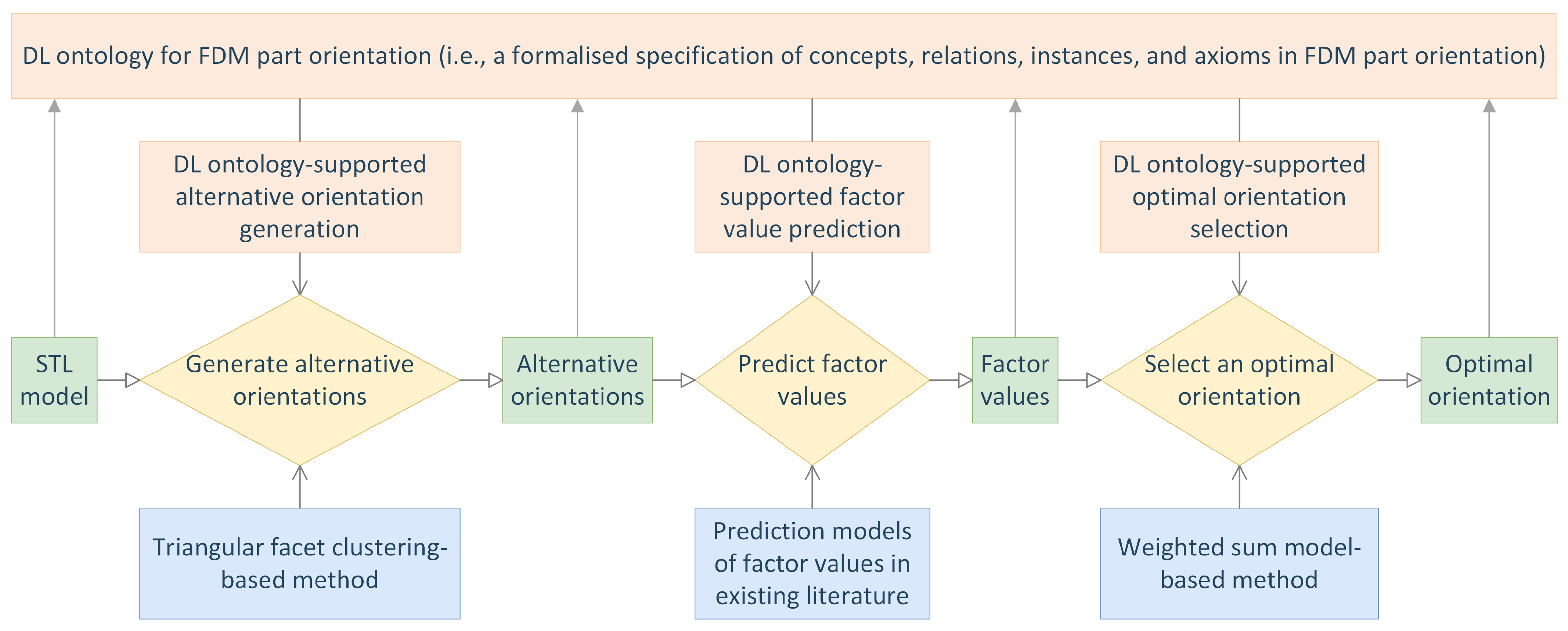
In this section, the developed DL ontology-supported approach is described in detail. A schematic representation of this approach is given in Figure 2. The approach takes as input the STL (standard tessellation language) model of an FDM part and outputs an optimal orientation to build the part. It consists of a step of alternative orientation generation, a step of factor value prediction, and a step of optimal orientation selection, which are supported by a DL ontology for FDM part orientation and the triangular facet clustering-based method in [59], the DL ontology and a set of prediction models of factor values in the existing literature, and the DL ontology and the weighted sum model-based method in [60], respectively. The present section documents the development of a set of top-level entities in the DL ontology first and then respectively explains the details of the three steps.
3.1. Top-Level Entities in DL Ontology for FDM Part Orientation
Part orientation for FDM takes as input a 3D model for AM, an FDM material, an FDM machine, and certain requirements and outputs a certain number of alternative build orientations or an optimal build orientation. There are currently many formats of 3D models for AM, where the most widely used one is the STL model [65]. The requirements on an FDM part are generally described by a set of orientation factors, which mainly include support volume, build time, part cost, volumetric error, surface roughness, and part properties (e.g., hardness, elongation, tensile strength, and fatigue performance) [2,3]. Only the first five factors are considered in the developed DL ontology-supported approach since suitable prediction models of part properties where the build orientation of an FDM part is a variable were not found in existing literature.
According to the description above, a DL ontology for FDM part orientation was created in Protégé [66] and twenty-five top-level concepts were created in the DL ontology and shown in Figure 3. Among these concepts, Fdm, FdmMachine, FdmMaterial, FdmPart, and PartOrientation are composite concepts, while the rests are atomic concepts. The DL definitions of the five composite concepts are as follows:
where isBasedOn, hasEnergySource, hasBuildMechanism, isApplicableFor, isBuiltUsing, hasAimOfDesigning, hasInput, and hasOutput are object relations.
3.2. DL Ontology-Supported Alternative Orientation Generation
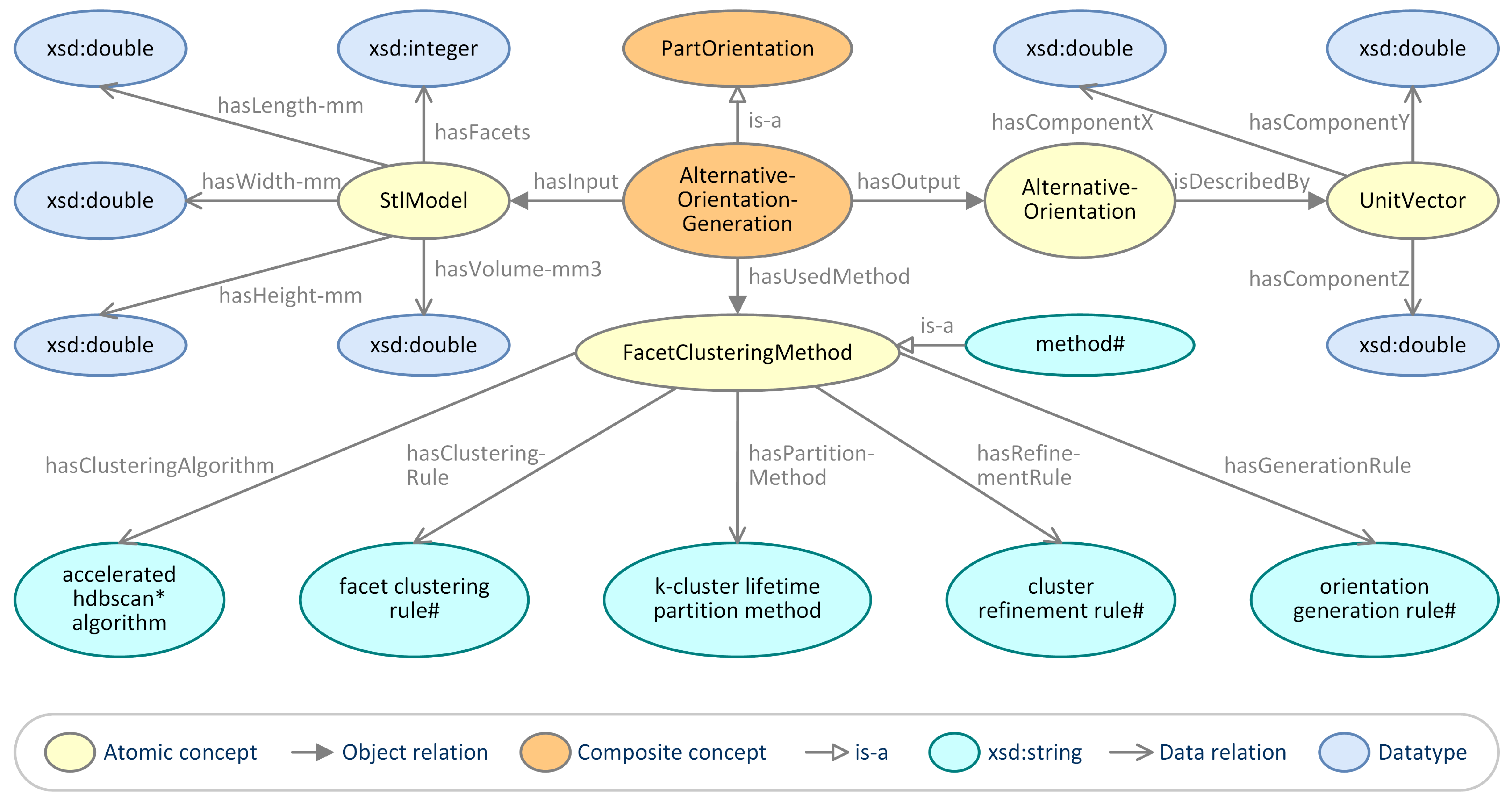
Alternative orientation generation is a part orientation task that aims to generate a certain number of alternative build orientations. In the developed DL ontology-supported approach, this task is completed using the triangular facet clustering-based method in [59]. According to the method, alternative orientation generation takes as input an STL model of an FDM part and outputs a set of alternative build orientations for the part. The basic geometric information of an STL model includes the number of its facets, the length, width, and height of its bounding box, and its total volume. An alternative build orientation is described by a unit vector (x, y, z) (where x, y, and z are the X, Y, and Z components of the unit vector, respectively). The generation process consists of a step of facet clustering and a step of orientation generation. In the first step, a set of meaningful facet clusters are generated by the accelerated hdbscan algorithm, a facet clustering rule, and the k-cluster lifetime partition method. In the second step, a certain number of alternative build orientations are obtained using an orientation generation rule or a cluster refinement rule and the orientation generation rule.
To represent the data and knowledge in alternative orientation generation, three concepts named AlternativeOrientationGeneration, UnitVector, and FacetClusteringMethod were created in the DL ontology, where AlternativeOrientationGeneration is a composite concept that is defined by the following terminological axiom:
where hasAimOfGenerating and hasUsedMethod are two object relations. Further, an object relation named isDescribedBy, thirteen data relations named hasFacets, hasLength-mm, hasWidth-mm, hasHeight-mm, hasVolume-mm3, hasComponentX, hasComponentY, hasComponentZ, hasClusteringAlgorithm, hasClusteringRule, hasPartitionMethod, hasRefinementRule, and hasGenerationRule, and six instances named method in [59], accelerated hdbscan* algorithm, facet clustering rule in [59], k-cluster lifetime partition method, cluster refinement rule in [59], and orientation generation rule in [59] were also created in the DL ontology. On the basis of the created entities, an ontological view of alternative orientation generation is delineated in Figure 4.
3.3. DL Ontology-Supported FACTOR Value Prediction
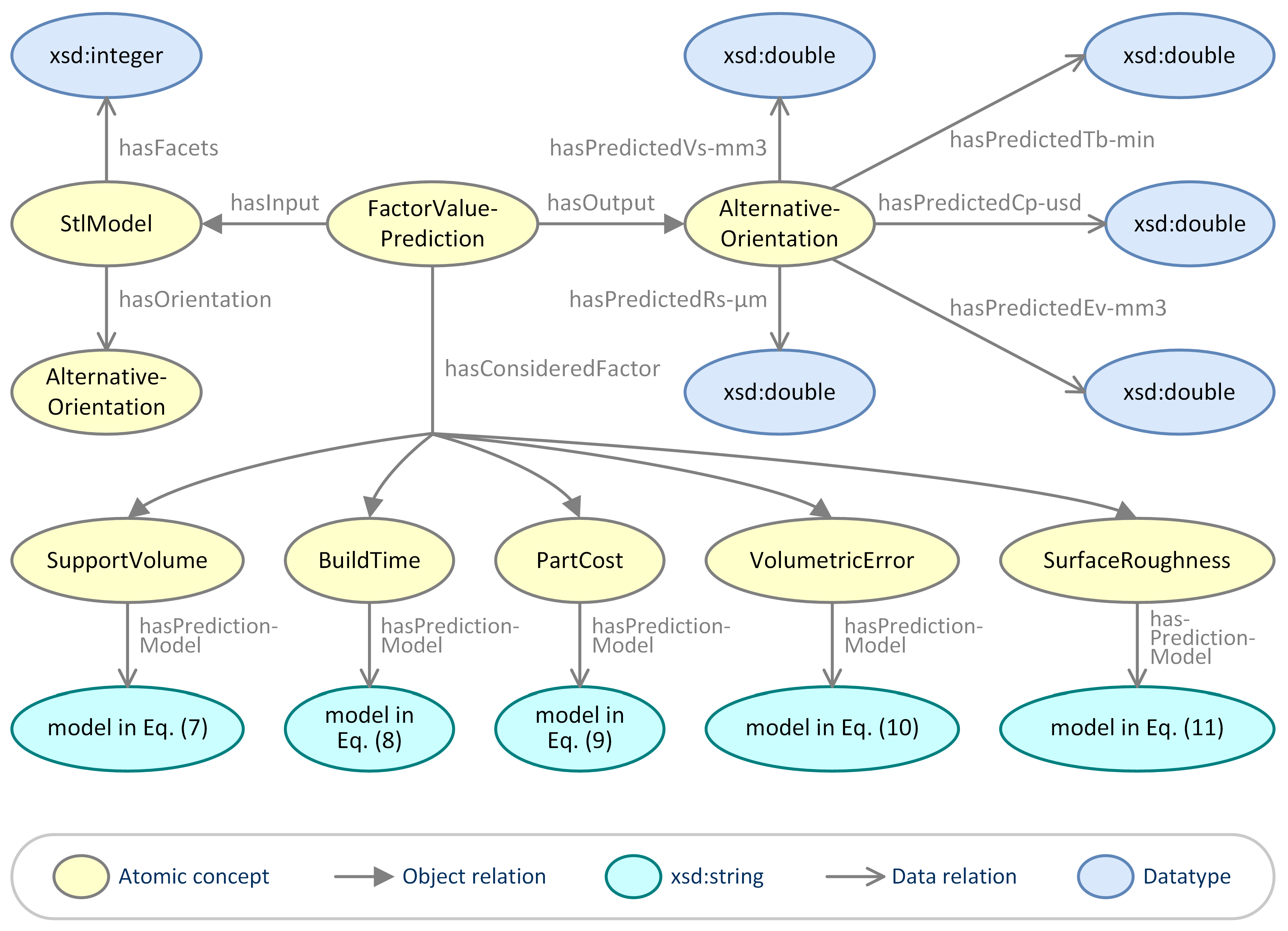
Factor value prediction is a task before optimal orientation selection that aims to predict the values of the factors considered in part orientation using certain theoretical models according to the 3D model and alternative build orientations of a part. In the developed DL ontology-supported approach, five orientation factors including support volume, build time, part cost, volumetric error, and surface roughness are considered. Prediction of the value of each factor is respectively described in detail as follows:
- Support volume. In the FDM process, the support structure is needed to sustain the overhanging areas to resist deformation or collapse, reduce part distortion caused by thermal gradients, or balance a building part to avoid shift or collapse [67]. In the weighted sum model-based method in [60], the amount of the support structure, i.e., support volume, is predicted using Autodesk Meshmixer, which is accurate but not efficient. The developed approach uses a more efficient theoretical model from [68]:where is the predicted support volume in an orientation O, n is the number of triangular facets of an STL model, is the number of downward triangular facets in O, () is the area of the i-th (j-th) triangular facet, is the average of the Z components of the three vertices of the j-th triangular facet, and is the Z component of the normal vector of the j-th triangular facet.
- Build time. Build time refers to the total time spent in building an FDM part. It is an important orientation factor for the FDM process [69]. In the weighted sum model-based method in [60], build time is predicted using a theoretical model for the laser powder bed fusion process, which is not applicable for the FDM process. The developed approach adopts a different theoretical model from [47]:where is the predicted build time in an orientation O, is a unit vector that describes O, and , , and are the three vertices of the i-th triangular facet.
- Part cost. Part cost refers to the total cost for realising an FDM part. It is also an essential orientation factor for the FDM process. In the weighted sum model-based method in [60], the part cost is predicted using a theoretical model for the laser powder bed fusion process, which cannot be applied to the FDM process. The developed approach uses a different theoretical model from [50]:where is the predicted part cost in an orientation O, is the energy cost rate, is the fixed cost rate, is the support material cost in O, and is the post-processing cost in O.
- Volumetric error. Volumetric error is one of the important part accuracy indicators. It is mainly caused by the staircase effect of the FDM process. The volumetric error of an FDM part cannot be eliminated, but it can be reduced via designing a proper build orientation. There have been a number of theoretical models for predicting the volumetric error of an FDM part [3]. The developed approach adopts a theoretical model from [47]:where is the predicted volumetric error in an orientation O, n is the number of triangular facets of an STL model, t is the layer thickness, is a unit vector that describes O, is the normal vector of the i-th facet, and is the area of the i-th triangular facet.
- Surface roughness. Surface roughness is an indicator used to measure the smoothness of a surface. It reflects the surface quality of an FDM part [70]. There have been many available theoretical models for predicting the surface roughness of an FDM part [3]. The developed approach uses a simplified version of a theoretical model from [71]:where is the predicted surface roughness (i.e., predicted ) in an orientation O, n is the number of triangular facets of an STL model, t is the layer thickness, is the sloping angle of the i-th triangular facet with respect to O, and is the area of the i-th triangular facet.
To represent the data and knowledge in factor value prediction, a concept named FactorValuePrediction, two object relations named hasOrientation and hasConsideredFactor, six data relations named hasPredictionModel, hasPredictedVs-mm3, hasPredictedTb-min, hasPredictedCp-usd, hasPredictedEv-mm3, and hasPredictedRs-μm, and five instances named model in Equation (7), model in Equation (8), model in Equation (9), model in Equation (10), and model in Equation (11) were created in the DL ontology. Based on the created entities, an ontological view of factor value prediction is depicted in Figure 5.
3.4. DL Ontology-Supported Optimal Orientation Selection
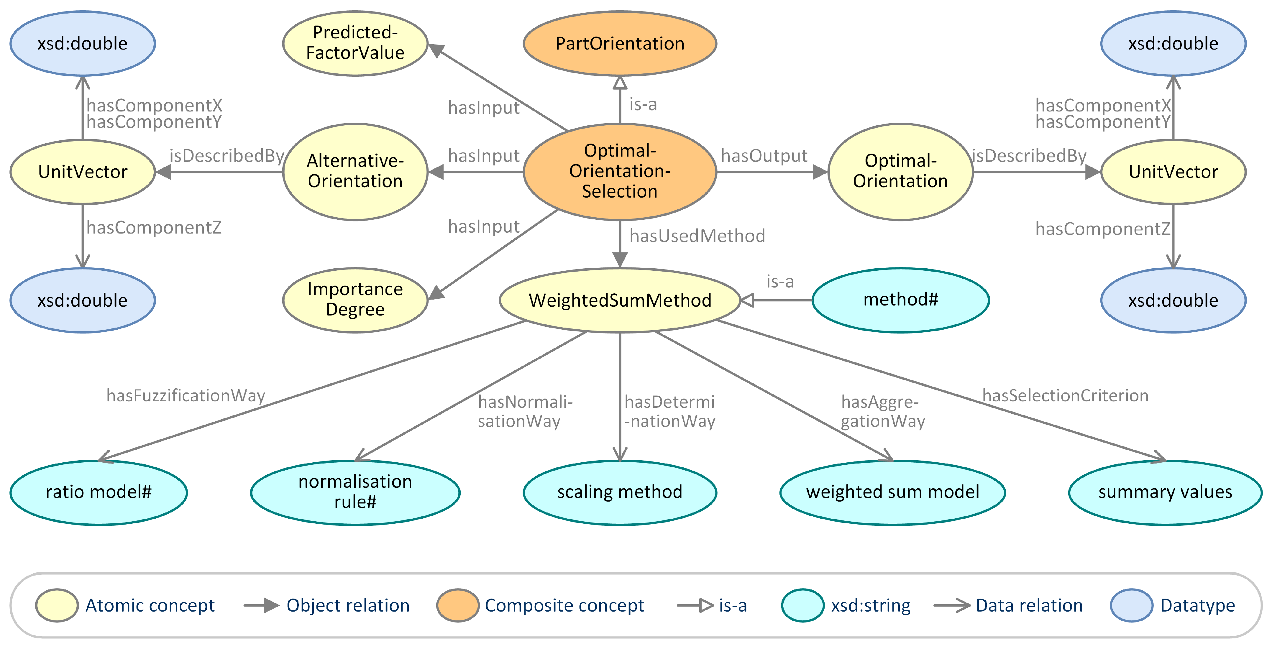
Optimal orientation selection is a part orientation task that aims to select an optimal build orientation from the generated alternative build orientations. In the developed DL ontology-supported approach, this task is completed using the weighted sum model-based method in [60]. According to the method, optimal orientation selection takes as input a set of alternative build orientations for an FDM part, the predicted factor values under each alternative orientation, and the importance degrees of factors and outputs of an optimal build orientation for the part. The selection process consists of a step of fuzzification of the predicted factor values, a step of normalisation of the fuzzy values, a step of determination of the weights of factors, a step of calculation of summary normalised fuzzy values, and a step of generation of an optimal orientation. The fuzzification, normalisation, and determination are carried out using a ratio model, a normalisation rule, and a scaling method based on pairwise comparison, respectively. The summary normalised fuzzy values are calculated using the weighted sum model and an optimal orientation is selected based on the calculation results.
To represent the data and knowledge in optimal orientation selection, four concepts named OptimalOrientationSelection, PredictedFactorValue, ImportanceDegree, and WeightedSumMethod were created in the DL ontology, where OptimalOrientationSelection is a composite concept that is defined by the following terminological axiom:
where hasAimOfSelecting is an object relation. Further, five data relations named hasFuzzificationWay, hasNormalisationWay, hasDeterminationWay, hasAggregationWay, and hasSelectionCriterion and six instances named method in [60], ratio model in [60], normalisation rule in [60], scaling method, weighted sum model, and summary values were also created in the DL ontology. On the basis of the created entities, an ontological view of optimal orientation selection is delineated in Figure 6.
4. Application, Validation, and Illustration
In this section, the application of the developed DL ontology-supported approach is first illustrated. Then its effectiveness and efficiency are demonstrated. Finally, its advantages are explained.
4.1. Application of the Approach
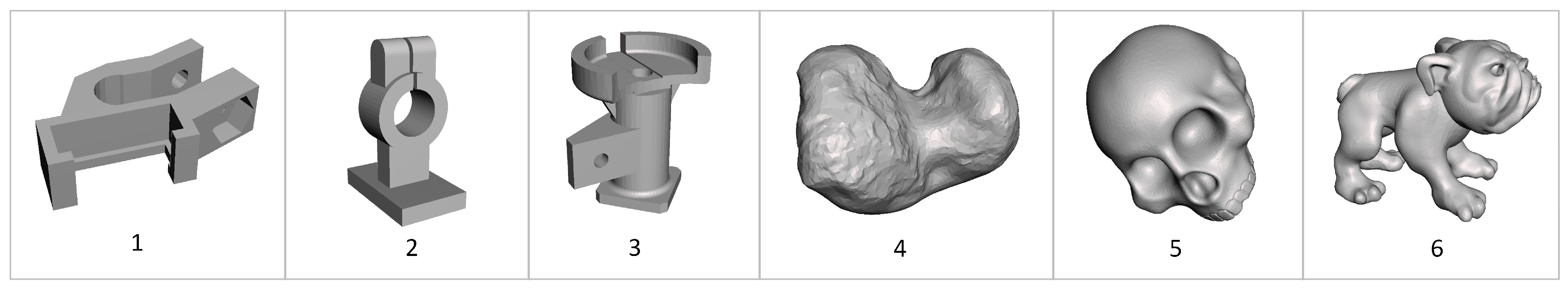
Part orientation on six FDM parts from [60] is performed to illustrate the application of the developed approach. The STL models of these parts are shown in Figure 7. The first three models are regular-form models, while the remaining three ones belong to free-form models. The basic geometric information of these models can be found in [60]. Assume that the six parts will be built using ABS (model material), PLA (support material, the unit cost is 5.64 × 10 USD/mm), and X350 (FDM machine). Some process variables are adapted or cited from [68] and are listed as follows: layer thickness is 0.2 mm; filling density is 100%; wall thickness is 1 mm; printing temperature is 260 C; infilling pattern is a zigzag pattern. Before the actual part build, part orientation on each part is needed to be carried out. Further assume that support volume, build time, part cost, volumetric error, and surface roughness are the considered orientation factors and the importance degrees of these factors are the same as they are in [60].
Based on the conditions above, the build orientation of each part can be determined using the developed approach. As an example, the build orientation of Part 1 is determined via the following three steps:
- Generate alternative orientations. The STL model of Part 1 was imported into the developed approach and a set of instances and assertions, as shown in Figure 8, were generated in the DL ontology. After executing the DL ontology-supported alternative orientation generation procedure, six alternative build orientations, as shown in Figure 9, were generated in the DL ontology.
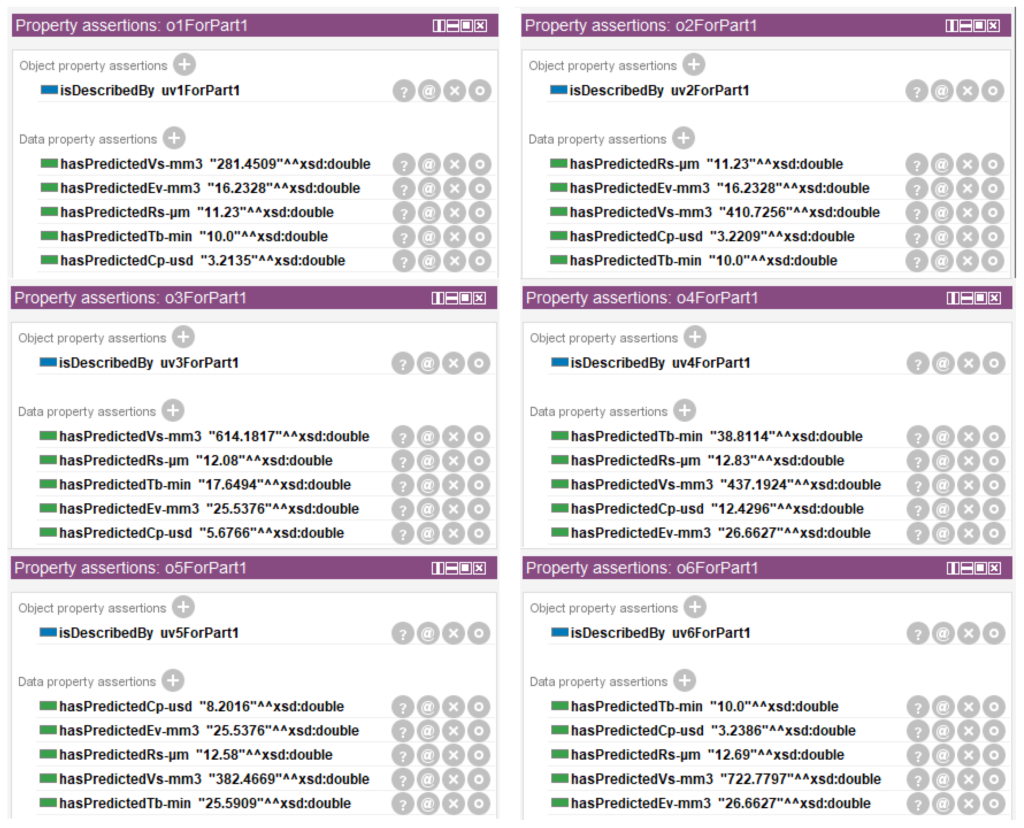
- Predict factor values. The values of support volume, build time, part cost, volumetric error, and surface roughness under the six alternative build orientations of Part 1, as listed in Figure 10, were generated in the DL ontology after executing the DL ontology-supported factor value prediction procedure.
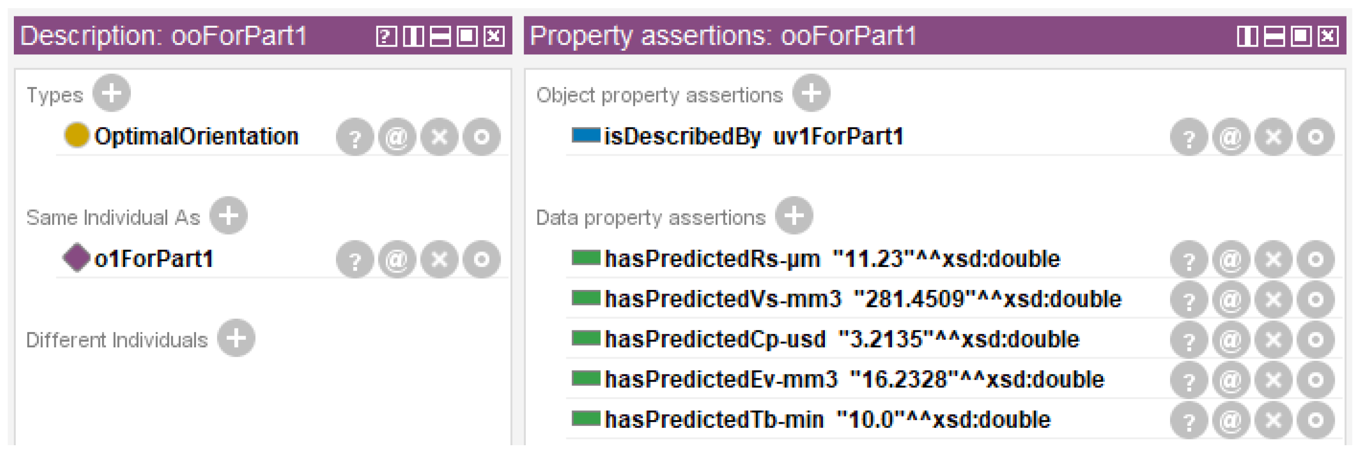
- Select an optimal orientation. An optimal build orientation, as depicted in Figure 11, was generated in the DL ontology after executing the DL ontology-supported optimal orientation selection.
Similarly, the build orientation of each of the remaining parts can also be determined via the three steps above. The determined optimal build orientations for the six FDM parts and corresponding predicted factor values are listed in Table 1.
4.2. Validation of the Approach
4.2.1. Demonstration of Effectiveness
In general, the effectiveness of a part orientation approach can be measured by the optimisation degree of the factor values in the optimal build orientation determined by this approach [60]. To demonstrate the effectiveness of the proposed approach, a theoretical comparison and an actual comparison between the approach and a one-step approach based on a genetic algorithm (GA) (the reason for choosing a GA-based approach is that it is the most representative and the GA is the most used search algorithm in existing one-step approaches) were carried out. These comparisons use the six FDM parts in Figure 7 as a benchmark. For fair comparison, both approaches consider the same orientation factors (i.e., support volume, build time, part cost, volumetric error, and surface roughness), and use the same prediction models (i.e., the predictions models from Equation (7) to Equation (11)), and have the same other input conditions. The details and results of the two comparisons are explained as follows:
- Effectiveness comparison based on theoretical predictions. The results of this comparison are listed in Table 2. As can be seen from the table, the proposed approach has 20 better values, while the GA-based approach has 10 better values. Therefore, the proposed approach is theoretically at least as effective as the GA-based approach.
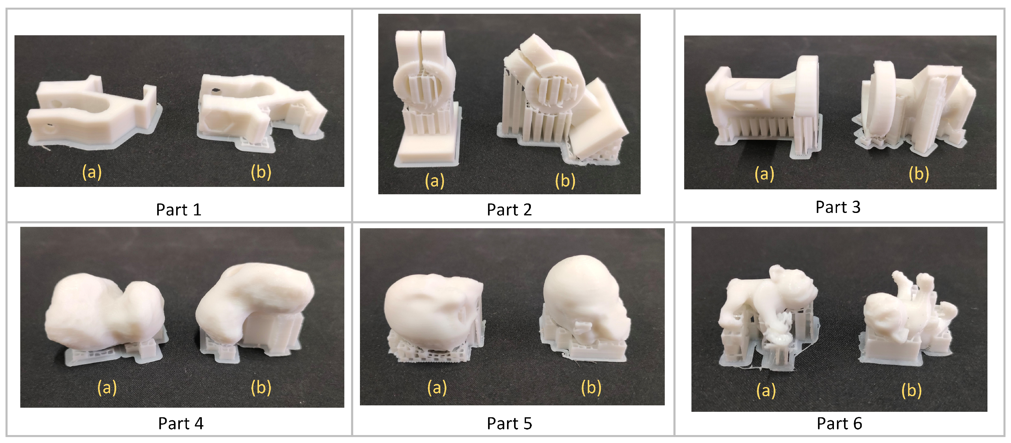
- Effectiveness comparison based on printing experiments. Each of the six parts was respectively printed using the optimal orientations determined by the GA-based approach and the proposed approach. In addition to the build orientation, the FDM material, FDM machine, process variables, and all other conditions are the same for each part. A picture of the 12 printed parts is given in Figure 12. After a part was printed, its support structure was removed and weighed to calculate the actual support volume. The actual build time of each printed part is obtained by automatic timing of the FDM machine. The actual build cost of each printed part is calculated from the build time and printing unit price. The actual volumetric error of each printed part was calculated via the volume of the part without support structure and the volume of the STL model of the part. The surface roughness of each printed part was measured by the TR210 portable surface roughness tester. During the measurement three points were randomly selected on each feature of the part and the surface roughness was measured in four different directions. The surface roughness of the pars was obtained via averaging all measurement values. The results of this comparison are listed in Table 3. It can be seen from the table that the proposed approach has 24 better values and the GA-based approach has 6 better values. Based on this, the proposed approach is at least as effective as the GA-based approach in practice.
4.2.2. Demonstration of Efficiency
The efficiency of a part orientation approach can be measured by the time it takes to generate an optimal build orientation. To demonstrate the efficiency of the proposed approach, a comparison of the time spent on part orientation between the proposed approach and the GA-based approach was carried out. This comparison also uses the six FDM parts in Figure 7 as a benchmark. For fair comparison, both approaches consider the same orientation factors, use the same prediction models, and have the same other input conditions. The results of the comparison are depicted in Figure 13. It is obvious that the proposed approach is more efficient than the GA-based approach.
4.3. Illustration of the Advantages
A prominent feature of a DL ontology is that it can explicitly represent the semantics of the data and knowledge. Benefiting from this feature, the proposed DL ontology-supported approach has advantages in supporting automatic consistency checking, knowledge reasoning, and semantic query and providing a mechanism to facilitate further reuse of the data and knowledge. The first advantage has been well illustrated via a few examples in [30]. The second advantage is explained and illustrated below.
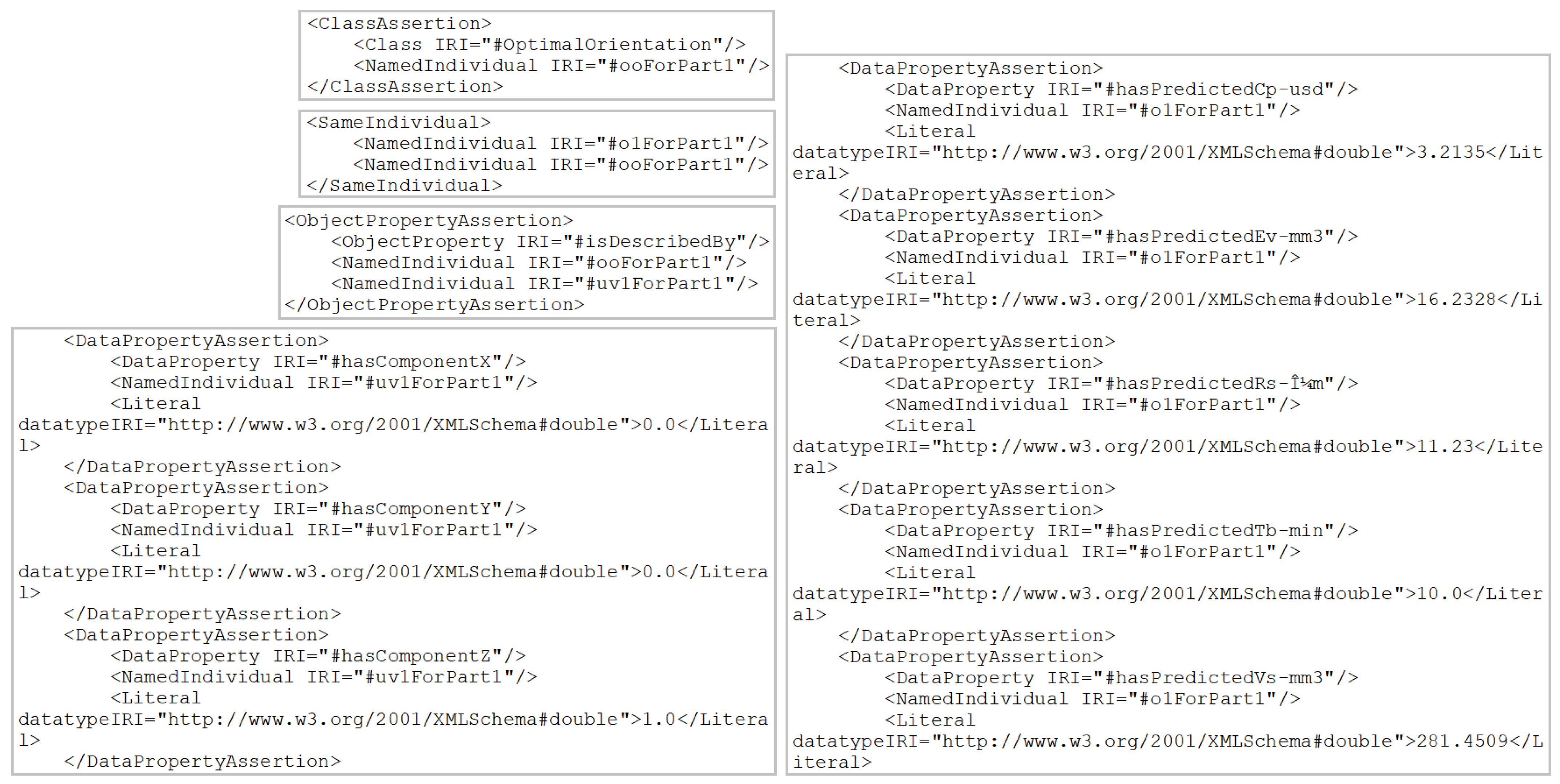
In the proposed approach, FDM part orientation data and knowledge are encoded in OWL/XML (web ontology language/extensible markup language) syntax and stored in an OWL file, which makes them human-readable, human-interpretable, computer-readable, computer-interpretable, and easy to extend and reuse. For example, encoding of the generated optimal build orientation for Part 1 in Figure 11 is depicted in Figure 14. It is easy to read and interpret by humans from the figure that ooForPart1 is an OptimalOrientation; ooForPart1 is the same as o1ForPart1; ooForPart1 is described by uv1ForPart1; uv1ForPart1 has an X component of 0.0, a Y component of 0.0, and a Z component of 1.0; Part 1 built using ooForPart1 has a predicted part cost of USD 3.2135, a predicted volumetric error of 16.2328 mm, a predicted surface roughness of 11.23 m, a predicted build time of 10.0 min, and a predicted support volume of 281.4509 mm. Since these data and knowledge are encoded in OWL/XML syntax, they are also easy to read and interpret in any software tools that support this format. This feature makes the developed DL ontology easy to extend and reuse.
5. Conclusions
In this paper, a DL ontology-supported approach for FDM part orientation is proposed. A set of top-level DL concepts, relations, and axioms are created to capture and represent the data and knowledge in general FDM part orientation activity. Based on this, a procedure of DL ontology-supported alternative orientation generation, a procedure of DL ontology-supported factor value prediction, and a procedure of DL ontology-supported optimal orientation selection are developed. The paper also documents an illustration of the application of the proposed approach and demonstrations of the effectiveness, efficiency, and advantages of the approach. The demonstration results show that the proposed approach is both effective and efficient and provides a semantic enrichment model for FDM part orientation data and knowledge to enable automatic checking, reasoning, and query and further reuse.
Future work will aim especially at extending the proposed approach to consider the orientation factors related to part properties. From the overall value chain, the properties of an FDM part (e.g., hardness, elongation, tensile strength, and fatigue performance) are usually more important than support volume, build time, part cost, volumetric error, and surface roughness. However part property factors are not considered in the proposed approach. This is generally unacceptable for practical applications, since satisfying certain quality requirements is the most fundamental condition for them and the orientation factors related to part properties are critical indicators of part quality. In the next research work, the approach would be extended to consider part property factors once suitable prediction models are available. Further, it would be interesting to extend the approach to the entire FDM part realisation process.
Author Contributions
Conceptualisation, M.H., N.Z. and Y.Q.; methodology, M.H., N.Z. and Y.Q.; software, N.Z.; validation, N.Z. and B.F.; formal analysis, N.Z. and H.Z.; investigation, N.Z.; resources, N.Z. and Z.T.; data curation, N.Z.; writing—original draft preparation, M.H., N.Z. and Y.Q.; writing—review and editing, M.H., N.Z. and Y.Q.; visualisation, N.Z. and L.Q.; supervision, project administration, funding acquisition, Y.Q. and M.H. All authors have read and agreed to the published version of the manuscript.
Funding
This work was supported by the National Natural Science Foundation of China (No. 52105511 and No. 52165064).
Institutional Review Board Statement
Not applicable.
Informed Consent Statement
Not applicable.
Data Availability Statement
Not applicable.
Conflicts of Interest
The authors declare no conflict of interest.
References
- Gibson, I.; Rosen, D.; Stucker, B. Additive Manufacturing Technologies: 3D Printing, Rapid Prototyping, and Direct Digital Manufacturing, 2nd ed.; Springer: New York, NY, USA, 2015. [Google Scholar]
- Di Angelo, L.; Di Stefano, P.; Guardiani, E. Search for the Optimal Build Direction in Additive Manufacturing Technologies: A Review. J. Manuf. Mater. Process. 2020, 4, 71. [Google Scholar] [CrossRef]
- Qin, Y.; Qi, Q.; Shi, P.; Scott, P.J.; Jiang, X. Status, issues, and future of computer-aided part orientation for additive manufacturing. Int. J. Adv. Manuf. Technol. 2021, 115, 1295–1328. [Google Scholar] [CrossRef]
- Raut, S.; Jatti, V.S.; Khedkar, N.K.; Singh, T.P. Investigation of the effect of built orientation on mechanical properties and total cost of FDM parts. Procedia Mater. Sci. 2014, 6, 1625–1630. [Google Scholar] [CrossRef] [Green Version]
- Gruber, T.R. A translation approach to portable ontology specifications. Knowl. Acquis. 1993, 5, 199–220. [Google Scholar] [CrossRef]
- Baader, F.; Calvanese, D.; McGuinness, D.L.; Nardi, D.; Patel-Schneider, P.F. The Description Logic Handbook: Theory, Implementation and Applications; Cambridge University Press: Cambridge, UK, 2003. [Google Scholar]
- McGuinness, D.L.; Harmelen, F.V. OWL Web Ontology Language Overview. 2004. Available online: https://www.w3.org/TR/owl-features/ (accessed on 16 May 2022).
- Yim, S.; Rosen, D.W. Case-Based Retrieval Approach of Supporting Process Planning in Layer-Based Additive Manufacturing. In Proceedings of the ASME 2007 International Design Engineering Technical Conferences and Computers and Information in Engineering Conference, Las Vegas, NV, USA, 4–7 September 2007. [Google Scholar]
- Yim, S.; Rosen, D.W. A repository for DFM problems using description logics. J. Manuf. Technol. Manag. 2008, 19, 755–774. [Google Scholar] [CrossRef]
- Liu, X.; Rosen, D.W. Ontology Based Knowledge Modelling and Reuse Approach of Supporting Process Planning in Layer-Based Additive Manufacturing. In Proceedings of the 2010 International Conference on Manufacturing Automation, Hong Kong, China, 13–15 December 2010. [Google Scholar]
- Witherell, P.; Feng, S.; Simpson, T.W.; John, D.B.S.; Michaleris, P.; Liu, Z.-K.; Chen, L.-Q.; Martukanitz, R. Toward Metamodels for Composable and Reusable Additive Manufacturing Process Models. J. Manuf. Sci. Eng. 2014, 136, 061025. [Google Scholar] [CrossRef]
- Eddy, D.; Krishnamurty, S.; Grosse, I.; Perham, M.; Wileden, J.; Ameri, F. Knowledge Management With an Intelligent Tool for Additive Manufacturing. In Proceedings of the ASME 2015 International Design Engineering Technical Conferences and Computers and Information in Engineering Conference, Boston, MA, USA, 2–5 August 2015. [Google Scholar]
- Roh, B.-M.; Kumara, S.R.; Simpson, T.W.; Michaleris, P.; Witherell, P.; Assouroko, I. Ontology-Based Laser and Thermal Metamodels for Metal-Based Additive Manufacturing. In Proceedings of the ASME 2016 International Design Engineering Technical Conferences and Computers and Information in Engineering Conference, Charlotte, NC, USA, 21–24 August 2016. [Google Scholar]
- Lu, Y.; Witherell, P.; Lopez, F.; Assouroko, I. Digital Solutions for Integrated and Collaborative Additive Manufacturing. In Proceedings of the ASME 2016 International Design Engineering Technical Conferences and Computers and Information in Engineering Conference, Charlotte, NC, USA, 21–24 August 2016. [Google Scholar]
- Assouroko, I.; Lopez, F.; Witherell, P. A Method for Characterizing Model Fidelity in Laser Powder Bed Fusion Additive Manufacturing. In Proceedings of the ASME 2016 International Mechanical Engineering Congress and Exposition, Phoenix, AZ, USA, 11–17 November 2016. [Google Scholar]
- Dinar, M.; Rosen, D.W. A Design for Additive Manufacturing Ontology. J. Comput. Inf. Sci. Eng. 2017, 17, 021013. [Google Scholar] [CrossRef]
- Kim, S.; Rosen, D.W.; Witherell, P.; Ko, H. Linking part design to process planning by design for additive manufacturing ontology. In Proceedings of the 3rd International Conference on Progress in Additive Manufacturing, Singapore, 14–17 May 2018; pp. 303–308. [Google Scholar]
- Hagedorn, T.J.; Krishnamurty, S.; Grosse, I.R. A Knowledge-Based Method for Innovative Design for Additive Manufacturing Supported by Modular Ontologies. J. Comput. Inf. Sci. Eng. 2018, 18, 021009. [Google Scholar] [CrossRef] [Green Version]
- Liang, J.S. An ontology-oriented knowledge methodology for process planning in additive layer manufacturing. Robot. Comput. Integr. Manuf. 2018, 53, 28–44. [Google Scholar] [CrossRef]
- Kim, S.; Rosen, D.W.; Witherell, P.; Ko, H. A Design for Additive Manufacturing Ontology to Support Manufacturability Analysis. J. Comput. Inf. Sci. Eng. 2019, 19, 041014. [Google Scholar] [CrossRef]
- Sanfilippo, E.M.; Belkadi, F.; Bernard, A. Ontology-based knowledge representation for additive manufacturing. Comput. Ind. 2019, 109, 182–194. [Google Scholar] [CrossRef]
- Ali, M.M.; Rai, R.; Otte, J.N.; Smith, B. A product life cycle ontology for additive manufacturing. Comput. Ind. 2019, 105, 191–203. [Google Scholar]
- Xiong, Y.; Dharmawan, A.G.; Tang, Y.; Foong, S.; Soh, G.S.; Rosen, D.W. A knowledge-based process planning framework for wire arc additive manufacturing. Adv. Eng. Inform. 2020, 45, 101135. [Google Scholar] [CrossRef]
- Ko, H.; Witherell, P.; Lu, Y.; Kim, S.; Rosen, D.W. Machine learning and knowledge graph based design rule construction for additive manufacturing. Addit. Manuf. 2021, 37, 101620. [Google Scholar] [CrossRef]
- Chen, R.; Lu, Y.; Witherell, P.; Simpson, T.W.; Kumara, S.; Yang, H. Ontology-Driven Learning of Bayesian Network for Causal Inference and Quality Assurance in Additive Manufacturing. IEEE Robot. Autom. Lett. 2021, 6, 6032–6038. [Google Scholar] [CrossRef]
- Roh, B.-M.; Kumara, S.R.; Witherell, P.; Simpson, T.W. Ontology-based process map for metal additive manufacturing. J. Mater. Eng. Perform. 2021, 30, 8784–8797. [Google Scholar] [CrossRef]
- Mayerhofer, M.; Lepuschitz, W.; Hoebert, T.; Merdan, M.; Schwentenwein, M.; Strasser, T.I. Knowledge-driven manufacturability analysis for additive manufacturing. IEEE Open J. Ind. Electron. Soc. 2021, 2, 207–223. [Google Scholar] [CrossRef]
- Jarrar, Q.; Belkadi, F.; Bernard, A. A Knowledge-Based Approach for Decision Support System in Additive Manufacturing. In Proceedings of the IFIP 2021 International Conference on Advances in Production Management Systems, Nantes, France, 5–9 September 2021; pp. 319–327. [Google Scholar]
- Park, H.; Ko, H.; Lee, Y.-T.T.; Feng, S.; Witherell, P.; Cho, H. Collaborative knowledge management to identify data analytics opportunities in additive manufacturing. J. Intell. Manuf. 2021. [Google Scholar] [CrossRef]
- Li, Z.; Huang, M.; Zhong, Y.; Qin, Y. A Description Logic Based Ontology for Knowledge Representation in Process Planning for Laser Powder Bed Fusion. Appl. Sci. 2022, 12, 4612. [Google Scholar] [CrossRef]
- Ezair, B.; Massarwi, F.; Elber, G. Orientation analysis of 3D objects toward minimal support volume in 3D-printing. Comput. Graph 2015, 51, 117–124. [Google Scholar] [CrossRef]
- Delfs, P.; Tows, M.; Schmid, H.J. Optimized build orientation of additive manufactured parts for improved surface quality and build time. Addit. Manuf. 2016, 12, 314–320. [Google Scholar] [CrossRef]
- Galicia, J.A.G.; Benes, B. Improving printing orientation for fused deposition modeling printers by analyzing connected components. Addit. Manuf. 2018, 22, 720–728. [Google Scholar] [CrossRef]
- Jiang, J.; Xu, X.; Stringer, J. Optimization of process planning for reducing material waste in extrusion based additive manufacturing. Robot. Comput.-Integr. Manuf. 2019, 59, 317–325. [Google Scholar] [CrossRef]
- Nguyen, C.H.P.; Choi, Y. Concurrent density distribution and build orientation optimization of additively manufactured functionally graded lattice structures. Comput.-Aided Des. 2020, 127, 102884. [Google Scholar] [CrossRef]
- Ulu, E.; Gecer Ulu, N.; Hsiao, W.; Nelaturi, S. Manufacturability Oriented Model Correction and Build Direction Optimization for Additive Manufacturing. J. Mech. Des. 2020, 142, 062001. [Google Scholar] [CrossRef] [Green Version]
- Strano, G.; Hao, L.; Everson, R.M.; Evans, K.E. Multi-objective optimization of selective laser sintering processes for surface quality and energy saving. Proc. Inst. Mech. Eng. Part B-J. Eng. Manuf. 2011, 225, 1673–1682. [Google Scholar] [CrossRef]
- Phatak, A.M.; Pande, S.S. Optimum part orientation in rapid prototyping using genetic algorithm. J. Manuf. Syst. 2012, 31, 395–402. [Google Scholar] [CrossRef]
- Li, Y.; Zhang, J. Multi-criteria GA-based Pareto optimization of building direction for rapid prototyping. Int. J. Adv. Manuf. Technol. 2013, 69, 1819–1831. [Google Scholar] [CrossRef]
- Paul, R.; Anand, S. Optimization of layered manufacturing process for reducing form errors with minimal support structures. J. Manuf. Syst. 2015, 36, 231–243. [Google Scholar] [CrossRef]
- Ahsan, N.; Khoda, B. AM optimization framework for part and process attributes through geometric analysis. Addit. Manuf. 2016, 11, 85–96. [Google Scholar] [CrossRef]
- Wang, W.; Shao, H.; Liu, X.; Yin, B. Printing Direction Optimization Through Slice Number and Support Minimization. IEEE Access 2020, 8, 75646–75655. [Google Scholar] [CrossRef]
- Huang, R.; Dai, N.; Li, D.; Cheng, X.; Liu, H.; Sun, D. Parallel non-dominated sorting genetic algorithm-II for optimal part deposition orientation in additive manufacturing based on functional features. Proc. Inst. Mech. Eng. Part C-J. Eng. Mech. Eng. Sci. 2018, 232, 3384–3395. [Google Scholar] [CrossRef]
- Mele, M.; Campana, G. Sustainability-driven multiobjective evolutionary orienting in additive manufacturing. Sustain. Prod. Consum. 2020, 23, 138–147. [Google Scholar] [CrossRef]
- Cheng, L.; To, A. Part-scale build orientation optimization for minimizing residual stress and support volume for metal additive manufacturing: Theory and experimental validation. Comput.-Aided Des. 2019, 113, 1–23. [Google Scholar] [CrossRef]
- Shen, H.; Ye, X.; Xu, G.; Zhang, L.; Qian, J.; Fu, J. 3D printing build orientation optimization for flexible support platform. Rapid Prototyp. J. 2020, 26, 59–72. [Google Scholar] [CrossRef]
- Matos, M.A.; Rocha, A.M.A.C.; Pereira, A.I. Improving additive manufacturing performance by build orientation optimization. Int. J. Adv. Manuf. Technol. 2020, 107, 1993–2005. [Google Scholar] [CrossRef]
- Raju, M.; Gupta, M.K.; Bhanot, N.; Sharma, V.S. A hybrid PSO–BFO evolutionary algorithm for optimization of fused deposition modelling process parameters. J. Intell. Manuf. 2019, 30, 2743–2758. [Google Scholar] [CrossRef]
- Lovo, J.F.P.; Fortulan, C.A.; da Silva, M.M. Optimal deposition orientation in fused deposition modeling for maximizing the strength of three-dimensional printed truss-like structures. Proc. Inst. Mech. Eng. Part B-J. Eng. Manuf. 2019, 233, 1206–1215. [Google Scholar] [CrossRef]
- Di Angelo, L.; Di Stefano, P.; Dolatnezhadsomarin, A.; Guardiani, E.; Khorram, E. A reliable build orientation optimization method in additive manufacturing: The application to FDM technology. Int. J. Adv. Manuf. Technol. 2020, 108, 263–276. [Google Scholar] [CrossRef]
- West, A.P.; Sambu, S.P.; Rosen, D.W. A process planning method for improving build performance in stereolithography. Comput.-Aided Des. 2001, 33, 65–79. [Google Scholar] [CrossRef]
- Zhang, Y.; Bernard, A.; Gupta, R.K.; Harik, R. Feature based building orientation optimization for additive manufacturing. Rapid Prototyp. J. 2016, 22, 358–376. [Google Scholar] [CrossRef]
- Zhang, Y.; Bernard, A.; Harik, R.; Karunakaran, K.P. Build orientation optimization for multi-part production in additive manufacturing. J. Intell. Manuf. 2017, 28, 1393–1407. [Google Scholar] [CrossRef]
- Al-Ahmari, A.M.; Abdulhameed, O.; Khan, A.A. An automatic and optimal selection of parts orientation in additive manufacturing. Rapid Prototyp. J. 2018, 24, 698–708. [Google Scholar] [CrossRef]
- Byun, H.S.; Lee, K.H. Determination of the optimal build direction for different rapid prototyping processes using multi-criterion decision making. Robot. Comput. Integr. Manuf. 2006, 22, 69–80. [Google Scholar] [CrossRef]
- Qie, L.; Jing, S.; Lian, R.; Chen, Y.; Liu, J. Quantitative suggestions for build orientation selection. Int. J. Adv. Manuf. Technol. 2018, 98, 1831–1845. [Google Scholar] [CrossRef]
- Yu, C.; Qie, L.; Jing, S.; Yan, Y. Personalized design of part orientation in additive manufacturing. Rapid Prototyp. J. 2019, 25, 1647–1660. [Google Scholar] [CrossRef]
- Zhang, Y.; Harik, R.; Fadel, G.; Bernard, A. A statistical method for build orientation determination in additive manufacturing. Rapid Prototyp. J. 2019, 25, 187–207. [Google Scholar] [CrossRef]
- Qin, Y.; Qi, Q.; Shi, P.; Scott, P.J.; Jiang, X. Automatic generation of alternative build orientations for laser powder bed fusion based on facet clustering. Virtual Phys. Prototyp. 2020, 15, 307–324. [Google Scholar] [CrossRef]
- Qin, Y.; Qi, Q.; Shi, P.; Scott, P.J.; Jiang, X. Automatic determination of part build orientation for laser powder bed fusion. Virtual Phys. Prototyp. 2021, 1, 29–49. [Google Scholar] [CrossRef]
- Zhang, Y.; Bernard, A. An integrated decision-making model for multi-attributes decision-making (MADM) problems in additive manufacturing process planning. Rapid Prototyp. J. 2014, 20, 377–389. [Google Scholar] [CrossRef]
- Qin, Y.; Qi, Q.; Scott, P.J.; Jiang, X. Determination of optimal build orientation for additive manufacturing using Muirhead mean and prioritised average operators. J. Intell. Manuf. 2019, 30, 3015–3034. [Google Scholar] [CrossRef] [Green Version]
- Huang, M.; Chen, L.; Zhong, Y.; Qin, Y. A generic method for multi-criterion decision-making problems in design for additive manufacturing. Int. J. Adv. Manuf. Technol. 2021, 115, 2083–2095. [Google Scholar] [CrossRef]
- Yang, Y.; Liu, B.; Li, H.; Li, X.; Liu, X.; Wang, G. Automatic selection system of the building orientation based on double-layer priority aggregation multi-attribute decision-making. J. Intell. Manuf. 2022. [Google Scholar] [CrossRef]
- Qin, Y.; Qi, Q.; Scott, P.J.; Jiang, X. Status, comparison, and future of the representations of additive manufacturing data. Comput.-Aided Des. 2019, 111, 44–64. [Google Scholar] [CrossRef]
- Musen, M.A. The Protégé Project: A Look Back and a Look Forward. AI Matters 2015, 1, 4–12. [Google Scholar] [CrossRef]
- Jiang, J.; Xu, X.; Stringer, J. Support Structures for Additive Manufacturing: A Review. J. Manuf. Mater. Process. 2018, 2, 64. [Google Scholar] [CrossRef] [Green Version]
- Golmohammadi, A.H.; Khodaygan, S. A framework for multi-objective optimisation of 3D part-build orientation with a desired angular resolution in additive manufacturing processes. Virtual Phys. Prototyp. 2019, 14, 19–36. [Google Scholar] [CrossRef]
- Di Angelo, L.; Di Stefano, P. A neural network-based build time estimator for layer manufactured objects. Int. J. Adv. Manuf. Technol. 2011, 57, 215–224. [Google Scholar] [CrossRef]
- Di Angelo, L.; Di Stefano, P.; Marzola, A. Surface quality prediction in FDM additive manufacturing. Int. J. Adv. Manuf. Technol. 2017, 93, 3655–3662. [Google Scholar] [CrossRef]
- Ahn, D.; Kim, H.; Lee, S. Surface roughness prediction using measured data and interpolation in layered manufacturing. J. Mater. Process. Technol. 2009, 209, 664–671. [Google Scholar] [CrossRef]
Figure 1.
Schematic diagram of the FDM process.

Figure 2.
Schematic representation of the presented DL ontology-supported approach.

Figure 3.
Graphical representation of twenty-five top-level concepts in the DL ontology.

Figure 4.
Ontological view of alternative orientation generation. # stands for in [59].
Figure 4.
Ontological view of alternative orientation generation. # stands for in [59].

Figure 5.
Ontological view of factor value prediction.

Figure 6.
Ontological view of optimal orientation selection. # stands for in [60].
Figure 6.
Ontological view of optimal orientation selection. # stands for in [60].

Figure 7.
STL models of six FDM parts.

Figure 8.
Instances and assertions generated after importing the STL model of Part 1.

Figure 9.
Generated alternative build orientations for Part 1.

Figure 10.
Predicted factor values under the six alternative orientations of Part 1.

Figure 11.
Generated optimal build orientation for Part 1.

Figure 12.
Twelve printed parts. (a) A part printed in the optimal orientation determined by the proposed approach. (b) A part printed in the optimal orientation determined by the GA-based approach.
Figure 12.
Twelve printed parts. (a) A part printed in the optimal orientation determined by the proposed approach. (b) A part printed in the optimal orientation determined by the GA-based approach.

Figure 13.
Results of the efficiency comparison.

Figure 14.
Encoding of the generated optimal orientation for Part 1.


Table 1.
Determined optimal orientations for the six parts and corresponding predicted factor values.
Table 1.
Determined optimal orientations for the six parts and corresponding predicted factor values.
| Part | Determined Optimal Orientation | (mm) | (min) | (USD) | (mm) | (m) |
|---|---|---|---|---|---|---|
| Part 1 | 281.4509 | 10.0000 | 3.2135 | 16.2328 | 11.2300 | |
| Part 2 | 14,488.7291 | 167.8891 | 54.5833 | 335.9018 | 10.8100 | |
| Part 3 | 27,285.4470 | 200.7873 | 65.8179 | 795.8976 | 11.5600 | |
| Part 4 | 11,624.9017 | 22.0366 | 7.7096 | 24.0461 | 12.6500 | |
| Part 5 | 17,381.8742 | 98.0453 | 32.3587 | 398.0114 | 12.7100 | |
| Part 6 | 13,317.6492 | 78.4873 | 25.8674 | 169.3187 | 12.7700 |
Table 2.
Results of the effectiveness comparison based on theoretical predictions.
| Part | Orientation Approach | Optimal Build Orientation | (mm) | (min) | (USD) | (mm) | (m) |
|---|---|---|---|---|---|---|---|
| Part 1 | The proposed approach | 281.4509 | 10.0000 | 3.2135 | 16.2328 | 11.2300 | |
| The GA-based approach | 380.4902 | 12.0175 | 3.8369 | 17.0017 | 12.6243 | ||
| Part 2 | The proposed approach | 14,488.7291 | 167.8891 | 54.5833 | 335.9018 | 10.8100 | |
| The GA-based approach | 15,345.2464 | 142.3677 | 45.5821 | 611.8281 | 11.4763 | ||
| Part 3 | The proposed approach | 27,285.4470 | 200.7873 | 65.8179 | 795.8976 | 11.5600 | |
| The GA-based approach | 142,342.1215 | 145.3481 | 47.9687 | 1021.9427 | 11.7587 | ||
| Part 4 | The proposed approach | 11,624.9017 | 22.0366 | 7.7096 | 24.0461 | 12.6500 | |
| The GA-based approach | 45,665.3170 | 25.3809 | 8.6091 | 21.8736 | 12.7472 | ||
| Part 5 | The proposed approach | 17,381.8742 | 98.0453 | 32.3587 | 398.0114 | 12.7100 | |
| The GA-based approach | 19,553.1328 | 118.1148 | 38.0363 | 290.0652 | 12.7550 | ||
| Part 6 | The proposed approach | 13,317.6492 | 78.4873 | 25.8674 | 169.3187 | 12.7700 | |
| The GA-based approach | 24,421.9649 | 68.0782 | 22.1701 | 146.8268 | 12.7515 |
Note: Each value in bold is better than its comparison value.
Table 3.
Results of the effectiveness comparison based on printing experiments.
| Part | Orientation Approach | The Used Build Orientation | (mm) | (min) | (USD) | (mm) | (m) |
|---|---|---|---|---|---|---|---|
| Part 1 | The proposed approach | 111.2000 | 25.6667 | 2.7799 | 4.3560 | 11.3110 | |
| The GA-based approach | 362.4000 | 29.7000 | 2.9858 | 26.0440 | 12.5540 | ||
| Part 2 | The proposed approach | 3500.8000 | 241.0000 | 25.7761 | 245.6781 | 11.5880 | |
| The GA-based approach | 8259.2000 | 285.1333 | 30.9731 | 288.8781 | 11.7840 | ||
| Part 3 | The proposed approach | 8086.4000 | 381.6667 | 45.1373 | 665.6388 | 11.7540 | |
| The GA-based approach | 9196.8000 | 387.1333 | 46.0985 | 645.6388 | 11.8700 | ||
| Part 4 | The proposed approach | 1148.8000 | 50.3667 | 7.0075 | 130.1870 | 12.2670 | |
| The GA-based approach | 3625.6000 | 55.1667 | 7.4993 | 222.1870 | 12.9810 | ||
| Part 5 | The proposed approach | 2787.2000 | 211.6000 | 32.8478 | 235.5749 | 12.3870 | |
| The GA-based approach | 2499.2000 | 211.8667 | 32.7642 | 285.1749 | 12.7190 | ||
| Part 6 | The proposed approach | 2115.2000 | 95.0000 | 7.0000 | 43.7115 | 12.0740 | |
| The GA-based approach | 1632.0000 | 90.7333 | 6.5791 | 44.5115 | 12.7480 |
Note: Each value in bold is better than its comparison value.
Publisher’s Note: MDPI stays neutral with regard to jurisdictional claims in published maps and institutional affiliations. |
© 2022 by the authors. Licensee MDPI, Basel, Switzerland. This article is an open access article distributed under the terms and conditions of the Creative Commons Attribution (CC BY) license (https://creativecommons.org/licenses/by/4.0/).
Share and Cite
MDPI and ACS Style
Huang, M.; Zheng, N.; Qin, Y.; Tang, Z.; Zhang, H.; Fan, B.; Qin, L. Description Logic Ontology-Supported Part Orientation for Fused Deposition Modelling. Processes 2022, 10, 1290. https://doi.org/10.3390/pr10071290
AMA Style
Huang M, Zheng N, Qin Y, Tang Z, Zhang H, Fan B, Qin L. Description Logic Ontology-Supported Part Orientation for Fused Deposition Modelling. Processes. 2022; 10(7):1290. https://doi.org/10.3390/pr10071290
Chicago/Turabian StyleHuang, Meifa, Nan Zheng, Yuchu Qin, Zhemin Tang, Han Zhang, Bing Fan, and Ling Qin. 2022. "Description Logic Ontology-Supported Part Orientation for Fused Deposition Modelling" Processes 10, no. 7: 1290. https://doi.org/10.3390/pr10071290
Note that from the first issue of 2016, this journal uses article numbers instead of page numbers. See further details here.