

Investigation of Helix-Pultruded CFRP Rebar Geometry Variants for Carbon-Reinforced Concrete Structures


 ,
,
Abstract
:1. Introduction
2. Materials and Methods
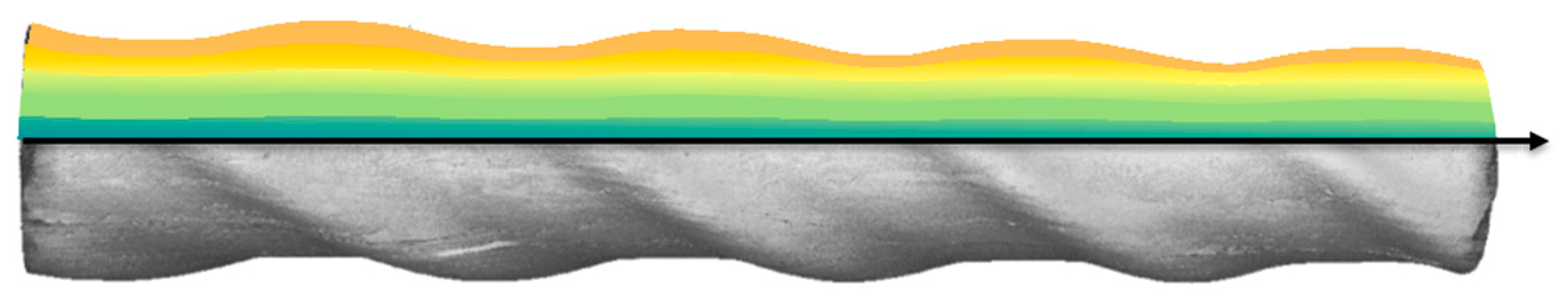
2.1. Helix-Pultruded Rebars
2.1.1. Carbon Tape Workpiece
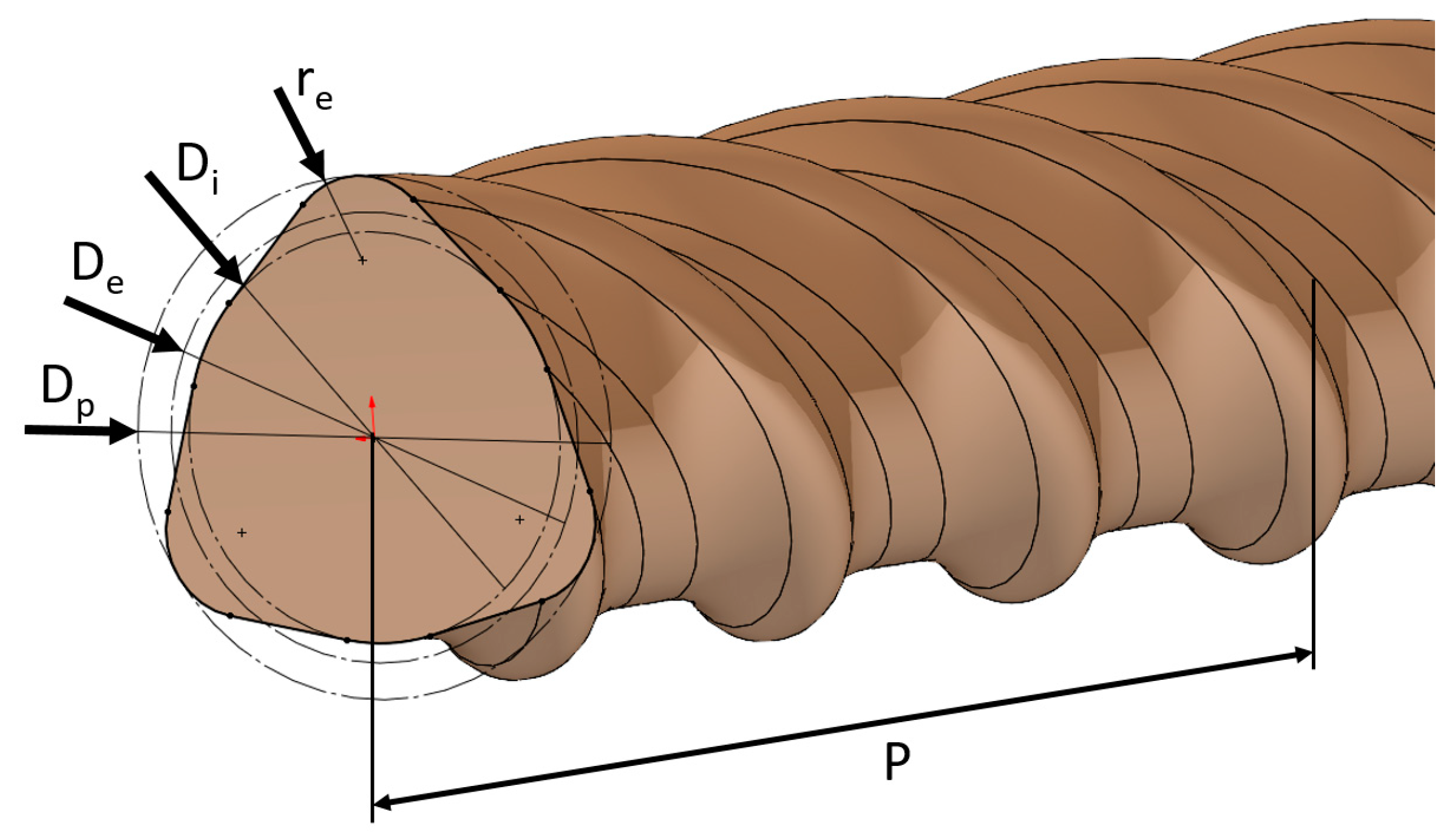
2.1.2. Helix-Pultruded Rebar Geometry Variants
- Number of helix ribs n;
- Pitch P;
- Circumferential diameter Dp;
- Equivalent diameter De;
- Projected flank area Af;
- Af/Ai.
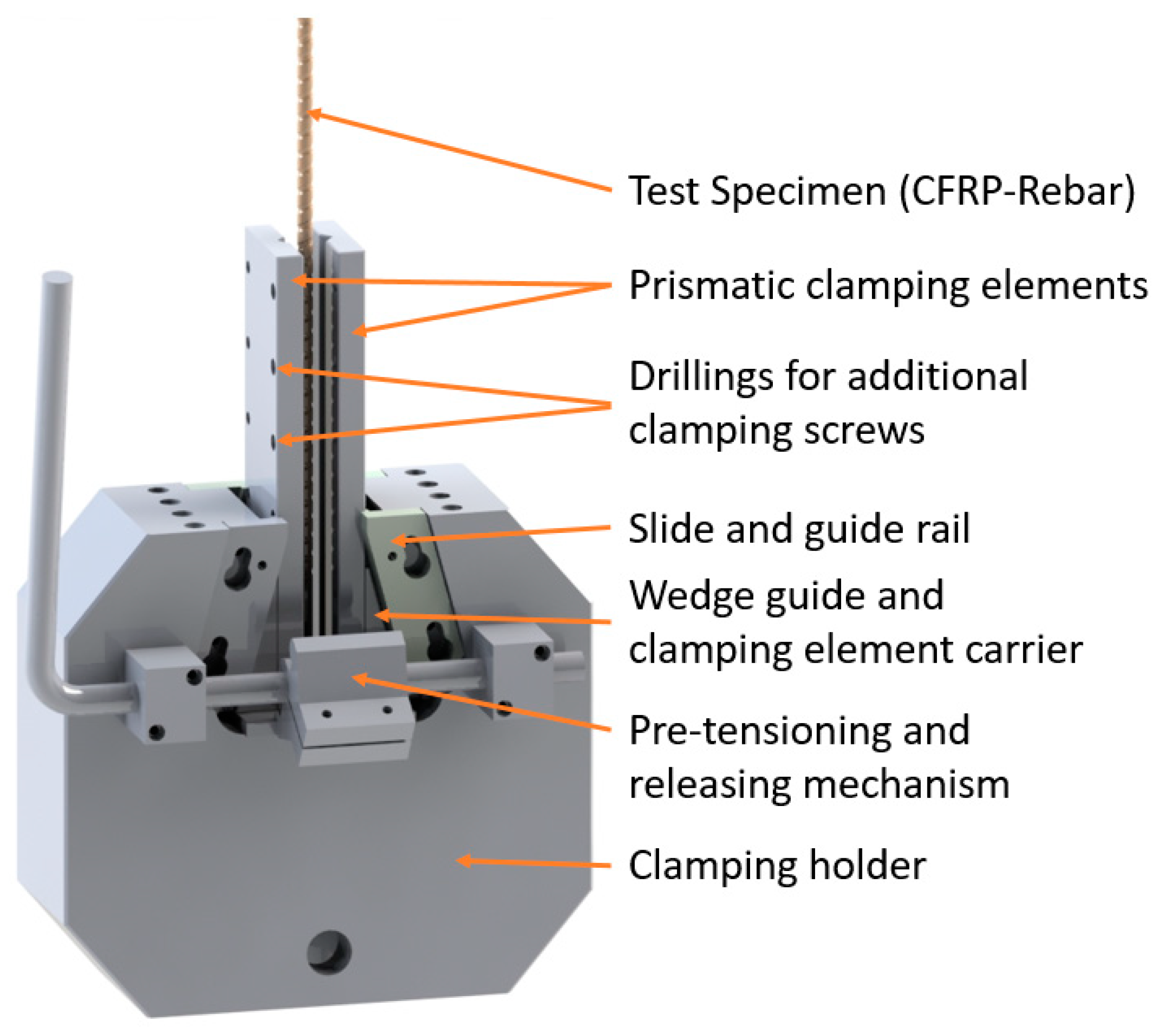
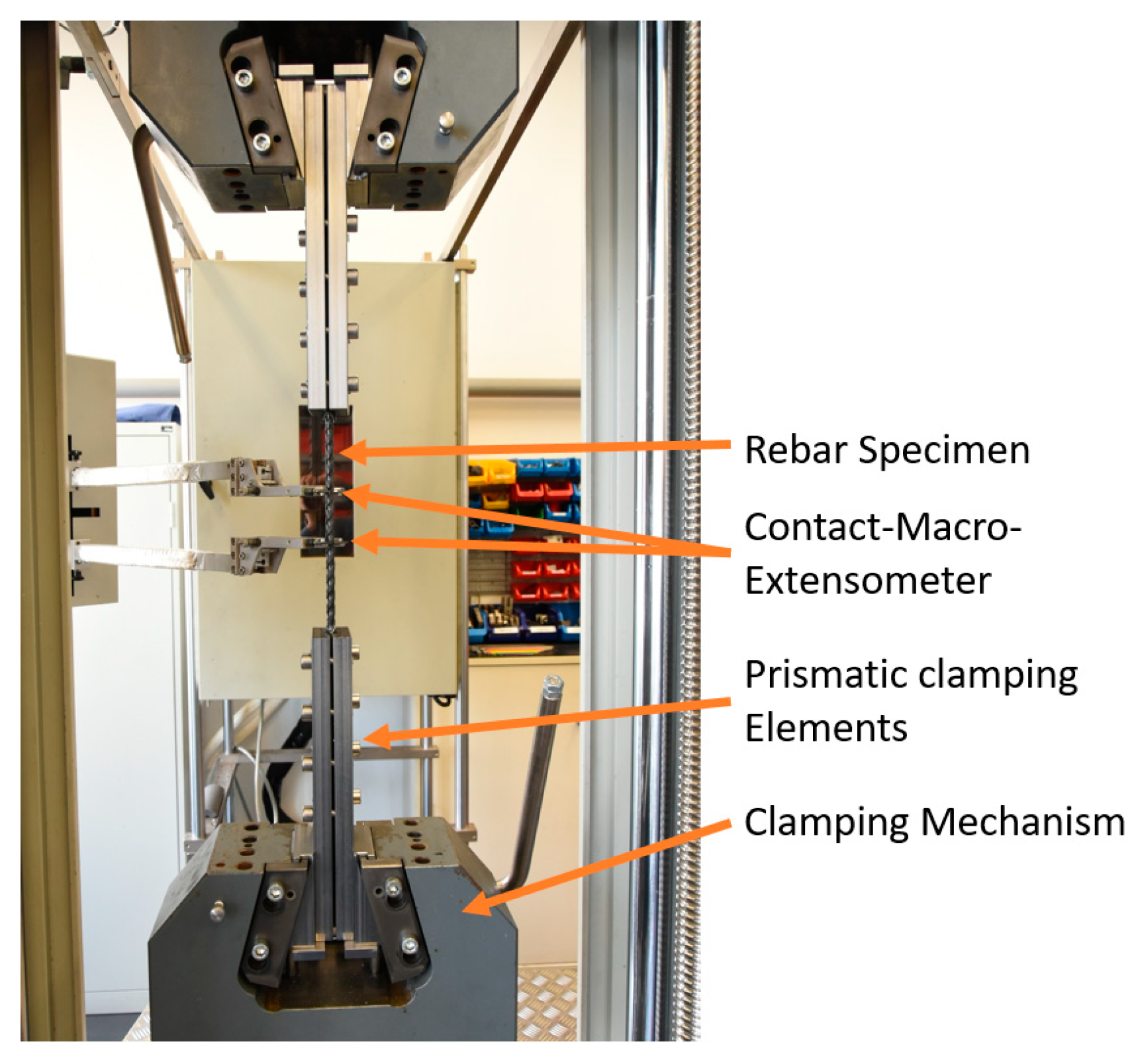
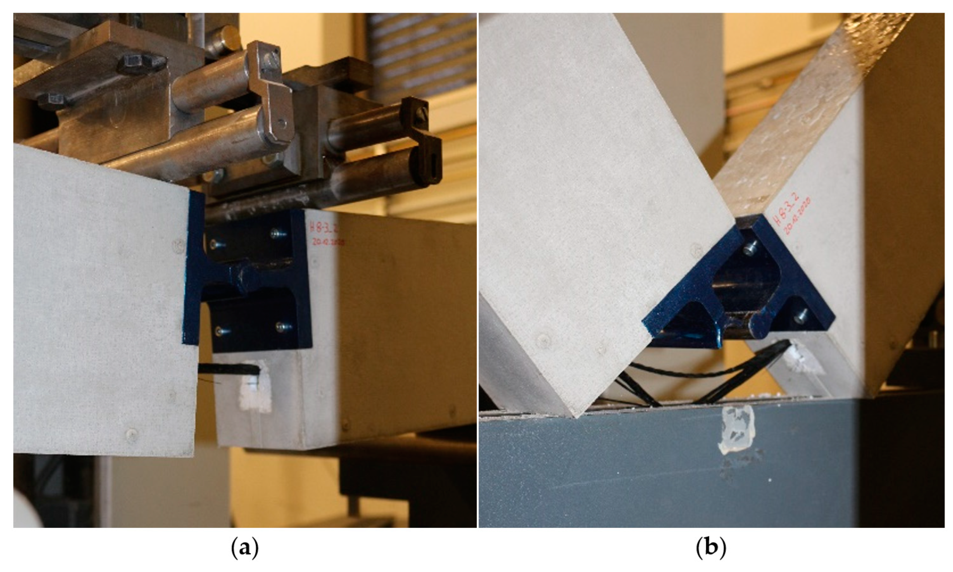
2.2. Tensile Testing of Helix-Pultruded Rebar Elements
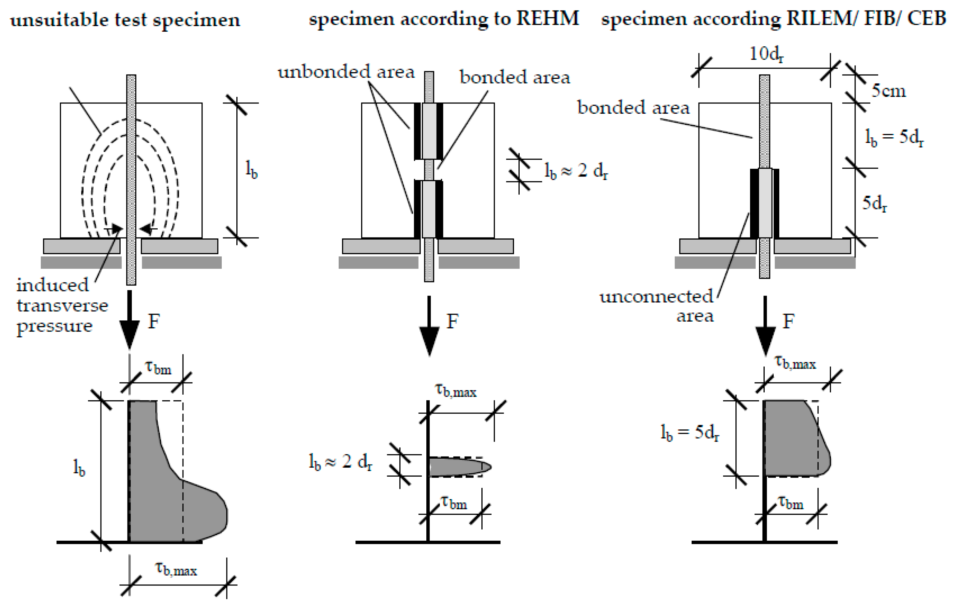
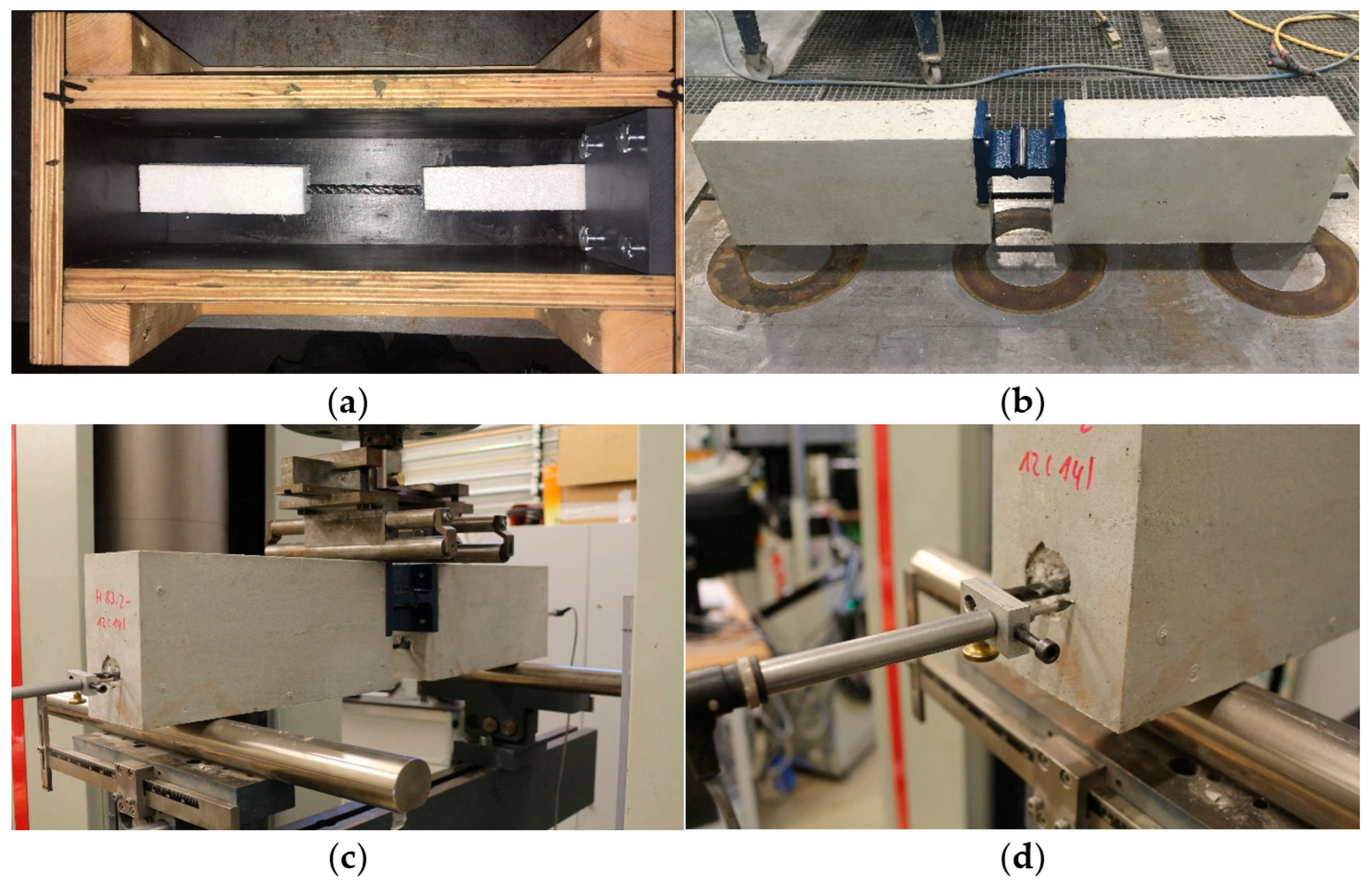
2.3. Pull-Out Testing of Helix-Pultruded Rebar Elements
3. Results
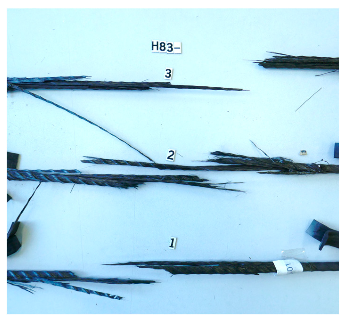
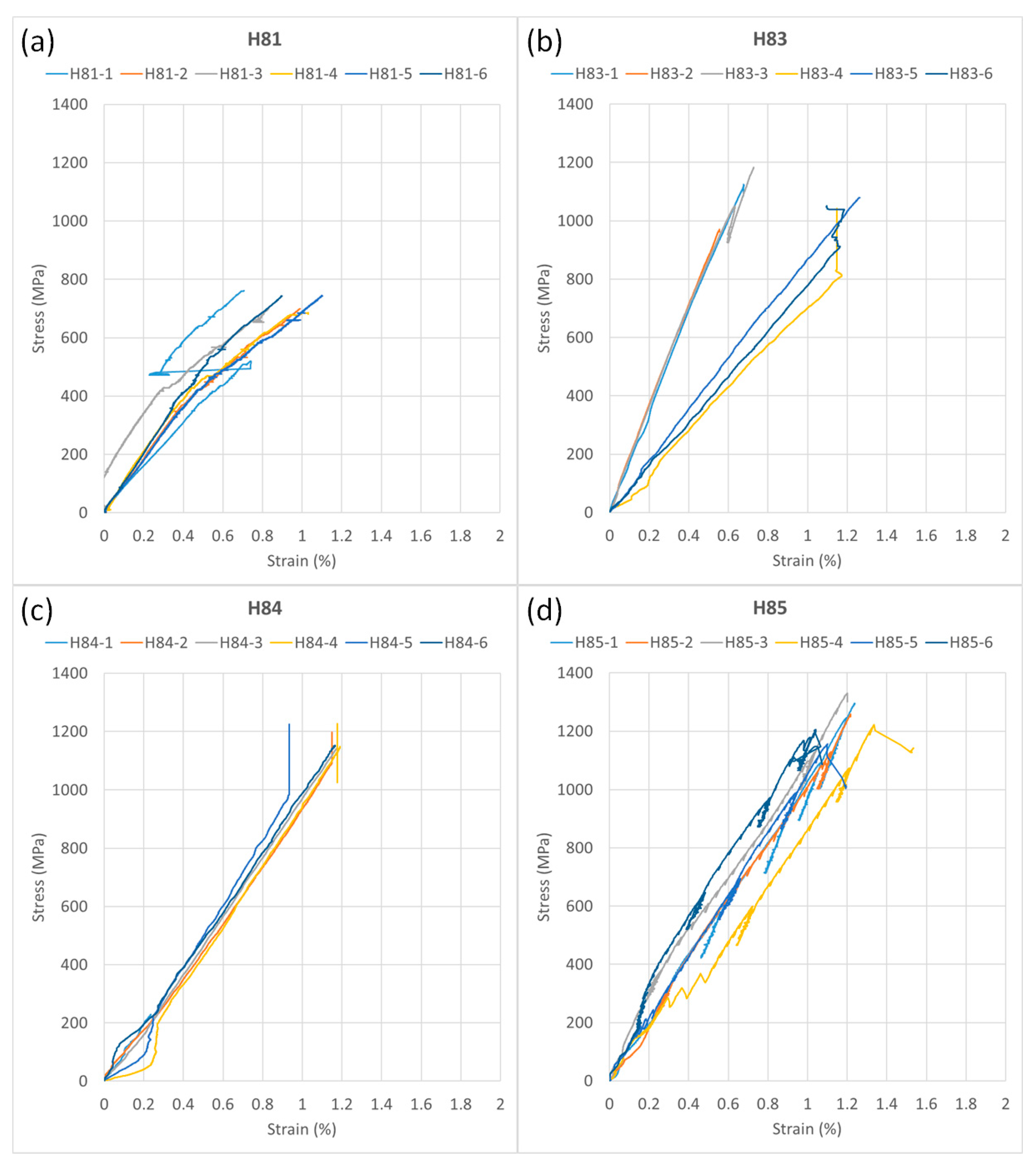
3.1. Tensile Tests
3.2. Pull-Out Tests
4. Discussion
5. Conclusions and Outlook
- Reinforcing bar structures made of fiber composites enables thinner construction methods. In particular, carbon reinforcements are corrosion-resistant and reduce the required concrete cover.
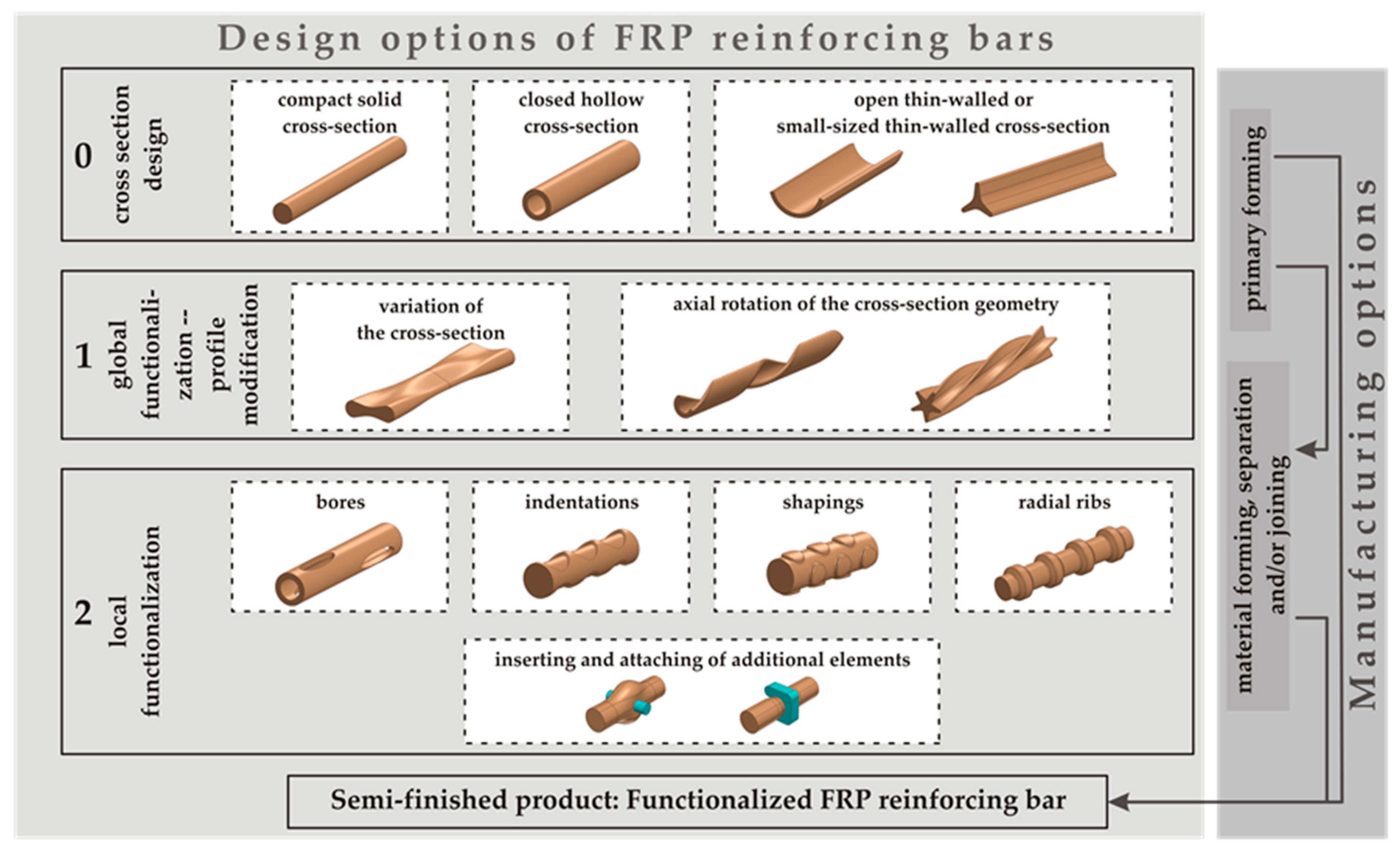
- The newly developed helix-pultrusion process enables efficient manufacturing processes for fiber-composite reinforcement bar structures. It is characterized by few process steps and the effective use of materials. During the work, design parameters were varied, and corresponding variants were manufactured to achieve a more load-oriented material arrangement and utilization.
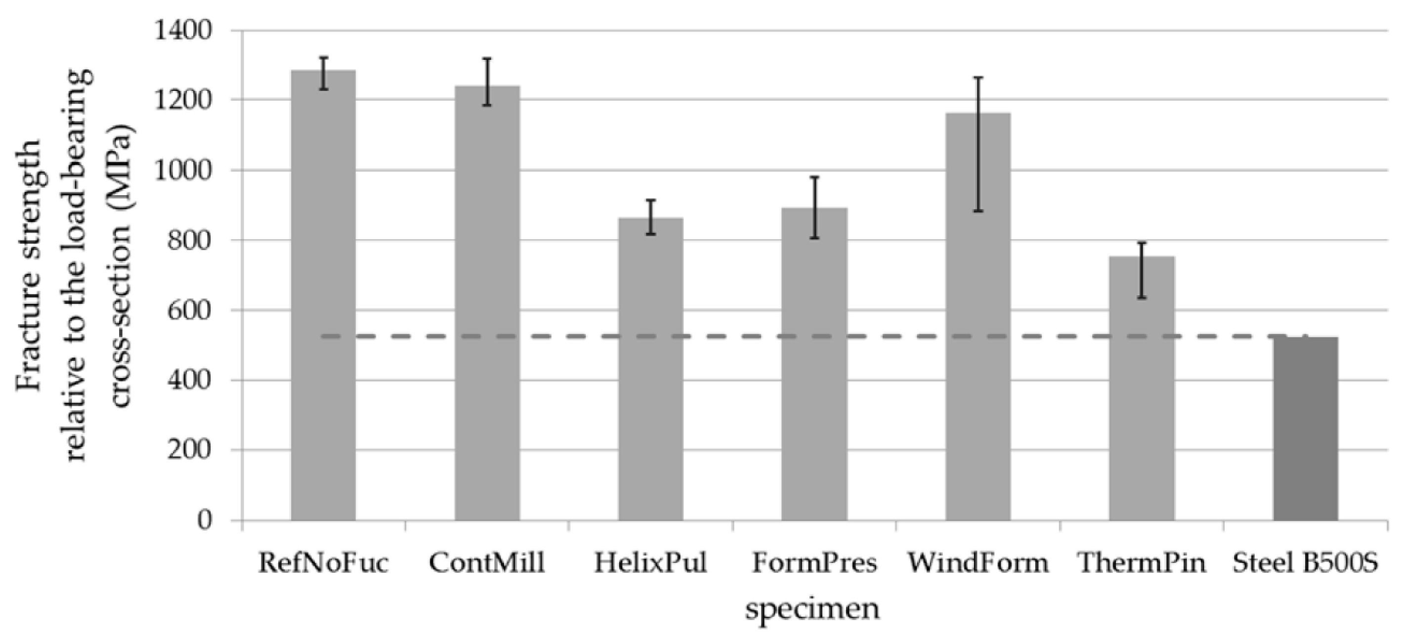
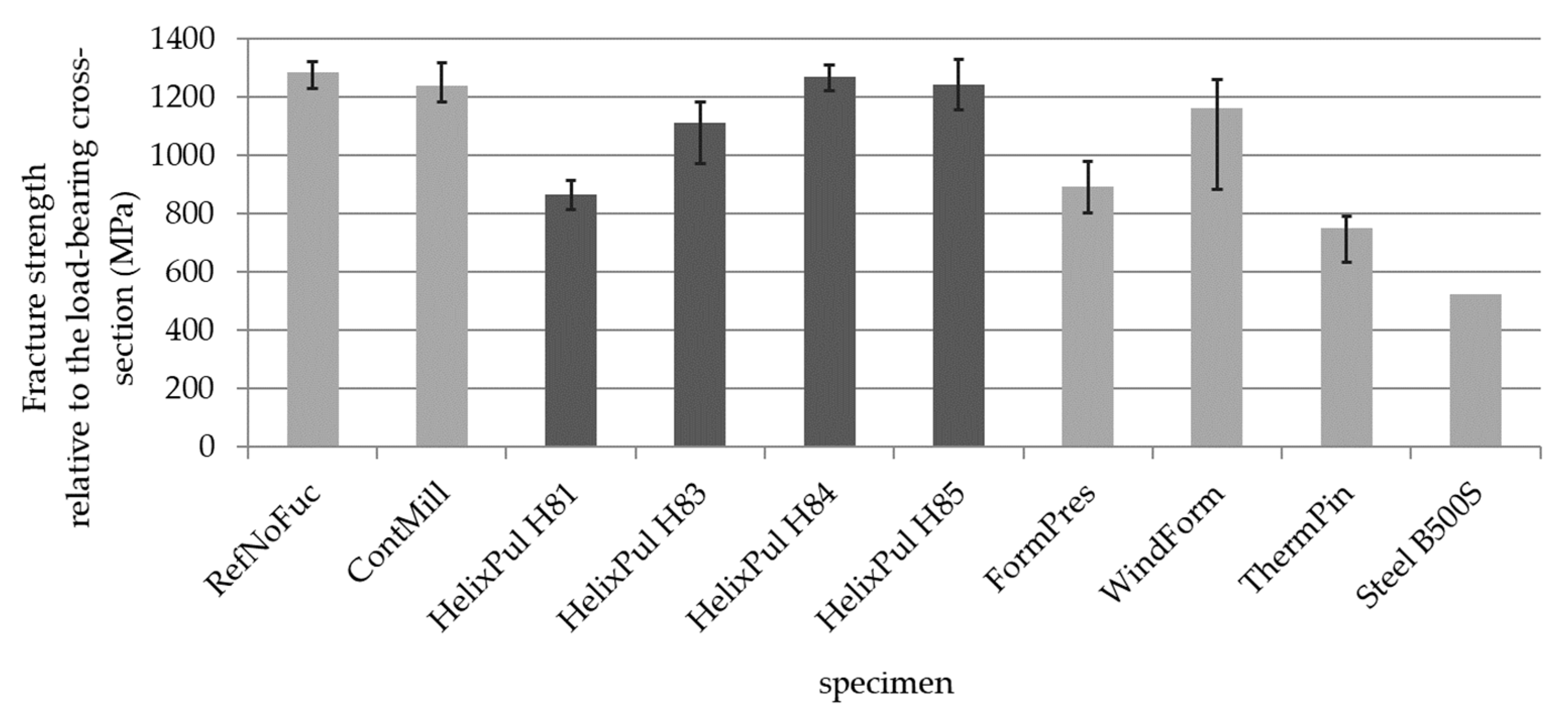
- The tensile behavior of the reinforcement bar prototypes was tested using a new, efficient tensioning system developed in-house. Compared to unfunctionalized reference bars, similar bar tensile strength was achieved with the contour adjustments, and the manufacturing influence of helix pultrusion was almost eliminated. The fracture strength of the HelixPul rebars was increased by more than 40% on average.
- By employing a more complex test arrangement, it was possible to determine torsional moment-free and transverse force-free pull-out characteristics, demonstrating good comparative pull-out behavior. The tensile force transmission in the composite for the HelixPul rebars was increased by more than a factor of 2.5.
- The determined preferred helix rebar contour, HelixPul H85, proves the suitability of these reinforcing bars from the novel production technology, due to element tension tests and concrete pull-out tests.
Author Contributions
Funding
Data Availability Statement
Acknowledgments
Conflicts of Interest
References
- European Commission. European Climate Law. In Official Journal of the European Union; European Commission: Luxemburg, 2021. [Google Scholar]
- Scheerer, S.; Schladitz, F.; Curbach, M. Textile reinforced concrete—From the idea to a high performance material. In Proceedings of the FERRO-11 and 3rd ICTRC in Aachen, Aachen, Germany, 7–10 June 2015; Rilem Publications S.A.R.L.: Bagneux, France, 2015. [Google Scholar]
- Schladitz, F.; Curbach, M.; Tietze, M.; Lieboldt, M. Carbon and Concrete—The Future of Construction. IABSE Symp. Rep. 2016, 106, 733–743. [Google Scholar] [CrossRef]
- Maslyk, M.; Gäb, T.; Matveeva, G.; Opitz, P.; Mondeshki, M.; Krysiak, Y.; Kolb, U.; Tremel, W. Multistep Crystallization Pathways in the Ambient-Temperature Synthesis of a New Alkali-Activated Binder. Adv. Funct. Mater. 2022, 32, 2108126. [Google Scholar] [CrossRef]
- Hawkins, P.; Tennis, P.D.; Detwiler, R.J. The Use of Limestone in Portland Cement: A State-of-the-Art Review, EB227; Portland Cement Association: Skokie, IL, USA, 2005; 44p. [Google Scholar]
- Liu, B.; Qin, J.; Shi, J.; Jiang, J.; Wu, X.; He, Z. New perspectives on utilization of CO2 sequestration technologies in cement-based materials. Constr. Build. Mater. 2021, 272, 121660. [Google Scholar] [CrossRef]
- Kahnt, A.; Schladitz, F.; Tietze, M.; Scheerer, S.; Curbach, M. Carbon concrete—A high-performance material with great efficiency potential. Detail 2016, 4, 302–308. [Google Scholar]
- Kahnt, A.; Schladitz, F.; Tietze, M.; Lieboldt, M.; Curbach, M. C3-carbonbeton—Eine Materialkombination für die Zukunft des Bauens. BWI BetonWerk Int. 2016, 6, 22–28. [Google Scholar]
- Rademacher, T.; Wände, H. Available online: https://elements.evonik.de/wp-content/uploads/2021/08/EVMAG_0221_DE_1019_Beton_DataMining_Protectosil-geloest-1.pdf (accessed on 23 March 2023).
- UN Envireoment Programme. The Search for Sustainable Sand Extraction is Beginning. Available online: https://www.unep.org/news-and-stories/story/search-sustainable-sand-extraction-beginning (accessed on 24 February 2023).
- World Economic Forum. Sand mining: The Environmental Challenge You’ve Probably Never Heard Of. Available online: https://www.weforum.org/agenda/2022/06/global-sand-mining-demand-impacting-environment/ (accessed on 24 February 2023).
- Quarryingafrica. Is Manufactured Sand the Material of the Future? Available online: https://quarryingafrica.com/5935-2/?utm_source=rss&utm_medium=rss&utm_campaign=5935-2 (accessed on 28 February 2023).
- Sand, Kies und Phosphat aus dem Meer. Available online: https://worldoceanreview.com/de/wor-3/mineralische-rohstoffe/vorkommen-und-maerkte/sand-kies-und-phosphat-aus-dem-meer/ (accessed on 28 February 2023).
- Nawy, E.G. Concrete Construction Engineering Handbook, 2nd ed.; CRC Press: Boca Raton, FL, USA, 2008; pp. 1–21–1–26. [Google Scholar]
- Yun, H.-D.; Kim, S.-H.; Choi, W. Determination of Mechanical Properties of Sand-Coated Carbon Fiber Reinforced Polymer (CFRP) Rebar. Polymers 2023, 15, 2186. [Google Scholar] [CrossRef] [PubMed]
- Schneider, K.; Butler, M.; Mechtcherine, V. Carbon concrete composites C3—Nachhaltige Bindemittel und Betone für die Zukunft. In Beton-und Stahlbetonbau; Wiley Online Library: New York, NY, USA, 2017; p. 112. [Google Scholar]
- Mechtcherine, V. Towards a durability framework for structural elements and structures made of or strengthened with high-performance fibre-reinforced composites. Constr. Build. Mater. 2012, 31, 94–104. [Google Scholar] [CrossRef]
- Rempel, S.; Will, N.; Hegger, J.; Beul, P. Filigrane bauwerke aus textilbeton. In Beton-und Stahlbetonbau Spezial; Wiley Online Library: New York, NY, USA, 2015; Volume 110, pp. 83–93. [Google Scholar]
- Böhm, R.; Thieme, M.; Wohlfahrt, D.; Wolz, D.S.; Richter, B.; Jäger, H. Reinforcement Systems for Carbon Concrete Composites Based on Low-Cost Carbon Fibers. Fibers 2018, 6, 56. [Google Scholar] [CrossRef] [Green Version]
- Mostert, C.; Bock, J.; Sameer, H.; Bringezu, S. Environmental Assessment of Carbon Concrete Based on Life-Cycle Wide Climate, Material, Energy and Water Footprints. Materials 2022, 15, 4855. [Google Scholar] [CrossRef] [PubMed]
- Spelter, A.; Rempel, S.; Will, N.; Hegger, J. Prüfkonzept zur Untersuchung des Dauerstandsverhaltens von textilbewehrtem Beton. Bauingenieur 2017, 92, 364–369. [Google Scholar]
- Tietze, M.; Schladitz, F.; Kahnt, A.; Curbach, M. Modular building solutions with carbon reinforced concrete. In Proceedings of the IABSE Conference—Bridges and Structures Sustainability—Seeking Intelligent Solutions, Guangzhou, China, 8–11 May 2016; IABSE: Guangzhou, China, 2016. [Google Scholar]
- Thieme, M.; Wohlfahrt, D.; Böhm, R.; Gude, M. Design and manufacturing of novel thermoplastic CFRP rods for carbon concrete composites. In Proceedings of the 18th European Conference on Composite Materials, Athens, Greece, 24–28 June 2018. [Google Scholar]
- Kraft, R.; Kahnt, A.; Grauer, O.; Thieme, M.; Wolz, D.S.; Schlüter, D.; Tietze, M.; Curbach, M.; Holschemacher, K.; Jäger, H.; et al. Advanced Carbon Reinforced Concrete Technologies for Façade Elements of Nearly Zero-Energy Buildings. Materials 2022, 15, 1619. [Google Scholar] [CrossRef]
- Vedernikov, A.; Safonov, A.; Tucci, F.; Carlone, P.; Akhatov, I. Pultruded materials and structures: A review. J. Compos. Mater. 2020, 54, 4081–4117. [Google Scholar] [CrossRef]
- Zhu, F.; Bai, P.; Lei, D. Measurement of tensile mechanical properties of fiber reinforced plastic rebars by 3D digital image correlation. Mater. Test. 2020, 4, 422–428. [Google Scholar] [CrossRef]
- Benmokrane, B.; Zhang, B.; Chennouf, A. Tensile Properties and Pull out Behaviour of AFRP and CFRP rods for grouted anchor applications. Constr. Build. Mater. 2000, 14, 157–170. [Google Scholar] [CrossRef]
- SGL Technologies GmbH—Data sheet: Unidirectional carbon fiber tape with thermoplastic matrix, status 08/2015.
- SGL Technologies GmbH—Data sheet: SIGRAFIL Carbon-Endlosfasern, Status 02/2016. Available online: https://www.sglcarbon.com/loesungen/material/sigrafil-carbon-endlosfasern2 (accessed on 15 March 2023).
- Steel for the reinforcement and prestressing of concrete—Test methods—Part 1: Reinforcing bars, rods and wire (ISO 15630-1:2019), German version EN ISO 15630-1:2019.
- Metallic materials—Calibration and verification of static uniaxial testing machines—Part 1: Tension/compression testing machines—Calibration and verification of the force-measuring system (ISO 7500-1:2018), German version EN ISO 7500-1:2018.
- Metallic materials—Tensile testing—Part 1: Method of test at room temperature (ISO 6892-1:2019), German version EN ISO 6892-1:2019.
- Füllsack-Köditz, R. Verbundverhalten von GFK-Bewehrungsstäben und Rissentwicklung in GFK-Stabbewehrten Betonbauteilen. Ph.D. Dissertation, Bauhaus-Universität Weimar, Weimar, Germany, 2004. [Google Scholar]
- RILEM TC. RILEM Recommendations for the Testing and Use of Constructions Materials; E & FN SPON: London, UK, 1994; pp. 213–217. [Google Scholar] [CrossRef]
- Rehm, G. Über die Grundlagen des Verbundes zwischen Stahl und Beton; journal 138; Ernst&Sohn; Deutscher Ausschuss für Stahlbeton: Berlin, Germany, 1961. [Google Scholar]
- Carvalho, E.; Ferreira, E.; Cunha, J.; Rodrigues, C.; Maia, N. Experimental Investigation of Steel-Concrete Bond for Thin Reinforcing Bars. Lat. Am. J. Solids Struct. 2017, 14, 1932–1951. [Google Scholar] [CrossRef] [Green Version]


| Functionalization | Abbreviation | Design Example |
|---|---|---|
| Reference (no functionalization) | RefNoFuc |  |
| Winding-forming by means of semi-finished tape | WindForm |  |
| Contour milling of functionalization | ContMill |  |
| Form-pressing of functionalization | FormPres |  |
| Primary forming only with helix pultrusion | HelixPul |  |
| Out-displacing and penetrating cylindrical elements | ThermPin |  |
| Property | Measured Values (FVR = 0.45) | Data Sheet SGL CF-PA6_Tape * (FVR = 0.5) | Mixing Rule with Fiber Properties by SGL ** (FVR = 0.45) |
|---|---|---|---|
| Tensile Modulus E1 | 102 GPa | 115 GPa | 108 GPa |
| Tensile Strength Ftu;1 | 1290 MPa | 1800 MPa | 1800 MPa |
| Elongation at Break A1 | 1.17% | 1.48% | --- |
| Tensile Modulus E2 | 101.6 GPa | --- | --- |
| Tensile Strength Ftu;2 | 1290 MPa | --- | --- |
| Elongation at Break A2 | 3.05% | --- | --- |
| Compressive Strength Rs;1 | 403 MPa | --- | --- |
| Compressive Strength Rs;2 | 114.2 MPa | --- | --- |
| Shear Strength S12 | 64.2 MPa | --- | --- |
| Design Variant | H81 | H82 | H83 | H84 | H85 |
|---|---|---|---|---|---|
| Geometry |  |  |  |  |  |
| Number of Helix Ribs n | 3 | 3 | 3 | 6 | 2 |
| Pitch P | 30 mm | 60 mm | 30 mm | 30 mm | 30 mm |
| Inner Circle Diameter Di | 7.3 mm | 7.3 mm | 7.3 mm | 7.3 mm | 7.3 mm |
| Perimeter Diameter Dp | 9.3 mm | 9.3 mm | 8.3 mm | 7.97 mm | 8.5 mm |
| Equivalent Diameter De | 8.0 mm | 8.0 mm | 7.57 mm | 7.60 mm | 7.97 mm |
| Projected Flank Area Af | 26.08 mm2 | 26.08 mm2 | 12.25 mm2 | 8.04 mm2 | 14.89 mm2 |
| Af/Ai | 0.62 | 0.62 | 0.29 | 0.19 | 0.36 |
| Variant | Fmax (kN) | σmax (MPa) | εmax* (%) | |
|---|---|---|---|---|
| H81 n = 6 | 36.3 | 867.2 | 0.932 | |
| s | 1.6 | 38.4 | 0.134 | |
| ν [%] | 4.43 | 4.42 | 14.36 | |
| H83 n = 6 | 46.5 | 1111.8 | 0.912 | |
| s | 3.1 | 73.5 | 0.294 | |
| ν [%] | 6.63 | 6.61 | 32.21 | |
| H84 n = 6 | 53.2 | 1270.8 | 1.068 | |
| s | 1.6 | 38.1 | 0.163 | |
| ν [%] | 3 | 3 | 15.27 | |
| H85 n = 6 | 52.1 | 1245.2 | 1.19 | |
| s | 2.6 | 63.1 | 0.106 | |
| ν [%] | 5.06 | 5.07 | 8.94 |
| Variant | Fmax (kN) | kmax (N/mm) | |
|---|---|---|---|
| H81 n = 3 | 3.98 | 179.02 | |
| s | 1.09 | 24.05 | |
| ν (%) | 27.46 | 13.43 | |
| H83 n = 4 | 9.28 | 325.57 | |
| S | 0.76 | 26.82 | |
| ν (%) | 8.22 | 8.33 | |
| H84 n = 3 | 7.00 | 237.19 | |
| s | 0.38 | 14.30 | |
| ν (%) | 5.49 | 6.03 |
| Variant | Fmax (kN) | ∆lmax (mm) | fmax (mm) | |
|---|---|---|---|---|
| H81 n = 3 | 8.5 | 1.81 | 10.6 | |
| s | 1.38 | 1.14 | 4.89 | |
| H83 n = 4 | 21.9 | 2.14 | 13.4 | |
| S | 0.63 | 0.44 | 0.94 | |
| H84 n = 4 | 17.7 | 2.66 | 11.9 | |
| s | 1.49 | 0.2 | 0.77 | |
| H85 n = 2 | 22.4 | 1.04 | 12.6 | |
| s | 4.63 | 0.36 | 3.1 |
| Variant (i) | = σmax (MPa) | σmax(i)/σmax (Ref) |
|---|---|---|
| RefNoFuc | 1284.8 | 100.0% |
| ContMill | 1239.8 | 96.5% |
| HelixPul H81 | 866.1 | 67.4% |
| HelixPul H83 | 1111.8 | 86.5% |
| HelixPul H84 | 1270.9 | 98.9% |
| HelixPul H85 | 1245.2 | 96.9% |
| FormPres | 895.0 | 69.7% |
| WindForm | 1163.2 | 90.5% |
| ThermPin | 753.3 | 58.6% |
Disclaimer/Publisher’s Note: The statements, opinions and data contained in all publications are solely those of the individual author(s) and contributor(s) and not of MDPI and/or the editor(s). MDPI and/or the editor(s) disclaim responsibility for any injury to people or property resulting from any ideas, methods, instructions or products referred to in the content. |
© 2023 by the authors. Licensee MDPI, Basel, Switzerland. This article is an open access article distributed under the terms and conditions of the Creative Commons Attribution (CC BY) license (https://creativecommons.org/licenses/by/4.0/).
Share and Cite
Wohlfahrt, D.; Peller, H.F.M.; Müller, S.; Modler, N.; Mechtcherine, V. Investigation of Helix-Pultruded CFRP Rebar Geometry Variants for Carbon-Reinforced Concrete Structures. Polymers 2023, 15, 3285. https://doi.org/10.3390/polym15153285
Wohlfahrt D, Peller HFM, Müller S, Modler N, Mechtcherine V. Investigation of Helix-Pultruded CFRP Rebar Geometry Variants for Carbon-Reinforced Concrete Structures. Polymers. 2023; 15(15):3285. https://doi.org/10.3390/polym15153285
Chicago/Turabian StyleWohlfahrt, Daniel, Hannes Franz Maria Peller, Steffen Müller, Niels Modler, and Viktor Mechtcherine. 2023. "Investigation of Helix-Pultruded CFRP Rebar Geometry Variants for Carbon-Reinforced Concrete Structures" Polymers 15, no. 15: 3285. https://doi.org/10.3390/polym15153285