
Study of Thermal Effect on the Mechanical Properties of Nylon 610 Nanocomposites with Graphite Flakes That Have Undergone Supercritical Water Treatment at Different Temperatures
Abstract
:1. Introduction
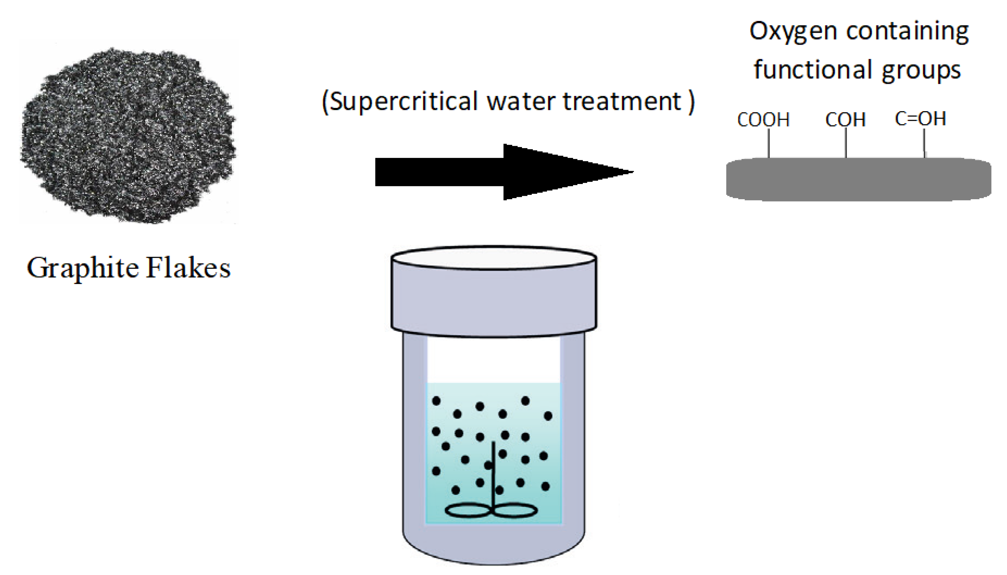
2. Materials and Methodology
2.1. Materials
2.2. Preparation of Nylon 610/Graphite Flakes Nanocomposites
2.3. Characterization Testing
2.3.1. Tensile Testing
2.3.2. X-Ray Diffraction (XRD) Analysis
2.3.3. Fourier Transform Infrared Spectroscopy (FTIR) Analysis
2.3.4. Scanning Electron Microscopy Analysis (SEM)
3. Results and Discussion
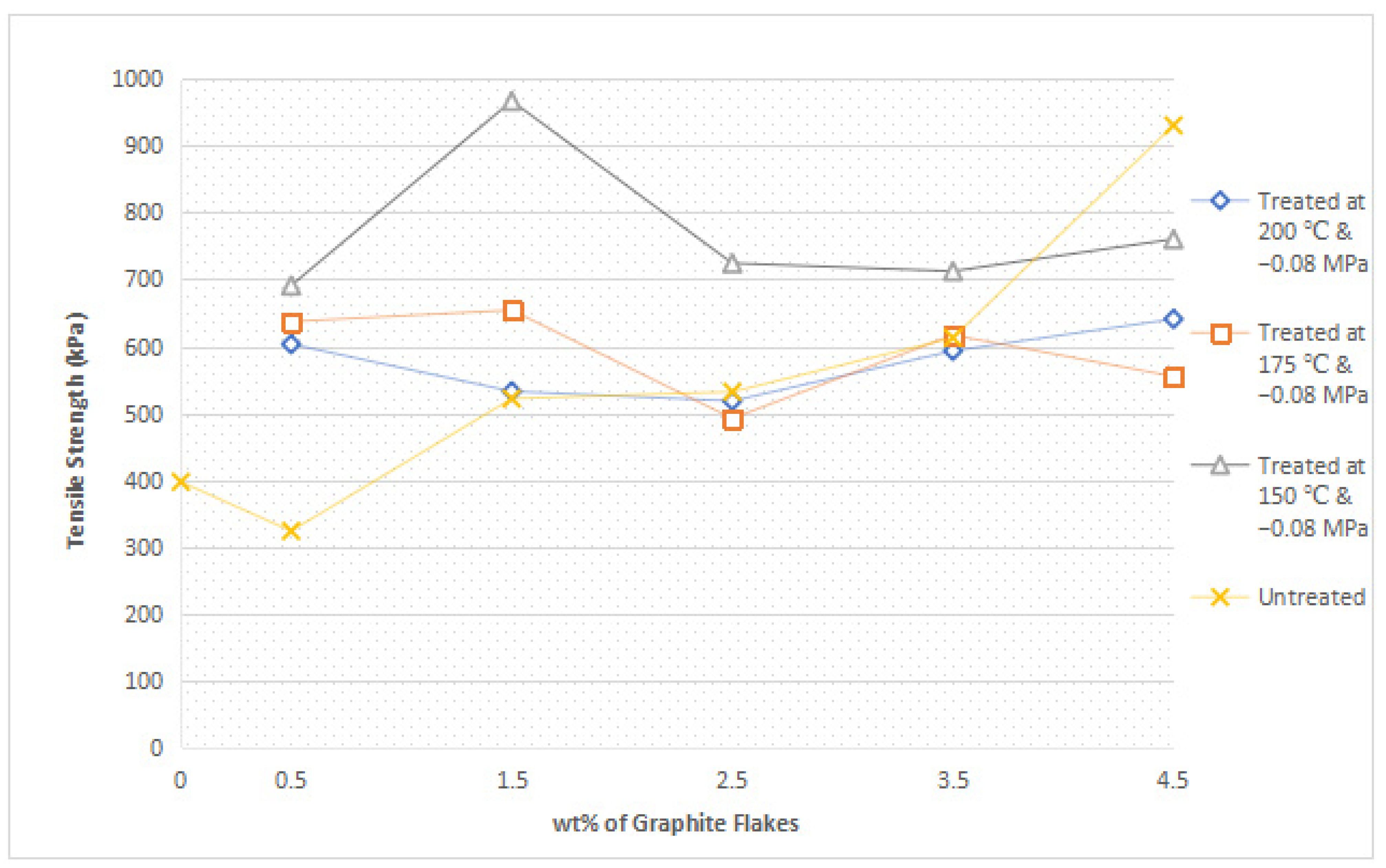
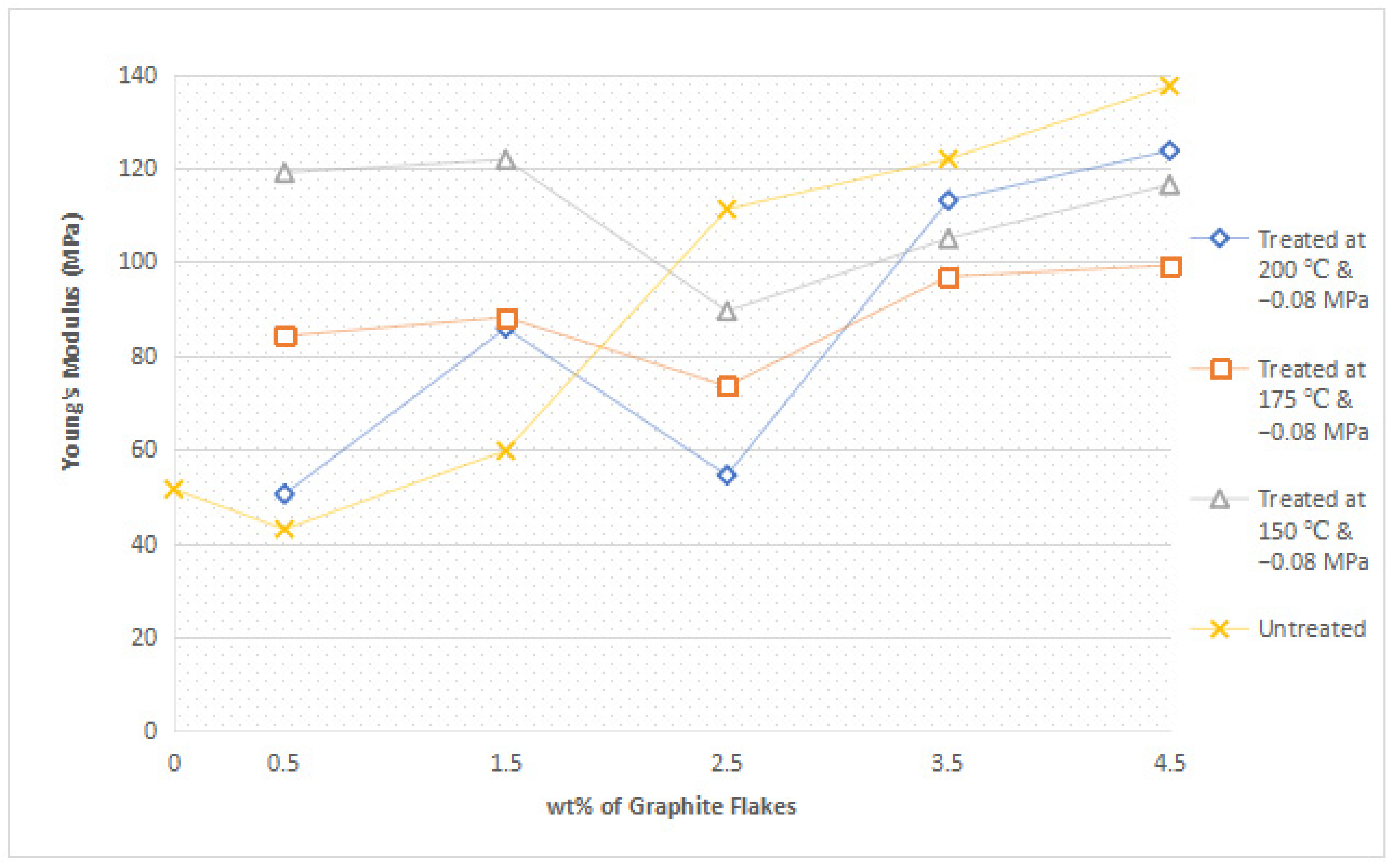
3.1. Mechanical Properties
3.1.1. Tensile Strength
3.1.2. Young’s Modulus
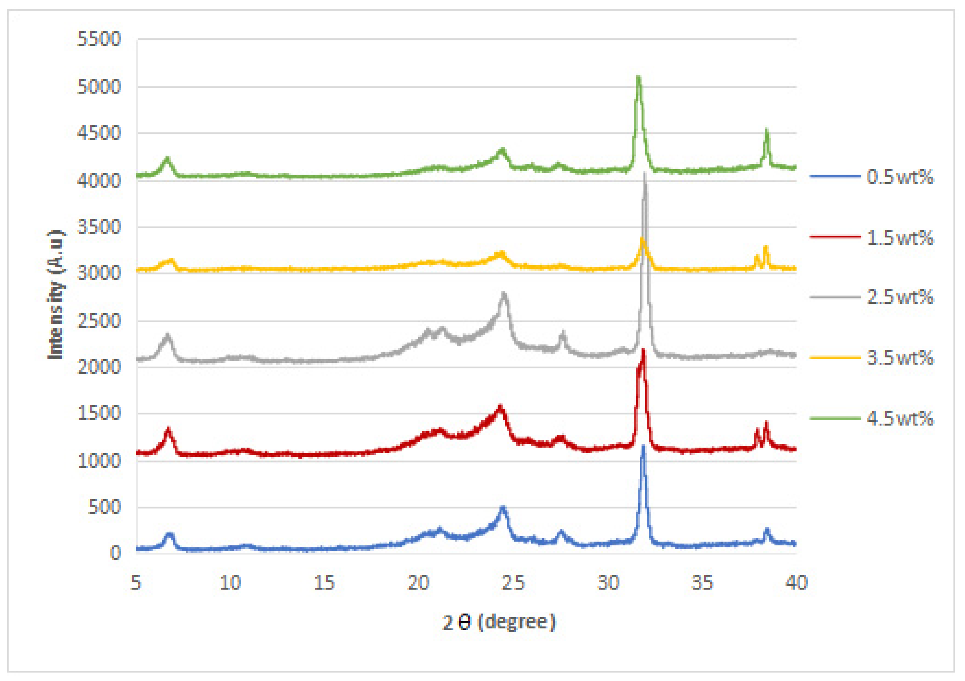
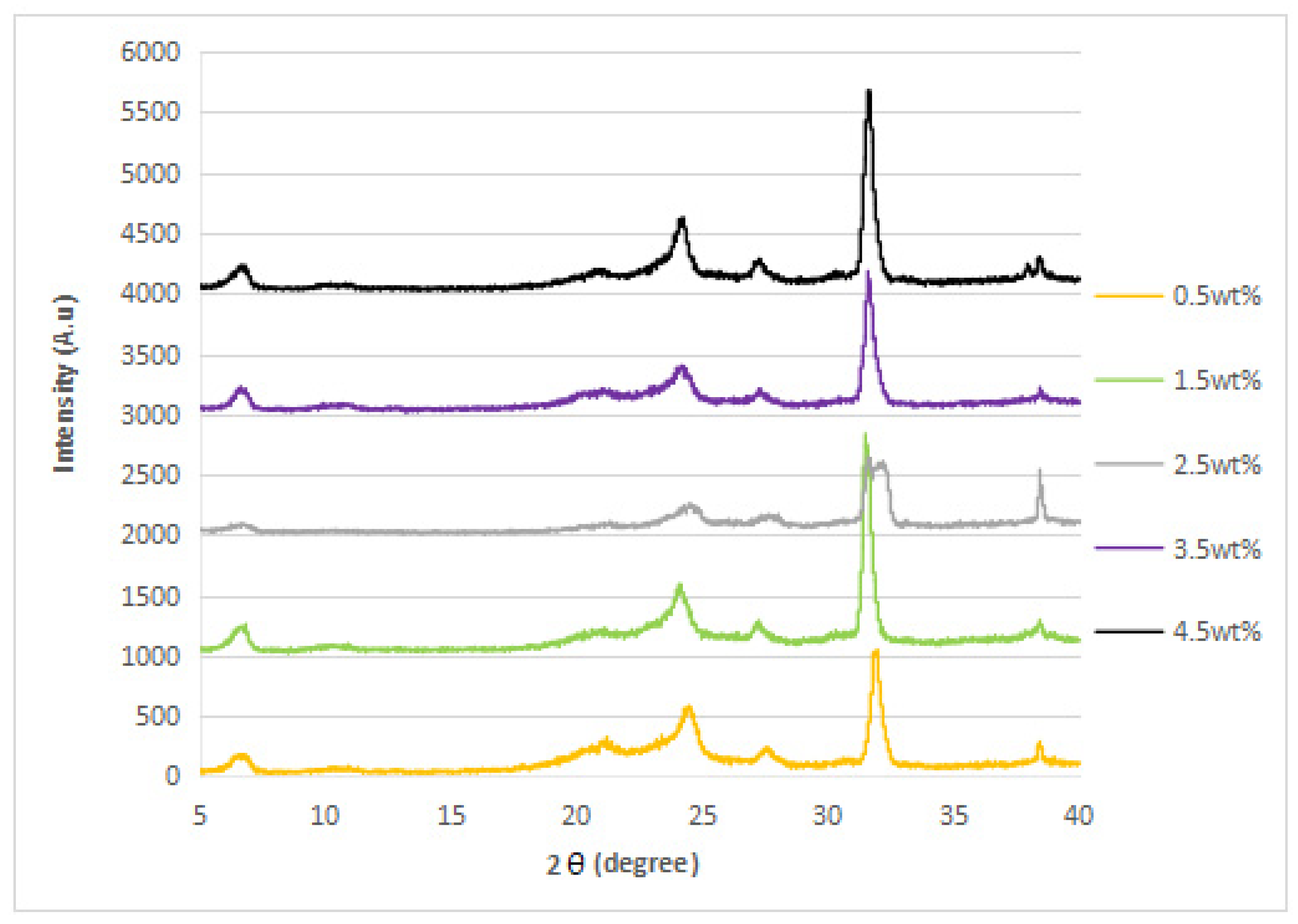
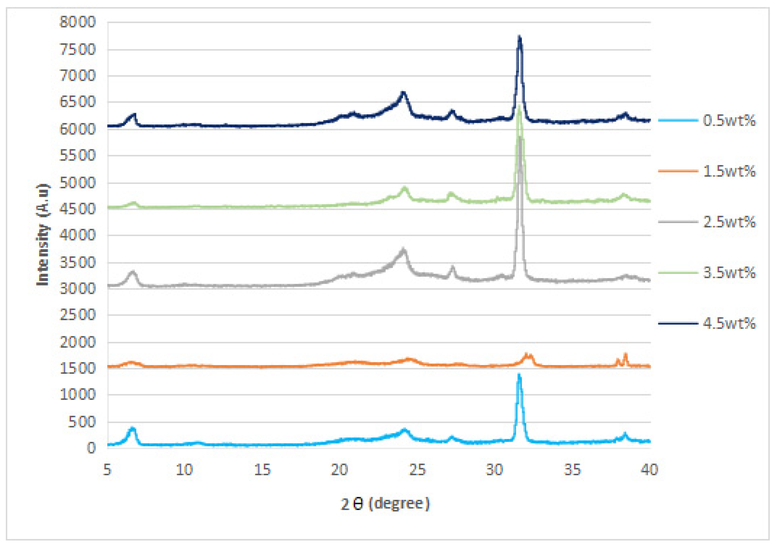
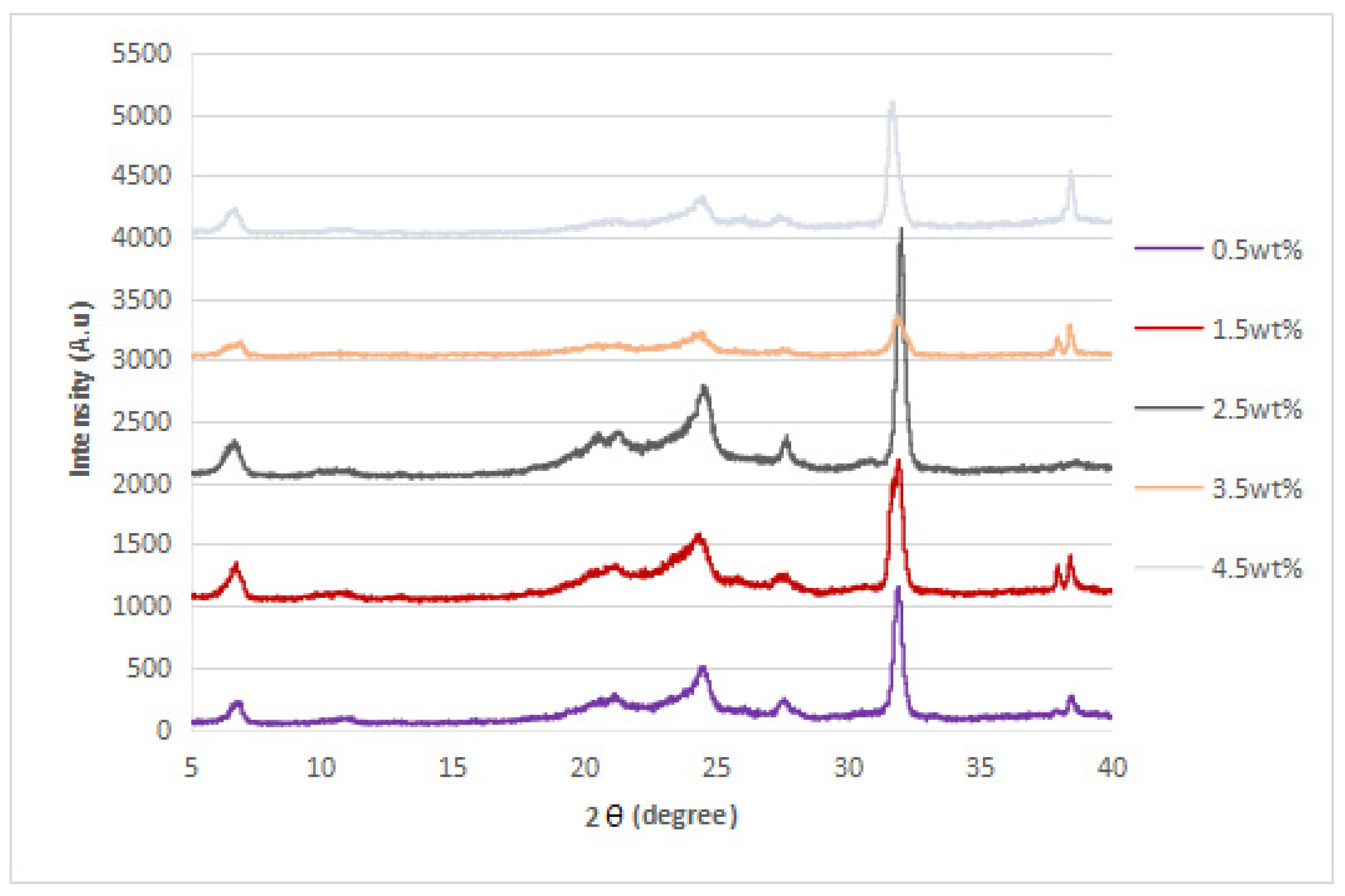
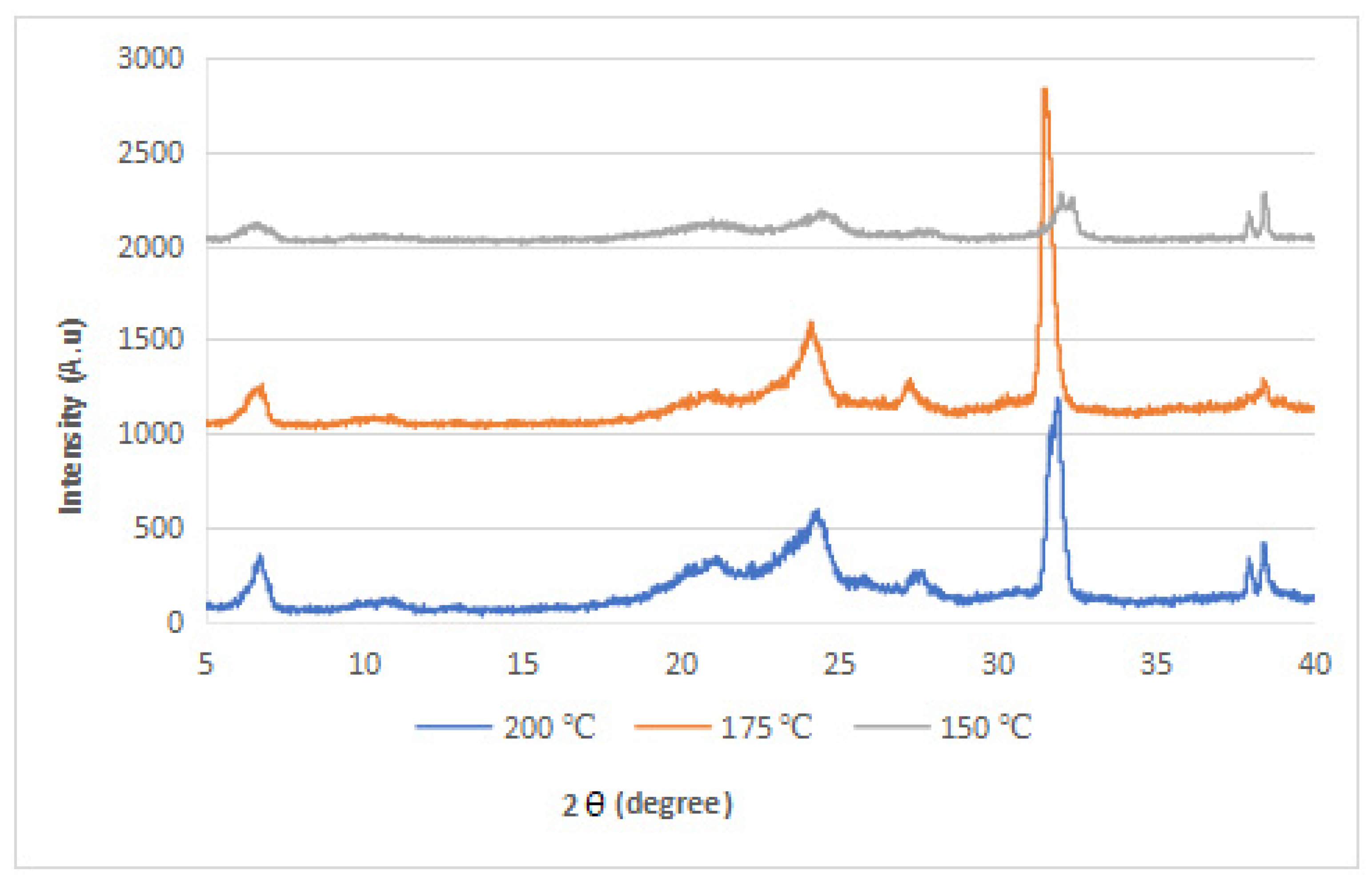
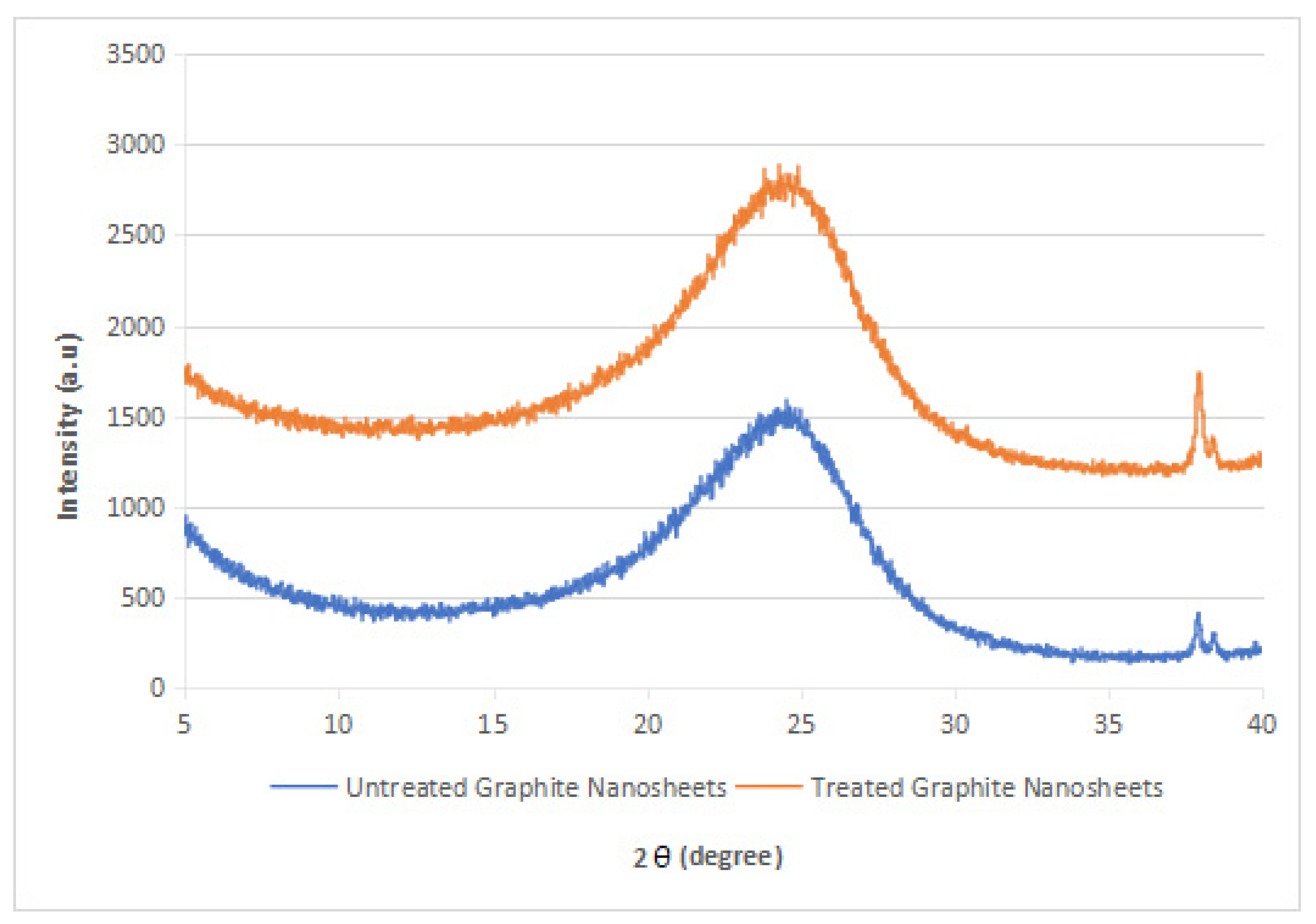
3.2. XRD Analysis
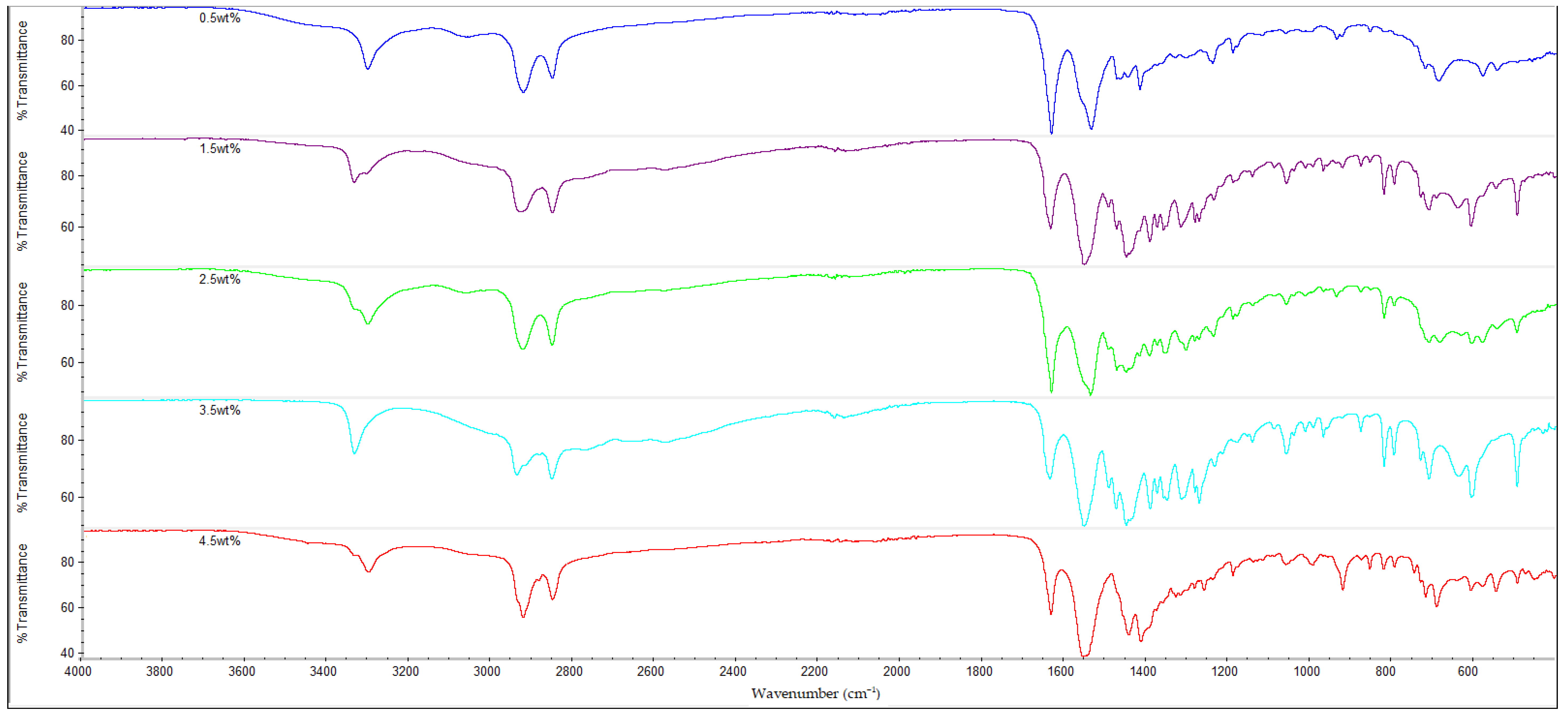
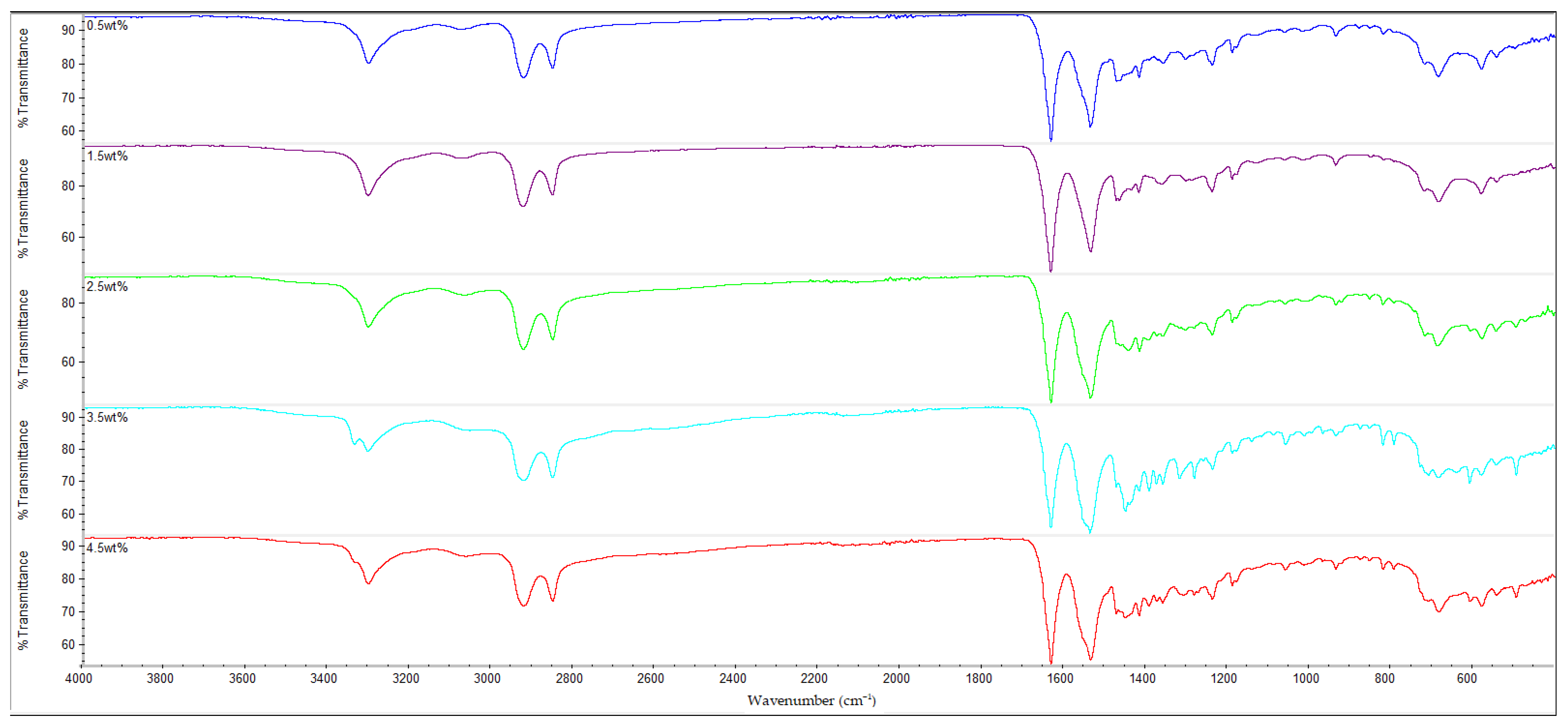
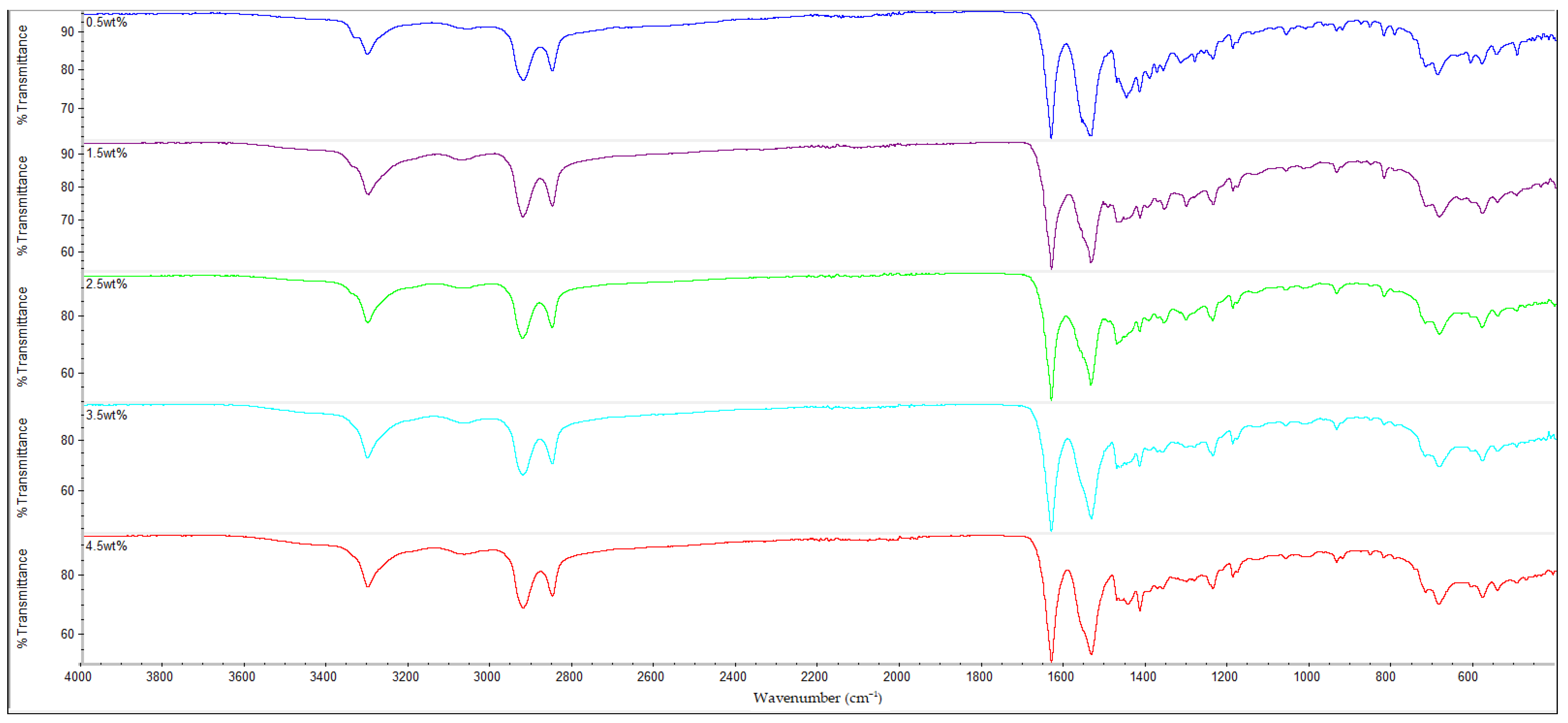
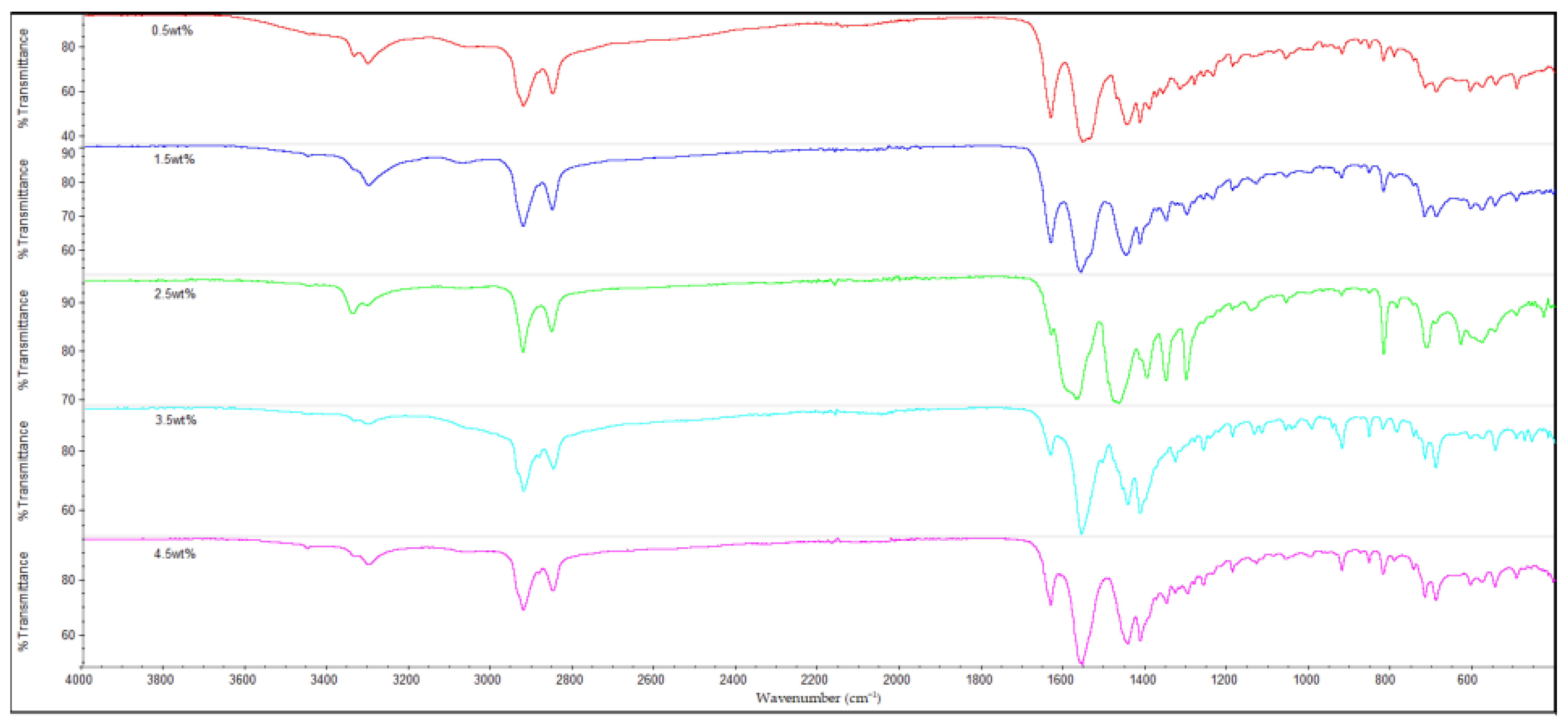
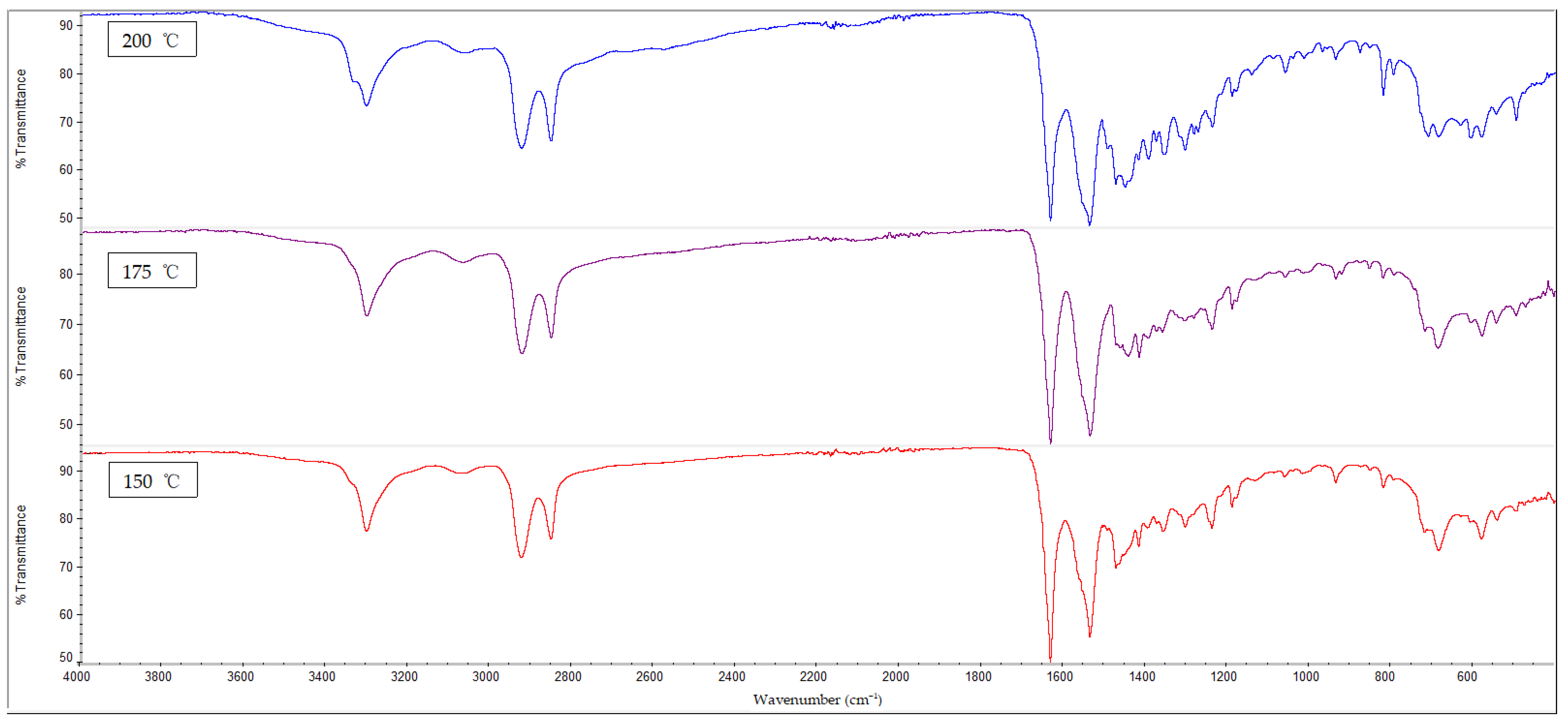
3.3. FTIR Analysis
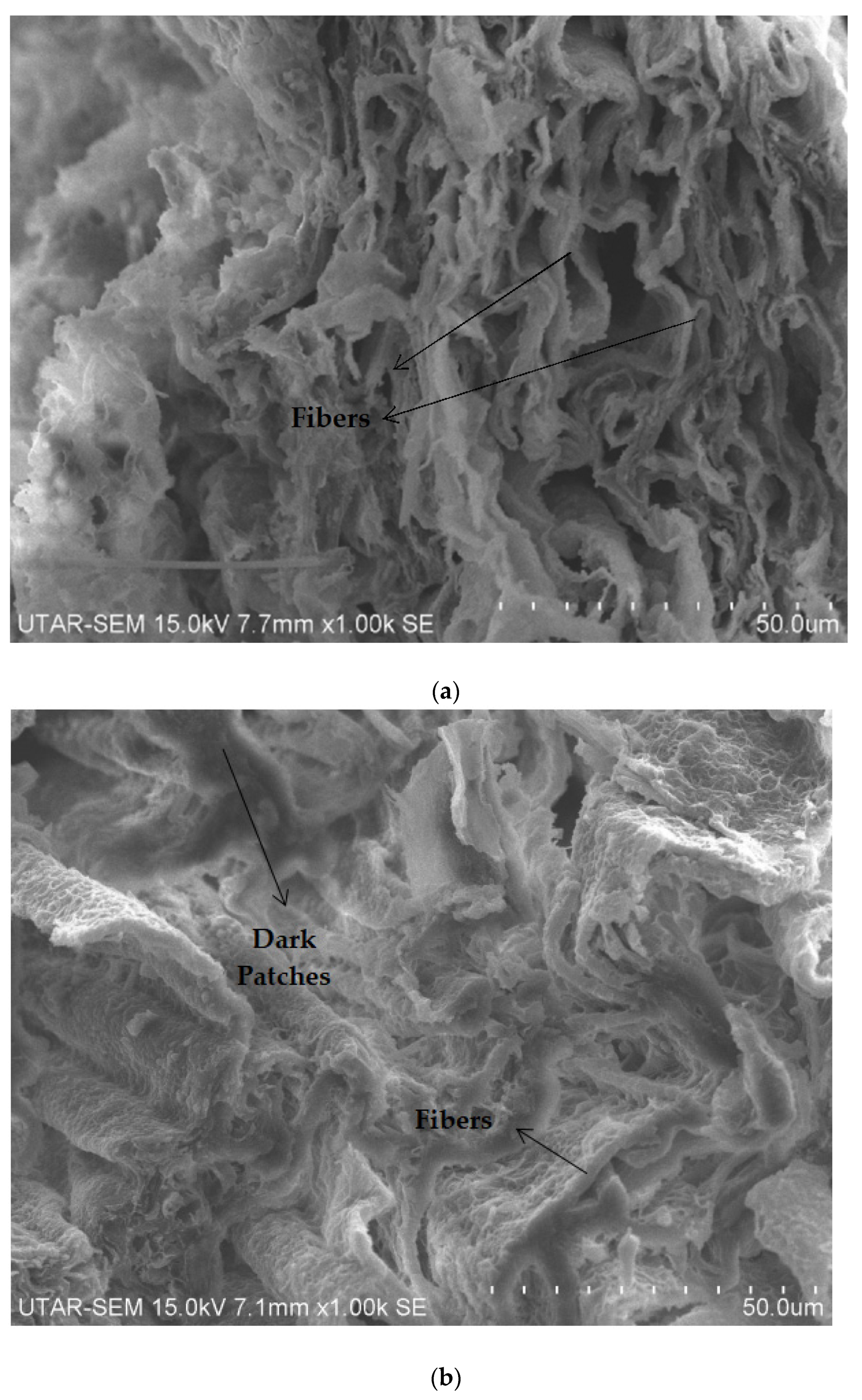
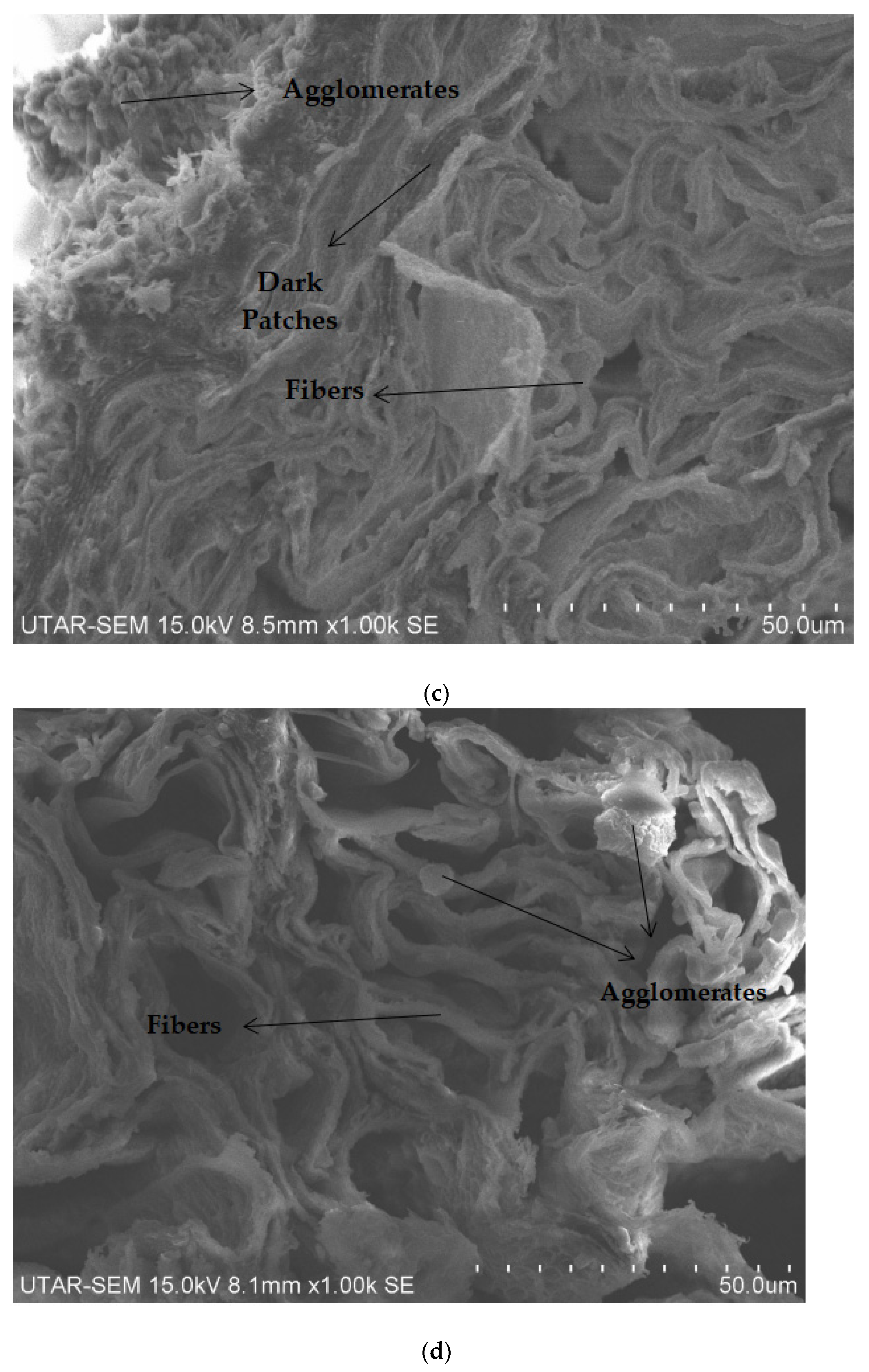
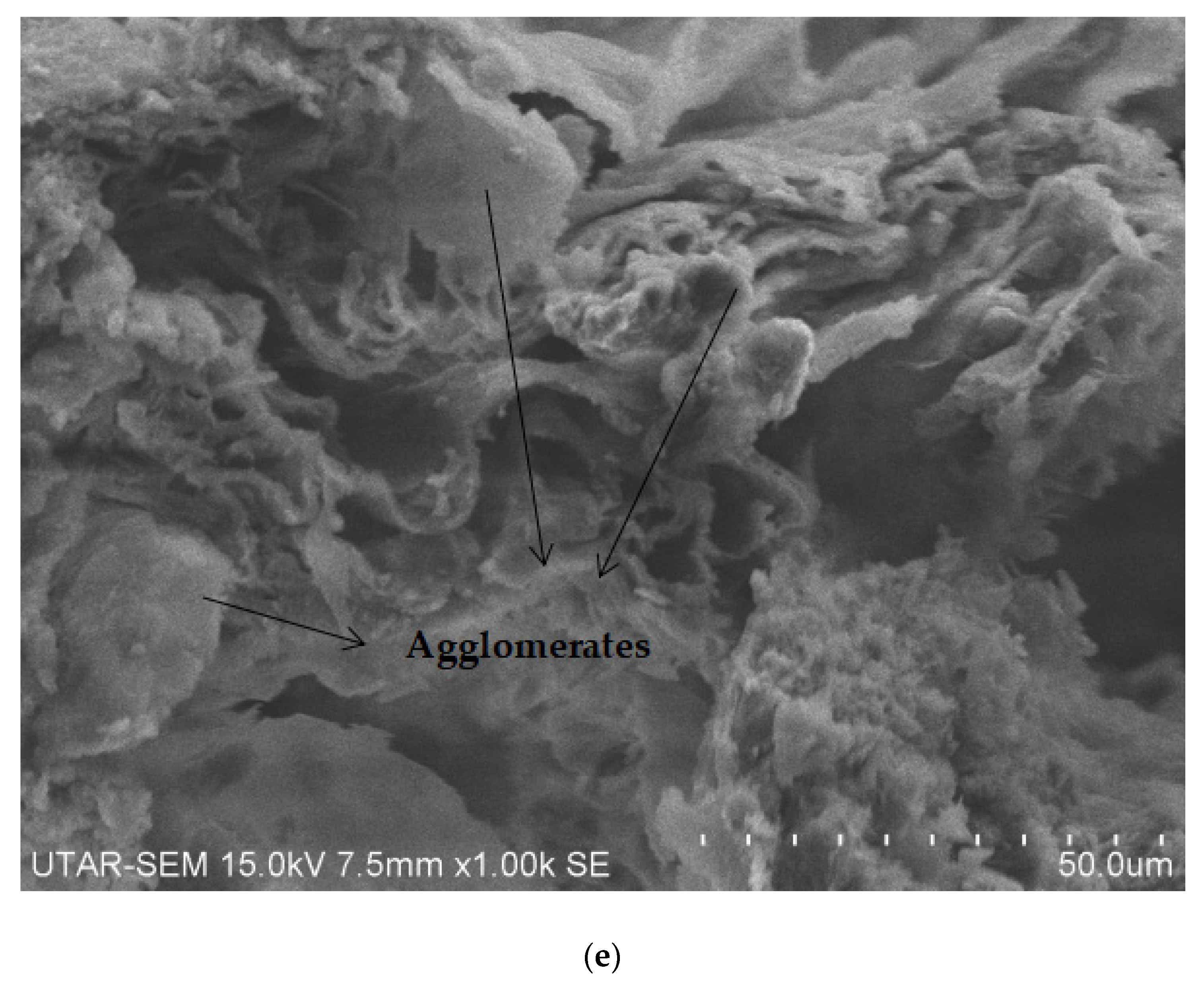
3.4. SEM Analysis
4. Conclusions
Supplementary Materials
Author Contributions
Funding
Institutional Review Board Statement
Informed Consent Statement
Data Availability Statement
Conflicts of Interest
Abbreviations
References
- Wang, X.; Bradford, P.; Liu, W.; Zhao, H.; Inoue, Y.; Maria, J.-P.; Li, Q.; Yuan, F.-G.; Zhu, Y.T. Mechanical and electrical property improvement in CNT/Nylon composites through drawing and stretching. Compos. Sci. Technol. 2011, 71, 1677–1683. [Google Scholar] [CrossRef]
- Weng, W.; Chen, G.; Wu, D. Transport properties of electrically conducting nylon 6/foliated graphite nanocomposites. Polymer. 2005, 46, 6250–6257. [Google Scholar] [CrossRef]
- Zheng, D.; Tang, G.; Zhang, H.; Yu, Z.; Yavari, F.; Koratkar, N.; Lim, S.; Lee, M. In situ thermal reduction of graphene oxide for high electrical conductivity and low percolation threshold in polyamide 6 nanocomposites. Compos. Sci. Technol. 2012, 72, 284–289. [Google Scholar] [CrossRef]
- Papageorgiou, D.G.; Kinloch, I.A.; Young, R.J. Mechanical properties of graphene and graphene-based nanocomposites. Prog. Mater. Sci. 2017, 90, 75–127. [Google Scholar] [CrossRef]
- Herrera-Ramírez, L.C.; Castell, P.; Fernández-Blázquez, J.P.; Fernández, Á.; Guzmán de Villoria, R. How do graphite nanoplates affect the fracture toughness of polypropylene composites? Compos. Sci. Technol. 2015, 111, 9–16. [Google Scholar] [CrossRef]
- Wang, A.J.; Duan, Y.Z.; Gu, X.Y.; Zhang, S.; Zang, W.H. Surface modification of polyamide66 fabric by grafting with vinyltrimethoxysilane. Chem. Res. Chin. Univ. 2017, 33, 492–498. [Google Scholar] [CrossRef]
- Neves, J.C.; Castro, V.G.D.; Assis, A.L.S.; Veiga, A.G.; Rocco, M.L.M.; Silva, G.G. In-situ determination of amine/epoxy and carboxylic/epoxy exothermic heat of reaction on surface of modified carbon nanotubes and structural verification of covalent bond formation. Appl. Surf. Sci. 2017, 436, 495–504. [Google Scholar] [CrossRef]
- Shen, J.F.; Huang, W.S.; Wu, L.P.; Hu, Y.Z.; Ye, M.X. Study on amino-functionalized multiwalled carbon nanotubes. Mat. Sci. Eng.-A Struct. 2007, 464, 151–156. [Google Scholar] [CrossRef]
- Kritzer, P. Corrosion in high-temperature and supercritical water and aqueous solutions: A review. J. Supercrit. Fluids 2014, 29, 1–29. [Google Scholar] [CrossRef]
- Salavagione, H.J.; Ellis, G.; Martínez, G. Graphene-Based Polymer Nanocomposites. In Physics and Applications of Graphene—Experiments; Mikhailov, S., Ed.; IntechOpen: Rijeka, Croatia, 2011; pp. 169–192. [Google Scholar]
- Hiemenz, P.C.; Lodge, T.P. Light Scattering by Polymer Solutions. In Polymer Chemistry, 2nd ed.; CRC Press: Boca Rotan, FL, USA, 2007; pp. 289–325. [Google Scholar]
- Huang, Q.; Sun, H.; Peng, T. The influence of temperature and oxidation time on the preparation of graphite oxide. Adv. Mat. Res. 2011, 366, 291–295. [Google Scholar] [CrossRef]
- Zhang, J.; Gao, X.; Yu, W.; Liu, H.; Wang, X.; Zhang, X. Polyamide 66 fibers synergistically reinforced with functionalized graphene and multi-walled carbon nanotubes. Mater. Chem. Phys. 2021, 271, 124898. [Google Scholar] [CrossRef]
- Liew, K.M.; Kai, M.F.; Zhang, L.W. Carbon nanotube reinforced cementitious composites: An overview. Compos. Part A Appl. Sci. Manuf. 2016, 91, 301–323. [Google Scholar] [CrossRef]
- Wang, Z.; Li, S.C.; Wu, Z.J. The fabrication and properties of a graphite nanosheet/polystyrene composite based on graphite nanosheets treated with supercritical water. Compos. Sci. Technol. 2015, 112, 50–57. [Google Scholar] [CrossRef]
- Stankovich, S.; Dikin, D.A.; Dommett, G.H.B.; Kohlhaas, K.M.; Zimney, E.J.; Stach, E.A.; Piner, R.D.; Nguyen, S.T.; Ruoff, R.S. Graphene-based composite materials. Nature 2006, 442, 282–286. [Google Scholar] [CrossRef]
- Moniruzzaman, M.; Chattopadhyay, J.; Billups, W.; Winey, K. Tuning the Mechanical Properties of SWNT/Nylon 6,10 Composites with Flexible Spacers at the Interface. Nano Lett. 2007, 7, 1178–1185. [Google Scholar] [CrossRef]
- Kang, M.; Myung, S.J.; Jin, H.-J. Nylon 610 and carbon nanotube composite by in situ interfacial polymerization. Polymer 2006, 47, 3961–3966. [Google Scholar] [CrossRef]
- Kaynak, C.; Sankal, S. Effects of oxidative functionalized and aminosilanized carbon nanotubes on the crystallization behaviour of polyamide-6 nanocomposites. Polym. Bull. 2014, 71, 855–873. [Google Scholar] [CrossRef]
- Bee, S.-T.; Ooi Ker Qi, N.; Sin, L.T.; Ng, H.-M.; Lim, J.-V.; Ratnam, C.T.; Ma, C. Superior Interaction of Electron Beam Irradiation with Carbon Nanotubes Added Polyvinyl Alcohol Composite System. Polymers 2021, 13, 4334. [Google Scholar] [CrossRef]
- Rosehr, A.; Luinstra, G.A. Polypropylene composites with finely dispersed multi-walled carbon nanotubes covered with an aluminum oxide shell. Polymer 2017, 120, 164–175. [Google Scholar] [CrossRef]
- Li, J.; Li, M.; Da, H.; Liu, Q.; Liu, M. Preparation of Nylon-6/flake graphite derivatives composites with antistatic property and thermal stability. Compos. Part A Appl. Sci. Manuf. 2012, 43, 1038–1043. [Google Scholar] [CrossRef]
- Li, J.; Li, J.H.; Li, M. Ultrasound irradiation prepare sulfur-free and lower exfoliate-temperature expandable graphite. Mater Lett. 2008, 62, 2047–2049. [Google Scholar] [CrossRef]
- Aravind, K.U.; Rajendra, G.; Prakash, S.T.; Shivraj, J. Mechanical Characterisation of Polyamide 66/Graphite Nanocomposites. Int. J. Mater. Sci. 2017, 12, 411–420. [Google Scholar]
- Huang, H.-H.; De Silva, K.; Kumara, G.; Yoshimura, M. Structural evolution of hydrothermally derived reduced graphene oxide. Sci. Rep. 2018, 8, 6849. [Google Scholar] [CrossRef] [Green Version]
- Bee, S.-T.; Ratnam, C.T.; Sin, L.T.; Tee, T.T.; Hui, D.; Kadhum, A.A.H.; Rahmat, A.R.; Lau, J. Effects of electron beam irradiation on mechanical properties and nanostructural-morpholgy of montmorillonite added polyvinyl alcohol composite. Compos. B Eng. 2014, 63, 141–153. [Google Scholar] [CrossRef]
- Gupta, B.; Panda, K.; Kanan, V.; Joshi, S.; Visoly-Fisher, I. Role of oxygen functional groups in reduced graphene oxide for lubrication. Sci. Rep. 2017, 7, 45030. [Google Scholar] [CrossRef] [Green Version]
- Wang, X.D.; Liu, X.H.; Yuan, H.Y.; Liu, H.; Liu, C.T.; Li, T.X.; Yan, C.; Yan, X.R.; Shen, C.Y.; Guo, Z.H. Non-covalently functionalized graphene strengthened poly (vinyl alcohol). Mater. Des. 2018, 139, 372–379. [Google Scholar] [CrossRef]
- Ndesendo, V.M.K.; Choonara, Y.E.; Meyer, L.; Kumar, P.; Tomar, L.; Tyagi, C.; Toit, L.C.; Pillay, V. In vivo evaluation of a mucoadhesive polymeric caplet for intravaginal anti-HIV-1 delivery and development of a molecular mechanistic model for thermochemical characterization. Drug Dev. Ind. Pharm. 2014, 28, 1–14. [Google Scholar] [CrossRef]
- Chung, Y.M.; Kamal, M.R. Morphology of PA-6 vibration welded joints and its effect on weld strength. Polym. Eng. Sci. 2008, 48, 240–248. [Google Scholar] [CrossRef]
- Li, L.; Yang, G. Variable-temperature FTIR studies on thermal stability of hydrogen bonding in nylon 6/mesoporous silica nanocomposite. Polym. Int. 2009, 58, 503–510. [Google Scholar] [CrossRef]
- Lu, Y.; Zhang, Y.; Zhang, G.; Yang, M.; Yan, S.; Shen, D. Influence of thermal processing on the perfection of crystals in polyamide 66 and polyamide 66/clay composites. Polymer 2004, 45, 8999–9009. [Google Scholar] [CrossRef]
- Sin, L.T.; Bee, S.T.; Tee, T.T.; Kadhum, A.A.H.; Ma, C.; Rahmat, A.R.; Veerasamy, P. Characterization of a-tocopherol as interacting agent in polyvinyl alcohol-starch blends. Carbohydr. Polym. 2013, 98, 1281–1287. [Google Scholar] [CrossRef] [PubMed]


| Type of Nanofiller Incorporated in Nanocomposite | Loading Levels of Nanofiller (wt%) | Average Tensile Strength (kPa) | Average Young’s Modulus (MPa) |
|---|---|---|---|
| Treated Graphite Flakes at 200 °C and −0.08 MPa | 0.5 | 603.14 | 50.431 |
| 1.5 | 532.55 | 85.799 | |
| 2.5 | 518.18 | 54.442 | |
| 3.5 | 593.15 | 113.05 | |
| 4.5 | 640.76 | 123.67 | |
| Treated Graphite Flakes at 175 °C and −0.08 MPa | 0.5 | 636.98 | 84.136 |
| 1.5 | 654.05 | 88.105 | |
| 2.5 | 492.09 | 73.471 | |
| 3.5 | 616.763 | 96.827 | |
| 4.5 | 554.90 | 99.176 | |
| Treated Graphite Flakes at 150 °C and −0.08 MPa | 0.5 | 690.87 | 118.96 |
| 1.5 | 967.023 | 121.78 | |
| 2.5 | 724.27 | 89.467 | |
| 3.5 | 712.40 | 104.94 | |
| 4.5 | 760.30 | 116.42 | |
| Untreated Graphite Flakes | 0 | 397.08 | 51.465 |
| 0.5 | 323.54 | 42.934 | |
| 1.5 | 521.75 | 59.661 | |
| 2.5 | 531.81 | 111.18 | |
| 3.5 | 612.65 | 121.87 | |
| 4.5 | 930.50 | 137.44 |
| Neat Nylon 610 Synthesis Method | Average Tensile Strength (MPa) | Ref. |
|---|---|---|
| Interfacial Polymerization with No Added Heat Treatment | 0.397 | This Research |
| Interfacial Polymerization with Added Heat Treatment via Melt Extrusion | 79 | Moniruzzaman et al. [17] |
| Interfacial Polymerization with Added Heat Treatment via Hot Pressing | 35.9 | Kang et al. [18] |
| Type of Nanofiller Incorporated in Nanocomposite | Loading Levels of Nanofiller (wt%) | d-Spacing, Å | Inter-Chain Separation (R), Å |
|---|---|---|---|
| Treated Graphite Flakes at 200 °C and −0.08 MPa | 0.5 | 3.64363 | 4.55868 |
| 1.5 | 3.66284 | 4.58271 | |
| 2.5 | 3.70190 | 4.63158 | |
| 3.5 | 3.66284 | 4.58271 | |
| 4.5 | 3.66030 | 4.57954 | |
| Treated Graphite Flakes at 175 °C and −0.08 MPa | 0.5 | 3.64510 | 4.56105 |
| 1.5 | 3.68866 | 4.61502 | |
| 2.5 | 3.65247 | 4.56974 | |
| 3.5 | 3.67776 | 4.60138 | |
| 4.5 | 3.68372 | 4.60884 | |
| Treated Graphite Flakes at 150 °C and −0.08 MPa | 0.5 | 3.67477 | 4.59764 |
| 1.5 | 3.70190 | 4.63158 | |
| 2.5 | 3.68076 | 4.60514 | |
| 3.5 | 3.68001 | 4.60420 | |
| 4.5 | 3.68678 | 4.61266 | |
| Untreated Graphite Flakes | 0.5 | 3.66284 | 4.58271 |
| 1.5 | 3.69886 | 4.62778 | |
| 2.5 | 3.70190 | 4.63158 | |
| 3.5 | 3.64804 | 4.56420 | |
| 4.5 | 3.61592 | 4.52400 |
| Sample | d-Spacing, Å | Inter-Chain Separation (R), Å |
|---|---|---|
| Treated Graphite Flakes | 3.6597 | 4.5747 |
| Untreated Graphite Flakes | 3.6105 | 4.5132 |
| Type of Nanofiller Incorporated in Nanocomposite | Loading Level of Graphite Flakes, wt% | Wavenumber, cm−1 |
|---|---|---|
| C-H Stretching | ||
| Treated Graphite Flakes at 200 °C and −0.08 MPa | 0.5 | 2922.93 |
| 1.5 | 2923.69 | |
| 2.5 | 2926.52 | |
| 3.5 | 2938.26 | |
| 4.5 | 2923.34 | |
| Treated Graphite Flakes at 175 °C and −0.08 MPa | 0.5 | 2922.90 |
| 1.5 | 2924.25 | |
| 2.5 | 2923.42 | |
| 3.5 | 2923.38 | |
| 4.5 | 2922.80 | |
| Treated Graphite Flakes at 150 °C and −0.08 MPa | 0.5 | 2923.18 |
| 1.5 | 2923.65 | |
| 2.5 | 2924.49 | |
| 3.5 | 2923.50 | |
| 4.5 | 2923.08 | |
| Untreated Graphite Flakes | 0.5 | 2924.18 |
| 1.5 | 2924.04 | |
| 2.5 | 2924.76 | |
| 3.5 | 2924.11 | |
| 4.5 | 2923.53 |
Publisher’s Note: MDPI stays neutral with regard to jurisdictional claims in published maps and institutional affiliations. |
© 2022 by the authors. Licensee MDPI, Basel, Switzerland. This article is an open access article distributed under the terms and conditions of the Creative Commons Attribution (CC BY) license (https://creativecommons.org/licenses/by/4.0/).
Share and Cite
Lim, J.-V.; Bee, S.-T.; Sin, L.T.; Ratnam, C.T.; Bee, S.-L. Study of Thermal Effect on the Mechanical Properties of Nylon 610 Nanocomposites with Graphite Flakes That Have Undergone Supercritical Water Treatment at Different Temperatures. Polymers 2022, 14, 5494. https://doi.org/10.3390/polym14245494
Lim J-V, Bee S-T, Sin LT, Ratnam CT, Bee S-L. Study of Thermal Effect on the Mechanical Properties of Nylon 610 Nanocomposites with Graphite Flakes That Have Undergone Supercritical Water Treatment at Different Temperatures. Polymers. 2022; 14(24):5494. https://doi.org/10.3390/polym14245494
Chicago/Turabian StyleLim, Jun-Ven, Soo-Tueen Bee, Lee Tin Sin, Chantara Thevy Ratnam, and Soo-Ling Bee. 2022. "Study of Thermal Effect on the Mechanical Properties of Nylon 610 Nanocomposites with Graphite Flakes That Have Undergone Supercritical Water Treatment at Different Temperatures" Polymers 14, no. 24: 5494. https://doi.org/10.3390/polym14245494