

Construction of an Electrical Conductor, Strain Sensor, Electrical Connection and Cycle Switch Using Conductive Graphite Cotton Fabrics
 ,
,
Abstract
:1. Introduction
2. Experimental
2.1. Materials and Characterization
2.2. Preparation of Solutions
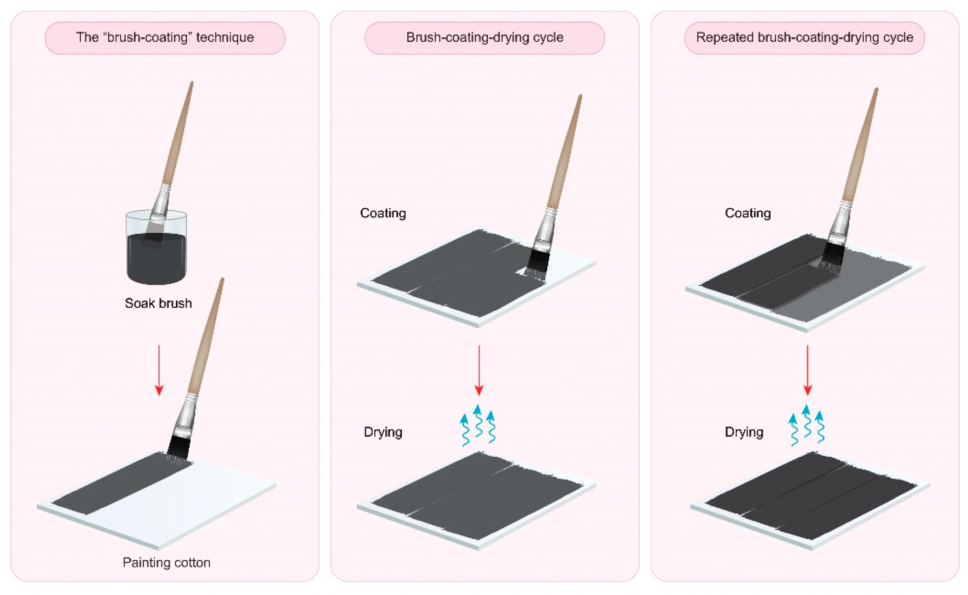
2.3. Preparation of Conductive Graphite Cotton Fabrics
3. Results and Discussion
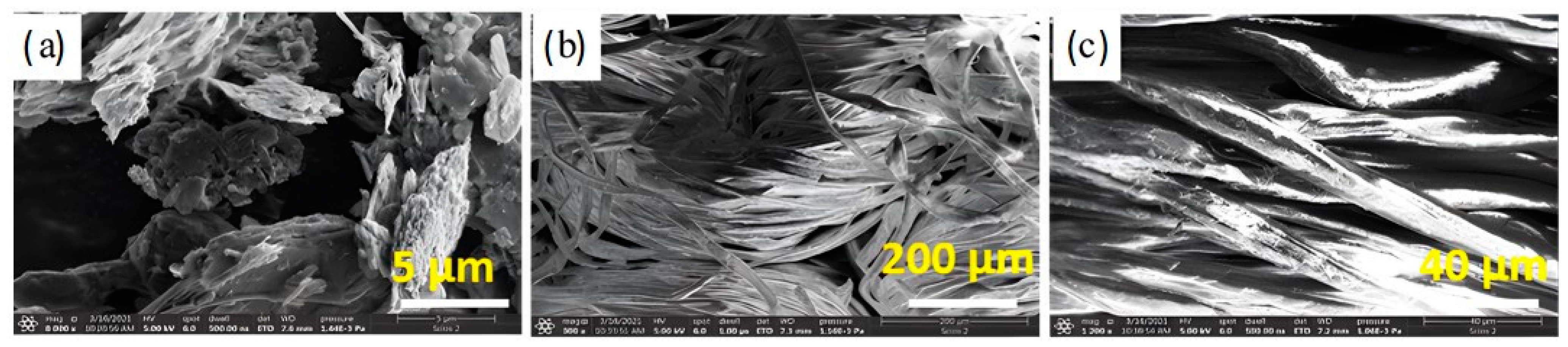
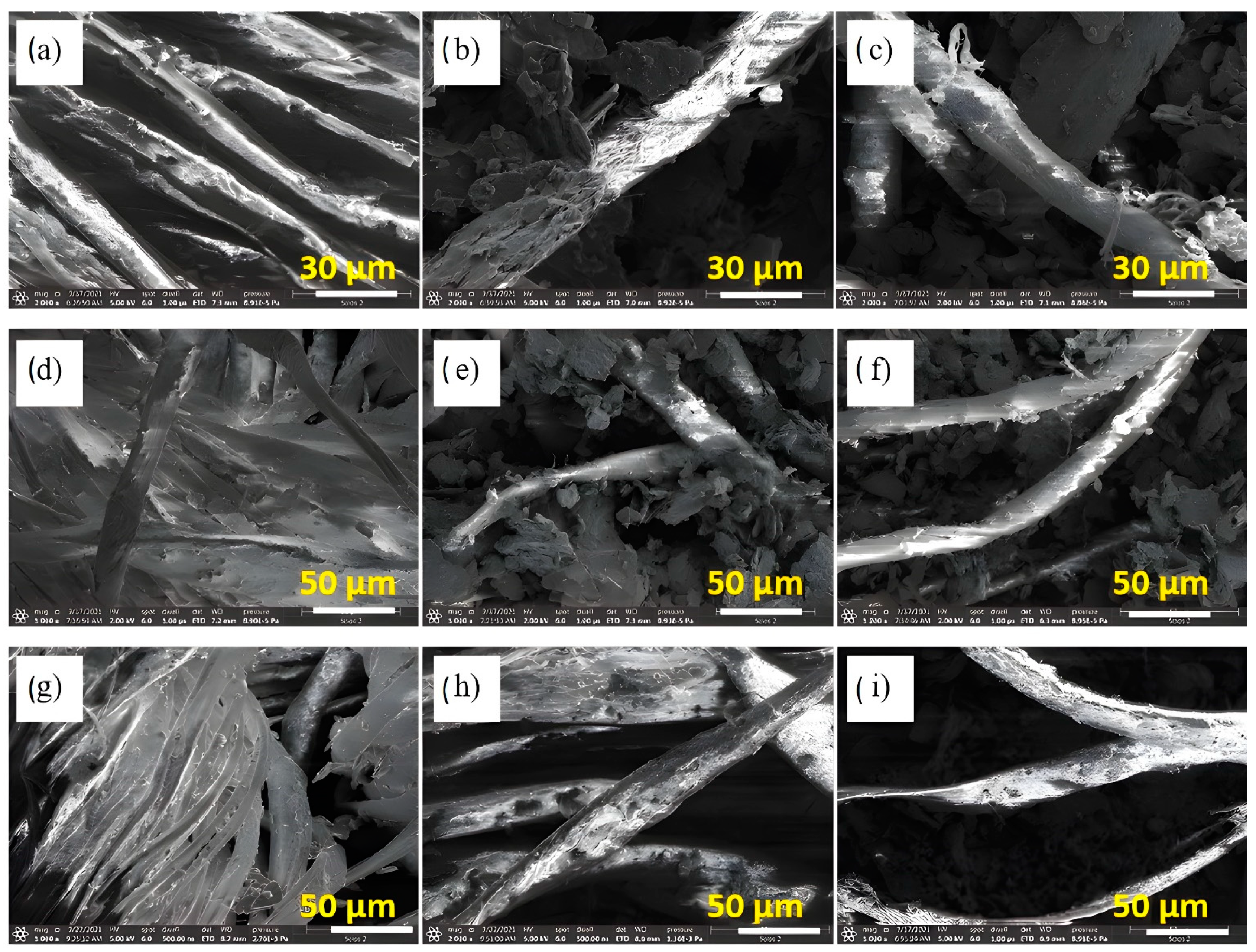
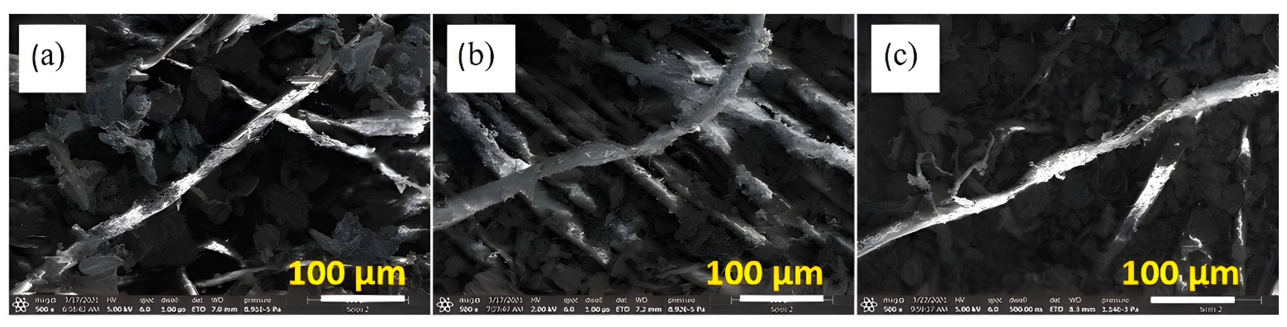
3.1. Morphological Observations
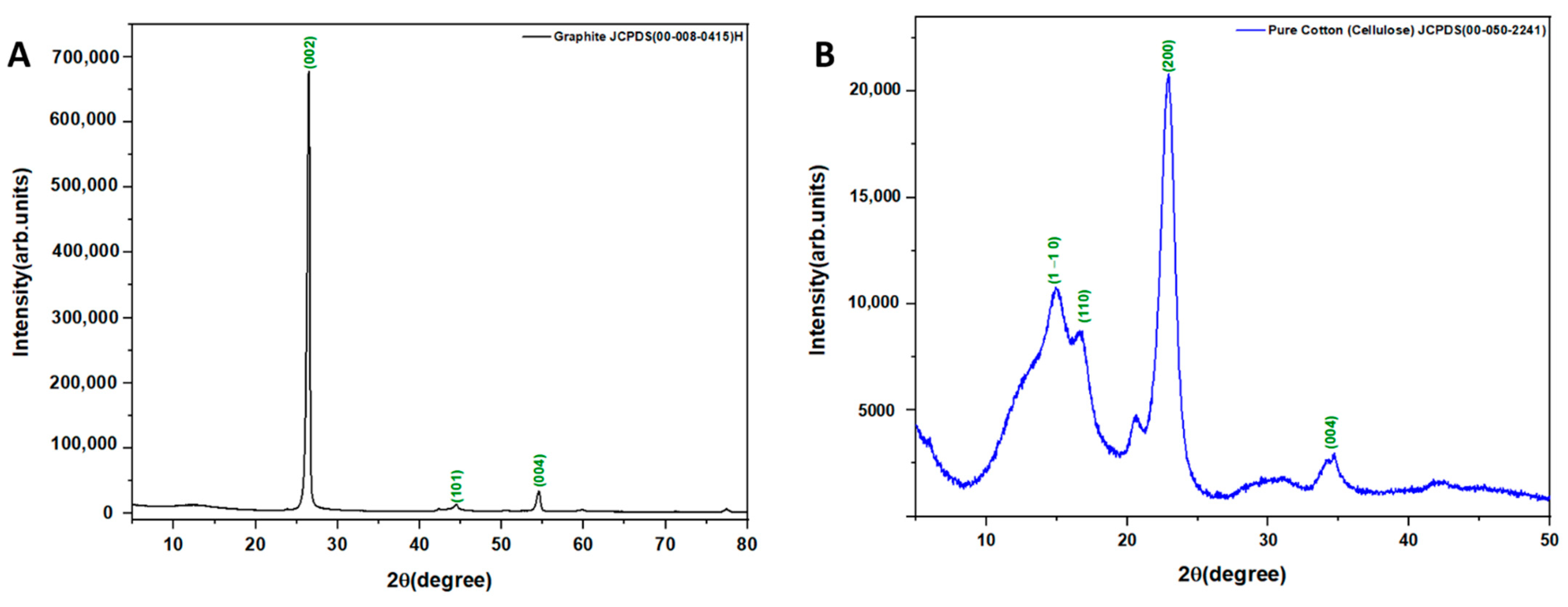
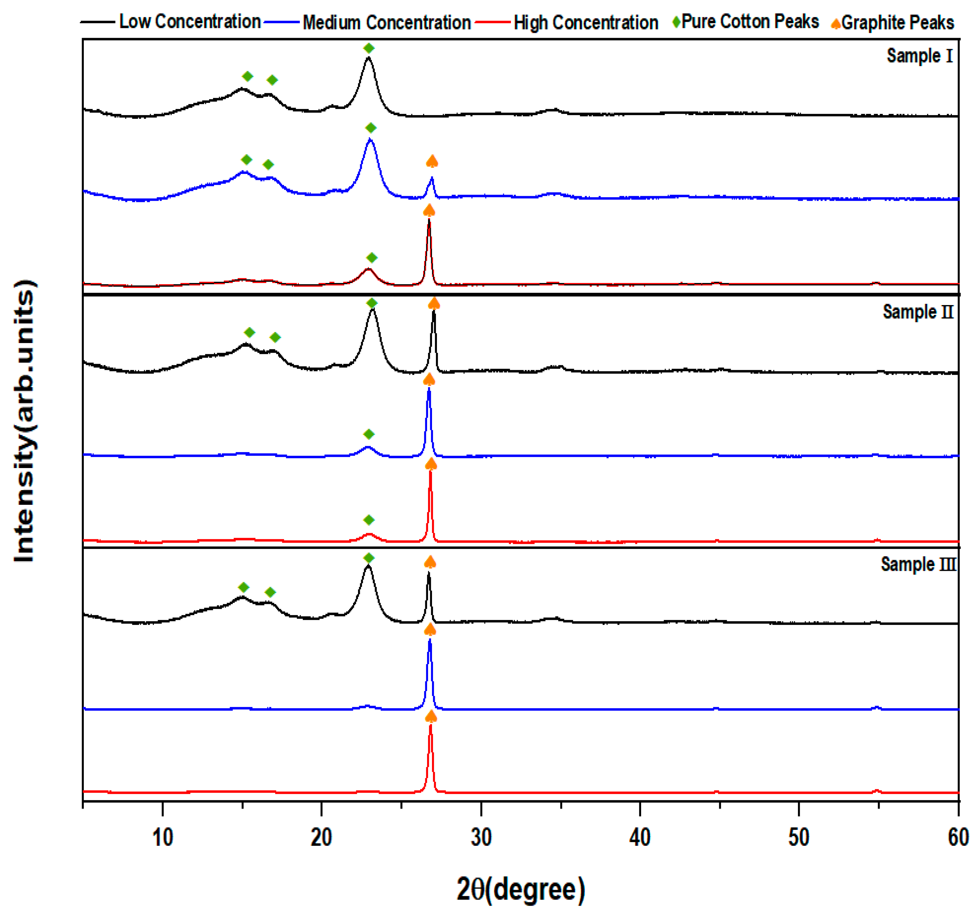
3.2. XRD Analysis
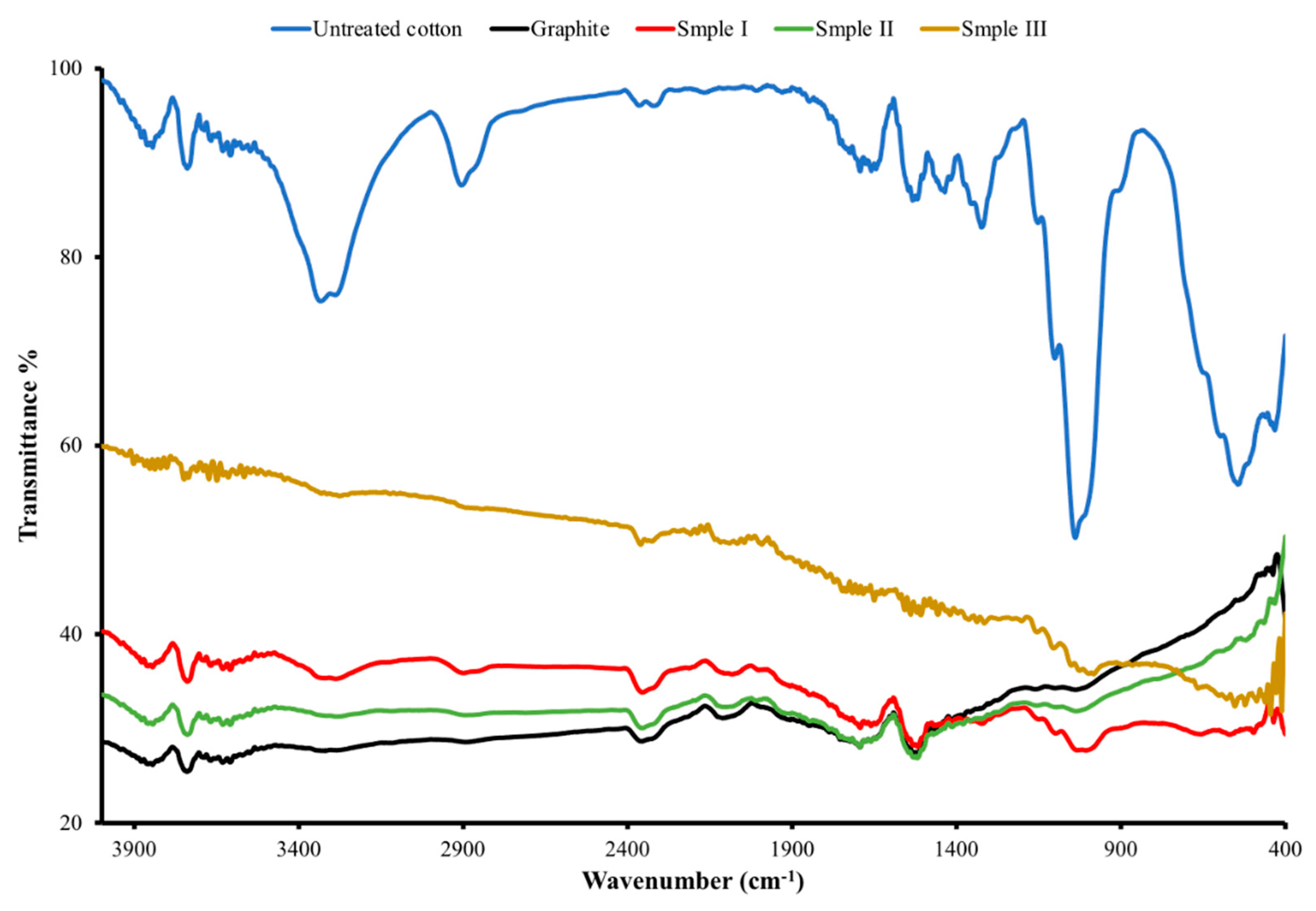
3.3. FTIR Analysis
3.4. Electrical Study
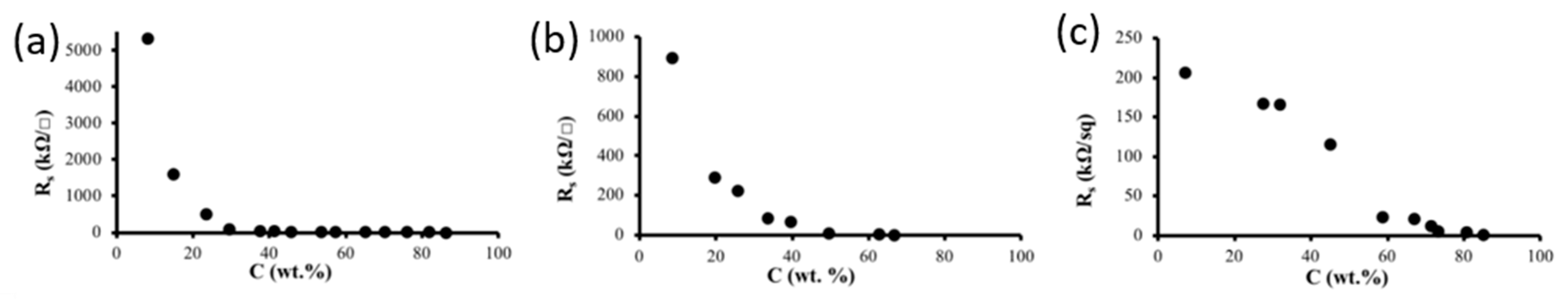
3.4.1. Sheet Resistance Measurements
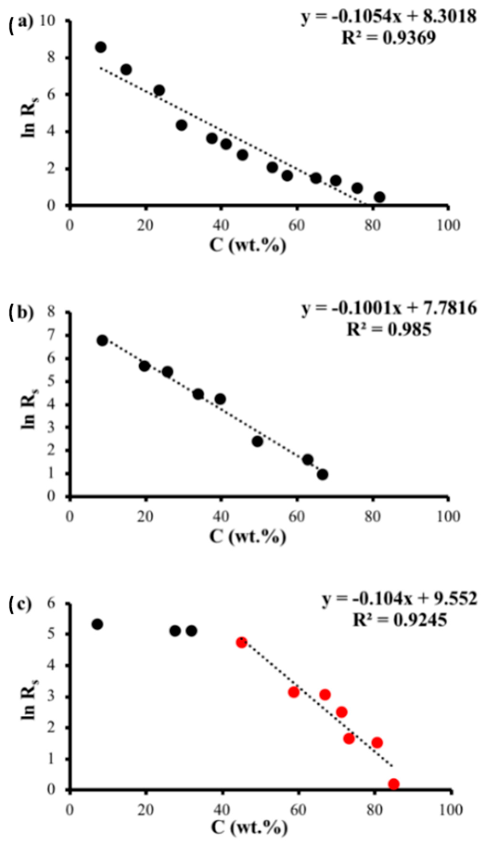
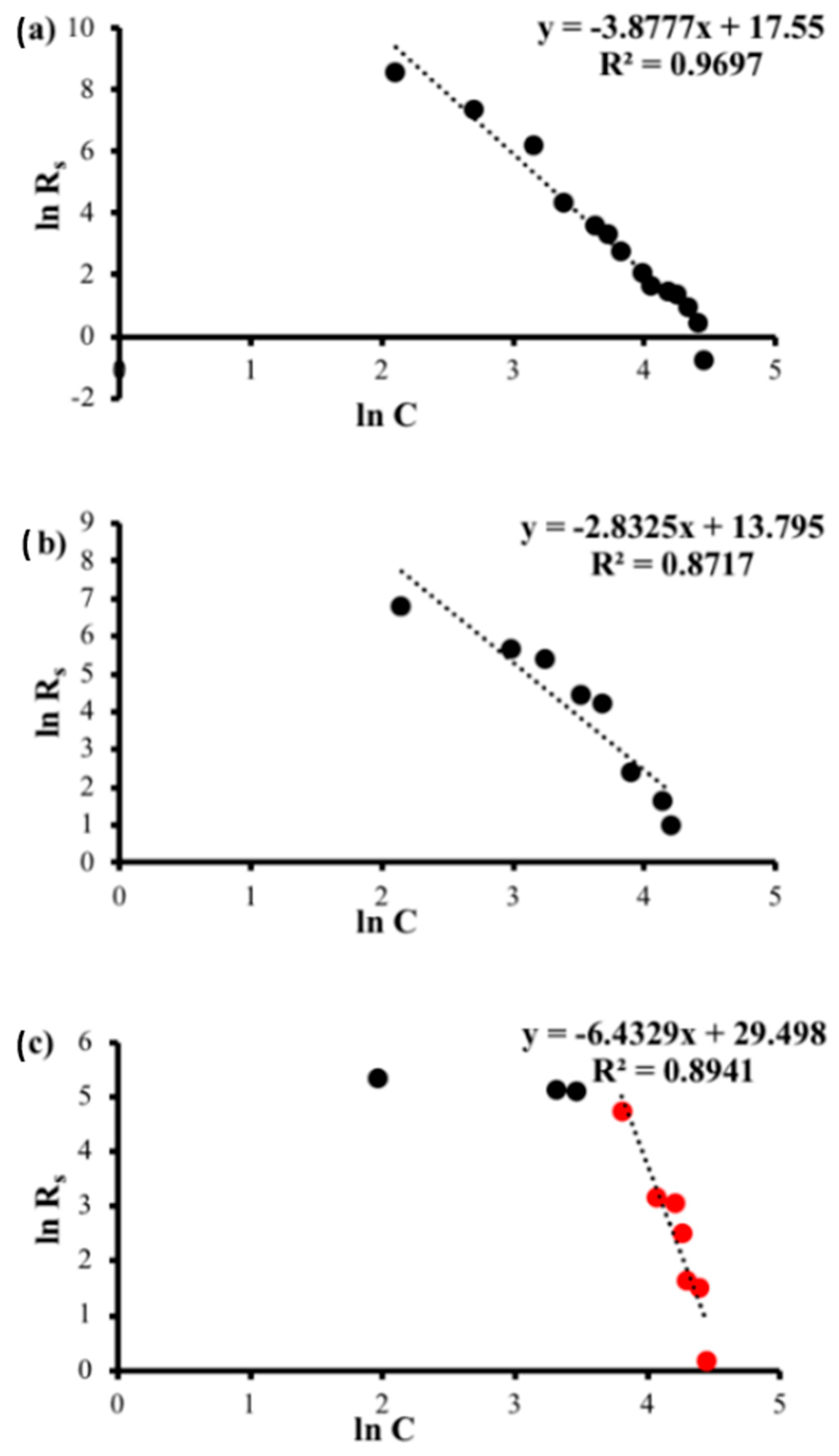
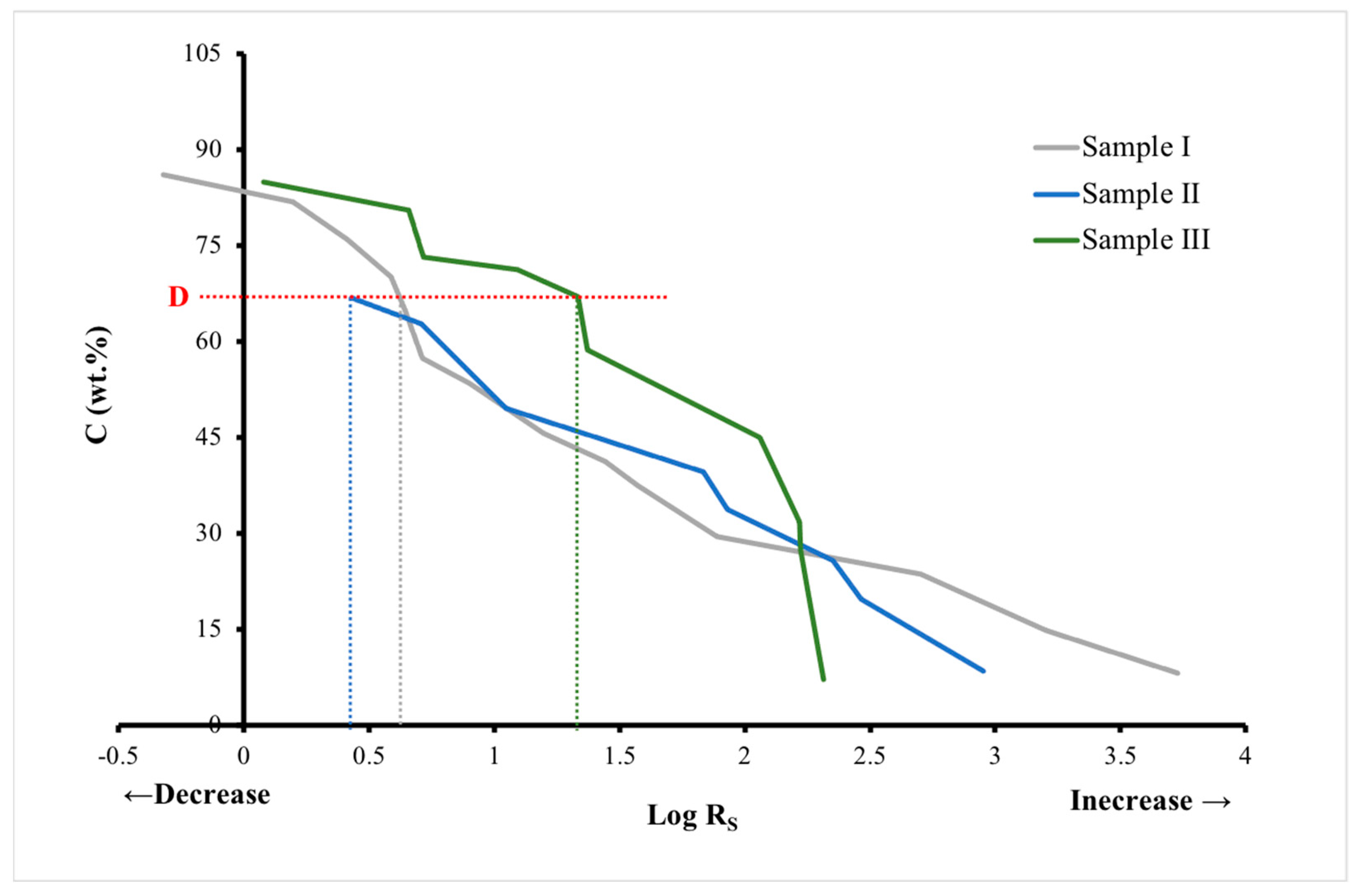
3.4.2. Sheet Resistance Theoretical Analysis
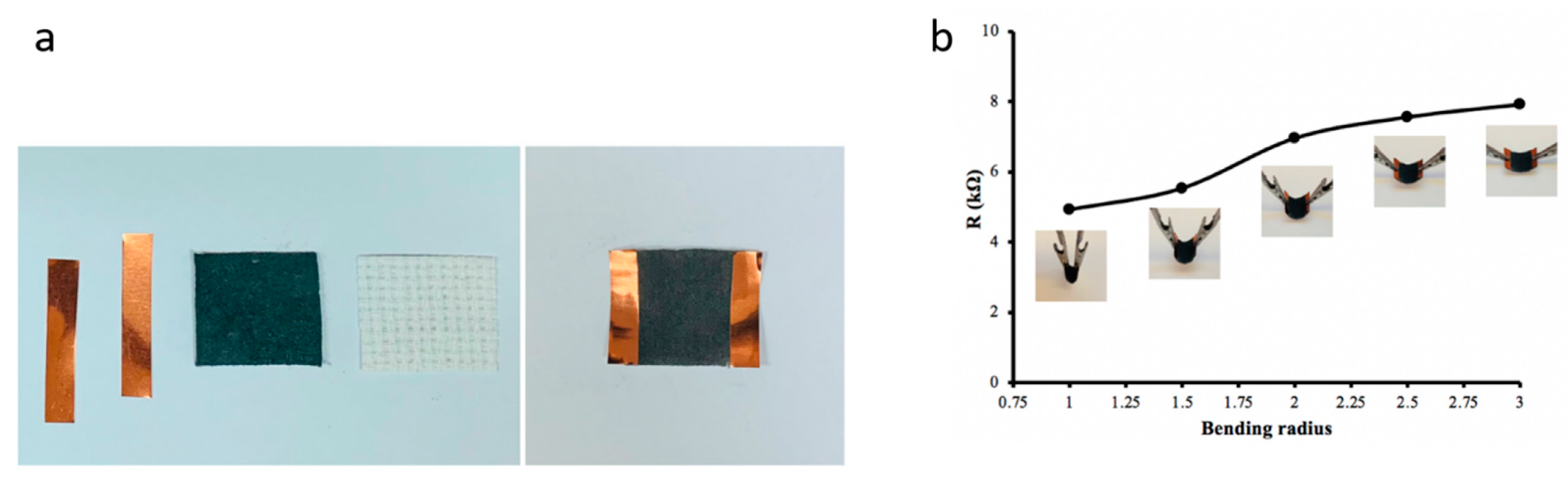
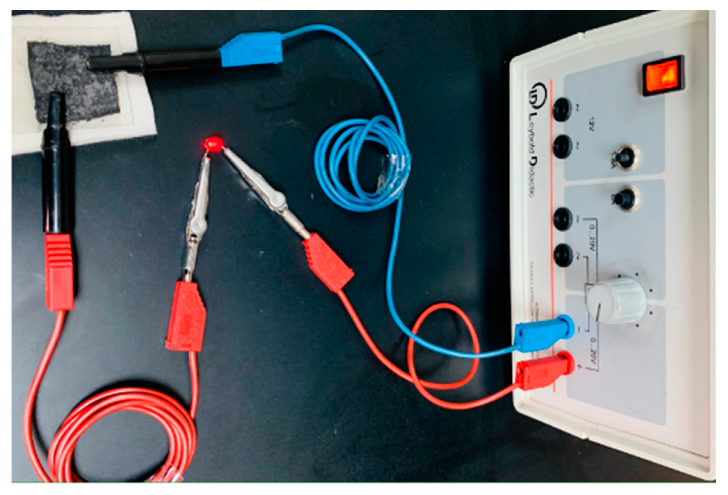
3.4.3. Graphite Cotton as an Electrical Conductor
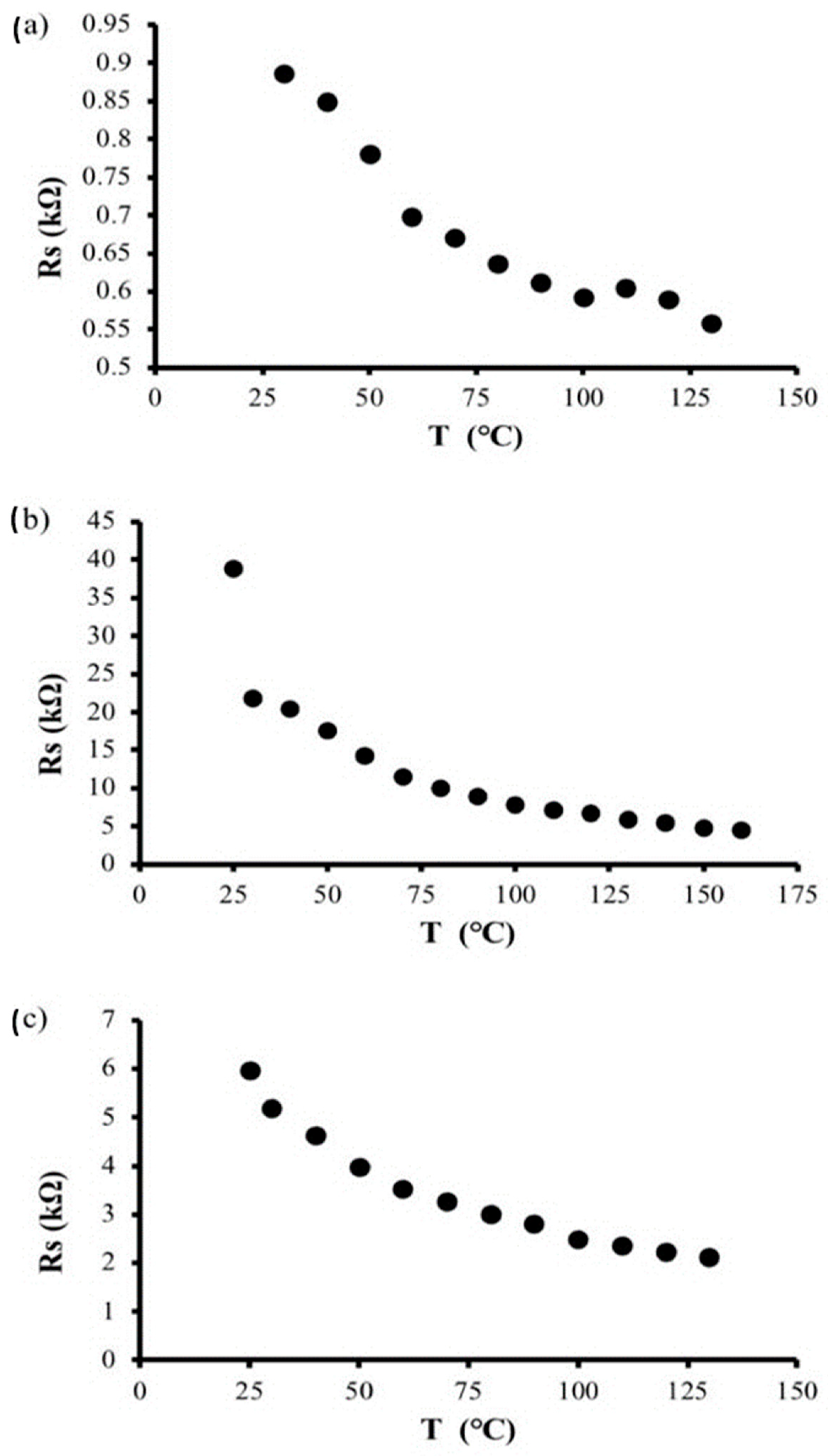
3.4.4. Temperature-Dependent Sheet Resistance
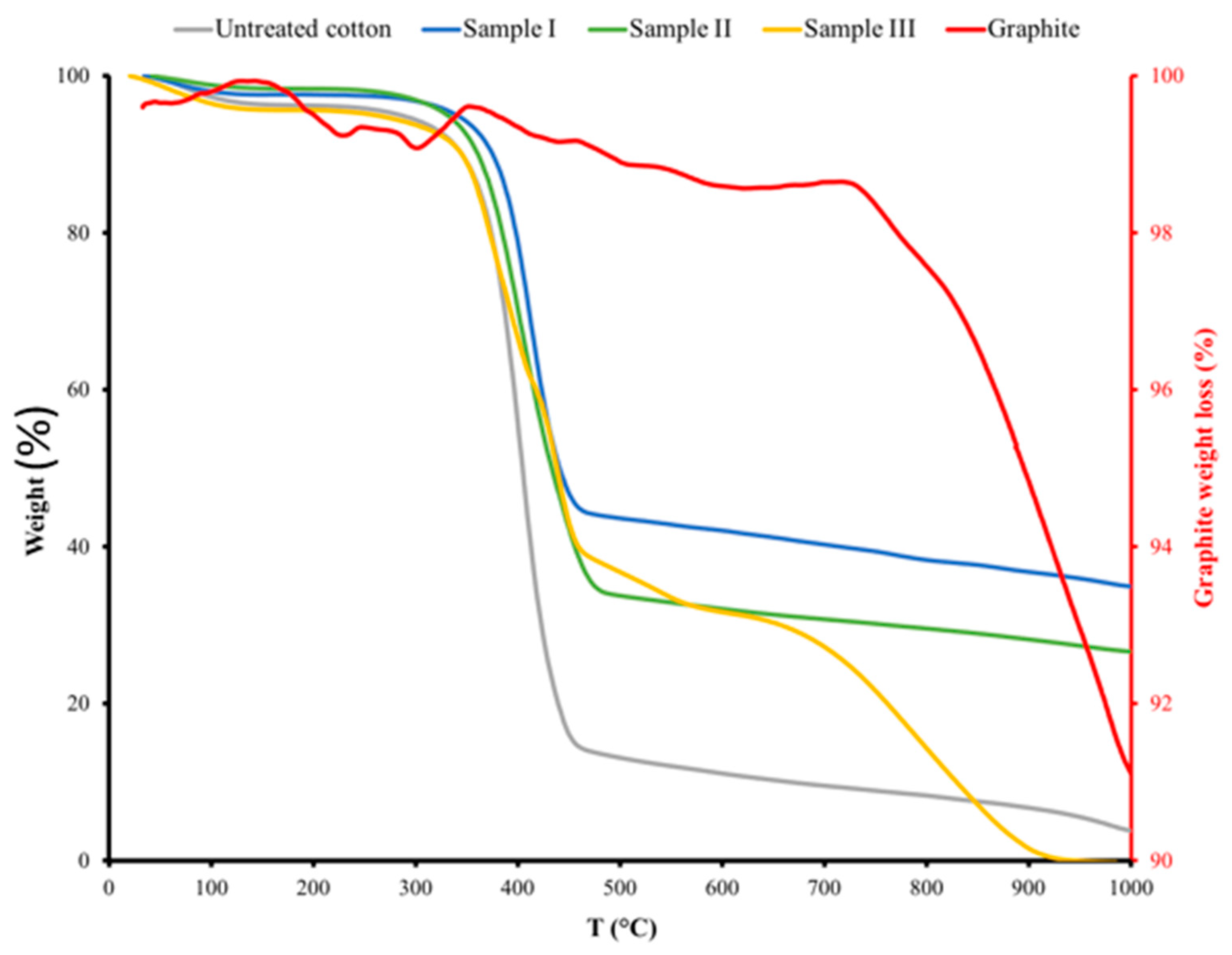
3.5. Thermal Analysis
3.6. Electrical Applications of Graphite Cotton Fabrics
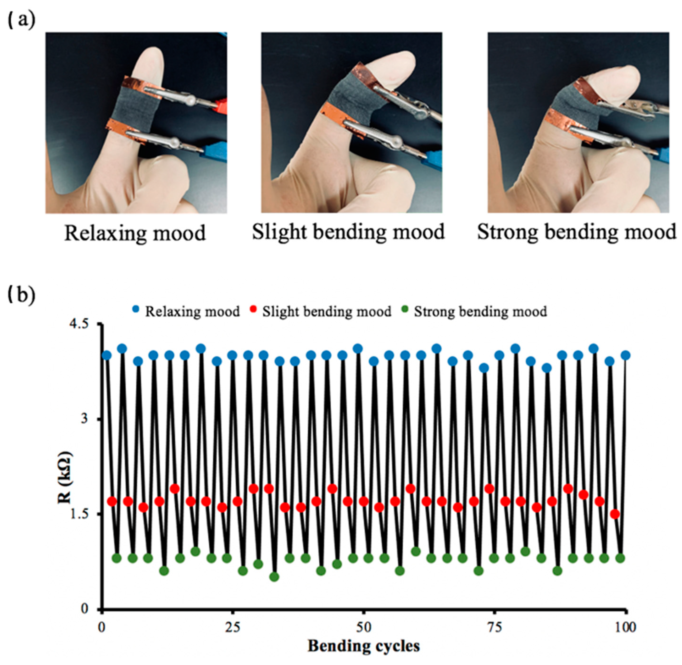
3.6.1. Wearable Flexible Strain Sensor
3.6.2. Conductive Interconnection
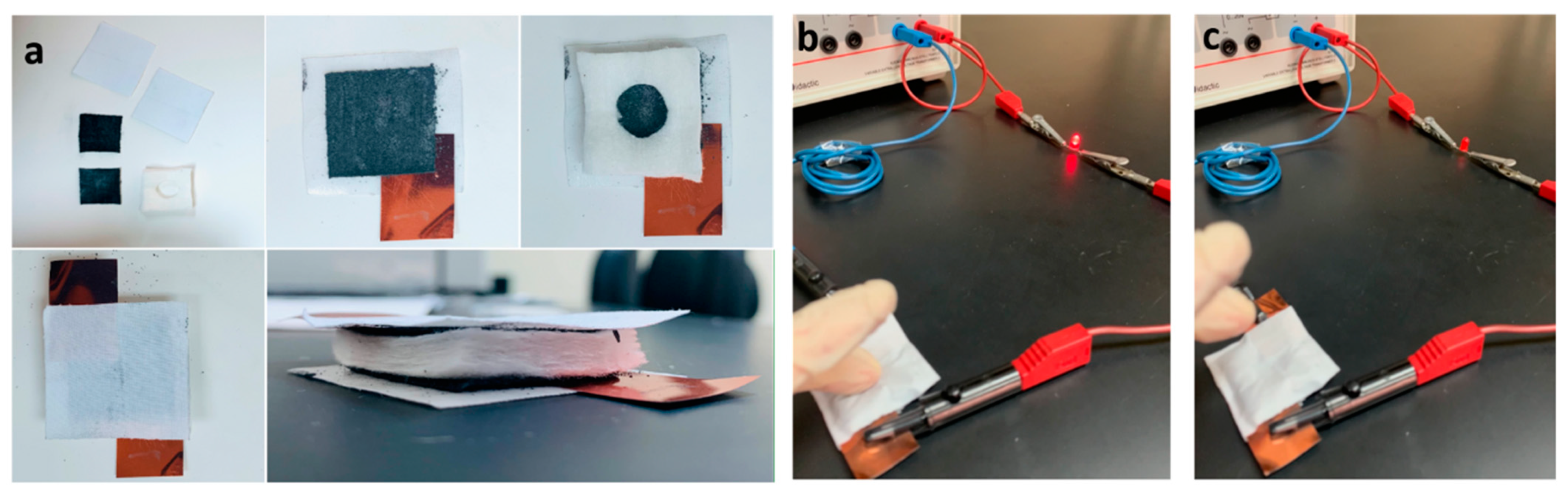
3.6.3. Electrical Cycle Switch
4. Conclusions
Author Contributions
Funding
Institutional Review Board Statement
Informed Consent Statement
Acknowledgments
Conflicts of Interest
References
- Chen, W.; Yang, S.; Wang, H.; Yang, K.; Wu, X.; Gao, F.; Zheng, B.; Qian, K.; Yao, W.; Zhang, T.; et al. Flexible, stretchable, waterproof (IPX7) electro-thermal films based on graphite nanoplatelets & polyurethane nanocomposites for wearable heaters. Chem. Eng. J. 2022, 431, 133990. [Google Scholar]
- Alamer, F.; Alnefaie, M.; Abdel Salam, M. Preparation and characterization of multi-walled carbon nanotubes-filled cotton fabrics. Results Phys. 2022, 33, 105205. [Google Scholar] [CrossRef]
- Walter, P.; Podsiadły, B.; Zych, M.; Kamiński, M.; Skalski, A.; Raczyński, T.; Janczak, D.; Jakubowska, M. CNT/Graphite/SBS conductive fibers for strain sensing in wearable telerehabilitation devices. Sensors 2022, 22, 800. [Google Scholar] [CrossRef]
- Shi, J.; Liu, S.; Zhang, L.; Yang, B.; Shu, L.; Yang, Y.; Ren, M.; Wang, Y.; Chen, J.; Chen, W.; et al. Smart textile-integrated microelectronic systems for wearable applications. Adv. Mater. 2020, 32, 1901958. [Google Scholar] [CrossRef]
- Zheng, X.; Shen, J.; Hu, Q.; Nie, W.; Wang, Z.; Zou, L.; Li, C. Vapor phase polymerized conducting polymer/MXene textiles for wearable electronics. Nanoscale 2021, 13, 1832–1841. [Google Scholar] [CrossRef]
- Niu, B.; Yang, S.; Hua, T.; Tian, X.; Koo, M. Facile fabrication of highly conductive, waterproof, and washable e-textiles for wearable applications. Nano Res. 2021, 14, 1043–1052. [Google Scholar] [CrossRef]
- Wang, X.; Li, Q.; Tao, X. Sensing mechanism of a carbon nanocomposite-printed fabric as a strain sensor. Compos. A Appl. Sci. Manuf. 2021, 144, 106350. [Google Scholar] [CrossRef]
- Wu, R.; Ma, L.; Patil, A.; Hou, C.; Zhu, S.; Fan, X.; Lin, H.; Yu, W.; Guo, W.; Lio, X.Y. All-textile electronic skin enabled by highly elastic spacer fabric and conductive fibers. ACS Appl. Mater. Interfaces 2019, 11, 33336–33346. [Google Scholar] [CrossRef]
- Sadi, M.S.; Kumpikaitė, E. Advances in the Robustness of Wearable Electronic Textiles: Strategies, Stability, Washability and Perspective. Nanomaterials 2022, 12, 2039. [Google Scholar] [CrossRef]
- Hou, S.; Zhu, T.; Shen, W.; Kang, F.; Inagaki, M.; Huang, Z.H. Exfoliated graphite blocks with resilience prepared by room temperature exfoliation and their application for oil-water separation. J. Hazard. Mater. 2022, 24, 127724. [Google Scholar] [CrossRef]
- Lan, C.; Guo, M.; Li, C.; Qiu, Y.; Ma, Y.; Sun, J. Axial alignment of carbon nanotubes on fibers to enable highly conductive fabrics for electromagnetic interference shielding. ACS Appl. Mater. Interfaces 2020, 12, 7477–7485. [Google Scholar] [CrossRef]
- Pullanchiyodan, A.; Manjakkal, L.; Dervin, S.; Shakthivel, D.; Dahiya, R. Metal coated conductive fabrics with graphite electrodes and biocompatible gel electrolyte for wearable supercapacitors. Adv. Mater. Technol. 2020, 5, 1901107. [Google Scholar] [CrossRef]
- Khair, N.; Islam, R.; Shahariar, H. Carbon-based electronic textiles: Materials, fabrication processes and applications. J. Mater. Sci. 2019, 54, 10079–10101. [Google Scholar] [CrossRef]
- Mengal, N.; Arbab, A.A.; Sahito, I.A.; Memon, A.A.; Sun, K.C.; Jeong, S.H. An electrocatalytic active lyocell fabric cathode based on cationically functionalized and charcoal decorated graphite composite for quasi-solid state dye sensitized solar cell. Sol. Energy 2017, 155, 110–120. [Google Scholar] [CrossRef]
- Liu, W.W.; Yan, X.B.; Lang, J.W.; Peng, C.; Xue, Q.J. Flexible and conductive nanocomposite electrode based on graphene sheets and cotton cloth for supercapacitor. J. Mater. Chem. 2012, 22, 17245–17253. [Google Scholar] [CrossRef]
- Hölscher, F.; Trümper, P.R.; Junger, I.J.; Hellkamp, E.S.; Ehrmann, A. Application methods for graphite as catalyzer in dye-sensitized solar cells. Optik 2019, 178, 1276–1279. [Google Scholar] [CrossRef]
- Sahito, I.A.; Sun, K.C.; Arbab, A.A.; Qadir, M.B.; Choi, Y.S.; Jeong, S.H. Flexible and conductive cotton fabric counter electrode coated with graphene nanosheets for high efficiency dye sensitized solar cell. J. Power Sources 2016, 319, 90–98. [Google Scholar] [CrossRef]
- Chen, K.H.; Goel, V.; Namkoong, M.J.; Wied, M.; Müller, S.; Wood, V.; Sakamoto, J.; Thornton, K.; Dasgupta, N.P. Enabling 6C fast charging of Li-Ion batteries with graphite/Hard carbon hybrid anodes. Adv. Energy Mater. 2021, 11, 2003336. [Google Scholar] [CrossRef]
- Sadi, M.S.; Yang, M.; Luo, L.; Cheng, D.; Cai, G.; Wang, X. Direct screen printing of single-faced conductive cotton fabrics for strain sensing, electrical heating and color changing. Cellulose 2019, 26, 6179–6188. [Google Scholar] [CrossRef]
- Veeramuthu, L.; Cho, C.-J.; Venkatesan, M.; Kumar, R.; Hsu, H.-Y.; Zhuo, B.-X.; Kau, L.-J.; Chung, M.-A.; Lee, W.-Y.; Kuo, C.-C. Muscle fibers inspired electrospun nanostructures reinforced conductive fibers for smart wearable optoelectronics and energy generators. Nano Energy 2022, 101, 107592. [Google Scholar] [CrossRef]
- Zhang, R.; Qu, M.; Wang, H.; Fan, M.; Chen, Q.; Tang, P.; Bin, Y. Moist-electric films based on asymmetric distribution of sodium alginate oxygen-containing functional groups. React. Funct. Polym. 2022, 181, 105421. [Google Scholar] [CrossRef]
- Bahadir, S.K.; Sahin, U.K. A wearable heating system with a controllable e-textile-based thermal panel. Wearable Technol. 2018, 175. [Google Scholar] [CrossRef] [Green Version]
- Lin, S.Y.; Zhang, T.Y.; Lu, Q.; Wang, D.Y.; Yang, Y.; Wu, X.M.; Ren, T.L. High-performance graphene-based flexible heater for wearable applications. RSC Adv. 2017, 7, 27001–27006. [Google Scholar] [CrossRef] [Green Version]
- Wang, J.; Lu, C.; Zhang, K. Textile-based strain sensor for human motion detection. Energy Environ. Mater. 2020, 3, 100. [Google Scholar] [CrossRef] [Green Version]
- Zahid, M.; Papadopoulou, E.L.; Athanassiou, A.; Bayer, I.S. Strain-responsive mercerized conductive cotton fabrics based on PEDOT: PSS/graphene. Mater. Des. 2017, 135, 213–222. [Google Scholar] [CrossRef]
- Yu, R.; Zhu, C.; Wan, J.; Li, Y.; Hong, X. Review of graphene-based textile strain sensors with emphasis on structure activity relationship. Polymers 2021, 13, 151. [Google Scholar] [CrossRef]
- De Oliveira, C.; Batistella, M.A.; de Souza, S.; de Souza, A. Development of flexible sensors using knit fabrics with conductive polyaniline coating and graphite electrodes. J. Appl. Polym. Sci. 2017, 134, 18. [Google Scholar] [CrossRef]
- Ren, J.; Wang, C.; Zhang, X.; Carey, T.; Chen, K.; Yin, Y.; Torrisi, F. Environmentally-friendly conductive cotton fabric as flexible strain sensor based on hot press reduced graphene oxide. Carbon 2017, 111, 622–630. [Google Scholar] [CrossRef] [Green Version]
- Li, P.; Zhao, L.; Jiang, Z.; Yu, M.; Li, Z.; Zhou, X.; Zhao, Y. A wearable and sensitive graphene-cotton based pressure sensor for human physiological signals monitoring. Sci. Rep. 2019, 9, 14457. [Google Scholar] [CrossRef] [Green Version]
- Tobjörk, D.; Österbacka, R. Paper electronics. Adv. Mater. 2011, 23, 1935–1961. [Google Scholar] [CrossRef]
- Alamer, F.A.; Badawi, N.M.; Alodhayb, A.; Okasha, R.M.; Kattan, N.A. Effect of dopant on the conductivity and stability of three different cotton fabrics impregnated with PEDOT: PSS. Cellulose 2020, 27, 531–543. [Google Scholar] [CrossRef]
- Alamer, F.A. A simple method for fabricating highly electrically conductive cotton fabric without metals or nanoparticles, using PEDOT: PSS. J. Alloys Compd. 2017, 702, 266–273. [Google Scholar] [CrossRef]
- Alamer, F.A.; Badawi, N.M.; Alsalmi, O. Preparation and characterization of conductive cotton fabric impregnated with single-walled carbon nanotubes. J. Electron. Mater. 2020, 49, 6582–6589. [Google Scholar] [CrossRef]
- Tadesse, M.G.; Mengistie, D.A.; Chen, Y.; Wang, L.; Loghin, C.; Nierstrasz, V. Electrically conductive highly elastic polyamide/lycra fabric treated with PEDOT:PSS and polyurethane. J. Mater. Sci. 2019, 54, 9591–9602. [Google Scholar] [CrossRef] [Green Version]
- Gaol, Q.; Wang, M.; Gao, C.; Ge, M. Light-colored conductive fabric coatings using uniform ATO@TiO2 whiskers. J. Mater. Sci. 2021, 56, 351–363. [Google Scholar]
- Li, T.T.; Wang, X.; Wang, Y.; Shiu, B.C.; Peng, H.K.; Lou, C.W.; Lin, J.H. Silver-coated conductive composite fabric with flexible, anti-flaming for electromagnetic interference shielding. J. Appl. Polym. Sci. 2022, 139, 51875. [Google Scholar] [CrossRef]
- Uzun, S.; Han, M.; Strobel, C.J.; Hantanasirisakul, K.; Goad, A.; Dion, G.; Gogotsi, Y. Highly conductive and scalable Ti3C2Tx-coated fabrics for efficient electromagnetic interference shielding. Carbon 2021, 174, 382–389. [Google Scholar] [CrossRef]
- Alamer, F.A. Structural and electrical properties of conductive cotton fabrics coated with the composite polyaniline/carbon black. Cellulose 2018, 25, 2075–2082. [Google Scholar] [CrossRef]
- Liu, K.; Yu, J.; Li, Y.; Yan, X.; Bai, D.; Liao, X.; Zhou, Z.; Gao, Y.; Yang, X.; Li, L. Carbon black from diesel soot for high-performance wearable pressure sensors. Adv. Mater. Technol. 2019, 4, 1900475. [Google Scholar] [CrossRef]
- Alamer, F.A.; Badawi, N.M. Fully Flexible, Highly Conductive Threads Based on single walled carbon nanotube (SWCNTs) and poly (3,4 ethylenedioxy thiophene) poly(styrenesulfonate) (PEDOT:PSS). Adv. Eng. Mater. 2021, 23, 2100448. [Google Scholar] [CrossRef]
- Alamer, F.A.; Badawi, N.M. Manufacturing organic environmentally friendly electrical circuits using the composites’ single-walled carbon nanotubes and PEDOT: PSS. Energy Technol. 2022, 10, 2100830. [Google Scholar] [CrossRef]
- Li, Q.; Zhu, Y.Q.; Eichhorn, S.J. Structural supercapacitors using a solid resin electrolyte with carbonized electrospun cellulose/carbon nanotube electrodes. J. Mater. Sci. 2018, 53, 14598–14607. [Google Scholar] [CrossRef]
- Sinha, S.K.; Alamer, F.A.; Woltornist, S.J.; Noh, Y.; Chen, F.; McDannald, A.; Allen, C.; Daniels, R.; Deshmukh, A.; Jain, M.; et al. Graphene and poly(3,4-ethylene dioxythiophene):poly(4-styrenesulfonate) on nonwoven fabric as a room temperature metal and its application as dry electrodes for electrocardiography. ACS Appl. Mater. Interfaces 2019, 11, 32339–32345. [Google Scholar] [CrossRef]
- Woltornist, S.J.; Alamer, F.A.; McDannald, A.; Jain, M.; Sotzing, G.A.; Adamson, D.H. Preparation of conductive graphene/graphite infused fabrics using an interface trapping method. Carbon 2015, 81, 38–42. [Google Scholar] [CrossRef]
- Liu, L.; Yu, Y.; Yan, C.; Li, K.; Zheng, Z. Wearable energy-dense and power-dense supercapacitor yarns enabled by scalable graphene–metallic textile composite electrodes. Nat. Commun. 2015, 6, 7260. [Google Scholar] [CrossRef] [Green Version]
- Qi, J.; Chen, Y.; Li, Q.; Sui, Y.; He, Y.; Meng, Q.; Wei, F.; Ren, Y.; Liu, J. Hierarchical NiCo layered double hydroxide on reduced graphene oxide-coated commercial conductive textile for flexible high-performance asymmetric supercapacitors. J. Power Sources 2020, 445, 227342. [Google Scholar] [CrossRef]
- Augustyn, P.; Rytlewski, P.; Moraczewski, K.; Mazurkiewicz, A. A review on the direct electroplating of polymeric materials. J. Mater. Sci. 2021, 56, 14881–14899. [Google Scholar] [CrossRef]
- Sadi, M.S.; Pan, J.; Xu, A.; Cheng, D.; Cai, G.; Wang, X. Direct dip-coating of carbon nanotubes onto polydopaminetemplated cotton fabrics for wearable applications. Cellulose 2019, 26, 7569–7579. [Google Scholar] [CrossRef]
- Ge, J.; Yao, H.; Hu, W.; Yu, X.; Yan, Y.; Mao, L.; Li, H.; Li, S.; Yu, S. Facile dip coating processed graphene/MnO2 nanostructured sponges as high performance supercapacitor electrodes. Nano Energy 2013, 2, 505–513. [Google Scholar] [CrossRef]
- Neves, A.I.S.; Rodrigues, D.P.; Alonso, E.T.; Pereira, M.S.; Amaral, V.S.; Melo, L.V.; Russo, S.; Schrijver, I.D.; Alves, H.; Craciun, M.F. Towards conductive textiles: Coating polymeric fibres with graphene. Sci. Rep. 2017, 7, 4250. [Google Scholar] [CrossRef] [Green Version]
- Saeed, M.; Alshammari, Y.; Majeed, S.A.; Al-Nasrallah, E. Chemical vapour deposition of graphene synthesis, characterization, and applications: A Review. Molecules 2020, 25, 3856. [Google Scholar] [CrossRef]
- Zeng, W.; Shu, L.; Li, Q.; Chen, S.; Wang, F.; Tao, X.M. Fiber-based wearable electronics: A review of materials, fabrication, devices, and applications. Adv. Mater. 2014, 26, 5310–5336. [Google Scholar] [CrossRef]
- Chatterjee, A.; Kumar, M.; Maity, S. Influence of graphene oxide concentration and dipping cycles on electrical conductivity of coated cotton textiles. J. Text. Inst. 2017, 108, 1910–1916. [Google Scholar] [CrossRef]
- Kim, H.; Lee, S.; Kim, H. Electrical heating performance of electro-conductive para-aramid knit manufactured by dip-coating in a graphene/waterborne polyurethane composite. Sci. Rep. 2019, 9, 1511. [Google Scholar] [CrossRef] [Green Version]
- Vahle, D.; Böttjer, R.; Heyden, K.; Ehrmann, A. Conductive polyacrylonitrile/graphite textile coatings. AIMS Mater. Sci. 2018, 5, 551–558. [Google Scholar] [CrossRef]
- Mizerska, U.; Fortuniak, W.; Makowski, T.; Svyntkivska, M.; Piorkowska, E.; Kowalczyk, D.; Brzezinski, S. Electrically conductive and hydrophobic rGO-containing organosilicon coating of cotton fabric. Prog. Org. Coat. 2019, 137, 105312. [Google Scholar] [CrossRef]
- Hiremath, R.K.; Rabinal, M.K.; Mulimani, B.G. Simple setup to measure electrical properties of polymeric films. Rev. Sci. Instrum. 2006, 77, 126106. [Google Scholar] [CrossRef]
- Haar, S.; Bruna, M.; Lian, J.X.; Tomarchio, F.; Olivier, Y.; Mazzaro, R.; Morandi, V.; Moran, J.; Ferrari, A.C.; Beljonne, D.; et al. Liquid-Phase Exfoliation of Graphite into Single- and Few-Layer Graphene with α-Functionalized Alkanes. J. Phys. Chem. Lett. 2016, 7, 2714–2721. [Google Scholar] [CrossRef] [Green Version]
- Hernandez, Y.; Nicolosi, V.; Lotya, M.; Blighe, F.M.; Sun, Z.; De, S.; McGovern, I.T.; Holland, B.; Byrne, M.; Gun’ko, Y.K.; et al. High-yield production of graphene by liquid-phase exfoliation of graphite. Nat. Nanotechnol. 2008, 3, 563–568. [Google Scholar] [CrossRef] [Green Version]
- You, X.; Feng, Q.; Yang, J.; Huang, K.; Hu, J. Shaoming DongPreparation of high concentration graphene dispersion with low boiling point solvents. J. Nanopart. Res. 2019, 21, 19. [Google Scholar] [CrossRef]
- Haar, S.; El Gemayel, M.; Shin, Y.; Melinte, G.; Squillaci, M.A.; Ersen, O.; Casiraghi, C.; Ciesielski, A.; Samorì, P. Enhancing the Liquid-Phase Exfoliation of Graphene in Organic Solvents upon Addition of n-Octylbenzene. Sci. Rep. 2015, 5, 16684. [Google Scholar] [CrossRef] [Green Version]
- Sayah, A.; Habelhames, F.; Bahloul, A.; Nessark, B.; Bonnassieux, Y.; Tendelier, D.; El Jouad, M. Electrochemical synthesis of polyaniline-exfoliated graphene composite films and their capacitance properties. J. Electroanal. Chem. 2018, 818, 26–34. [Google Scholar] [CrossRef]
- French, A. Idealized powder diffraction patterns for cellulose polymorphs. Cellulose 2014, 21, 885–896. [Google Scholar] [CrossRef]
- Dey, R.S.; Hajra, S.; Sahu, R.K.; Raj, C.R.; Panigrahi, M.K. A rapid room temperature chemical route for the synthesis of graphene: Metal-mediated reduction of graphene oxide. Chem. Commun. 2012, 48, 1787. [Google Scholar] [CrossRef]
- Nethravathi, C.; Rajamathi, M. Chemically modified graphene sheets produced by the solvothermal reduction of colloidal dispersions of graphite oxide. Carbon 2008, 46, 1994. [Google Scholar] [CrossRef]
- Kim, I.T.; Lee, J.; An, J.C.; Jung, E.; Lee, H.K.; Morita, M.; Shim, J. Capacity improvement of tin-deposited on carbon-coated graphite anode for rechargeable lithium ion batteries. Int. J. Electrochem. Sci. 2016, 11, 5807–5818. [Google Scholar] [CrossRef]
- Kongahge, D.; Foroughi, J.; Gambhir, S.; Spinks, G.M.; Wallace, G.G. Fabrication of graphene coated nonwoven textile for industrial applications. RSC Adv. 2016, 6, 73203–73209. [Google Scholar] [CrossRef] [Green Version]
- Karim, N.; Afroj, S.; Tan, S.; He, P.; Fernando, A.; Carr, C.; Novoselov, K.S. Scalable production of graphene-based wearable e-textiles. ACS Nano 2017, 11, 12266–12275. [Google Scholar] [CrossRef]


| Conductive Material Coated Fabric | Types of Substrate | Method | Electrical Connection | Strain Sensor (Bending Cycling) | Ref. |
|---|---|---|---|---|---|
| Graphite/graphene | PET fabric | interface trapping | 3.6 kΩ/□ | - | [44] |
| graphene oxide | fabric | Dipping-reduction | 0.19 MΩ/□ | - | [53] |
| graphene/waterborne/polyurethane | fabric | dip-coating | 1.5 kΩ/□ | - | [54] |
| polyacrylonitrile/graphite | fabric | doctor blade | 4 kΩ | - | [55] |
| graphene oxide | cotton | sol-gel | 6.70 MΩ/□ | - | [56] |
| graphene oxide | polyester nonwoven | simple dip coating | 330 Ω/□ | 50 | [57] |
| Reduced graphene oxide | cotton | simple pad-dry | 361.82 kΩ/□ | within 160 | [58] |
| PEDOT:PSS and graphene nanoflake | cotton | simple spray coating | ~25 Ω/□ | 1000 | [59] |
| graphite | Cotton | brush-coating-drying | 1.197 kΩ/□ | 100 | This study |
| Sample | JCPD Card File No | Miller Indices | Interplanar Spacing, d (nm) | |||
|---|---|---|---|---|---|---|
| h | k | l | ||||
| untreated Cotton | 00-050-2241 | 14.9879 | 1 | −1 | 0 | 5.9061 |
| 16.4866 | 1 | 1 | 0 | 5.3724 | ||
| 22.7814 | 2 | 0 | 0 | 3.9002 | ||
| Graphite | 00-008-0415 | 26.49 | 0 | 0 | 2 | 0.3370 |
| 44.48 | 1 | 0 | 1 | 0.2036 | ||
| 54.54 | 0 | 0 | 4 | 0.1682 | ||
| Low Concentration (Sample I) | 14.9879 | 1 | −1 | 0 | 5.9061 | |
| 16.4866 | 1 | 1 | 0 | 5.3724 | ||
| 22.7814 | 2 | 0 | 0 | 3.9002 | ||
| Medium Concentration (Sample I) | 14.9879 | 1 | −1 | 0 | 5.9061 | |
| 16.4866 | 1 | 1 | 0 | 5.3724 | ||
| 22.7814 | 2 | 0 | 0 | 3.9002 | ||
| 26.49 | 0 | 0 | 2 | 0.3370 | ||
| High Concentration (Sample I) | 22.7814 | 2 | 0 | 0 | 3.9002 | |
| 26.49 | 0 | 0 | 2 | 0.3370 | ||
| Low Concentration (Sample II) | 14.9879 | 1 | −1 | 0 | 5.9061 | |
| 16.4866 | 1 | 1 | 0 | 5.3724 | ||
| 22.7814 | 2 | 0 | 0 | 3.9002 | ||
| 26.49 | 0 | 0 | 2 | 0.3370 | ||
| Medium Concentration (Sample II) | 26.49 | 0 | 0 | 2 | 0.3370 | |
| High Concentration (Sample II) | 26.49 | 0 | 0 | 2 | 0.3370 | |
| Low Concentration (Sample III) | 14.9879 | 1 | −1 | 0 | 5.9061 | |
| 16.4866 | 1 | 1 | 0 | 5.3724 | ||
| 22.7814 | 2 | 0 | 0 | 3.9002 | ||
| 26.49 | 0 | 0 | 2 | 0.3370 | ||
| Medium Concentration (Sample III) | 26.49 | 0 | 0 | 2 | 0.3370 | |
| High Concentration (Sample III) | 26.49 | 0 | 0 | 2 | 0.3370 | |
| TGA Analysis | Untreated Cotton | Sample I | Sample II | Sample III | Graphite | |
|---|---|---|---|---|---|---|
| First Peak | Second Peak | |||||
| ∆Y (%) | 56.35 | 38.50 | 37.05 | 31.42 | 53.26 | 8.34 |
| Onset (°C) | 313.52 | 330.29 | 320.09 | 333.95 | 420.90 | 799.34 |
| Endset (°C) | 469.56 | 464.35 | 487.97 | 412.50 | 537.35 | 999.06 |
| To (°C) | 409.50 | 421.18 | 410.76 | 395.64 | 443.19 | 983.18 |
| Samples | Stability Range |
|---|---|
| Graphite powder | 100–800 °C |
| untreated cotton | 100–340 °C |
| Sample I | 100–350 °C |
| Sample II | 100–343 °C |
| Sample III | 100–340 °C |
Publisher’s Note: MDPI stays neutral with regard to jurisdictional claims in published maps and institutional affiliations. |
© 2022 by the authors. Licensee MDPI, Basel, Switzerland. This article is an open access article distributed under the terms and conditions of the Creative Commons Attribution (CC BY) license (https://creativecommons.org/licenses/by/4.0/).
Share and Cite
Alamer, F.A.; Aldeih, A.; Alsalmi, O.; Althagafy, K.; Al-Dossari, M. Construction of an Electrical Conductor, Strain Sensor, Electrical Connection and Cycle Switch Using Conductive Graphite Cotton Fabrics. Polymers 2022, 14, 4767. https://doi.org/10.3390/polym14214767
Alamer FA, Aldeih A, Alsalmi O, Althagafy K, Al-Dossari M. Construction of an Electrical Conductor, Strain Sensor, Electrical Connection and Cycle Switch Using Conductive Graphite Cotton Fabrics. Polymers. 2022; 14(21):4767. https://doi.org/10.3390/polym14214767
Chicago/Turabian StyleAlamer, Fahad Alhashmi, Asal Aldeih, Omar Alsalmi, Khalid Althagafy, and Mawaheb Al-Dossari. 2022. "Construction of an Electrical Conductor, Strain Sensor, Electrical Connection and Cycle Switch Using Conductive Graphite Cotton Fabrics" Polymers 14, no. 21: 4767. https://doi.org/10.3390/polym14214767