
Mechanical Properties, Surface Assessment, and Structural Analysis of Functionalized CFRPs after Accelerated Weathering

 , , ,
, , ,  , , and
Abstract
:
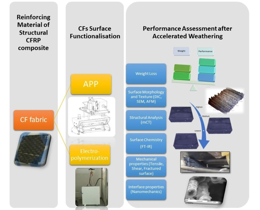
1. Introduction
2. Materials and Methods
2.1. Surface Treatments of CF Fabrics
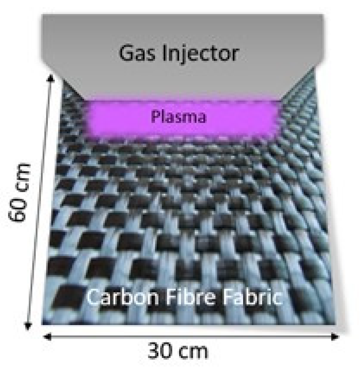
2.1.1. Air Pressure Plasma
2.1.2. Electropolymerisation of MAA
2.2. Composite Manufacturing
2.3. Weathering under Operational Conditions
2.4. Performance Assessment
3. Results
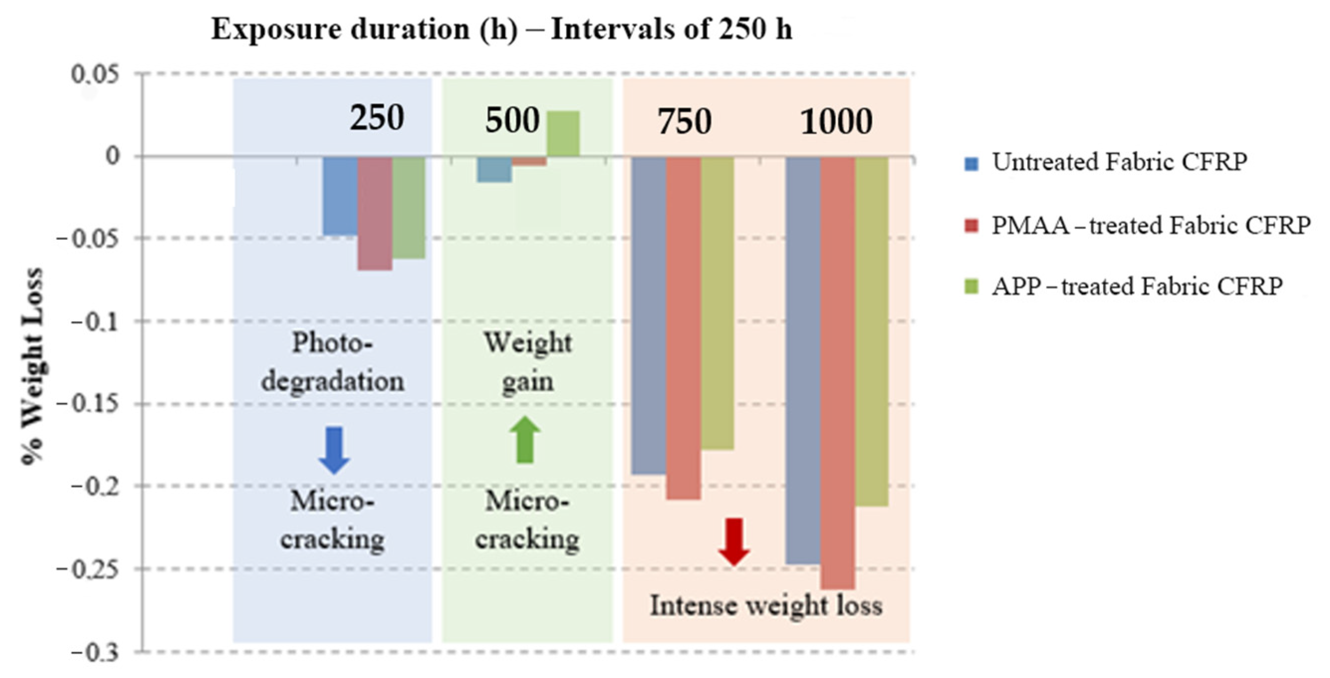
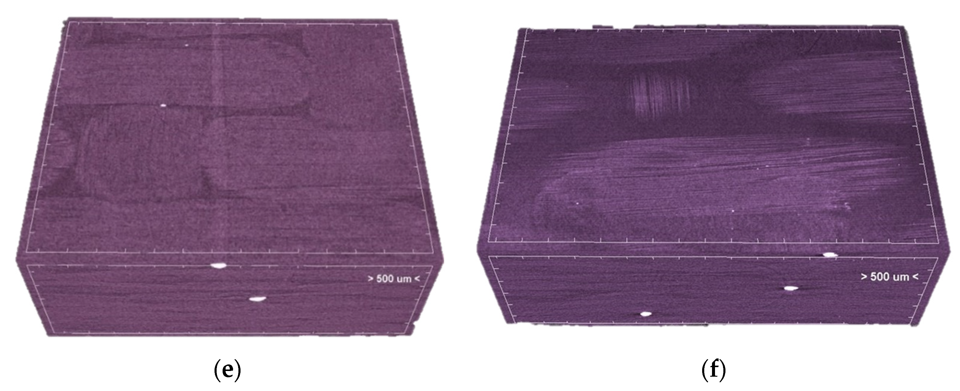
3.1. Deteriotation Mechanisms of Exposed CFRPs
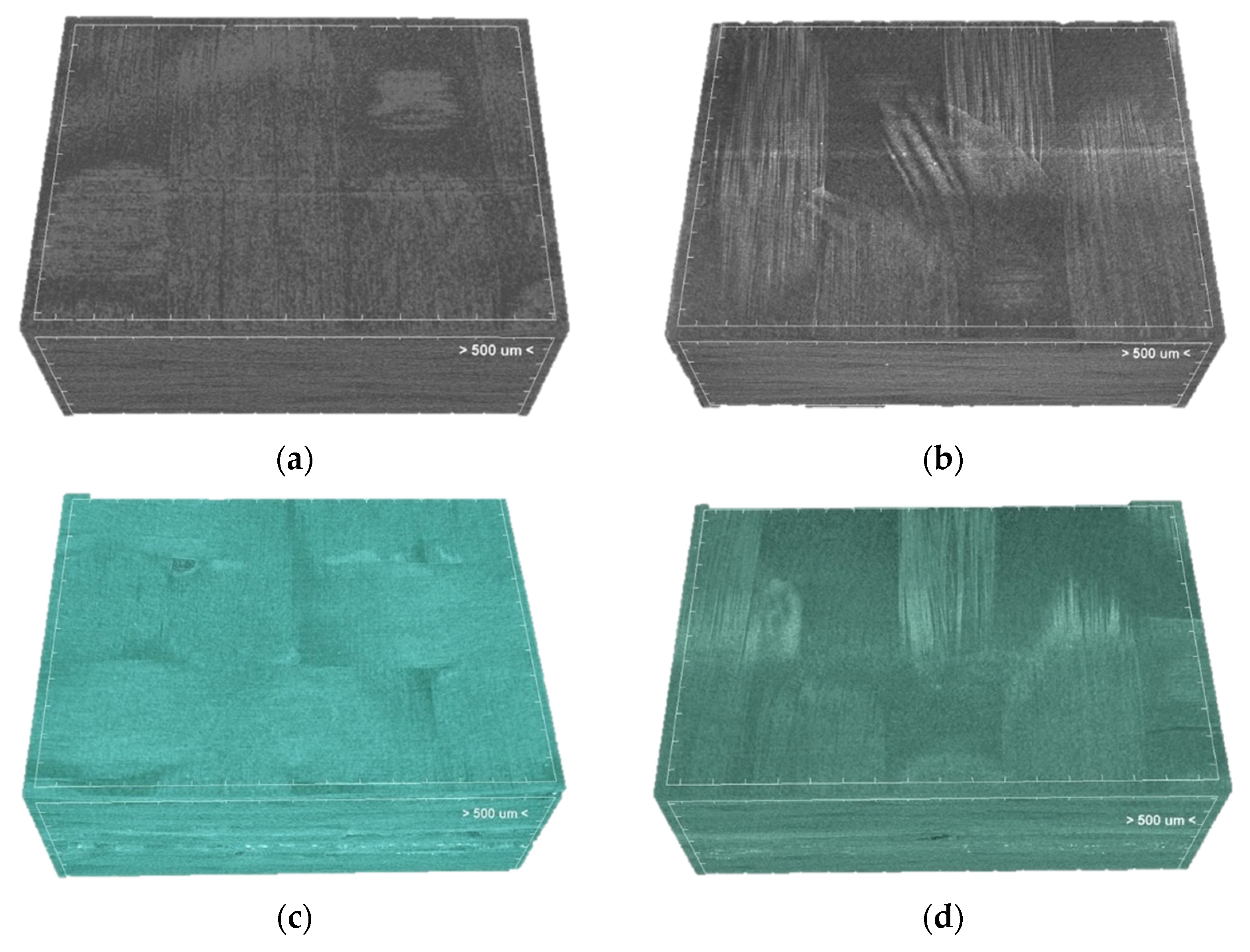
3.2. Structural Analysis
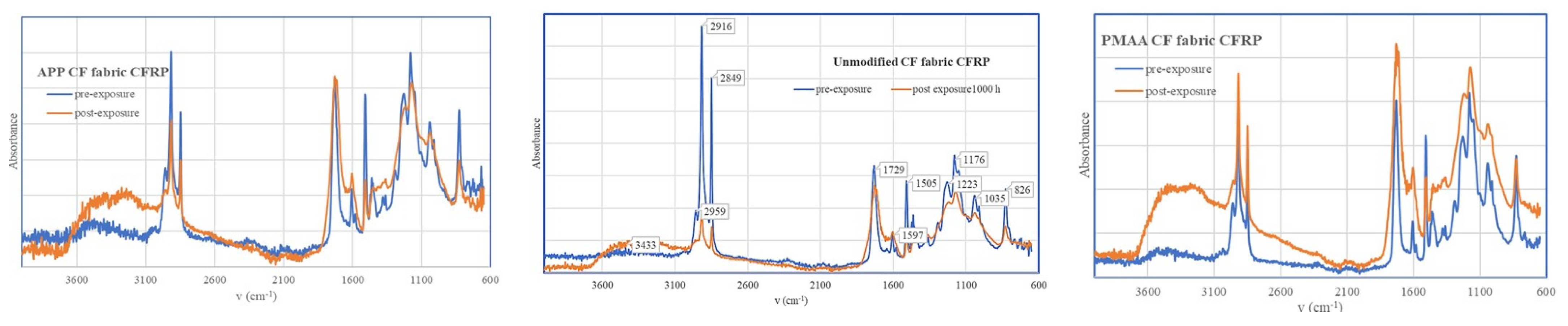
3.3. Surface Chemistry Examination
3.4. Mechanical Performance Assessment
3.4.1. Shear Testing
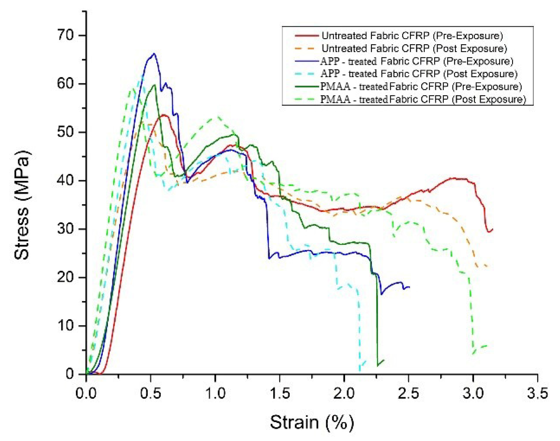
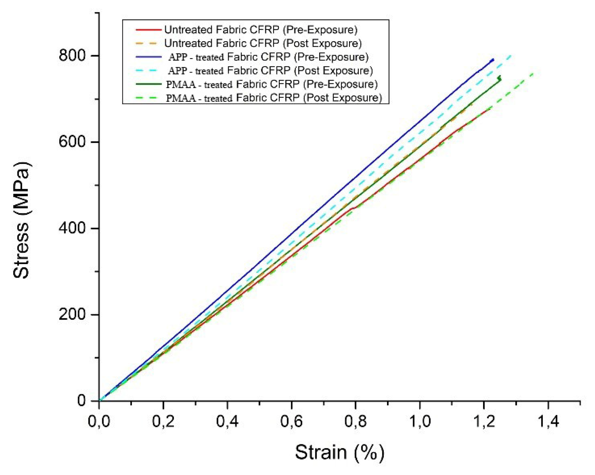
3.4.2. Tensile Testing
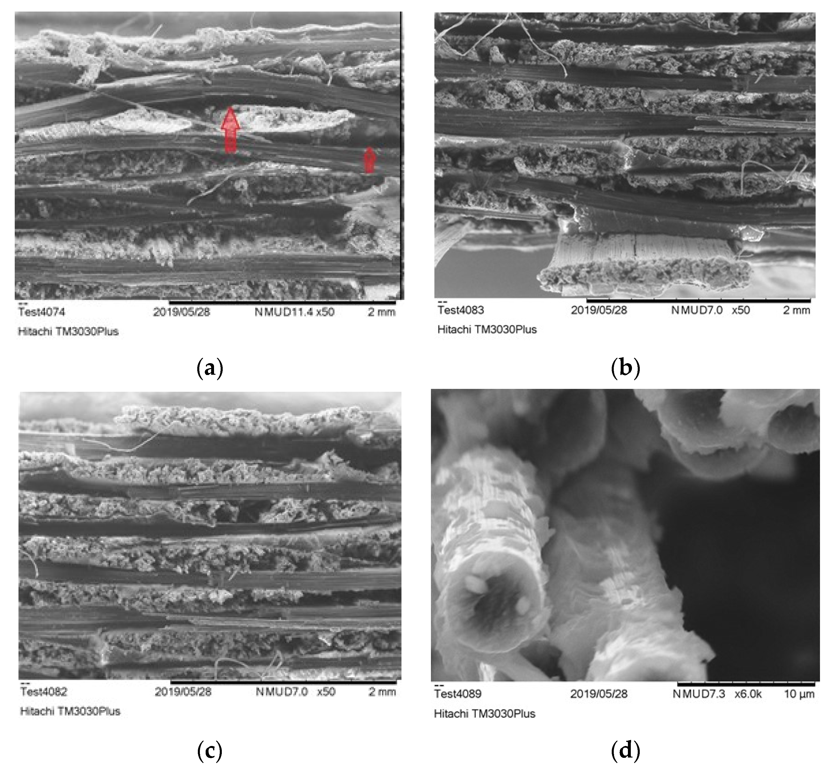
3.4.3. Study of Fractured Surface
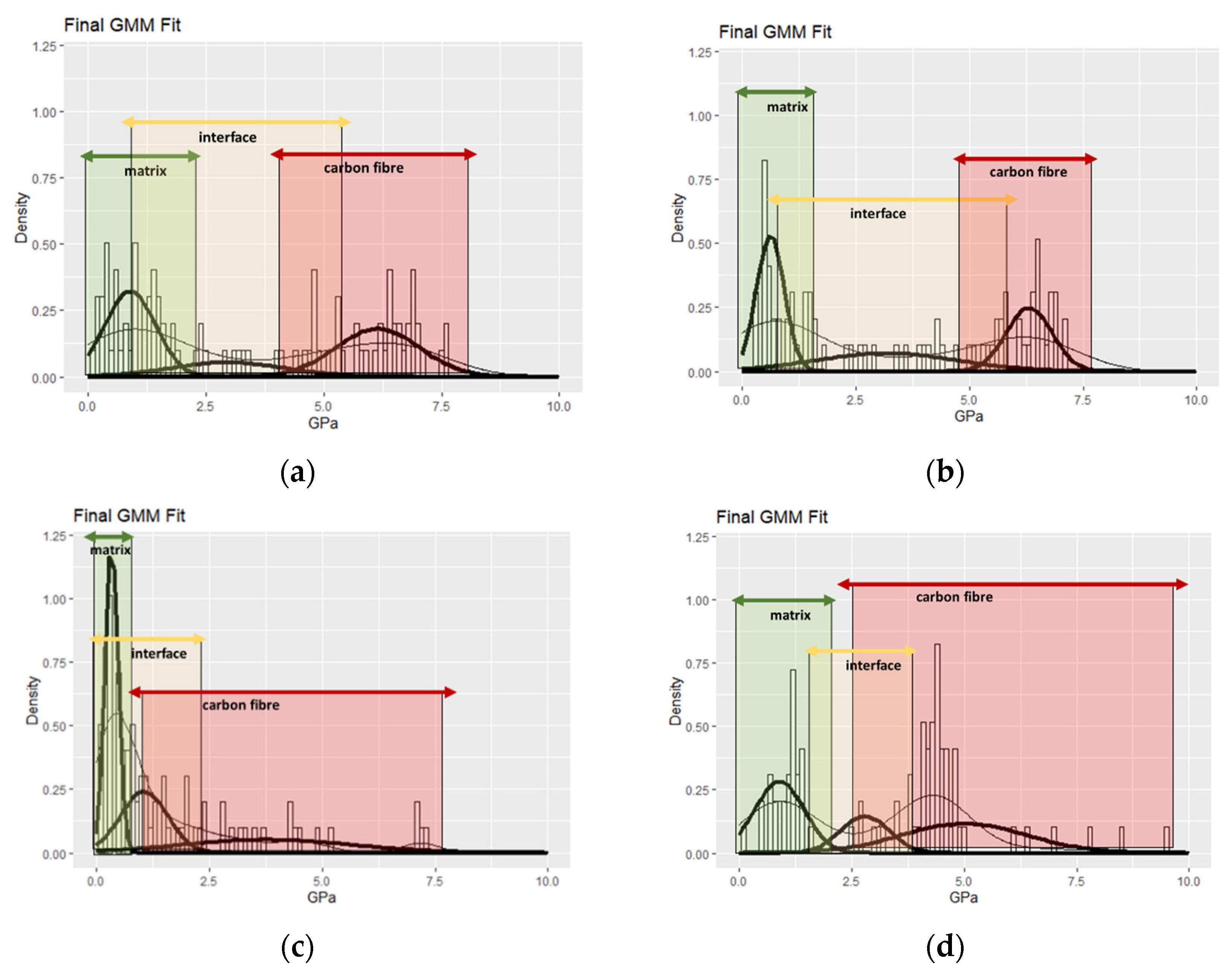
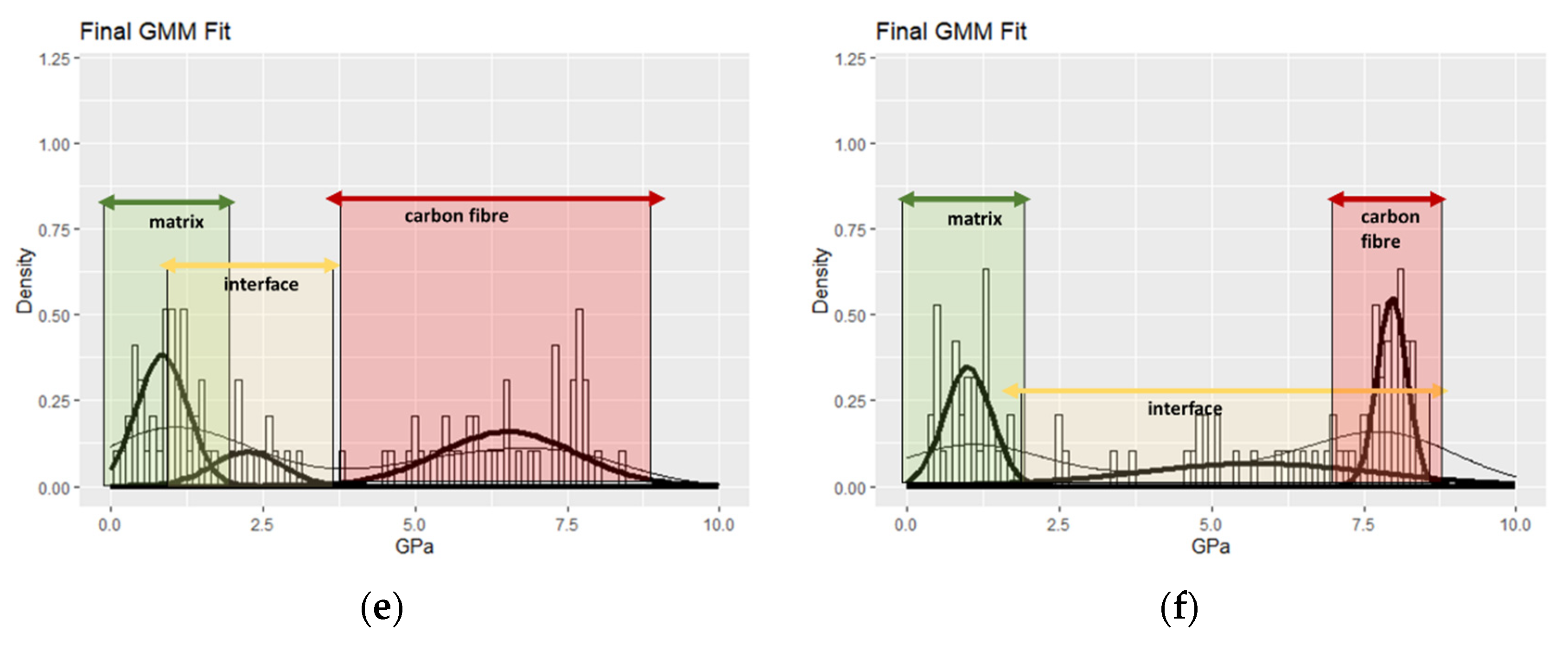
3.4.4. Mapping of Nanohardness
4. Conclusions
Supplementary Materials
Author Contributions
Funding
Institutional Review Board Statement
Informed Consent Statement
Data Availability Statement
Acknowledgments
Conflicts of Interest
References
- Koumoulos, E.P.; Trompeta, A.-F.; Santos, R.-M.; Martins, M.; Santos, C.M.; Iglesias, V.; Böhm, R.; Gong, G.; Chiminelli, A.; Verpoest, I.; et al. Research and Development in Carbon Fibres and Advanced High-Performance Composites Supply Chain in Europe: A Roadmap for Challenges and the Industrial Uptake. J. Compos. Sci. 2019, 3, 86. [Google Scholar] [CrossRef] [Green Version]
- Huang, X. Fabrication and Properties of Carbon Fibres. Materials 2009, 2, 2369–2403. [Google Scholar] [CrossRef]
- Frank, E.; Hermanutz, F.; Buchmeiser, M.R. Carbon Fibres: Precursors, Manufacturing, and Properties. Macromol. Mater. Eng. 2012, 297, 493–501. [Google Scholar] [CrossRef]
- Forintos, N.; Czigany, T. Multifunctional application of carbon fibre reinforced polymer composites: Electrical properties of the reinforcing carbon fibres—A short review. Compos. Part B Eng. 2019, 162, 331–343. [Google Scholar] [CrossRef]
- Meng, F.; McKechnie, J.; Pickering, S.J. An assessment of financial viability of recycled carbon fibre in automotive applications. Compos. Part A Appl. Sci. Manuf. 2018, 109, 207–220. [Google Scholar] [CrossRef] [Green Version]
- Improved carbon fibre structure for automotive. Reinf. Plast. 2018, 62, 4–5. [CrossRef]
- van de Werken, N.; Reese, M.S.; Taha, M.R.; Tehrani, M. Investigating the effects of fibre surface treatment and alignment on mechanical properties of recycled carbon fibre composites. Compos. Part A Appl. Sci. Manuf. 2019, 119, 38–47. [Google Scholar] [CrossRef]
- An, Q.; Rider, A.N.; Thostenson, E.T. Electrophoretic deposition of carbon nanotubes onto carbon-fibre fabric for production of carbon/epoxy composites with improved mechanical properties. Carbon 2012, 50, 4130–4143. [Google Scholar] [CrossRef]
- Yao, Z.; Wang, C.; Qin, J.; Su, S.; Wang, Y.; Wang, Q.; Yu, M.; Wei, H. Interfacial improvement of carbon fibre/epoxy composites using one-step method for grafting carbon nanotubes on the fibres at ultra-low temperatures. Carbon 2020, 164, 133–142. [Google Scholar] [CrossRef]
- Batista, N.L.; Iha, K.; Botelho, E.C. Evaluation of weather influence on mechanical and viscoelastic properties of polyetherimide/carbon fibre composites. J. Reinf. Plast. Compos. 2013, 32, 863–874. [Google Scholar] [CrossRef]
- Tsai, Y.I.; Bosze, E.J.; Barjasteh, E.; Nutt, S.R. Influence of hygrothermal environment on thermal and mechanical properties of carbon fibre/fibreglass hybrid composites. Compos. Sci. Technol. 2009, 69, 432–437. [Google Scholar] [CrossRef]
- Kumar, B.; Singh, R.; Nakamura, T. Degradation of Carbon Fibre-reinforced Epoxy Composites by Ultraviolet Radiation and Condensation. J. Compos. Mater. 2002, 36, 2713–2733. [Google Scholar] [CrossRef]
- Chevali, V.S.; Dean, D.R.; Janowski, G.M. Effect of environmental weathering on flexural creep behavior of long fibre-reinforced thermoplastic composites. Polym. Degrad. Stab. 2010, 95, 2628–2640. [Google Scholar] [CrossRef] [Green Version]
- Jelle, B.P.; Nilsen, T.-N. Comparison of accelerated climate ageing methods of polymer building materials by attenuated total reflectance Fourier transform infrared radiation spectroscopy. Constr. Build. Mater. 2011, 25, 2122–2132. [Google Scholar] [CrossRef] [Green Version]
- Xu, Y.; Li, H.; Yang, Y.; Hu, Y.; Tao, J. Determination of residual stresses in Ti/CFRP laminates after preparation using multiple methods. Compos. Struct. 2018, 210, 715–723. [Google Scholar] [CrossRef]
- Yamamoto, G.; Onodera, M.; Koizumi, K.; Watanabe, J.; Okuda, H.; Tanaka, F.; Okabe, T. Considering the stress concentration of fibre surfaces in the prediction of the tensile strength of unidirectional carbon fibre-reinforced plastic composites. Compos. Part A Appl. Sci. Manuf. 2019, 121, 499–509. [Google Scholar] [CrossRef]
- Lee, G.; Sung, M.; Youk, J.H.; Lee, J.; Yu, W.-R. Improved tensile strength of carbon nanotube-grafted carbon fibre reinforced composites. Compos. Struct. 2019, 220, 580–591. [Google Scholar] [CrossRef]
- Dilsiz, N. Plasma surface modification of carbon fibers: A review. J. Adhes. Sci. Technol. 2000, 14, 975–987. [Google Scholar] [CrossRef]
- Klan, A.; Dragatogiannis, D.; Jagdale, P.; Rovere, M.; Rosso, C.; Tagliaferro, A.; Charitidis, C. Novel carbon fibers synthesis, plasma functionalization, and application to polymer composites. Express Polym. Lett. 2021, 15, 361–372. [Google Scholar]
- Tiwari, S.; Bijwe, J. Surface Treatment of Carbon Fibres—A Review. Procedia Technol. 2014, 14, 505–512. [Google Scholar] [CrossRef] [Green Version]
- Semitekolos, D.; Kainourgios, P.; Jones, C.; Rana, A.; Koumoulos, E.P.; Charitidis, C.A. Advanced carbon fibre composites via poly methacrylic acid surface treatment; surface analysis and mechanical properties investigation. Compos. Part B Eng. 2018, 155, 237–243. [Google Scholar] [CrossRef]
- Cho, B.-G.; Hwang, S.-H.; Park, M.; Park, J.K.; Park, Y.-B.; Chae, H.G. The effects of plasma surface treatment on the mechanical properties of polycarbonate/carbon nanotube/carbon fibre composites. Comp. Part B Eng. 2019, 160, 436–445. [Google Scholar] [CrossRef]
- Chengcheng, S.; Junying, M.; Jianping, L.; Hailang, W. Effect of Atmospheric Pressure Plasma Treatment on Adhesive Bonding of Carbon Fiber Reinforced Polymer. Polymers 2019, 11, 139. [Google Scholar]
- Jianping, L.; Chengcheng, S.; Junying, M.; Hailang, W.; Shuang, W. Effect of atmospheric pressure plasma treatment on surface physicochemical properties of carbon fiber reinforced polymer and its interfacial bonding strength with adhesive. Comp Part B Eng. 2020, 199, 108237. [Google Scholar]
- Tendero, C.; Tixier, C.; Tristant, P.; Desmaison, J.; Leprince, P. Atmospheric pressure plasmas: A review. Spectrochim. Acta Part B At. Spectrosc. 2006, 61, 2–30. [Google Scholar] [CrossRef]
- Giorcelli, M.; Guastella, S.; Mandracci, P.; Liang, Y.; Li, X.; Tagliaferro, A. Carbon fibre functionalization by plasma treatment for adhesion enhancement on polymers. AIP Conf. Proc. 2018, 1981, 020142. [Google Scholar] [CrossRef]
- Li, Z.; Wang, J.; Tong, Y.; Xu, L. Anodic Oxidation on Structural Evolution and Tensile Properties of Polyacrylonitrile Based Carbon Fibres with Different Surface Morphology. J. Mater. Sci. Technol. 2012, 28, 1123–1129. [Google Scholar] [CrossRef]
- ASTM D3171-15. Standard Test Methods for Constituent Content of Composite Materials; ASTM International: West Conshohocken, PA, USA, 2015. [Google Scholar]
- ASTM G154-16. Standard Practice for Operating Fluorescent Ultraviolet (UV) Lamp Apparatus for Exposure of Nonmetallic Materials; ASTM International: West Conshohocken, PA, USA, 2016. [Google Scholar]
- Garcea, S.; Wang, Y.; Withers, P. X-ray computed tomography of polymer composites. Compos. Sci. Technol. 2018, 156, 305–319. [Google Scholar] [CrossRef]
- ASTM D2344/D2344M-16. Standard Test Method for Short-Beam Strength of Polymer Matrix Composite Materials and Their Laminate; ASTM International: West Conshohocken, PA, USA, 2016. [Google Scholar]
- ASTM D638-14. Standard Test Method for Tensile Properties of Plastics; ASTM International: West Conshohocken, PA, USA, 2014. [Google Scholar]
- Konstantopoulos, G.; Koumoulos, E.P.; Charitidis, C.A. Classification of mechanism of reinforcement in the fibre-matrix interface: Application of Machine Learning on nanoindentation data. Mater. Design. 2020, 192, 108705. [Google Scholar] [CrossRef]
- González, M.G.; Cabanelas, J.C.; Baselga, J. Applications of FTIR on Epoxy Resins—Identification, Monitoring the Curing Process, Phase Separation and Water Uptake. 2012. Available online: https://www.intechopen.com/chapters/36178 (accessed on 4 November 2021).
- Mülhaupt, R. New Resins and Nanosystems for High-Performance Adhesives. Adhesion 2005, 189–203. [Google Scholar] [CrossRef]
- Goda, K.; Miwa, Y.; Kodama, H. Effect of IFSS on tensile strength of unidirectional fibre composites using 3D-FEM simulation. Adv. Compos. Mater. 2003, 12, 73–89. [Google Scholar] [CrossRef]
- Sammaknejad, N.; Zhao, Y.; Huang, B. A review of the Expectation Maximization algorithm in data-driven process identification. J. Process. Control. 2018, 73, 123–136. [Google Scholar] [CrossRef]
- Huang, Y.; Meng, X.; Xie, Y.; Lv, Z.; Wan, L.; Cao, J.; Feng, J. Friction spot welding of carbon fibre-reinforced polyetherimide laminate. Compos. Struct. 2018, 189, 627–634. [Google Scholar] [CrossRef]
- Díez-Pascual, A.M.; Gómez-Fatou, M.A.; Ania, F.; Flores, A. Nanoindentation Assessment of the Interphase in Carbon Nanotube-Based Hierarchical Composites. J. Phys. Chem. C 2012, 116, 24193–24200. [Google Scholar] [CrossRef]
- Sun, Y.; Zhao, G.; Yang, F. Anisotropic Behavior of the Nanoindentation of Single Carbon Fibres. Nanosci. Nanotechnol. Lett. 2014, 6, 596–600. [Google Scholar] [CrossRef]
- Csanádi, T.; Németh, D.; Zhang, C.; Dusza, J. Nanoindentation derived elastic constants of carbon fibres and their nanostructural based predictions. Carbon 2017, 119, 314–325. [Google Scholar] [CrossRef] [Green Version]
- García-Moreno, I.; Caminero, M.; Rodríguez, G.P.; López-Cela, J.J. Effect of Thermal Ageing on the Impact Damage Resistance and Tolerance of Carbon-Fibre-Reinforced Epoxy Laminates. Polymers 2019, 11, 160. [Google Scholar] [CrossRef] [Green Version]
- Kim, J.; Mauchauffé, R.; Kim, D.; Kim, J.; Moon, S.Y. Mechanism study of atmospheric-pressure plasma treatment of carbon fibre reinforced polymers for adhesion improvement. Surf. Coat. Technol. 2020, 393, 125841. [Google Scholar] [CrossRef]
- Wang, Z.; Xian, G.; Zhao, X.-L. Effects of hydrothermal aging on carbon fibre/epoxy composites with different interfacial bonding strength. Constr. Build. Mater. 2018, 161, 634–648. [Google Scholar] [CrossRef]
- Sun, J.; Zhao, F.; Yao, Y.; Jin, Z.; Liu, X.; Huang, Y. High efficient and continuous surface modification of carbon fibres with improved tensile strength and interfacial adhesion. Appl. Surf. Sci. 2017, 412, 424–435. [Google Scholar] [CrossRef]
- Hardiman, M.; Vaughan, T.; McCarthy, C. Fibrous composite matrix characterisation using nanoindentation: The effect of fibre constraint and the evolution from bulk to in-situ matrix properties. Compos. Part A Appl. Sci. Manuf. 2014, 68, 296–303. [Google Scholar] [CrossRef]


| Plasma Power | Carriage Speed | Total Number of Passages (for Each Side) | Distance Electrodes—Sample | Carrier Gas (In Proximity of Plasma) |
|---|---|---|---|---|
| 500 W | 5.4 m/s | 30 | 2.05 mm | Argon |
| Electrochemical Treatment | Electropolymerisation | |||||||
|---|---|---|---|---|---|---|---|---|
| Aqueous Solution | Potential (V) | Number of Cycles | Scan Rate (V/s) | Monomer Concentration (M) | Potential (V) | Electrolyte Concentration (M) | Crosslinker Concentration (mM) | Electro-polymerisation time (s) |
| 5% H2SO4 | −3 to +3 | 10 | 0.1 | 0.3 | −0.435 | 0.4 | 10 | 3600 |
| Specimen Type | Matrix | Matrix Weight Mixing Ratio | Reinforcement | Fibre Volume Fraction (%) |
|---|---|---|---|---|
| Untreated Fabric CFRP | Araldite LY 556 + Aradur 917 + Accelerator DY 070 | 100:90:0.5 | G0926 | 56.3% |
| APP-treated Fabric CFRP | APP-treated G0926 | 56.8% | ||
| PMAA-treated Fabric CFRP | PMAA-treated G0926 | 56.6% |
| Phase | Range (h) | Phenomenon | Observation | Weight Loss Reduction Rate (h−1) | ||
|---|---|---|---|---|---|---|
| Ref | PMAA | APP | ||||
| 1 | 0–250 | Photo degradation that leads to micro-cracking | Initial decrease in weight | −0.00019 | −0.00028 | −0.00025 |
| 2 | 250–500 | Micro-cracking that permits increase in moisture ingress [10] | Weight gain | +0.00013 | +0.00025 | +0.00036 |
| 3 | >500 | Removal of material from the surface of the specimens [12] (Confirmed also by DIC and WLI, Section 3.1, Table 5). | Intense weight loss compared to phase 1 | −0.00071 | −0.00081 | −0.00082 |
| −0.00022 | −0.00022 | −0.00014 | ||||
| Sample | DIC | SEM | WLI | ||
|---|---|---|---|---|---|
| Pre-Exposure | Post Exposure | Post Exposure | Pre-Exposure | Post Exposure | |
| Unmodified fabric CFRP |  |  |  | ||
| APP fabric CFRP | |||||
| PMAA CFRP | |||||
| Pre-Exposure | Post Exposure | |||||||
|---|---|---|---|---|---|---|---|---|
| Specimen Type | Degree of Anisotropy | Open Porosity | Closed Porosity | Total Porosity | Degree of Anisotropy | Open Porosity | Closed Porosity | Total Porosity |
| Untreated Fabric CFRP | 3.28 | 0.0019 | 0.0234 | 0.0253 | 4.31 | 0.0203 | 0.0256 | 0.0459 |
| APP-treated Fabric CFRP | 3.91 | 0.001 | 0.0122 | 0.0132 | 4.33 | 0.0115 | 0.0129 | 0.0244 |
| PMAA-treated Fabric CFRP | 3.38 | 0.0021 | 0.0185 | 0.0206 | 3.56 | 0.0156 | 0.0195 | 0.0351 |
| Band (cm−1) | Assignment |
|---|---|
| 3100–3600 | O–H stretching |
| ~3000 | Stretching of C–H of the oxirane ring |
| 2919, 2850 | Stretching C–H of CH2 and CH |
| 1730 | Ester group |
| 1368 | Deformation CH3 of C–(CH3)2 |
| 1176 | Stretching C–O–C of ethers |
| 1035 | Stretching C–O of oxirane group |
| 826 | Stretching C–O–C of oxirane group |
| 759 | Rocking CH2 |
| Pre-Exposure | Post Exposure | |
|---|---|---|
| Specimen Type | ILSS (MPa) | ILSS (MPa) |
| Untreated Fabric CFRP | 53.5 ± 3.1 | 52.4 ± 3.2 |
| APP-treated Fabric CFRP | 66.3 ± 3.5 | 61.7 ± 3.3 |
| PMAA-treated Fabric CFRP | 59.8 ± 3.4 | 59.4 ± 3.4 |
| Pre-Exposure | Post Exposure | |||||
|---|---|---|---|---|---|---|
| Specimen Type | Tensile Strength (MPa) | Young Modulus (GPa) | Strain (%) | Tensile Strength (MPa) | Young Modulus (GPa) | Strain (%) |
| Untreated Fabric CFRP | 676 ± 17.5 | 55.0 ± 4.3 | 1.21 | 685 ± 19.5 | 55.1 ± 3.8 | 1.2 |
| APP-treated Fabric CFRP | 797 ± 16.9 | 61.4 ± 3.8 | 1.25 | 803 ± 17.6 | 61.9 ± 4.1 | 1.25 |
| PMAA-treated Fabric CFRP | 754 ± 15.7 | 56.9 ± 3.3 | 1.28 | 755 ± 16.3 | 55.9 ± 3.2 | 1.32 |
Publisher’s Note: MDPI stays neutral with regard to jurisdictional claims in published maps and institutional affiliations. |
© 2021 by the authors. Licensee MDPI, Basel, Switzerland. This article is an open access article distributed under the terms and conditions of the Creative Commons Attribution (CC BY) license (https://creativecommons.org/licenses/by/4.0/).
Share and Cite
Semitekolos, D.; Konstantopoulos, G.; Trompeta, A.-F.; Jones, C.; Rana, A.; Graham, C.; Giorcelli, M.; Tagliaferro, A.; Koumoulos, E.P.; Charitidis, C.A. Mechanical Properties, Surface Assessment, and Structural Analysis of Functionalized CFRPs after Accelerated Weathering. Polymers 2021, 13, 4092. https://doi.org/10.3390/polym13234092
Semitekolos D, Konstantopoulos G, Trompeta A-F, Jones C, Rana A, Graham C, Giorcelli M, Tagliaferro A, Koumoulos EP, Charitidis CA. Mechanical Properties, Surface Assessment, and Structural Analysis of Functionalized CFRPs after Accelerated Weathering. Polymers. 2021; 13(23):4092. https://doi.org/10.3390/polym13234092
Chicago/Turabian StyleSemitekolos, Dionisis, Georgios Konstantopoulos, Aikaterini-Flora Trompeta, Craig Jones, Amit Rana, Christopher Graham, Mauro Giorcelli, Alberto Tagliaferro, Elias P. Koumoulos, and Costas A. Charitidis. 2021. "Mechanical Properties, Surface Assessment, and Structural Analysis of Functionalized CFRPs after Accelerated Weathering" Polymers 13, no. 23: 4092. https://doi.org/10.3390/polym13234092