1. Introduction
High-magnetic-moment materials are basic components of devices used in electronic, optical, and environmental fields. Moreover, they are used in the cell fabrication field as catalysts or electrodes since they can store power or hydrogen. More applications in medical areas include drug release and targeting, biosensors, imaging construction, and diagnosis of specific diseases.
Some of these applications need devices or instruments made of materials owning superparamagnetic properties and a high magnetic moment. The most common paramagnetic material is magnetite, usually obtained with the sol–gel method [
1] at low temperature without calcination. However, its saturation magnetization (Ms) is below 100 emu g
−1, i.e., whose magnetic moment is not high enough to meet the requirements of the applications. We have been working on preparing materials with Ms above 100 emu g
−1 and focused on materials such as cementite (Fe
3C) [
2], ferric nitride (α″-Fe
xN
y) [
3,
4,
5], and ferrite (α-Fe) [
6], all of which have an Ms above 150 emu g
−1.
Among high-magnetic-moment materials, ferrite is one of the best iron-related materials. However, ferrite is very unstable and can be oxidized to ferric oxide in few days in air. Using a convenient precursor (nano-Fe3O4), we are able to fabricate other iron-containing composites owning magnetic moment and capability of anti-oxidation via calcination at high temperature (>912 °C) in an inert gas, which induced rearrangement of Fe, C, and N atoms.
PANI(EB) (emeraldine form of polyaniline) is one of suitable long-chain polymers used to cover magnetic particles and able to provide both carbon and nitride sources for calcined compounds. There are also some other interesting applications concerning about calcined polyaniline-coated magnetic composites, such as EMI, microelectronics, medical treatments [
7,
8,
9,
10], etc. The eventual goal of different studies is to prepare a composite with a dominant ferrite core covered with hard/stable cementite or ferric nitride as the protecting material preventing further oxidation in the atmosphere.
PANI(EB) is usually prepared with the common emulsion polymerization [
11,
12,
13,
14,
15] method in the affluent water, where aniline monomers (anilinium) are soluble. However, nano-Fe
3O
4 obtained from the sol–gel approach carries hydroxyl groups on the surface and can disperse well in water as well. The hydroxyl groups of nano-Fe
3O
4 can firmly associate with anilinium monomers in water before polymerization. Eventually, the resultant PANI (polyaniline) molecules are fully covered with Fe
3O
4 nanoparticles. Furthermore, Fe
3O
4 nanoparticles would remain on the surface of the nanofibrous PANI molecules [
16,
17,
18,
19,
20,
21,
22,
23]. The high-magnetic-moment nanoparticles obtained after high-temperature calcination remain on PANI surface rather than covered by PANI can easily oxidize in the atmosphere, which results in the loss of the magnetic moment. To introduce precursor Fe
3O
4 nanoparticles in PANI before calcination, an inverse emulsion system was designed, so to constraint both nano-Fe
3O
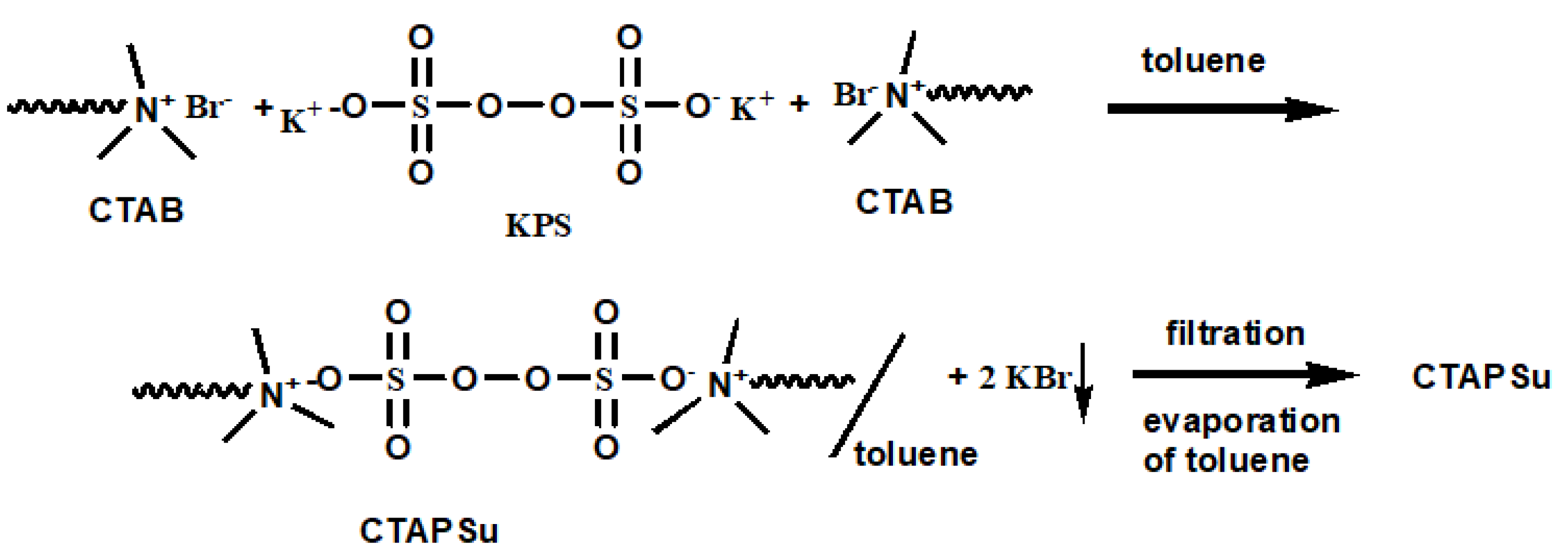
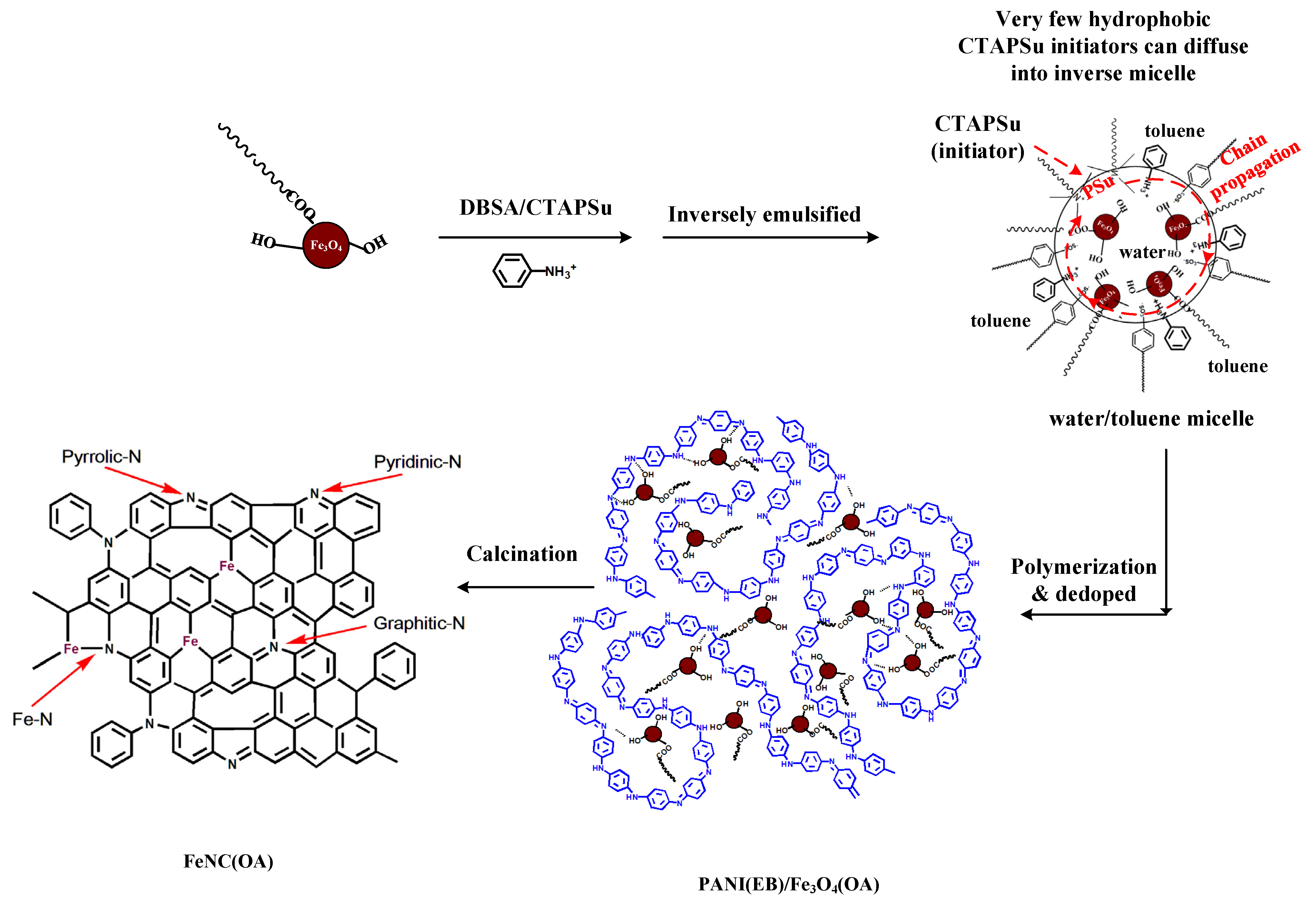
4 and anilinium monomers in surfactant-stabilized micelles of water in affluent toluene. To minimize the number of initiator molecules into the micelles in order to increase the molecular weight (MW) of the resultant PANIs, water soluble KPS (potassium persulfate) initiators are both end-capped with CTAB (cetylammonium bromide), converting it into more hydrophobic CTAPSu (cetylammonium persulfate). In fact, without this transformation, most of the hydrophilic initiators (KPS) would enter into the water micelles, and the system would be similar to that for inverse-suspension polymerization, leading to polymers with a lower MW and reducing the area of PANIs, which can are able to cover by the magnetic particles. Therefore, most of theCTAPSu are soluble in the toluene phase due to the long aliphatic wings on both ends of the molecule and only few molecules will diffuse into the water-containing micelles in which Fe
3O
4 and anilinium monomers are present. Consequently, the polymerization can proceed with only a limited amount of initiators in the micelles to ignite the polymerization, and high-MW PANIs can be obtained, which can firmly cover Fe
3O
4 nanoparticles inside and well-protect the formed iron composites from oxidation after calcination. A nano-Fe
3O
4/PANI composite via regular emulsion polymerization was also prepared for comparison.
The N- and C-doped iron composite before and after calcination at 950 °C in an argon atmosphere were characterized by FTIR (Fourier transform infrared spectroscopy) and X-ray diffraction (XRD) to analyze the composition of the obtained iron compounds (cementite, ferrite, or ferric nitride). We studied the morphologies of N- and C-doped iron-composites before and after calcination by SEM (scanning electron microscopy) and TEM (transmission electron microscopy).
3. Results and Discussion
This section is divided by subheadings. It provides a concise and precise description of the experimental results, their interpretation, as well as the experimental conclusions.
3.1. Subsection
FTIR Spectra
Fe
3O
4 nanoparticles prepared by the sol–gel method clearly showed hydroxyl groups at ~3300 cm
−1 in accordance with
Figure 1a, which did not disappear entirely after esterification with OA, as seen in
Figure 1b. The presence of peaks around 587 cm
−1 revealed the formation of Fe–O bonding; the symmetric and asymmetric stretching of aliphatic methylene and methyl groups of OA was clearly seen at 2920 and 2840 cm
−1.
The prepared Fe
3O
4 nanoparticles were mixed with anilinium monomers before inverse emulsion polymerization. The obtained PANI(ES)/Fe
3O
4 composites were de-doped into PANI(EB)/Fe
3O
4 in NH
4OH(aq), and their FTIR spectra were compared to those of neat PANI(ES) and PANI(EB), respectively, as shown in
Figure 1b. The Fe–O groups were still present in the composites, as shown in
Figure 1b, and the characteristic functional groups of PANI belonging either to ES or to EB, were also observed, even when the preparation was carried out in the presence of Fe
3O
4, indicating that the characteristic functional groups of PANI were not influenced by the presence of Fe
3O
4. However, some interaction occurred between PANI(EB) and Fe
3O
4 particles. For example, peaks belonging neither to neat PANI(EB) nor to Fe
3O
4 were observed at around 3160 cm
−1, as shown in
Figure 1b. Only single peak found for –NH– stretch mode (3417 cm
−1) of PANI(EB) due to the H bonds with the –OH groups of Fe
3O
4, as shown in
Figure 1a. The presence of H bonds between PANI(EB) molecules and Fe
3O
4 nanoparticles can modify the morphology of PANI(EB) in the composites, which will be examined by UV spectra.
3.2. UV–Vis Spectra
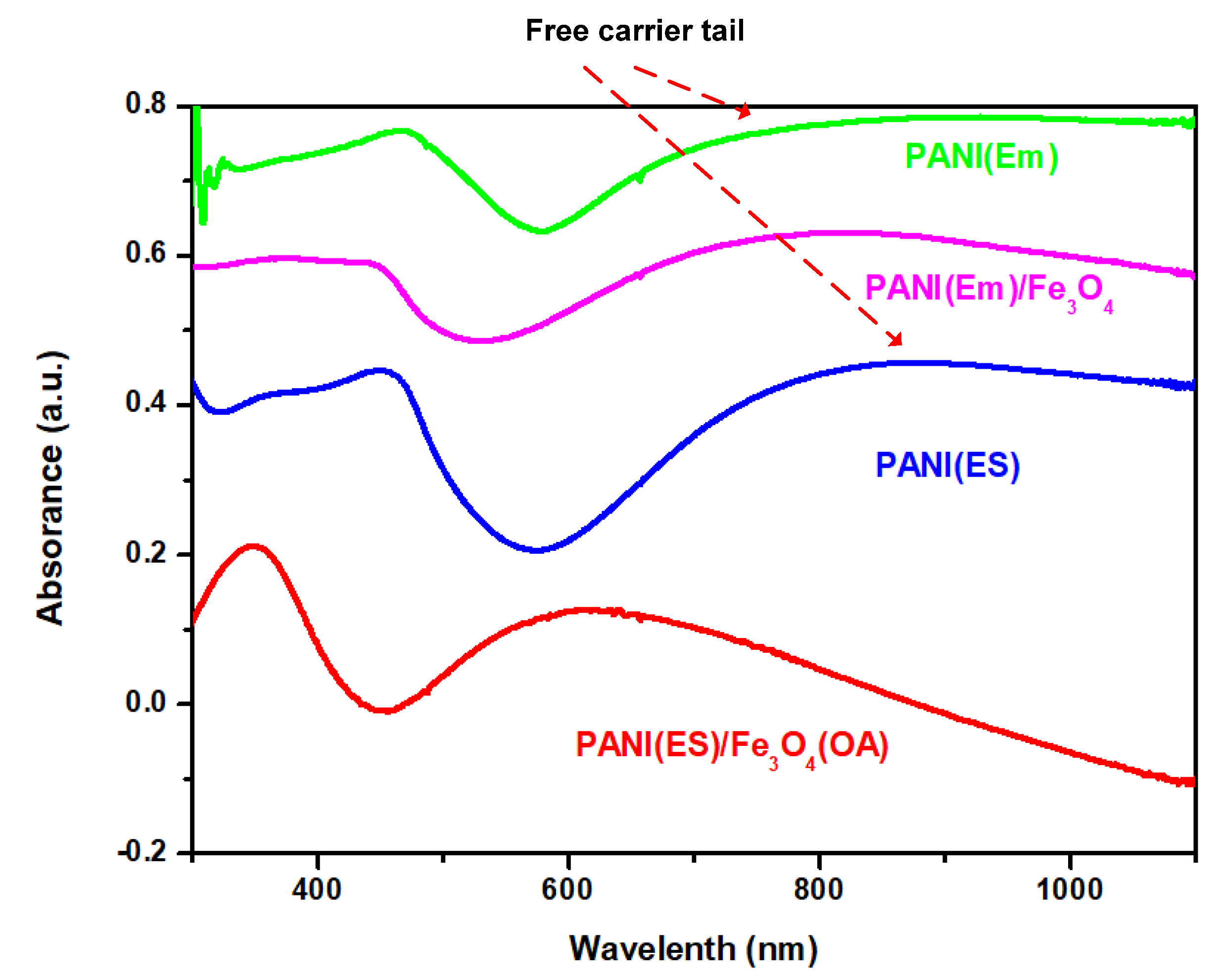
The UV spectra of neat PANI and composites prepared with either common or inverse emulsion polymerization are shown in
Figure 2. For neat PANI(Em) and PANI(ES), the so-called ‘free carrier tail’ [
28,
29], which is related to the increase of the conjugation chain length and super red-shift to the near-IR region due to the more extended PANI molecules, is demonstrated in
Figure 2. After Fe
3O
4 nanoparticles were incorporated in PANI, the tails in the near-IR region decayed and became curved for samples prepared by both regular and inverse emulsion. The bended curves of the composites indicate the shortening of the conjugation (blue shift). The extended PANI molecules recoiled back appearing like random coils than rigid rods. The coiling driving force could originate from the H-bonding between the hydroxyl groups of Fe
3O
4 nanoparticles and the amino groups of PANI. For PANI(Em)/Fe
3O
4 prepared with the regular emulsion approach, the H-bonding mainly occurred on the rigid rod surfaces, and the nanoparticles remained on the surface, as described in
Scheme 2, since the hydrophilic Fe
3O
4 nanoparticles would remain in the water phase rather than penetrate in the core of the micelles where polymerization occurred (
Scheme 2).
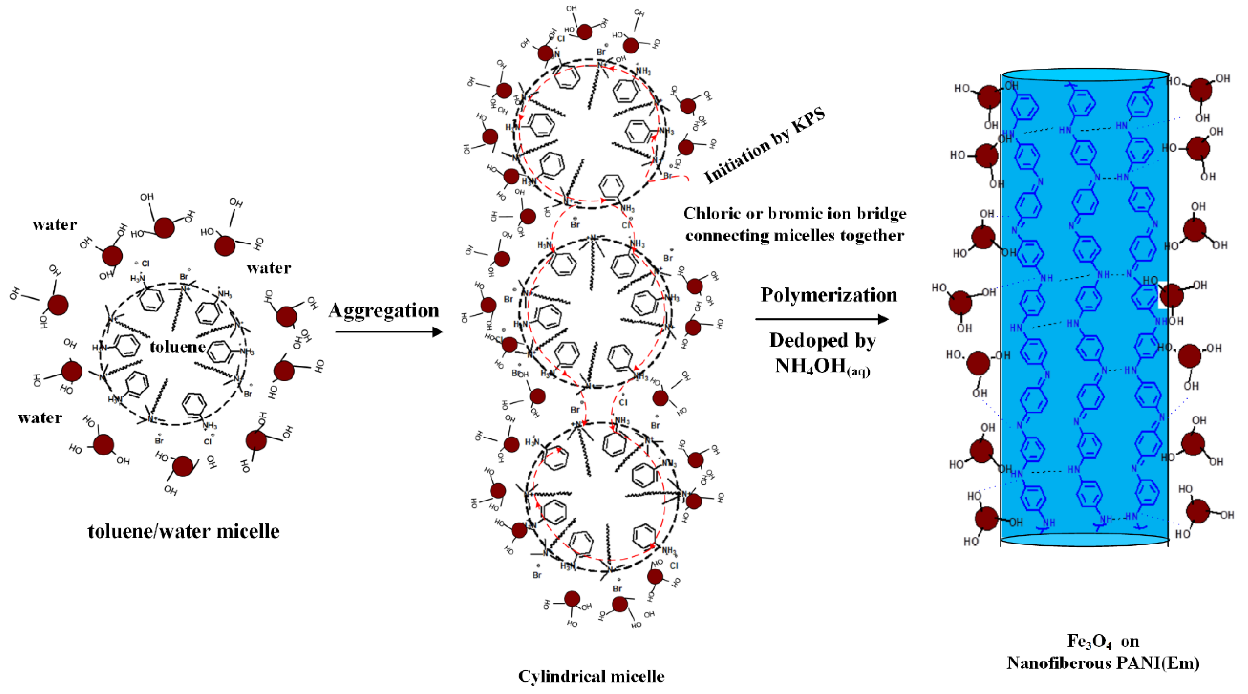
PANI(ES)/Fe
3O
4(OA) prepared with inverse emulsion also demonstrated a blue shift from the near-IR (890 nm) to the visible region (620 nm) for the λ
max, revealing that hydroxylated Fe
3O
4 nanoparticles were able to enter the micelles where they were surrounded by the coiled PANI(ES) molecules after polymerization to de-dope polyaniline producing PANI(EB). The Fe
3O
4(OA) nanoparticles with surface–OH groups and only one oleic tail (based on the molar ratio described in
Section 2.1.4) were capable of staying in the outer area of the micelles, where most of the anilinium monomers were located (
Scheme 3) during the inverse emulsification process, covered by the coiled PANI(ES) after polymerization. Therefore, the significant blue shift of PANI(ES)/Fe
3O
4(OA) in the UV spectrum of
Figure 2 came from the neutralization effect after contact with Fe
3O
4(OA), which turned PANI(ES)/Fe
3O
4(OA) to PANI(EB)/Fe
3O
4(OA), as depicted in
Scheme 3. In contrast, the curve of the UV spectrum of PANI(Em)/Fe
3O
4 prepared via regular emulsion polymerization only demonstrated a slightly bending curve in the near-IR region after the introduction of Fe
3O
4, because the obtained PANI rods were just covered by the Fe
3O
4 nanoparticles, as will be seen and discussed in the following SEM section.
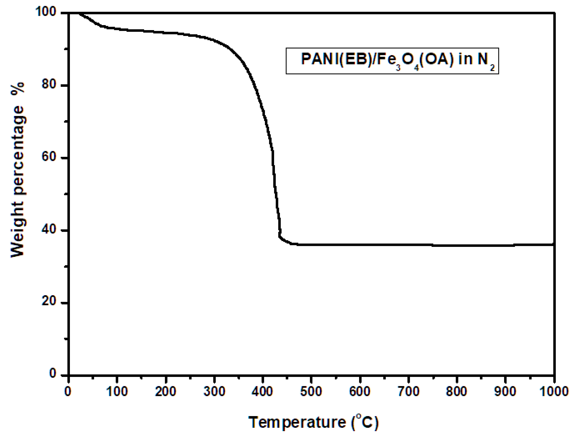
3.3. TGA
The thermal degradation of PANI(EB)/Fe
3O
4(OA) was monitored by TGA. We observed about 5 wt% loss, as shown in
Figure 3, due to the evaporation of water below 100 °C. A not significant weight loss was measured from 100 to 300 °C [
15]. Crosslinking between neighboring PANI(EB) occurred at this stage, leading to the loss of only some H elements without causing significant weight loss as would result from breaking the backbones. After 300 °C, significant thermal degradation of PANI(EB) main chains and alkyl chains of OA occurred, and the matrix started to carbonize by driving some N element off in the form of ammonia and methane. The carbonized matrix became robust Fe, N-doped carbonaceous composites after 500 °C, and weight loss was negligible up to 1000 °C. Eventually, a residual weight of 35% was measured, which is well above the theoretical value of iron, indicating some of the PANI(EB) was retained in the form of a Fe, N-doped composite after calcination, as described in the final portion of
Scheme 3.
3.4. SEM
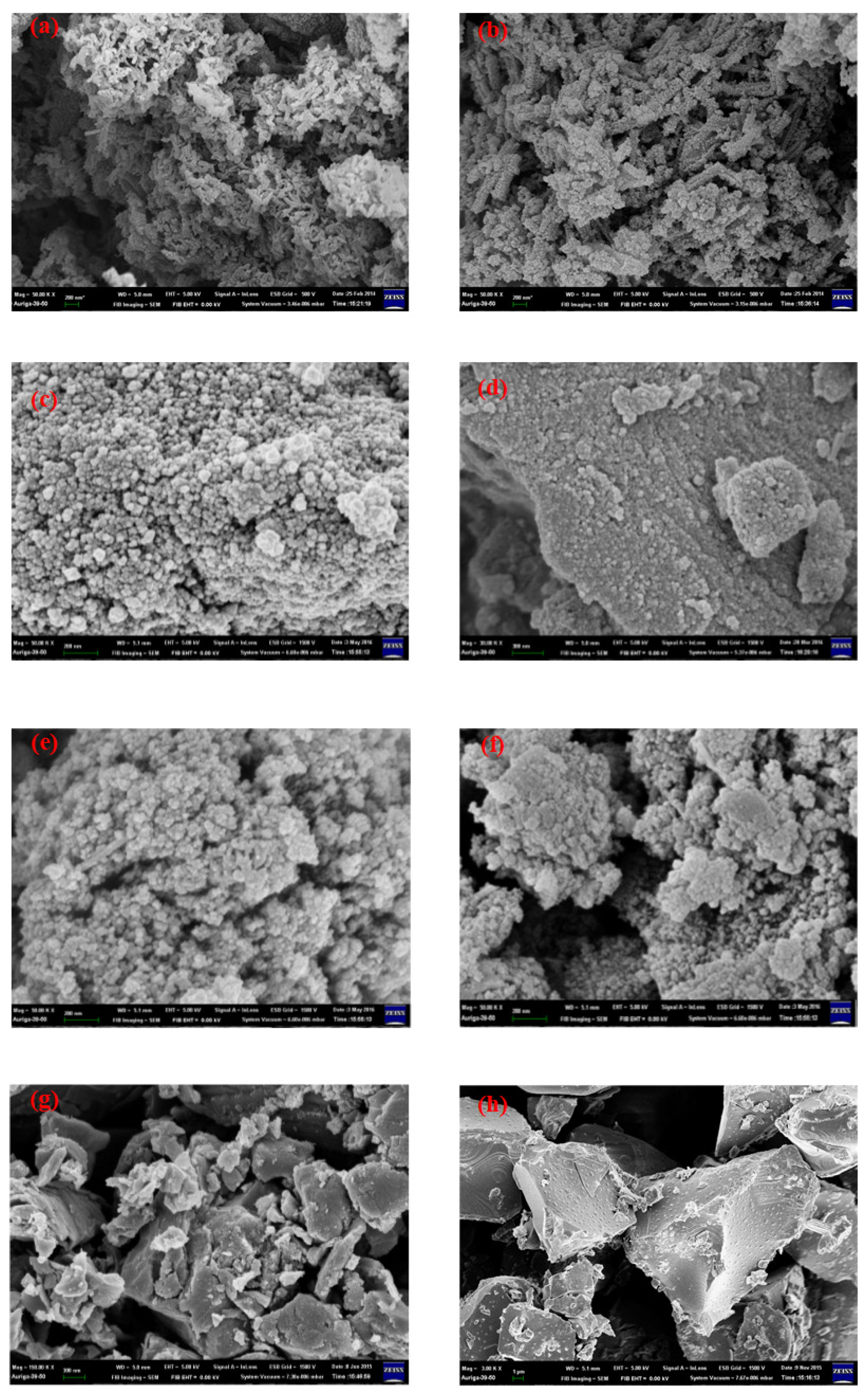
For PANI(EB) prepared with the regular emulsion approach, a nanofibrous morphology was clearly observed in SEM micro-pictures (
Figure 4a). The nanofibrous morphology originated from the interconnection of micelles by counter ions before polymerization [
28], resulting in the rigid-rod morphology after polymerization, which is commonly found in the emulsion polymerization of PANI, as described in
Scheme 1 [
29].
Due to their hydrophilic nature, hydroxylated Fe
3O
4 particles (referring to the FTIR spectrum in
Figure 1) would remain outside the micelles in the water phase before and after the polymerization, covering the rigid-rod surfaces of PANI eventually (
Figure 4b). Comparing the sizes of the PANI nanofibers without and with Fe
3O
4 particles (
Figure 4a,b) present during polymerization, the diameter of the PANI nanofibers increased from 100 to 200 nm when many Fe
3O
4 particles covered on fibers’ surface.
However, PANI(Em)/Fe3O4 obtained from common emulsion was only covered with Fe3O4 nanoparticles, which can be easily converted to ferrite after calcination, and the unprotected ferrite can be easily oxidized into either Fe3O4 or cementite when exposed to the open air; in addition, the lower magnetization can largely decrease the bulk magnetization of the calcined iron composites. In other words, the iron-enriched ferrite composite with a high magnetic moment needs the protection of a calcined PANI covering to prevent the oxidation or the diffusion of carbon into the ferrite matrix, resulting in the formation of cementite. The evidence of the conversion from ferrite to either cementite or oxidized Fe3O4 was provided by the X-ray diffraction patterns of the calcined products.
Both Fe
3O
4 and Fe
3O
4(OA) particles demonstrated a connected pearl-like morphology, as shown in
Figure 4c,d. The strong interaction (mainly H-bonding) between these particles and anilinium monomers in the outer area of the micelles during inverse emulsification allowed the obtained PANI molecules to adopt a curved conformation with a reduced crystalline structure. The rigid-rod morphology was no more seen in either PANI(EB)/Fe
3O
4 or PANI(EB)/Fe
3O
4(OA) and was mostly replaced by particular morphologies, in accordance with
Figure 4e,f and as described in
Scheme 3. The calcined composites (FeNC) demonstrated a largely curved slab-like morphology due to the gradual carbonization of the polyaniline matrix with the proceeding of calcination, which fused the smaller particles into huge slabs, as seen in
Figure 4g.
3.5. TEM Micropictures
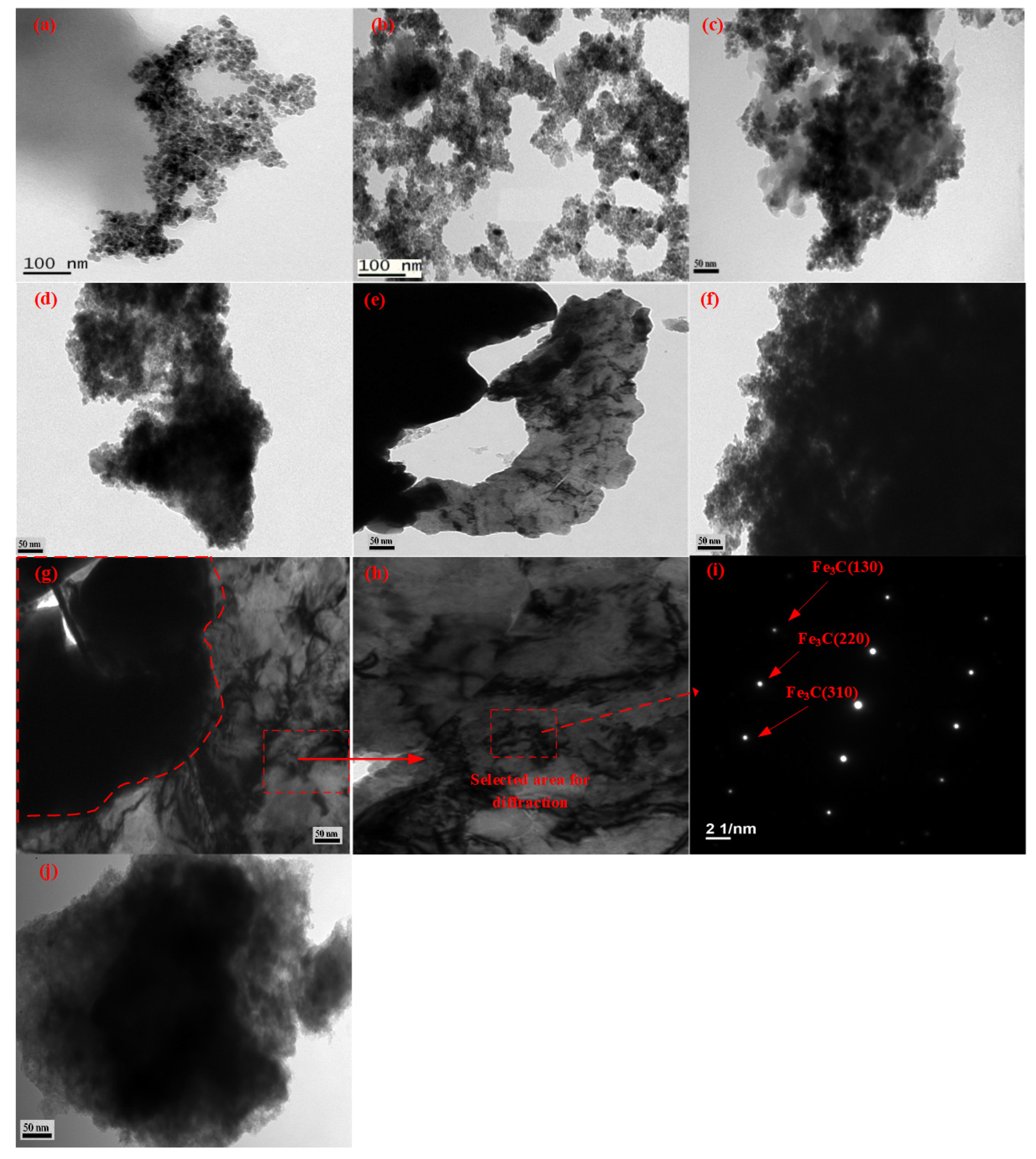
Similar to the SEM micro-pictures in
Figure 4, the TEM micro-pictures of neat Fe
3O
4 and Fe
3O
4(OA) demonstrated the presence of pearl-like nanoparticles with similar sizes, as seen by comparing
Figure 5a with
Figure 5b. The presence of OA during the preparation of Fe
3O
4 seemed to fasten the aggregation of the nanoparticles, as shown in
Figure 5b. The same phenomenon can be seen in
Figure 5c,d for PANI/Fe
3O
4 and PANI/Fe
3O
4(OA) mixtures which were obtained via inverse emulsion polymerization. The graft of OA on Fe
3O
4 (Fe
3O
4(OA)) surfaces stabilized the micelle and allowed more Fe
3O
4 nanoparticles in the micelles. Besides, the swelling micelles resulting from the larger and more stable polymerizing PANI molecules (polymer droplets), prevented the early precipitation of PANI/Fe
3O
4(OA) from the broken polymer droplets, as described in
Scheme 3.
After calcination at 950 °C, all pearl-like Fe
3O
4 particles disappeared and fused into clusters (
Figure 5e,f) due to the carbonization of polyaniline matrix. Possibly, some of the α-Fe would converted to Fe
3C, combining with the carbon provided by PANI during calcination, developing into a veined texture, present around or inside a dark cluster, as shown in
Figure 5e for FeNC. However, for FeNC(OA) (
Figure 5f), almost no veined texture in the dark cluster could be seen after calcination, indicating the formed α-Fe was well mixed with Fe
3C, which has a very dense structure and can effectively hinder O
2 from diffusing into the α-Fe domains and maintain its high magnetic moment.
The density of Fe3C is 7.69 gcm−3, which is almost equivalent to that of α-Fe (7.87 g cm−3), scattering TEM electrons equally. Therefore, most of the α-Fe are staying with some Fe3C in the dark area of TEM pictures of FeNCs, whose vein texture are not perceivable due to the similar electron scattering capability. The two types of iron compounds (α-Fe/and Fe3C) were the dominant species, and less Fe3O4 (density is 5.17 gcm−3) was present after calcination at 950 °C, based on the following discussions on the X-ray diffraction and SQUID spectra.
The morphology of FeNC changed gradually, and more veined textures of Fe
3C appeared after two months in the atmosphere, as observed when comparing
Figure 5e with
Figure 5g or
Figure 5h. The e-diffraction pattern demonstrated in
Figure 5i clearly shows the vein-like textures contributed by Fe
3C. Obviously, the unprotected α-Fe of FeNC could be converted into Fe
3C gradually even at room temperature if it stayed in the atmosphere for enough time. Eventually, the magnetization of FeNC-2 would decrease by sacrificing α-Fe to Fe
3C, which we will discuss in the following X-ray diffraction and SQUID. However, for FeNC(OA), the morphology was almost the same after two months, as seen when we compare
Figure 5f with
Figure 5j. The vein-like morphology around the dark cluster was not significant, as shown in
Figure 5j, indicating that α-Fe was still the dominant species in the dark cluster, maintaining its high magnetic moment. The presence of some Fe
3C in the dark cluster can protect the FeNC(OA) from oxidation during long-term exposure to the open air. It is still possible that some of the α-Fe will be oxidized to Fe
3O
4 after long-time exposure in the open air if the protecting Fe
3C is phase-separated from the dark cluster, leaving the vulnerable α-Fe to O
2, like FeNC and FeNC-2, which will be confirmed and discuss later.
3.6. EDS
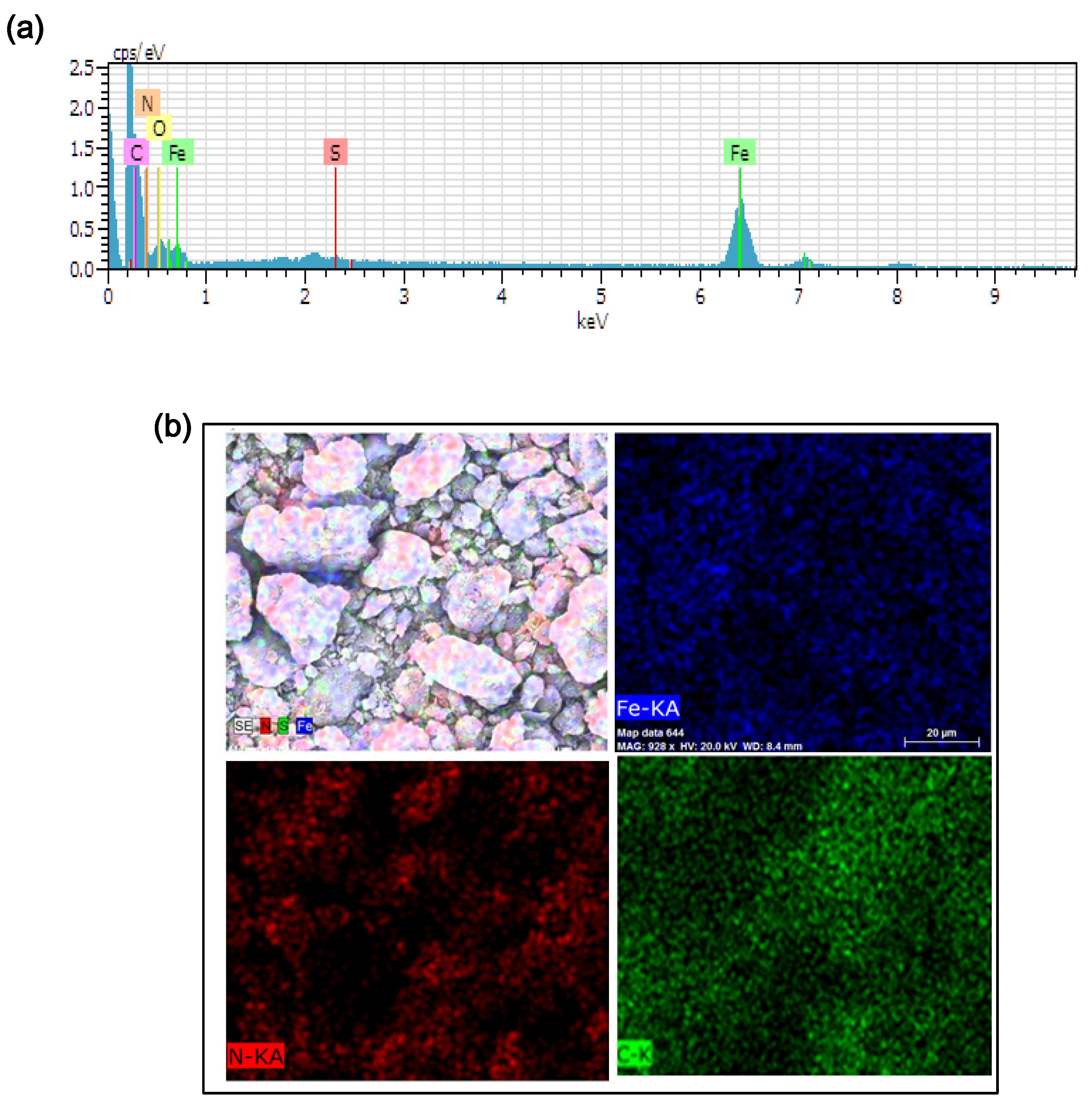
The EDS spectrum of FeNC(OA) and its element mappings are illustrated in
Figure 6a,b, respectively.
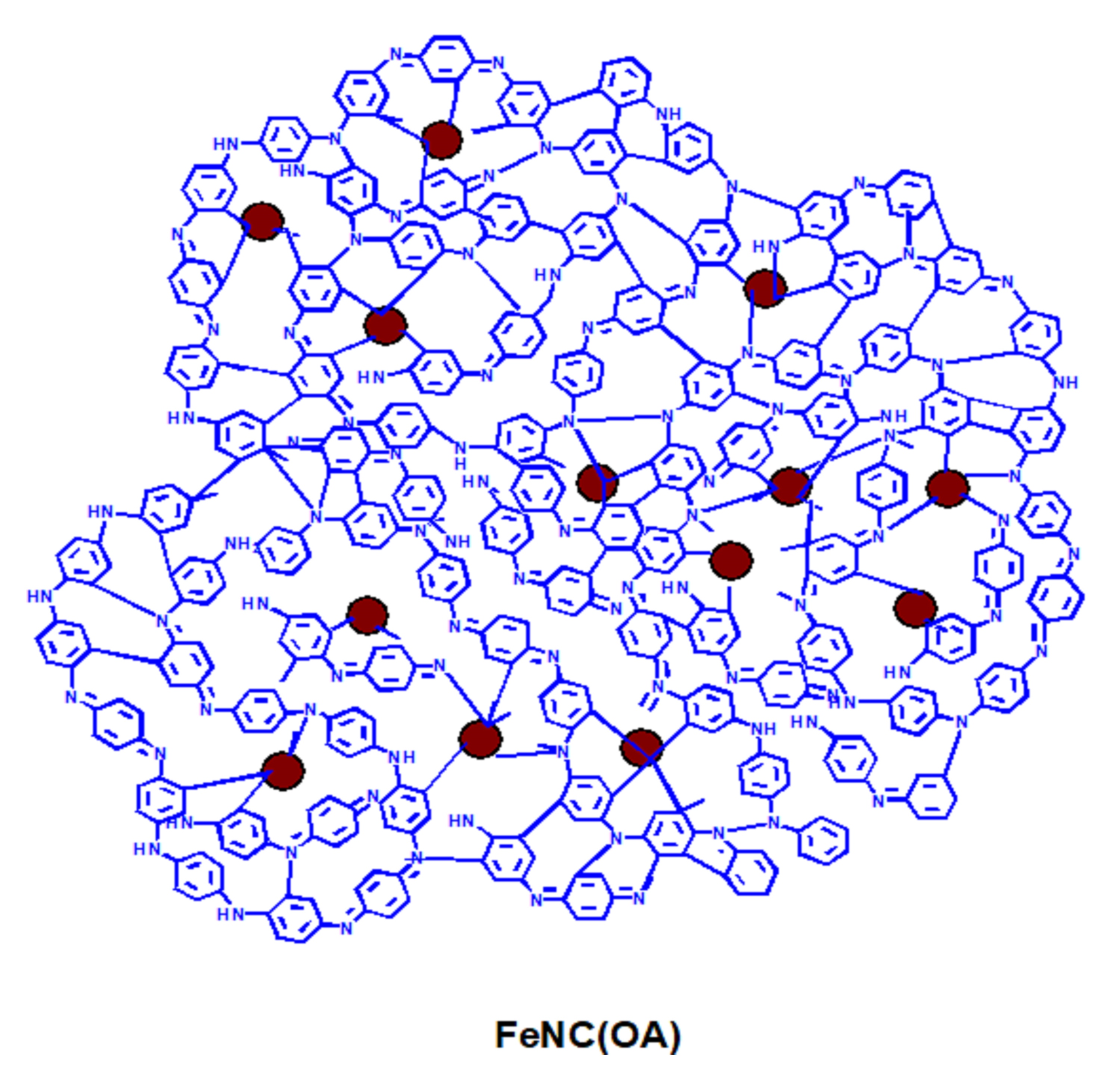
Figure 6a clearly demonstrates the presence of Fe, N, and C elements, C is the dominant element, and both Fe and N peaks are clearly seen. The sulfur element derived from KPS, which was converted to sulfate ion after initiating the polymerization of polyaniline. The element mappings demonstrated in
Figure 6b revealed the presence of Fe, N, and C elements (in the form of α-Fe, Fe
4N, or Fe
3C), uniformly distributed in the carbonaceous matrix. The sulfur in
Figure 6a came from the sulfate salt which formed from APS after initiating the polymerization of aniline salts.
3.7. XRD Patterns
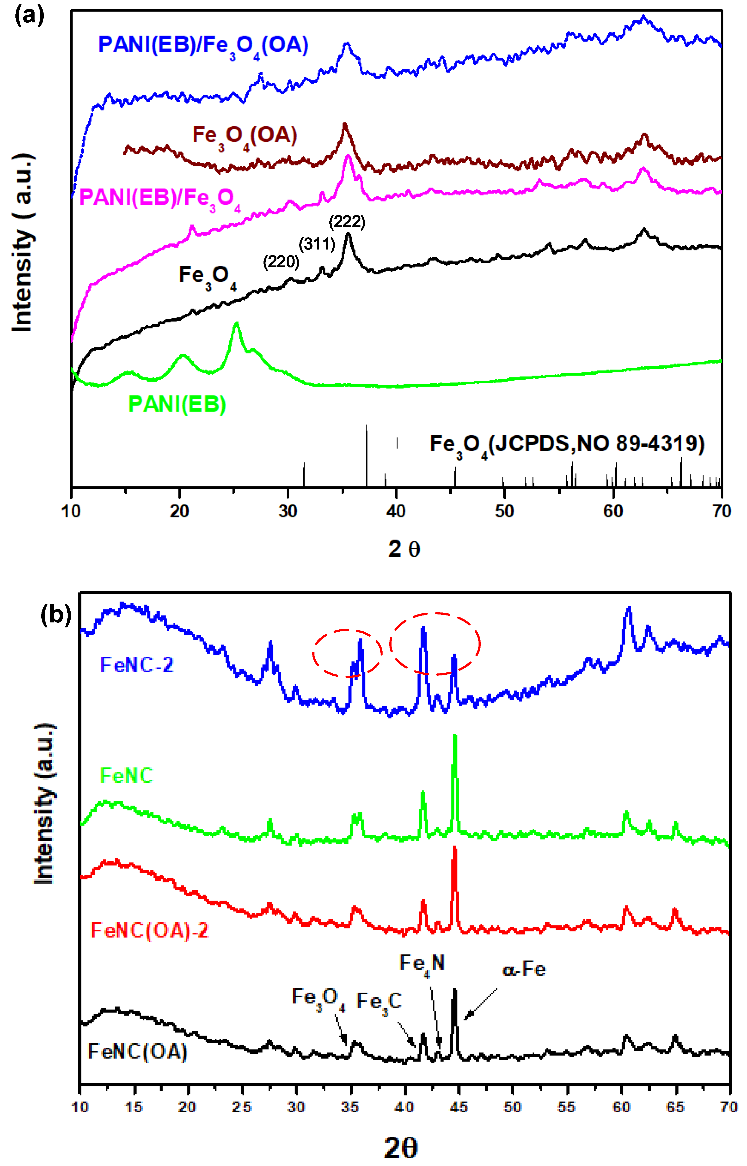
The X-ray diffraction patterns of neat PANI(EB) and nano-Fe
3O
4 compounds are displayed in
Figure 7a, which demonstrates the crystalline patterns of polyaniline and Fe
3O
4 before and after mixing via polymerization. The pattern of neat Fe
3O
4 matches well with the standard pattern of Fe
3O
4 (JCPDS, No. 89-4319); smoother curves were found in the spectrum, indicating higher crystallinity. A clear pattern of peaks smaller than 30° (2θ) were seen for neat PANI(EB) due to the high degree of crystallization. However, peaks with some noise signals were present in the patterns of composite materials, especially after Fe
3O
4 was modified by OA before polymerization. Usually, Fe
3O
4 crystals are easily destroyed when a long-tail molecule like OA is attached on the surface, which might contribute to the imperfect diffracted pattern seen in the spectrum. Besides, no significant characteristic diffraction peak was found for PANI in PANI(EB)/Fe
3O
4(OA) composites, indicating that the crystalline structure of PANI(EB) in the PANI(EB)/Fe
3O
4(OA) was almost entirely demolished by the presence of Fe
3O
4(OA) nanoparticles in the micelles.
Significant peaks at 44° of α-Fe are visible in the X-ray spectra of
Figure 6b after calcination at 950 °C for all iron-nanocomposites, contributing to the excellent high Ms (>120 emu g
−1), which will be discussed later.
These peaks are characteristic diffraction peaks of cementite (Fe
3C) and ferrite (α-Fe), respectively, with a higher Ms than 120 emu g
−1, even reaching 197 emu g
−1 for α-Fe. The magnetic moment contributed from Fe
3C could be retained for a long time due to the perfect, hard crystalline structure, which could effectively prevent further oxidation in the atmosphere. However, α-Fe, which is made of pure Fe element, can easily be oxidized or converted to other iron compounds with weaker magnetization if it stays in the atmosphere for a long time. For example, soft α-Fe can combine with oxygen in the air and become Fe
3O
4 (oxidation) again, and the carbons close to α-Fe can also diffuse into the soft α-Fe matrix and create the harder crystalline structure of Fe
3C. Both types of reactions turn out to be products with a lower magnetic moment compared to α-Fe and would significantly decrease the bulk magnetization. When we compared the X-ray diffraction patterns obtained two months later with the original one (
Figure 7b), we noticed that iron composite prepared with neat Fe
3O
4 (FeNC) could develop into a compound with more Fe
3O
4 and Fe
3C (42°). Based on the TEM micro-pictures (
Figure 5g,h), we found many veined textures developed only by the sides of FeNC-2 after two months.
The TEM picture (
Figure 5j) shows that no significant Fe
3C precipitated from the matrix compound during two month in the air, indicating some hard, perfect crystallized Fe
3C mixed with α-Fe can effectively prevent oxidation from losing its magnetic moment.
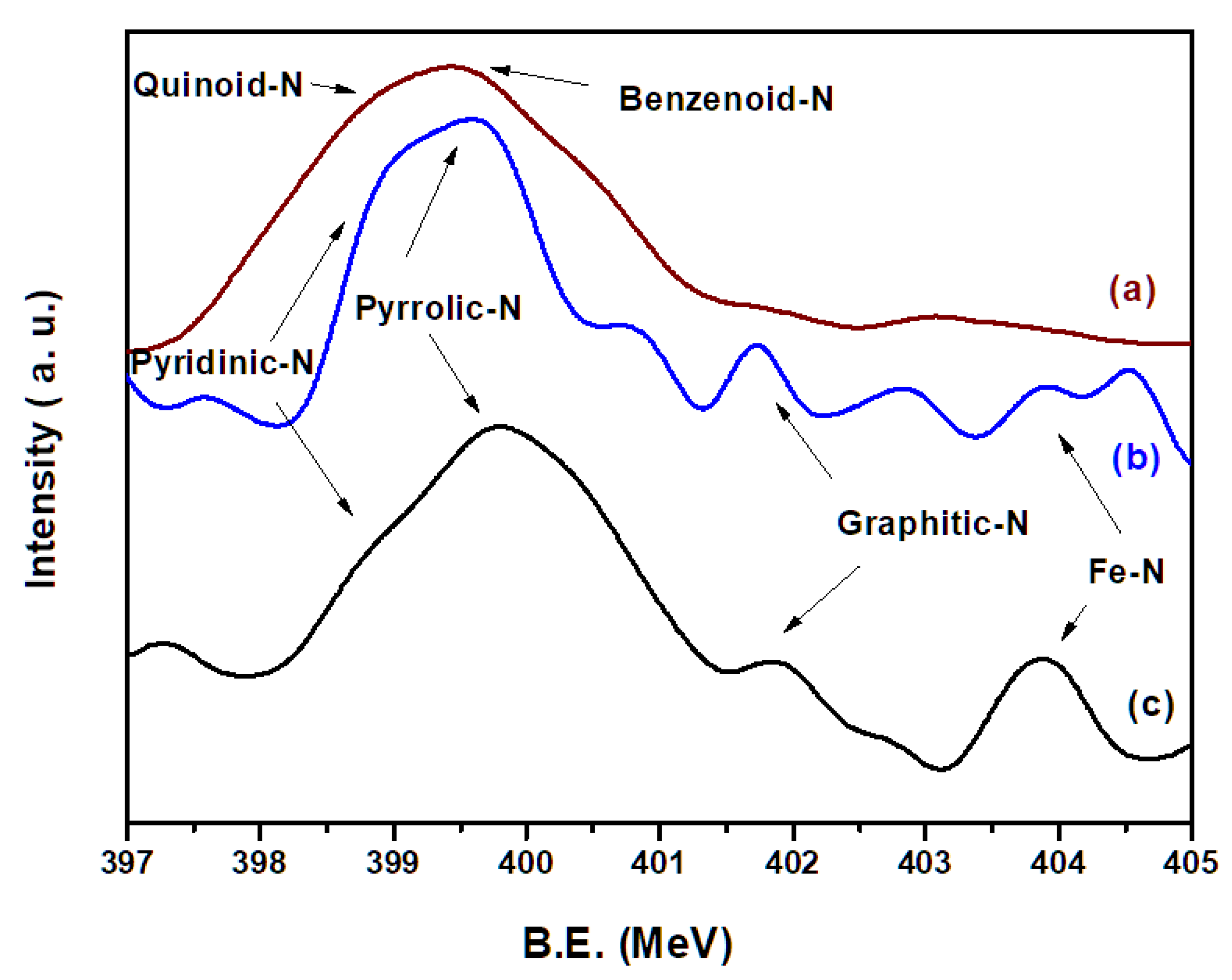
3.8. XPS Spectra
The XPS of N
1s of neat PANI(EB), FeNC, and FeNC(OA) are illustrated in
Figure 8 and characterize the possible N-containing products after calcination. In
Figure 8a, no complicated N-related groups are seen, but quinoid-N and benzenoid-N are observed, which are connected alternatively to become PANI(EB). However, various N-containing groups [
30,
31,
32] include pyridinic N (six-membered ring present in the edge), pyrrolic N (five-membered ring present on the edge), graphitic N (six-membered ring present in the middle of graphene-like matrix), and Fe–N emerged after calcination at 950 °C, and are depicted in the last portion of
Scheme 3. Both FeNC (
Figure 8b) and FeNC(OA) (
Figure 8c) contain a large quantity of pyrrolic N and less graphitic N.
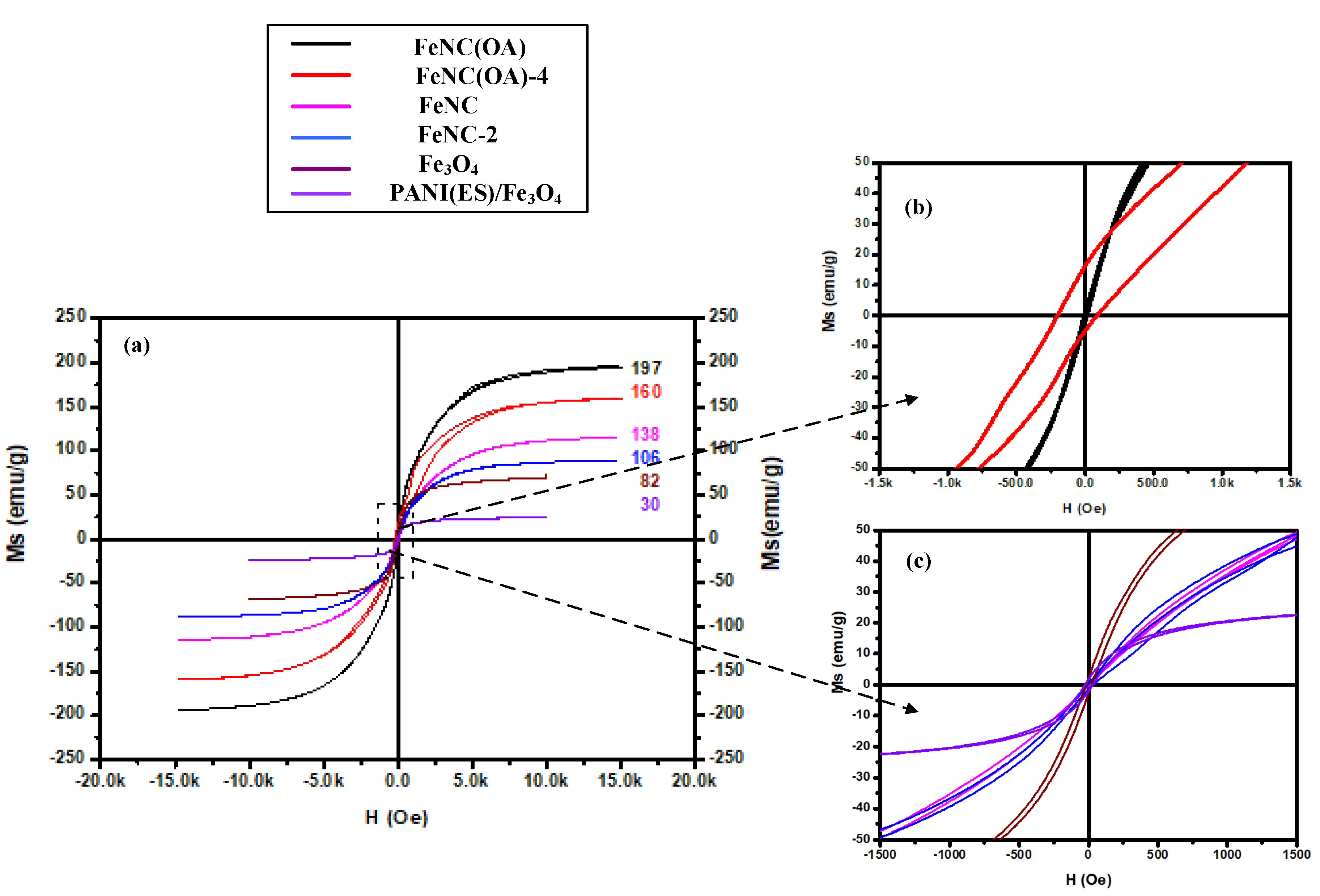
3.9. SQUID Spectra
Calcination above 900 °C for the blended mixtures of polyaniline and nano-Fe3O4 provided enough energy for the movement of various elements including Fe, N, C, and O. The arrangement of these elements created a new form of iron-related compounds. All of them demonstrated much higher Ms than the original Fe3O4 and contributed to the high Ms due to the presence of Fe3C, Fe4N, and α-Fe in the calcined composites.
As expected, FeNC and FeNC(OA), which were obtained from the calcination of PANI(EB)/Fe
3O
4 and PANI(EB)/Fe
3O
4(OA) at 950 °C, respectively, demonstrated high saturated magnetization of 138 and 197 emu g
−1 compared to 82 emu g
−1 of neat Fe
3O
4 and 30 emu g
−1 of PANI(ES)/Fe
3O
4, in accordance with
Figure 9a. The high magnetic moment of FeNC and FeNC(OA) derived from the formation of both α-Fe and Fe
3C, as already confirmed in the section of X-ray diffraction patterns. However, the Ms of FeNC decayed by 23.2%, from 138 to 106 emu g
−1 in the air within two months, according to
Figure 9a. For FeNC(OA), the decay was about 18.7%, from 197 to 160 emu g
−1, still less than that of FeNC (23.2%) after a longer time (four months) at room temperature.
Regularly, the steep loss of magnetic moment of α-Fe derived from the oxidation in air when it could not convert to other protective iron compounds, and low-magnetic-moment iron oxides became the main products. For either FeNC or FeNC(OA), a not significant increase of Fe
3O
4 was observed after two and four months in air, respectively (i.e., FeNC-2 and FeNC(OA)-4) from their X-ray diffraction spectra. Therefore, the magnetic moment was lost mostly due to the transformation from high-magnetic-moment α-Fe to Fe
3C, since not significant oxidation can occur in the air under the protection of the carbonized PANI. In
Figure 7b of the X-ray pattern, an increasing peak of Fe
3C and a decreasing peak of α-Fe were observed only for FeNC-2, whereas such phenomenon was not observed for FeNC(OA)-2 which still had a high magnetic moment two months later. For FeNC-2, more newly formed Fe
3C precipitated from the matrix (
Figure 5g). Hard materials like Fe
3C mixed with FeNC(OA)-2 can effectively prevent further carbon diffusion into the inner α-Fe matrix and stop the advanced conversion to Fe
3C. In other words, attaching a long alkyl chain to the surface of Fe
3O
4 nanoparticles via the inverse emulsion polymerization of PANI enhanced and stabilized the magnetization of the resultant C, N-doped iron compounds (FeNC(OA)). They successfully developed into dominant α-Fe via calcination under the protection of the surrounding PANI molecules and maintained a high magnetic moment in air under the protection of some hard and stable Fe
3C.
All samples demonstrated perfect superparamagnetivity with slight hysteresis and not significant residual magnetivity, as shown in
Figure 9a. Though some of the magnetization could be maintained after four months for FeNC(OA)-4, hysteresis was enhanced according to
Figure 9b (upper inset diagram of
Figure 9a); hysteresis was smaller for FeNC-2, as shown in
Figure 9c (down inset diagram of
Figure 9a).


 and
and 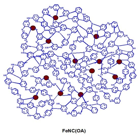


