Output Pulse Characteristics of a Mamyshev Fiber Oscillator
by
 , ,
, ,
Haili Han
1, 
Nan-Kuang Chen
1,*,
Liqiang Zhang
1,
Yanru Xie
1,
Zhen Tian
1,2,
Yicun Yao
1,
Yuanchuan Huang
1 and
Xia Zhang
1 1
Key Laboratory of Optical Communication Science and Technology of Shandong Province, School of Physics Science and Information Technology, Liaocheng University, Liaocheng 252000, China
2
State Key Laboratory of Information Photonics and Optical Communications, Beijing University of Posts and Telecommunications, Beijing 100876, China
*
Author to whom correspondence should be addressed.
Photonics 2021, 8(12), 590; https://doi.org/10.3390/photonics8120590
Submission received: 19 November 2021
/
Revised: 15 December 2021
/
Accepted: 16 December 2021
/
Published: 18 December 2021
(This article belongs to the Special Issue Mode Locked Fiber Laser)
Abstract
:The dependence of the output pulse characteristics of a Mamyshev fiber oscillator on cavity parameters is investigated in detail. We analyze the change in pulse spectrum bandwidth, pulse duration, dechirped pulse duration and chirp with the change in fiber group velocity dispersion, fiber nonlinearity, gain, and filters by putting forward a numerical model. In particular, as one of the most important components, the effect of filters bandwidth and the central wavelength interval between them is discussed. The passive fibers are classified into two kinds according to their locations in the cavity, which are the one before the gain fiber and the one after the gain fiber. Numerical simulation results show that a wide spectrum can be obtained by increasing the nonlinearity of the second passive fiber, while the change in nonlinearity of the first passive fiber has a weak effect on spectrum broadening. A wide spectrum could also be obtained by increasing the nonlinearity or the small-signal gain coefficient of the gain fiber. A Yb-doped Mamyshev fiber oscillator is demonstrated. The results show the increase in pump power, which agrees reasonably well with the numerical simulation results.
1. Introduction
Mode-locked ultrashort-pulsed fiber lasers have the advantages of simple structure, high beam quality, narrow pulse width, and so on. They are widely used in the fields of high-precision machining, aerospace, biomedical science, and so on. The remarkable progress of the performance of mode-locked fiber lasers results from advances in understanding and controlling nonlinear pulse evolution in the cavity [1]. Typically, pulse energy increases with the increase in net group velocity dispersion (GVD) of the laser cavity. According to the net GVD, various nonlinear pulse evolution mechanisms have been suggested, including solitons [2] in negative dispersion lasers, dispersion-managed solitons [3], self-similar pulses in cavities with net dispersion close to zero [4,5], and dissipative solitons in all-normal-dispersion cavities [6]. The pulse energy increases from 0.1 nJ to tens of nJ, which is finally limited by a nonlinear phase shift of about 10 π. Another key component of a mode-locked fiber laser is the saturable absorber, which introduces a power-dependent loss into the cavity to narrow the pulse. At present, there are two kinds of saturable absorbers used in fiber lasers. One is material-based saturable absorber, such as semiconductor saturable absorber. However, in high-power fiber lasers, material-based saturable absorbers are vulnerable to damage [7]. The other one is the equivalent saturable absorber realized by using the nonlinear effect in the optical fiber, such as nonlinear polarization rotation (NPR) [8] or nonlinear loop mirror [9]. The transmission-intensity curve of nonlinear polarization rotation and nonlinear loop mirror do not increase monotonically, which usually leads to pulse instability and multi-pulses [1]. The accumulation of excessive nonlinear phase shift and the lack of perfect saturable absorbers limit the development of environmentally stable high-energy ultrashort pulse laser.
In the past few decades, a new type of Mamyshev fiber oscillator has shown great potential in improving pulsed fiber laser performance [10,11,12]. The working principle of a Mamyshev fiber oscillator is based on two offset filters. Pulses filtered by the first filter experience self-phase modulation when propagating in the fiber, which results in the broadening of the spectrum. Only pulses with high peak intensity can produce sufficient spectrum broadening to be transmitted through the second offset filter. Thus, a step transfer function is produced, which passes high-intensity pulses while those pulses below a certain intensity threshold are blocked. Compared with the traditional mode-locked fiber laser, Mamyshev oscillators have many advantages. First, it is less vulnerable to damage than the material saturable absorber. Second, as of recent, only pulsed fiber lasers mode-locked by NPR deliver pulses rival solid-state oscillator. However, NPR is highly sensitive to the random birefringence of the fiber, which makes it unsuitable for widespread use. The Mamyshev oscillator can be constructed with all polarization-maintaining (PM) fibers; thus, it is possible to build an environmental-stable resonator. Third, the Mamyshev oscillator is tolerant towards the high nonlinear phase shift, which is crucial for high single pulse energy. These advantages make the Mamyshev oscillator extremely attractive for applications.
The idea of a mode-locked laser based on offset filters was proposed very earlier [13], but did not receive wide attention at that time. In 2008, M. Rochette et al. experimentally demonstrated the operation of a pulsed fiber laser based on this concept [10]. However, the laser source could only emit bursts of pulses with an uncontrollable pulse separation. In 2015, an improved version of an environmentally stable Yb-doped fiber Mamyshev oscillator was reported, which generated laser pulses with energy of 2.8 nJ [11]. Subsequently, the characteristics of an Mamyshev oscillator have been widely studied, and the performance of the output pulses has been gradually improved [14,15,16,17,18,19,20,21]. By inserting a highly nonlinear crystal fiber into the cavity, few-cycle pulses with ~400 nm ultra-broad spectrum are obtained from a Mamyshev oscillator [17]. T. Wang et al. investigated the possibility of obtaining high-energy pulses in an all-fiber Mamyshev oscillator, and a single-pulse energy of 83.5 nJ was achieved [18]. Using single-polarization, large-mode-aera photonic crystal fibers, pulses with an average pulse power of 9 W were obtained, with the peak pulse power of 13 MW [19].
The Mamyshev oscillator has shown excellent potential in improving pulse performance. However, the research on the design of the oscillator, i.e., the influence of oscillator parameters on the output pulse characteristics, still remains insignificant. In 2021 [22], the starting dynamic of a linear Mamyshev oscillator was investigated, and the influence of filter separation on laser behavior was studied. Very recently [23], the possibility of using various gain-switched seed laser pulses and fibers to build a low-cost, all-fiber Mamyshev regenerator scheme was numerically investigated, which provided guidance for the designing of pulse-on-demand picosecond scale fiber sources. The performance of a Mamyshev oscillator is related to the cavity parameters, such as the fiber specification, gain, bandwidth of the filter, and so on. It is necessary to analyze the influence of these parameters on the laser pulse. Furthermore, spectral broadening is essential in a Mamyshev oscillator, owing to the existence of the two offset filters. It is important to discuss the factors which affect spectrum broadening. In this paper, the theoretical model of a Mamyshev oscillator is established, and stable pulses can be obtained by reasonably setting the oscillator parameters. The dependence of output pulse spectrum bandwidth, pulse duration and chirp on fiber dispersion, nonlinearity, small-signal gain coefficient of the gain fiber, and filter bandwidth is investigated numerically. Experimental results from a Yb-doped Mamyshev fiber oscillator are presented, which show agreement with the simulation results.
2. Theoretical Model
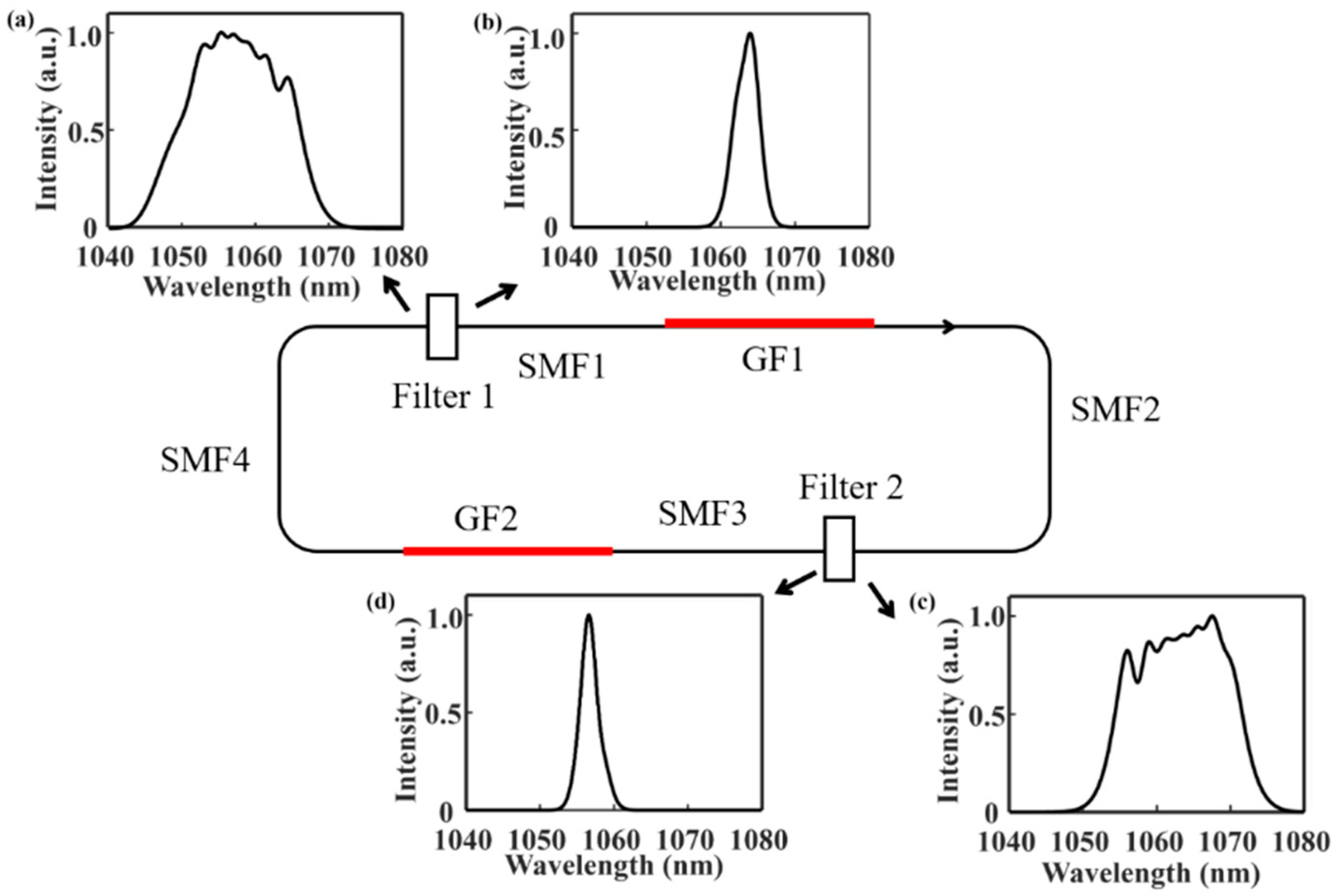
Figure 1 gives the proposed model of the Mamyshev fiber oscillator. The oscillator is composed of two arms. Each arm consists of one band pass filter (Filter 1/Filter 2): the first segment of a passive fiber (SMF1/SMF3) and a gain fiber (GF1/GF2), and the second segment of passive fiber (SMF2/SMF4). The four segments of passive fibers can be classified into two kinds according to their locations. One is a passive fiber before gain fiber, namely SMF1 and SMF3. The other one is the passive fiber after gain fiber, namely SMF2 and SMF4. The output is taken after SMF2. A Gaussian-shaped pulse was chosen as the seed pulse, which is injected into the cavity through Filter 1. The central wavelength of these two filters were set to be 1056.3 nm and 1063.8 nm, respectively, with an interval of 7.5 nm. The 3 dB bandwidths are both set to be 4 nm.
Pulse propagating in the fibers is described by the Ginzburg–Landau equation:
where is the slowly varying envelope of the electric field. is the propagating coordinate, and is the time in a frame of reference moving with the group velocity. represents the group velocity dispersion parameter, and denotes the nonlinear coefficient. is the gain coefficient for the gain fiber. and are the small-signal gain coefficient and saturation energy, and is related to the gain bandwidth of the gain fiber. The function of the filters are taken into account by multiplying the electric field by the Gaussian transmission profile in the frequency domain. The group velocity dispersion, the nonlinear coefficient, and the length of each segment of the passive fiber are set to be 0.0404 ps2/m, 3 w−1 km−1, and 0.5 m initially. The gain bandwidth of the gain fiber is 60 nm, centered at 1060 nm. The Ginzburg–Landau equation is solved by the split-step Fourier method. In the simulation, the dependence of pulse characteristic on cavity parameters, including fiber group velocity dispersion, nonlinear coefficient, small-signal gain coefficient, and filter bandwidth, is investigated.
3. Simulation Results and Discussion
By appropriately setting of the oscillator parameters, stable single-pulse operation can be achieved. Figure 1 shows the spectra at different locations of the Mamyshev fiber oscillator. The pulse spectrum is narrowed after passing through Filter 1 (Figure 1a), which is then amplified and broadened in SMF1, GF1, and SMF2 (Figure 1b). After passing through Filter 2, the spectrum is narrowed again (Figure 1c), and broadened in the following SMF3, GF2, and SMF4 (Figure 1d).
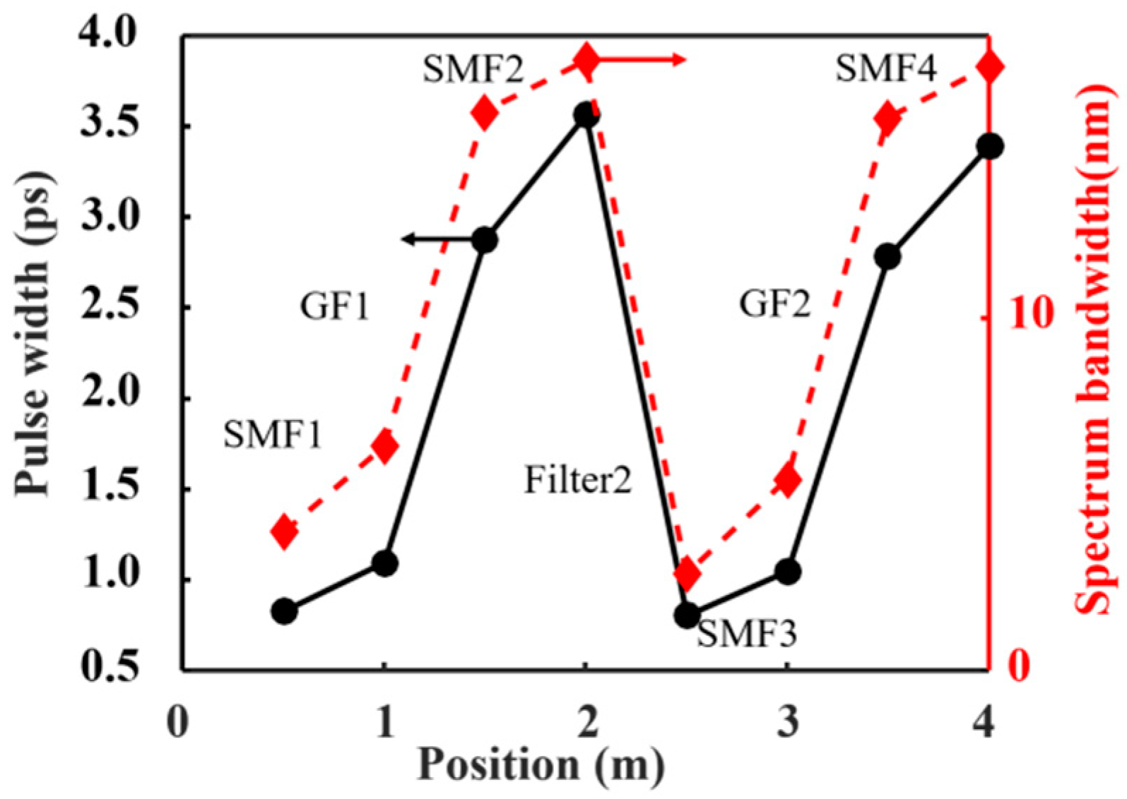
Figure 2 gives the evolution of the 3 dB spectrum bandwidth and pulse duration. The spectrum bandwidth and pulse duration are narrowed after passing through the filter (Filter 1/Filter 2), which are then broadened in the subsequent first segment of passive fiber SMF1 (SMF3), gain fiber GF1 (GF2), and the second segment of passive fiber SMF2 (SMF4). It is worth noting that the broadening of spectrum and pulse duration is realized mainly in the gain fiber in Figure 2. In fact, broadening in the second segment of passive fiber, i.e., SMF2 (SMF4) is related to the nonlinearity of the fiber. If the nonlinear coefficient of the second segment passive fiber is set to be a high value (for example 27 w−1 km−1), the spectrum and pulse will broaden quickly.
3.1. Dependence of the Pulse Characteristics on Cavity Parameters
The pulse characteristics are related to the laser parameters. The spectral bandwidth and pulse duration are calculated under different situations.
3.1.1. Fiber Dispersion
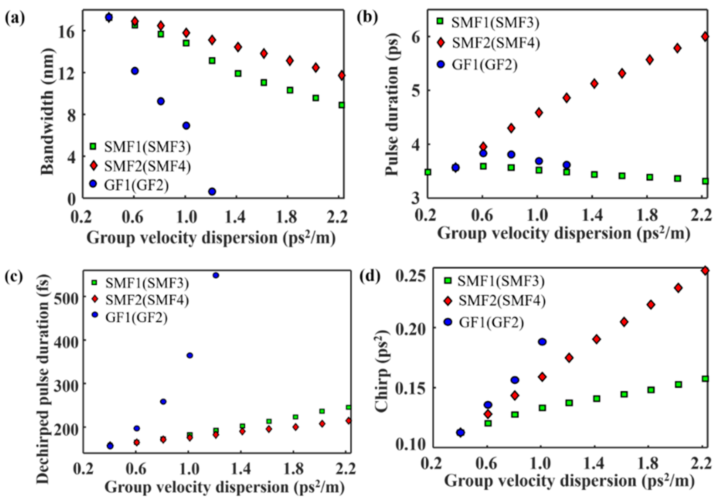
Figure 3 illustrates the simulation results with the increase in fiber dispersion. In the simulation, the length of the fiber remains unchanged, while the value of dispersion is changed. With the increase in fiber dispersion, the spectral bandwidth decreases (Figure 3a), while the dechirped pulse duration increases (Figure 3c). In order to obtain a wide spectrum, it is useful to decrease the fiber group velocity dispersion. In fact, the spectrum could be effectively broadened in dispersion-decreasing fiber [24,25,26]. Pulse duration increases with the increase in SMF2 (SMF4) dispersion. On the other hand, when the dispersion of SMF1 (SMF3) and gain fiber GF1 (GF2) increase, the pulse bandwidth does not change significantly (Figure 3b). As can be seen from Figure 3d, the pulse chirp increases with the increase in fiber dispersion. Here, the pulse chirp is defined as the magnitude of anomalous dispersion required to dechirp the pulse to its maximum peak power [24].
3.1.2. Fiber Nonlinearity
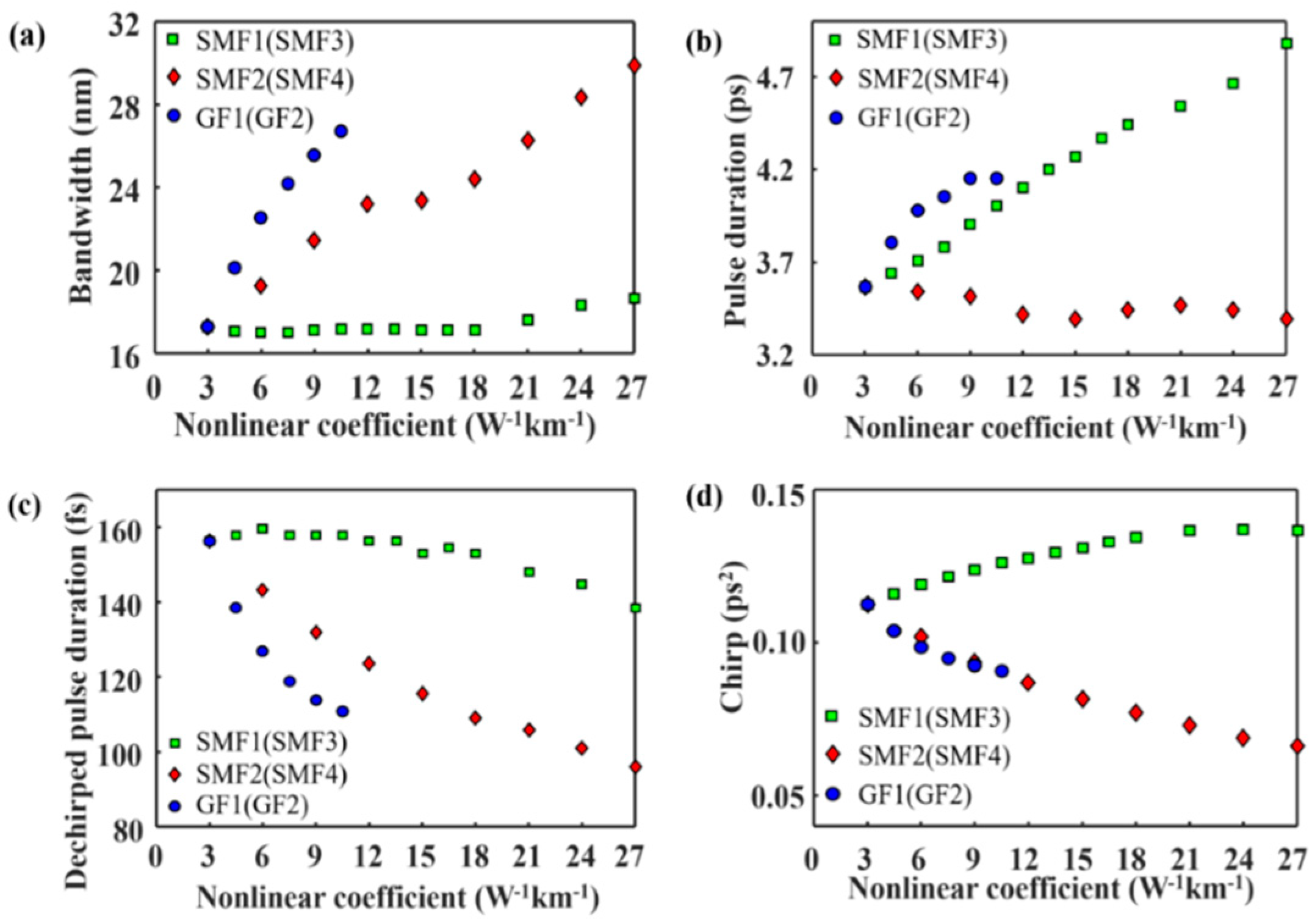
In the simulation, the fiber nonlinearity is changed by changing the value of nonlinear coefficient, while the length of fibers remains unchanged. As shown in Figure 4, when the nonlinear coefficient of the first segment of passive fiber (SMF1/SMF3), the gain fiber (GF1/GF2), and the second segment of passive fiber (SMF2/SMF4) are changed, the spectral bandwidth and pulse duration show different characteristics. When the nonlinear coefficient of SMF1 (SMF3) is increased, the spectrum bandwidth is almost unchanged. However, when the nonlinear coefficient of the GF1 (GF2) and SMF2 (SMF4) is increased, the spectrum bandwidth increase significantly (Figure 4a). In order to obtain pulses with a wide spectrum, it is effective to increase the nonlinear coefficient of the gain fiber or the second segment of passive fiber. The pulse duration increases with the increase in the nonlinear coefficient of SMF1 (SMF3) or GF1 (GF2), while fluctuating in a small range in the case of SMF2 (SMF4). In Figure 4c, the dechirped pulse duration decreases with the increase in the nonlinear coefficient of SMF2(SMF4) or GF1 (GF2), which agrees with the increase in the spectral bandwidth. From Figure 4d, we can see that the pulse chirp is inversely proportional to the SMF2 (SMF4) or GF1 (GF2) nonlinear coefficient, while proportional to the SMF1 (SMF3) nonlinear coefficient.
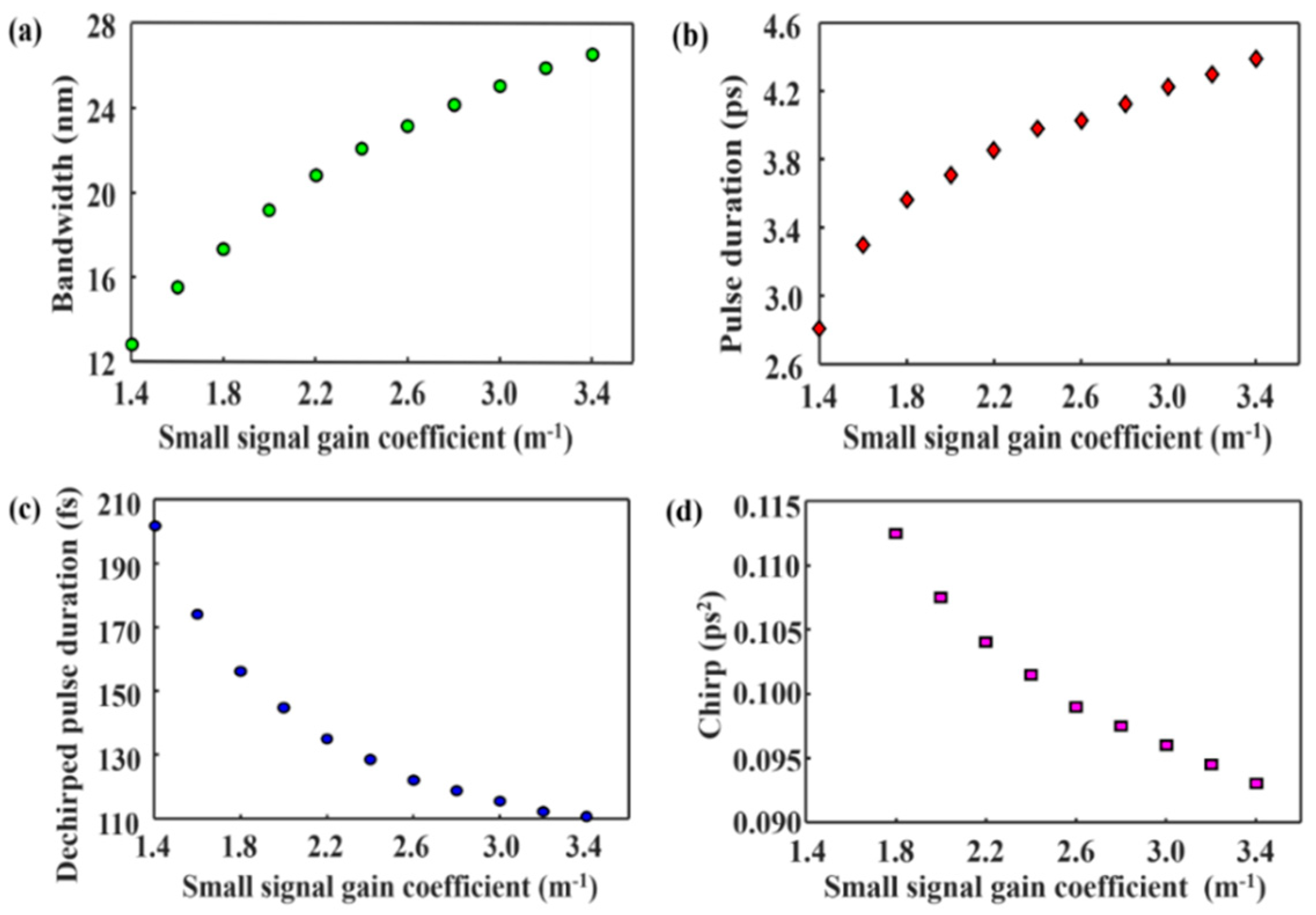
3.1.3. Gain Coefficient
As shown in Figure 5, the spectral bandwidth and pulse duration increase with the increase in the small-signal gain coefficient. Similar to the situation of SMF2(SMF4) or the GF1 (GF2) nonlinear coefficient, the dechirped pulse duration and chirp decrease with the increase in the small-signal gain coefficient.
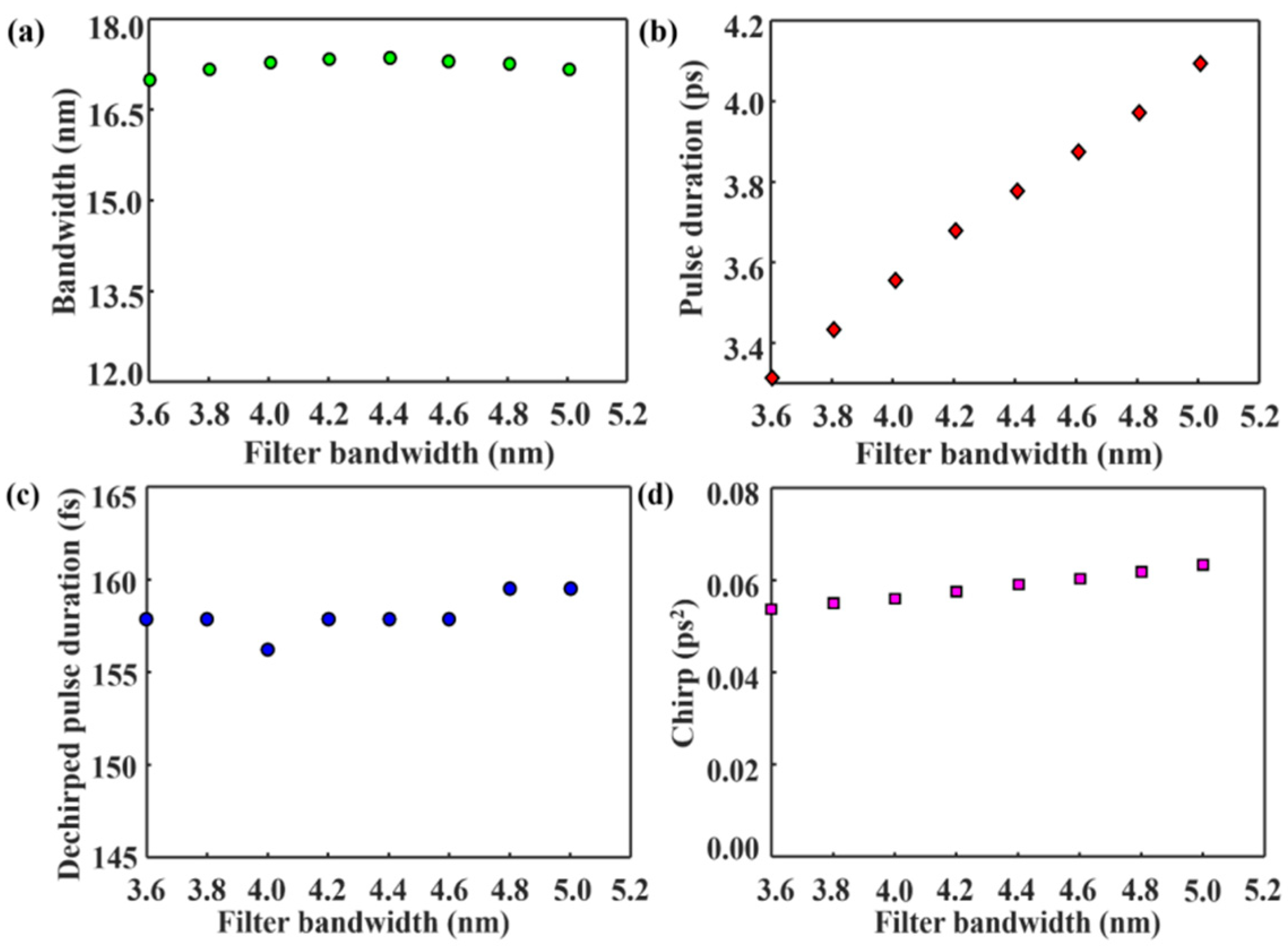
3.1.4. Filter Bandwidth
Figure 6 gives the dependence of pulse characteristics on the filter bandwidth. When the filter bandwidth increases from 3.6 nm to 5.0 nm, the spectrum 3 dB bandwidth varies between 17.02 nm and 17.35 nm, while the pulse duration increases linearly from 3.32 ps to 4.10 ps, respectively. As shown in Figure 6c,d, the dechirped pulse duration fluctuates between 156.25 fs and 159.51 fs, while the pulse chirp increases slightly from 0.054 ps2 to 0.063 ps2.
The effect of the central wavelength interval between these two filters has also been analyzed. The wavelength interval is changed while all the other parameters remain unchanged. When the interval increases from 6.36 nm to 8.71 nm, the pulse duration decreases from 3.72 ps to 3.25 ps. The variation ranges in spectrum, dechirped pulse duration, and pulse chirp are calculated as 0.9 nm, 6.52 fs, and 0.002 ps2, respectively.
3.2. Summary of the Effect of Parameters
First, a wide spectral bandwidth can be obtained by increasing the nonlinear coefficient of the GF1 (GF2) or SMF2 (SMF4), reducing the fiber dispersion, or increasing the small-signal gain coefficient. Moreover, the corresponding dechirped pulse is narrow. Ref. [25] reported the generation of few-cycle pulses with an ultrabroad spectrum from a Mamyshev oscillator by inserting a highly nonlinear photonic crystal fiber into the cavity. The highly nonlinear photonic crystal fiber is set after the gain fiber, corresponding to the location of SMF2 (SMF4). Another point worth noting is that, although the spectral broadening is realized mainly in the gain fiber or SMF2 (SMF4), spectral broadening in the first segment of passive fiber is also affected. In the absence of the second arm, the spectral broadening in the first passive fiber can also be used to build a Mamyshev oscillator [26].
Second, a wide spectrum bandwidth corresponds to a small pulse chirp. This result is consistent with the characteristics of normal dispersion femtosecond lasers reported in Ref. [24]. In normal dispersion femtosecond fiber lasers, a larger nonlinear phase shift leads to a wider spectrum bandwidth and a smaller pulse chirp, indicating that the nonlinear phase shift has some dechirping action against the normal dispersion of the fiber [24].
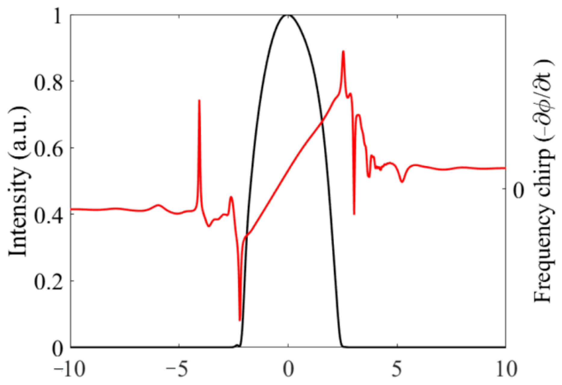
Third, for the transform-limited pulse, the product of spectrum bandwidth and pulse duration is a fixed value. For a Gaussian pulse, the value is 0.441, and for a hyperbolic secant pulse, the value is 0.315. In Figure 3, with the increase in SMF1 (SMF3) dispersion, the spectral bandwidth decreases, and the dechirped pulse duration increases slightly. When the dispersion is set to be 0.0404 ps2/m, the product is 0.729. In addition, when the dispersion is 0.202 ps2/km, the product is 0.605. Both of them indicate that the dechirped pulse is not transform-limited, which can be attributed to the fact that the pule chirp is not linear. Figure 7 gives the chirp () of the pulse when the dispersion is set to 0.0404 ps2/m. The fiber dispersion is normal and the chirp is negative at the leading edge [27]. As seen in Figure 6, the chirp along the edges of the pulse is no longer linear.
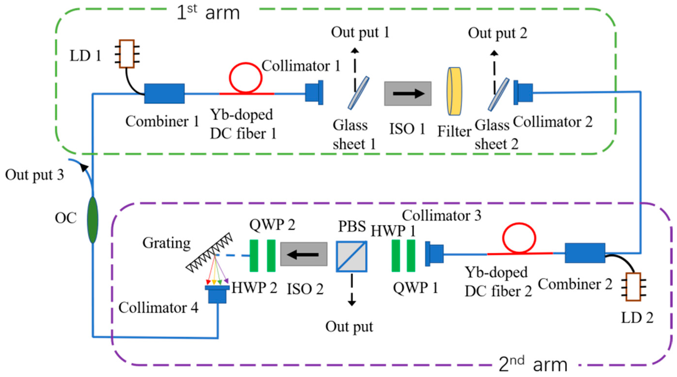
4. Experimental Results
The experimental setup of the Mamyshev oscillator is schematically illustrated in Figure 8. The oscillator consists of two arms. Each arm composes of a segment of Yb-doped double-cladding fiber (Yb-doped DC fiber 1, Yb-doped DC fiber 2) and a 976-nm laser diode (LD 1, LD 2), serving as the pump laser. The pump light is coupled into the gain fiber through two combiners (Combiner 1 and Combiner 2). Two free-space isolators (ISO 1, ISO 2) ensure unidirectional laser operation. A fixed filter (Filter) with a central wavelength of 1061.12 nm and a bandwidth of 4.35 nm is inserted in arm 1. In arm 2, a 600 lines/mm grating, together with two collimators, serves as a tunable filter. To start the Mamyshev oscillator, two quarter-wave plates (QWP 1, QWP 2), one half-wave plate (HWP), and a polarization beam splitter (PBS) are added in arm 2, serving as a nonlinear polarization rotation-based artificial saturable absorber [17,22]. Before the grating, the HWP 2 is used to optimize the diffraction grating efficiency. The reflective port of PBS serves as the main output port of the laser. Other elements include two samplers (Glass sheet 1 and Glass sheet 2) and a 90/10 output coupler (OC) to monitor the spectra at different locations of the cavity. The total cavity length is about 13.8 m, and all the fiber GVD around 1060 nm is normal. The output pulse characteristics are measured by an optical spectrum analyzer (Yokogawa, Musashino, Japan, AQ6374), an autocorrelator (Femtochrome, Berkeley, CA, USA, FR-103XL), an oscilloscope (Gwinstek, New Taipei, Taiwan, gds-2202E), and a radio frequency analyzer (Keysight, Santa Rosa, CA, USA, N9000B).
In the experiment, the central wavelength of the tunable filter in arm 2 is set to be 1064.80 nm firstly, partially overlapping with the fixed filter in arm1 to initiate lasing and pulse formation. Once the laser is mode-locked by adjusting the waveplates, the laser is initially self-started, and the separation between these two filters can be tuned to optimize the oscillator state without losing mode-locking. In the experiment, the adjustable filter in arm 2 was finally fixed at 1067.35 nm. As the filters are apart, the oscillator is no longer self-starting.
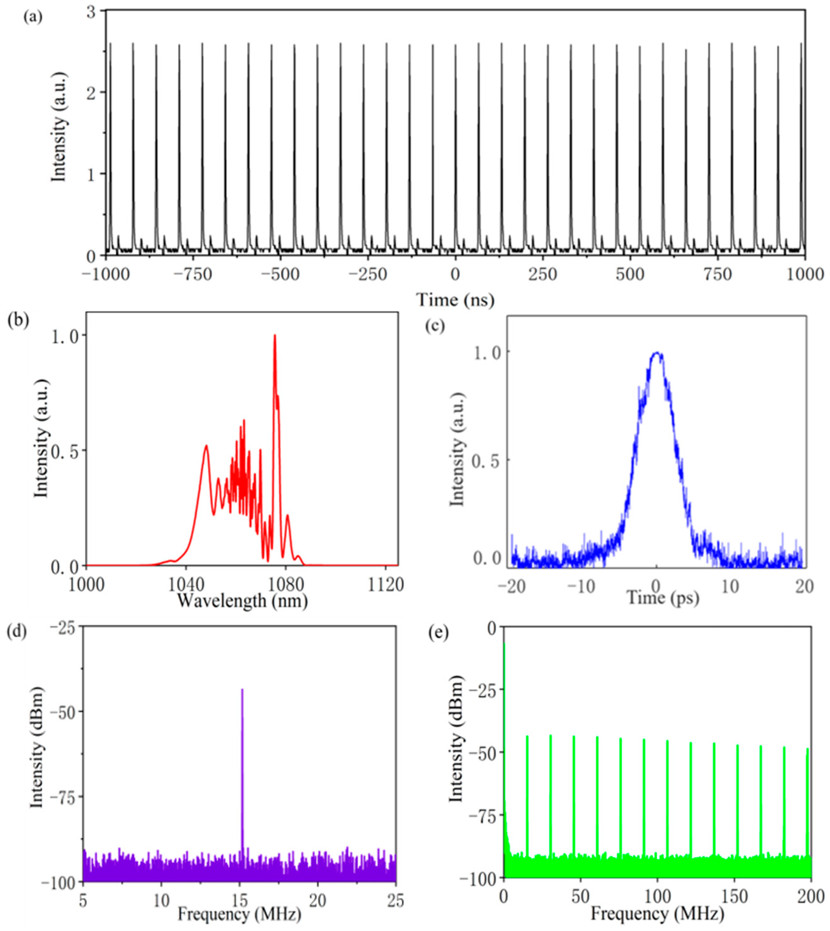
Figure 9 shows the output characteristics of the laser pulse when the pump power of LD 1 and LD 2 are set to be 1.83 W and 3.00 W, respectively. The pulse train, as presented in Figure 9a, has a fundamental repetition rate of 15.18 MHz. Figure 9b gives the spectrum measured at the main output port. The central wavelength is 1062.53 nm, and the 3 dB bandwidth is 29.81 nm. Based on the measured autocorrelation trace depicted in Figure 9c, the pulse width is estimated to be 4.16 ps. The average output power is 130 mW and the corresponding pulse energy is 8.6 nJ. We also measured the radio frequency (RF) spectrum of the pulse train. The RF spectrum around the fundamental repetition rate is illustrated in Figure 9d. The frequency range is 20 MHz and the resolution is set to be 10 Hz. The RF spectrum peak have a high signal-to-noise ratio of ~47 dB. Figure 9e shows the RF spectrum with a frequency range and resolution of 300 MHz and 100 Hz, respectively.
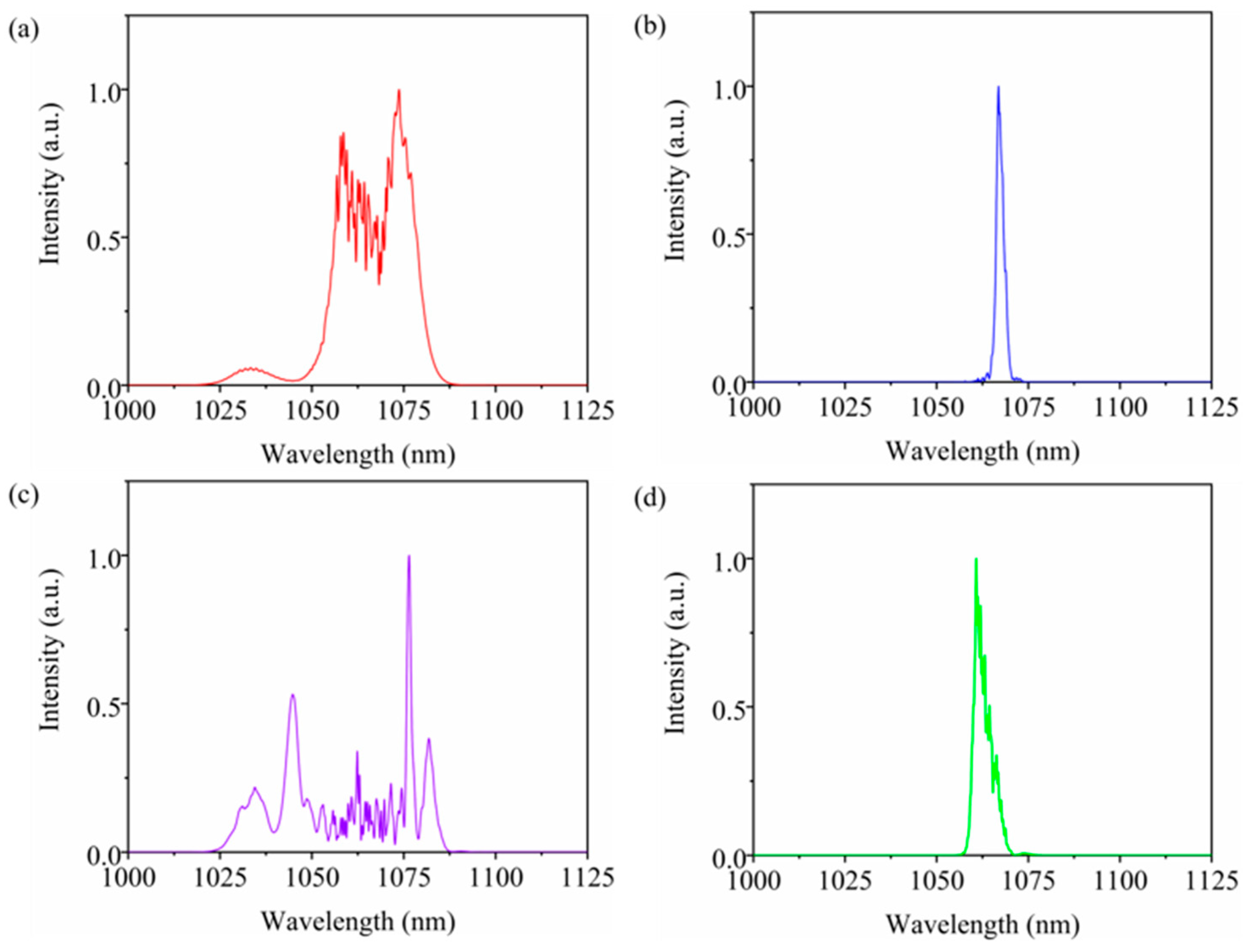
Figure 10 illustrates the spectra at different locations of the cavity. The pump power of LD 1 and LD 2 are 2.15 W and 3.34 W, respectively. Figure 10a gives the spectrum after the collimator in arm 1 (Output 1). The central wavelength is 1067.07 nm and the 3-dB bandwidth is 22.08 nm. After the fixed filter in arm 1, the spectrum is obviously narrowed (Figure 10b). The central wavelength is 1061.65 nm, and the 3-dB bandwidth is 3.31 nm. The filtered spectrum is amplified and broadened as it propagates in the subsequent gain fiber and passive fiber in arm 2. The output spectrum measured on the PBS reflection port is shown in Figure 10c, with a central wavelength of 1060.67 nm and a 3-dB bandwidth of 32.68 nm. Subsequently, the pulse is filtered by the tunable filter composed of diffraction grating and collimators. As shown in Figure 10d, the central wavelength is 1067.24 nm, and the bandwidth is 2.09 nm.
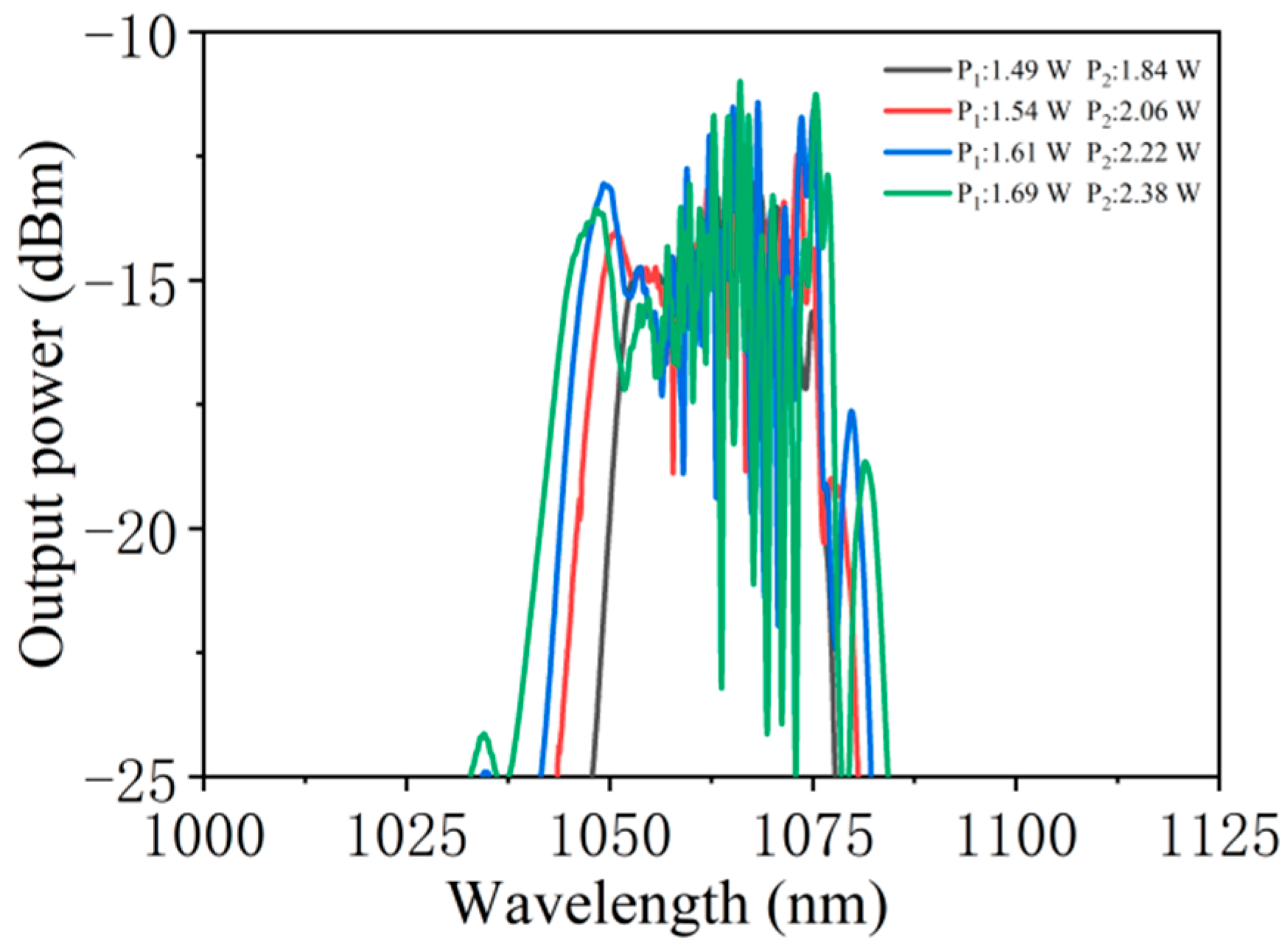
In the simulation, we discuss the dependence of pulse characteristics on cavity parameters, such as fiber dispersion, nonlinearity, small-signal gain coefficient, and filter bandwidth. Independent control of these parameters of the laser is generally challenging. With the given experimental setup, the only parameter that can be altered continuously without seriously affecting other parameters is the small-signal gain coefficient, which can be adjusted by altering the pump power. Figure 11 gives the evolution of the spectra measured from the main output port with the increase in the pump power. P1 and P2 denote the pump power of LD 1 and LD 2, respectively. All the other parameters remain unchanged. The spectral bandwidth increases with the increase in the pump power. With the increase in pump power, the spectral 3-dB bandwidth gradually increases from 21.72 nm to 29.81 nm.
It is worth noting that the dependence of the output pulse characteristics of the Mamyshev fiber oscillator on cavity parameters is mainly investigated here. The experimental results are presented to confirm the simulation results. Independent control of the fiber dispersion, fiber nonlinearity, or filter bandwidth is generally challenging in the experiment. Thus, only the evolution of the spectra with the increase in the pump power has been investigated in the experiment. When the pump power of LD 1 and LD 2 increases from 1.49 W and 1.84 W to 1.69 W and 2.38 W, the spectral 3 dB bandwidth gradually increases from 21.72 nm to 29.81 nm, respectively. The same trend is obtained in the simulation, where the spectral bandwidth increase with the increase in the small-signal gain coefficient. Experimental results agree well with the simulation results, indicating the credibility of the simulation results.
As mentioned above, the dependence of pulse characteristics on the Mamyshev oscillator parameters is discussed in detail. The results would provide a guideline for the design of the ultrashort pulse source on demand. For example, a wide spectrum could be obtained by increasing the nonlinearity of the passive fiber after the gain fiber, while the change in nonlinearity of the passive fiber before the gain fiber has a weak effect on spectrum broadening. Another example comes from the pulse chirp. According to the simulation results, the pulse chirp decreases with the increase in the small-signal gain coefficient, resulting in the decrease in negative dispersion. This, thus, requires pulse to be dechirped. If a pair of gratings is used in the experiment to dechirp the pulse, the needed distance between the two gratings decreases with the increase in pump power. The simulation results provide a road map to optimize the design of a Mamyshev oscillator.
5. Conclusions
A numerical model of a Mamyshev fiber oscillator is presented based on the Ginzburg–Landau equation. The dependence of output pulse characteristics on fiber dispersion, nonlinearity, small-signal gain coefficient of the gain fiber, and filter bandwidth is investigated systematically. Simulation results show that the passive fiber after gain fiber has a stronger influence on spectrum broadening than the passive fiber after the gain fiber. The increase in fiber nonlinearity or reduction in fiber dispersion result in a wide spectral bandwidth and a small chirp. The two filters are key components of the oscillator. The effect of filters bandwidth and the central wavelength interval between them is discussed. Simulation results show that pulse width increases with the increase in filter bandwidth. Finally, a Mamyshev fiber oscillator is established with Yb-doped fiber to confirm the credibility of simulation results. An average power of 130 mW is obtained, with a pulse energy of 8.6 nJ. The pulse duration is measured to be 4.16 ps. The output pulse property is discussed with the increase in the pump power, which shows good agreement with the simulation results. The use of discrete elements makes the oscillator complicated. A more compact structure could be constructed with all-fiber components. The Mamyshev oscillator is a potential robust laser source for delivering high-energy pulse, with significant tunability of the pulse spectrum bandwidth, pulse duration, and chirp. Our results provide a guideline for the design of an ultrashort pulse source on demand as well as a road map to optimize the design of a Mamyshev oscillator.
Author Contributions
Conceptualization, N.-K.C., X.Z. and L.Z.; Methodology, Z.T., and H.H.; software, L.Z. and Y.Y.; validation, Y.X., and X.Z.; formal analysis, H.H. and Y.H.; investigation, H.H., Y.Y. and L.Z.; resources, Y.Y., and Y.X.; data curation, Y.H.; writing—original draft preparation, H.H. and L.Z.; writing—review and editing, N.-K.C. and Z.T.; visualization, Y.H.; project administration, N.-K.C.; funding acquisition, N.-K.C., L.Z., Y.X. and Y.Y. All authors have read and agreed to the published version of the manuscript.
Funding
This work was supported in part by the National Natural Science Foundation of China under Grants 61875247, by Natural Science Foundation of Shandong Province under Grants ZR2020QA068 and ZR2020QF086, and by Liaocheng University under Grants 318012023, 318051412, 31805180101, and 319190301.
Institutional Review Board Statement
Not applicable.
Informed Consent Statement
Not applicable.
Data Availability Statement
Data available on request.
Acknowledgments
Liqiang Zhang acknowledge the support of Introduction and Cultivation Plan of Youth Innovation Talents for Universities of Shandong Province, China.
Conflicts of Interest
The authors declare no conflict of interest.
References
- Fu, W.; Wright, L.G.; Sidorenko, P.; Backus, S.; Wise, F.W. Several new directions for ultrafast fiber lasers. Opt. Express 2018, 26, 9432–9463. [Google Scholar] [CrossRef]
- Mollenauer, L.F.; Stolen, R.H.; Gordon, J.P. Experimental observation of picosecond pulse narrowing and solitons in optical fibers. Phys. Rev. Lett. 1980, 45, 1095. [Google Scholar] [CrossRef]
- Tamura, K.; Ippen, E.P.; Haus, H.A.; Nelson, L.E. 77-fs pulse generation from a stretched-pulse mode-locked all-fiber ring laser. Opt. Lett. 1993, 18, 1080–1082. [Google Scholar] [CrossRef] [PubMed]
- Anderson, D.; Desaix, M.; Karlsson, M.; Lisak, M.; Quiroga-Teixeiro, M.L. Wave-breaking-free pulses in nonlinear-optical fibers. J. Opt. Soc. Am. B 1993, 10, 1185. [Google Scholar] [CrossRef]
- Ilday, F.Ö.; Buckley, J.R.; Clark, W.G.; Wise, F.W. Self-similar pulse evolution of parabolic pulses in a laser. Phys. Rev. Lett. 2004, 92, 213902. [Google Scholar] [CrossRef] [Green Version]
- Chong, A.; Renninger, W.H.; Wise, F.W. All-normal-dispersion femtosecond fiber laser with pulse energy above 20 nJ. Opt. Lett. 2007, 32, 10095–10100. [Google Scholar] [CrossRef]
- Saraceno, C.J.; Schriber, C.; Mangold, M.; Hoffmann, M.; Heckl, O.H.; Baer, C.R.E.; Golling, M.; Südmeyer, T.; Keller, U. SESAMs for high-power oscillators: Design guidelines and damage thresholds. IEEE J. Sel. Top. Quantum Electron. 2012, 18, 29–41. [Google Scholar] [CrossRef]
- Stolen, R.H.; Botineau, J.; Ashkin, A. Intensity discrimination of optical pulses with birefringent fibers. Opt. Lett. 1982, 7, 512–514. [Google Scholar] [CrossRef]
- Duling, I.N. All-fiber ring soliton laser mode locked with a nonlinear mirror. Opt. Lett. 1991, 16, 539–541. [Google Scholar] [CrossRef] [PubMed]
- Rochette, M.; Chen, L.R.; Sun, K.; Hermandez-Cordero, J. Multiwavelength and tunable self-pulsating fiber cavity based on regenerative SPM spectral broadening and filtering. IEEE Photonics Technol. Lett. 2008, 20, 1497–1499. [Google Scholar] [CrossRef]
- Regelskis, K.; Ždludevičius, J.; Viskontas, K.; Račiukaitis, G. Ytterbium-doped fiber ultrashort pulse generator based on self-phase modulation and alternating spectral filtering. Opt. Lett. 2015, 40, 5255–5258. [Google Scholar] [CrossRef] [PubMed]
- Fu, W.; Wright, L.G.; Wise, F.W. High-power femtosecond pulses without a modelocked laser. Optica 2017, 4, 831–834. [Google Scholar] [CrossRef]
- Piche, M. Mode locking through nonlinear frequency broadening and spectral filtering. Proc. SPIE 1994, 2041, 358–365. [Google Scholar] [CrossRef]
- Liu, Z.; Ziegler, Z.M.; Wright, L.G.; Wise, F.W. Megawatt peak power from a Mamyshev oscillator. Optica 2017, 4, 649–654. [Google Scholar] [CrossRef] [PubMed]
- Sidorenko, P.; Fu, W.; Wright, L.G.; Olivier, M.; Wise, F.W. Self-seeded, multi-megawatt, Mamyshev oscillator. Opt. Lett. 2018, 43, 2672–2675. [Google Scholar] [CrossRef] [PubMed]
- Wang, P.; Yao, S.; Grelu, P.; Xiao, X.; Yang, C. Pattern formation in 2-μm Tm Mamyshev oscillator associated with the dissipative Faraday instability. Photonics Res. 2019, 7, 1287–1295. [Google Scholar] [CrossRef]
- Ma, C.; Khanolkar, A.; Zang, Y.; Chong, A. Ultrabroadband, few-cycle pulses directly from a Mamyshev fiber oscillator. Photonics Res. 2020, 8, 65–69. [Google Scholar] [CrossRef]
- Wang, T.; Ren, B.; Li, C.; Wu, J.; Ma, R.; Su, P.; Luo, Z.C.; Zhou, P. Over 80 nJ sub-100 fs all-fiber Mamyshev oscillator. IEEE J. Sel. Top. Quant. Electron. 2021, 27, 8800105. [Google Scholar] [CrossRef]
- Liu, W.; Liao, R.; Zhao, J.; Cui, J.; Song, Y.; Wang, C.; Hu, M. Femtosecond Mamyshev oscillaor with 10-MW-level peak power. Optica 2019, 6, 194–197. [Google Scholar] [CrossRef]
- Luo, X.; Tuan, T.H.; Saini, T.S.; Nguyen, H.P.T.; Suzuki, T.; Ohishi, Y. All-fiber mode-locked laser based on Mamyshev mechanism with high-energy pulse generation at 1550 nm. J. Lightwave Technol. 2020, 38, 1468–1473. [Google Scholar] [CrossRef]
- Poeydebat, E.; Scol, F.; Vanvincq, O.; Bouwmans, G.; Hugonnot, E. All-fiber Mamyshev oscillator with high average power and harmonic mode-locking. Opt. Lett. 2020, 45, 1395–1398. [Google Scholar] [CrossRef] [PubMed]
- Chen, Y.H.; Sidorenko, P.; Thorne, R.; Wise, F. Starting dynamics of a linear-cavity femtosecond Mamyshev oscillator. J. Opt. Soc. Am. B 2021, 38, 743–748. [Google Scholar] [CrossRef] [PubMed]
- Närhi, M.; Fedotov, A.; Aksenova, K.; Fiebrandt, J.; Schönau, T.; Gerecke, M.; Gumenyuk, R. Design guidelines for ultrashort pulse generation by a Mamyshev regenerator. Opt. Express 2021, 29, 15699–15710. [Google Scholar] [CrossRef] [PubMed]
- Chong, A.; Renninger, W.H.; Wise, F.W. Properties of normal-dispersion femtosecond fiber laser. J. Opt. Soc. Am. B 2008, 25, 140–148. [Google Scholar] [CrossRef]
- Chong, A.; Liu, H.; Nie, B.; Bale, B.G.; Wabnitz, S.; Renninger, W.H.; Dantus, M.; Wise, F.W. Pulse generation without gain-bandwidth limitation in a laser with self-similar evolution. Opt. Express 2012, 20, 14213–14220. [Google Scholar] [CrossRef] [Green Version]
- Haig, H.; Sidorenko, P.; Thorne, R.; Wise, F.W. Generation of 70-nJ and 40-fs pulses by a ring Mamyshev oscillator with a single gain segment. In Proceedings of the Conference on Lasers and Electro-Optics, San Jose, CA, USA, 9–14 May 2021. [Google Scholar]
- Agrawal, G.P. Nonlinear Fiber Optics, 5th ed.; Elsevier/Academic Press: London, UK, 2013. [Google Scholar]
Figure 1.
Numerical model of the Mamyshev oscillator and spectra at different locations of the cavity.
Figure 1.
Numerical model of the Mamyshev oscillator and spectra at different locations of the cavity.

Figure 2.
Evolution of spectrum bandwidth and pulse duration in the cavity.

Figure 3.
Dependence of pulse characteristics on fiber group velocity dispersion.

Figure 4.
Dependence of pulse characteristics on the fiber nonlinear coefficient.

Figure 5.
Dependence of pulse characteristics on the small-signal gain coefficient of the gain fiber.
Figure 5.
Dependence of pulse characteristics on the small-signal gain coefficient of the gain fiber.

Figure 6.
Dependence of pulse characteristics on filter bandwidth.

Figure 7.
The chirp along the edges of the pulse.

Figure 8.
Schematic of the Mamyshev fiber oscillator.

Figure 9.
Output characteristics of the pulse. (a) pulse train, (b) spectrum; (c) Autocorrelation trace, (d) radio frequency spectrum in a range of 20 MHz; (e) radio frequency spectrum in a range of 300 MHz.
Figure 9.
Output characteristics of the pulse. (a) pulse train, (b) spectrum; (c) Autocorrelation trace, (d) radio frequency spectrum in a range of 20 MHz; (e) radio frequency spectrum in a range of 300 MHz.

Figure 10.
(a–d) Spectra at different locations of the oscillator.

Figure 11.
Output spectra under different pump powers.

Publisher’s Note: MDPI stays neutral with regard to jurisdictional claims in published maps and institutional affiliations. |
© 2021 by the authors. Licensee MDPI, Basel, Switzerland. This article is an open access article distributed under the terms and conditions of the Creative Commons Attribution (CC BY) license (https://creativecommons.org/licenses/by/4.0/).
Share and Cite
MDPI and ACS Style
Han, H.; Chen, N.-K.; Zhang, L.; Xie, Y.; Tian, Z.; Yao, Y.; Huang, Y.; Zhang, X. Output Pulse Characteristics of a Mamyshev Fiber Oscillator. Photonics 2021, 8, 590. https://doi.org/10.3390/photonics8120590
AMA Style
Han H, Chen N-K, Zhang L, Xie Y, Tian Z, Yao Y, Huang Y, Zhang X. Output Pulse Characteristics of a Mamyshev Fiber Oscillator. Photonics. 2021; 8(12):590. https://doi.org/10.3390/photonics8120590
Chicago/Turabian StyleHan, Haili, Nan-Kuang Chen, Liqiang Zhang, Yanru Xie, Zhen Tian, Yicun Yao, Yuanchuan Huang, and Xia Zhang. 2021. "Output Pulse Characteristics of a Mamyshev Fiber Oscillator" Photonics 8, no. 12: 590. https://doi.org/10.3390/photonics8120590
Note that from the first issue of 2016, this journal uses article numbers instead of page numbers. See further details here.