1. Introduction
Three-dimensional (3D) display technology using diffractive optical elements (DOEs) and computer-generated holograms (CGHs) is increasingly being used in AR/VR entertainment, surgical procedures, and the military [
1]. In reconstructing a scene of a 3D image, depth information is encoded in the form of CGHs via numerical computation. The resulting numerical CGHs can be physically manufactured or displayed in a spatial light modulator (SLM) by displaying a grayscale version of the CGH phase. The physical CGH in a diffractive optical system modulates an incident optical beam to reconstruct the encoded 3D images via free-space propagation. Holographic reconstructions of 3D images in space using a CGH or a series of CGHs provide abundant depth cues of scenes and objects. High light usage efficiency, high image resolution, and high spatial precision make holographic 3D display technology an ideal candidate for additive manufacturing (i.e., 3D printing).
Through the successive layering of materials, additive manufacturing (AM) makes it possible to fabricate bespoke 3D objects [
2,
3,
4,
5], ranging in size from small toys and teeth to large objects, including houses and cars. AM technology is ideally suited to the creation of early prototypes and highly specialized items in low volumes for which tooling costs would be untenable. Three-dimensional photocuring is one approach to AM manufacturing in which UV/Vis light is used to polymerize photosensitive resin via layer-by-layer patterning for the fabrication of small elaborate objects. Point-by-point and layer-by-layer patterning are the two main approaches to photocuring, due to their ease of implementation and low cost. Unfortunately, these methods tend to be slow and are susceptible to the formation of layering artifacts, which can affect surface quality.
In this study, we developed a layer-based 3DHD method to facilitate 3D printing through the photopolymerization of photocurable acrylate resin. Briefly, a compound CGH is displayed in a liquid-crystal-on-silicon spatial light modulator (LCoS-SLM) as an input device in a diffractive optical system generating a layered 3D image in the optical near field of scalar diffraction. As photocurable resin is gradually introduced, a photopolymeric 3D object is formed. The proposed method features high light efficiency, high image resolution, rapid fabrication, and good object continuity.
Section 2 presents a brief review of current AM techniques and four approaches to holographic 3D display systems.
Section 3 illustrates the fundamental diffraction theory employed in this study and the algorithms used for the optimization of CGH.
Section 4 outlines the implementation of the proposed holographic 3D printing apparatus and photopolymerized objects.
Section 5 includes a discussion of the current study with an overview of the merits, limitations, and future challenges in the ongoing development of this technology.
2. Literature Review
2.1. Current Additive Manufacturing Technology
Three-dimensional photocuring in AM involves the use of UV/V is light to polymerize photosensitive resin via layer-by-layer patterning. Current photocuring patterning methods are classified as one-dimensional (1D) or two-dimensional (2D).
Conventional 1D (i.e., point-by-point) patterning is a stereolithographic (SLA) process, in which a laser beam is moved across the surface of photosensitive resin to form a 2D layer from the bottom up [
6,
7]. SLA is considered a mature technology widely used in many fields. Recent advances in 1D patterning employ direct laser writing [
8] and single-mode fibers [
9] to achieve sub-micro resolution.
Two-dimensional patterning, also known as digital light processing (DLP), involves the projection of a 2D target pattern on the surface of photosensitive resin to initiate polymerization. These systems comprise an image display panel, an optical imaging setup, and a mechanism stage to move the patterned object in the axial direction [
10,
11,
12,
13,
14]. The pattern is then moved upward or downward as the patterning process proceeds. The DLP approach is easily implemented using inexpensive commercial digital micromirror devices (DMD) and light-emitting diodes (LED) [
10,
11,
12]. The discontinuity problem of DLP has largely been resolved by inserting a continuous liquid interface (CLIP) [
13] and altering the projection orientation (CAL) [
14].
Coherent optical light sources provide excellent directional propagation and intensity reformation, which can be used to generate 3D intensity distributions with high light diffraction efficiency in space. The first use of holographic processing for 3D printing involved the fabrication of complex polymer structures via one-step volumetric AM [
15]. A CGH displayed in a phase-mode SLM was used to produce three holographic patterns simultaneously, which were then directed to form a 3D intensity distribution suitable for photopolymerization.
2.2. Holographic 3D Display Methods
Holographic 3D display (3DHD) technology is highly efficient in terms of light usage in forming high-resolution holographic images of high precision. In the following, we examine 3DHD techniques, which can be classified as point-based, layer-based, polygon-based, and 3D beam shaping.
The point-based approach involves pre-calculating quadratic phases characterized by the wavelength and the focus distances of optical spots, which are then stored in a lookup table (LUT) [
16,
17]. A CGH is assembled using the quadratic phases corresponding to optical spots in a 3D image. The layered-based approach involves slicing a 3D image into a series of 2D images, the CGHs/DOEs of which are calculated using an optimization algorithm, such as the Gerchberg–Saxton algorithm [
18,
19,
20,
21]. The CGHs of the 2D image are then combined by adding in the complex-amplitude manner or being displayed in a temporal sequence to form a 3D image. In the polygon-based approach [
22,
23], the surface of a 3D object is represented by a set of polygons from which CGHs are calculated and combined. In the 3D beam-shaping approach, 3D patterns can be approximated from their 2D complexed-amplitude function; therefore, 3D images are created from the corresponding CGHs [
24]. The CGHs obtained using the above approaches reconstruct the optical 3D intensity distribution with which an optical Fourier transform system is equipped [
25].
2.3. Summary
Three-dimensional photocuring using point-by-point [
6,
7,
8,
9] and layer-by-layer [
10,
11,
12,
13] patterning methods are well-suited to the manufacture of small 3D objects, such as toys and teeth; however, the build rate is slow and the surface quality is less than ideal. The reforming of incident light into an optical intensity distribution is one potential approach to resolving these problems [
14,
15]. Holographic 3D display technology using CGHs is well-suited to manipulating the 3D distribution of optical waves [
16,
17,
18,
19,
20,
21,
22,
23,
24,
25].
3. Methods
3.1. Near-field Diffraction Using Angular Spectrum Method
The angular spectrum method (ASM) is used to calculate the complex amplitude distribution of an optical field when the source is monochromatic and coherent [
25]. Unlike approximations to the amplitude distribution using the Fresnel diffraction formula, the ASM provides a precise result to the complex amplitude distribution of diffraction in the optical near field. When using the ASM, the physical extent of the diffraction distribution is identical to that of the incident distribution, regardless of the propagation distance, thereby enabling the calculation of diffraction distribution with a high degree of detail.
When using the ASM, the complex amplitude distribution of an optical field in a specified plane (e.g.,
z) is decomposed into a linear combination of plane waves travelling in different directions away from that plane. The decomposition of an arbitrary optical field into plane waves is conducted using the 2D Fourier transform, as follows:
where
A(
fx,
fy;
z) denotes the complex-valued amplitude of the 2D sinusoidal plane wave of frequency pair (
fx,
fy) on the
z plane. In Equation (1),
U(
x,
y,
z) is seen as a 2D function as an optical travelling field intercepted in the
z plane; therefore, the frequency component
A(
fx,
fy;
z) can be identified as 3D plane waves of wavelength
λ travelling in specific directions and intercepted in that plane. The 2D sinusoidal function of frequencies (
fx,
fy) is regarded as the propagation of 3D plane waves in space with wave vector
of magnitude 2π/
λ and direction cosines (
α,
β,
γ) identified as follows:
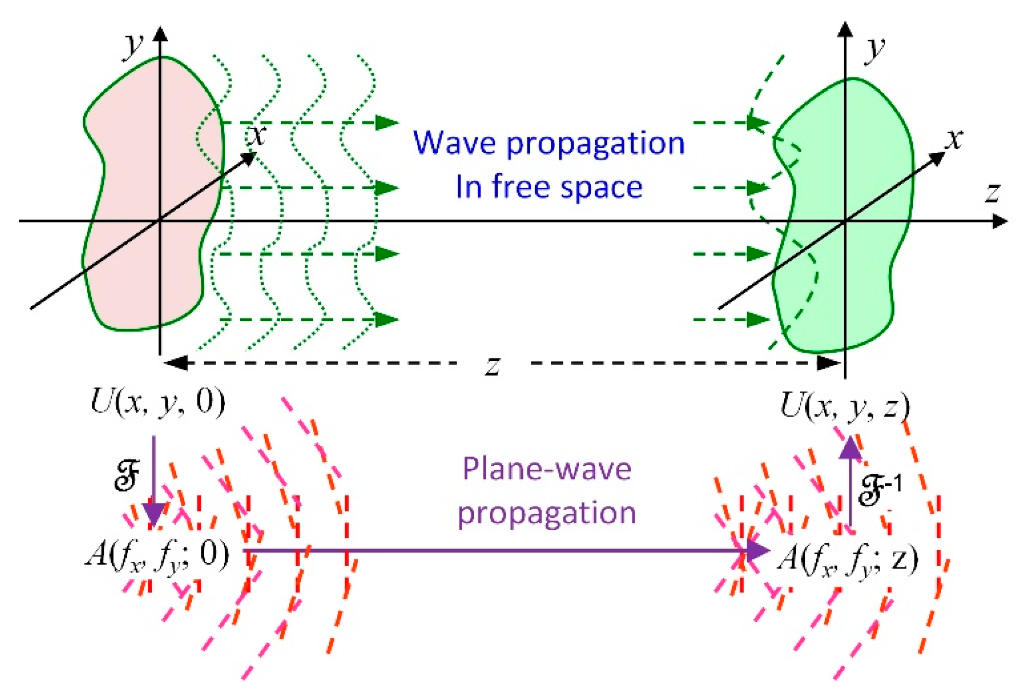
Figure 1 presents a geometrical schematic showing an optical wave travelling through space, where the given complex amplitude function crosses the plane of
z = 0 and the diffraction amplitude function crosses plane at a distance
z, denoted as
U(
x,
y, 0) and
U(
x,
y,
z), respectively. Using Equations (1) and (2), the angular spectra of the two fields can be expressed as follows:
where
denotes a 2D Fourier transform operation. The inverse 2D Fourier transform is denoted by
. The plane wave of direction cosines (
α,
β,
γ) propagates across two planes separated by a distance of
z, and is therefore subject to phase delay, as follows:
Finally, the complex amplitude distribution obtained at (
x,
y,
z) can be expressed in terms of the initial angular spectrum using the inverse transform in Equation (4), written as follows:
The complex amplitude distribution of diffraction described above can be expressed using operator notation to simplify calculations. In addition to the Fourier transform and inverse Fourier transform operators defined above,
Q[]{} is used for the multiplication of a quadratic-phase exponential, expressed as follows:
Equations (2), (5) and (6) can then be combined to compute the complex amplitude distribution of diffractive disturbance in an operator-notation form, as follows:
3.2. Iterative Angular Spectrum Algorithm (IASA)
In the current study, computer-generated holograms (CGHs) illuminated by a coherent beam were used to generate holographic images. Function U(x, y, 0) is the resulting complex amplitude distribution when the amplitude function of the incident wavefront is modified by the complex transmittance function of the CGH. When CGHs are implemented with a spatial light modulator (SLM) for holographic displays, the amplitude in U(x, y, 0) has to be a constant value or unity for simplicity (i.e., phase-only CGH). The close approximation of an image function U(x, y, z) with a specified target amplitude from a constant-amplitude U(x, y, 0) requires an optimization algorithm to minimize the noise in U(x, y, z).
Generating the desired image in the optical near field of a CGH requires an inverse calculation (i.e., reversing Equation (7)) as follows:
Note that Equations (7) and (8) remain valid as long as the propagation distance is at least two orders of magnitude higher than the wavelength of interest. When the propagation distance is small, evanescent waves must be taken into account, resulting in exceedingly complex propagation formulas [
26].
Abbreviations, symbols, and notations used in this section are summarized in
Appendix A for readers’ reference.
Our objective in this study was to produce 3D images by simultaneously projecting multiple 2D images from various distances, such that the successive 2D images appear in three dimensions. Each 2D image was produced from a CGH to be used later in comprising a compound CGH to produce a 3D image. We adopted the iterative angular spectrum algorithm (IASA) [
26] to calculate individual CGHs with complex-amplitude
Ui(
x,
y, 0), producing the desired 2D image on the plane at distance
zi (i.e.,
U(
x,
y,
zi)). After we assign a desired target of amplitude
ti(
x,
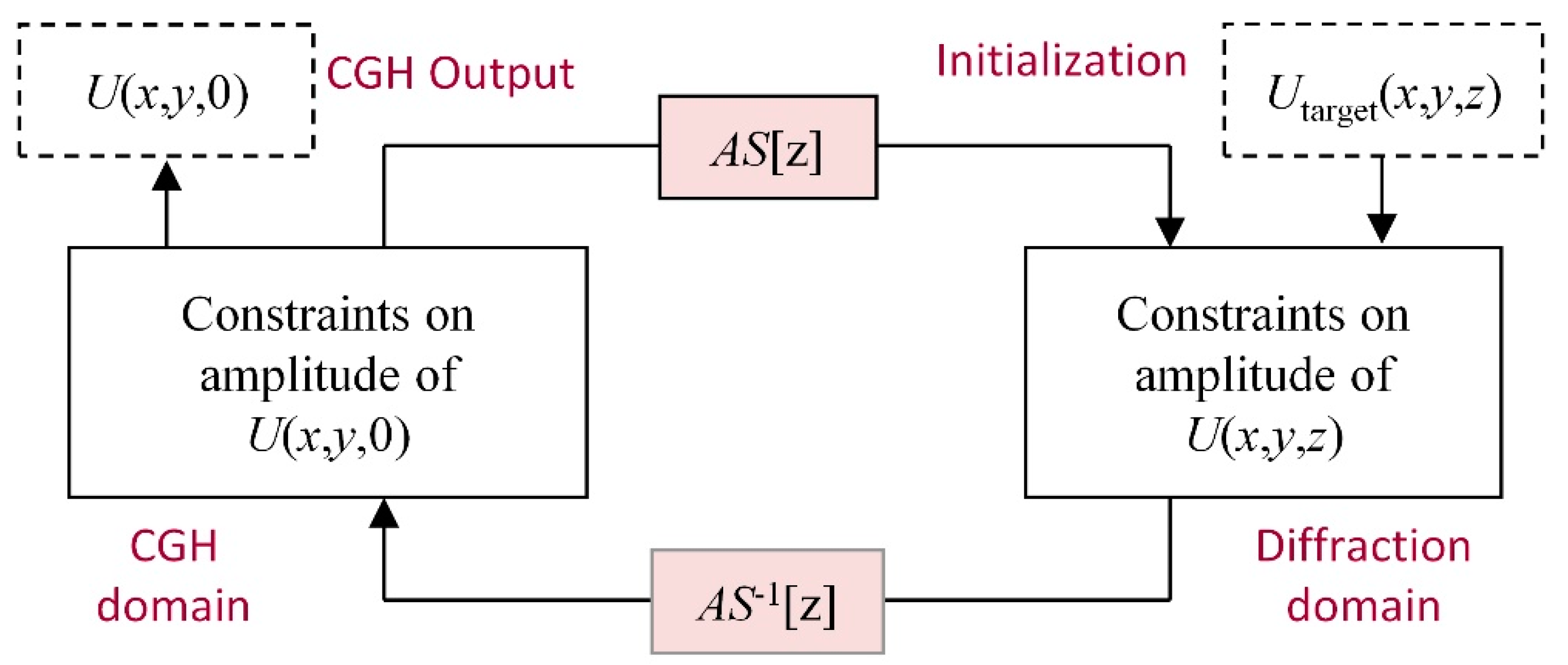
y) and an initial phase selected at random, the IASA implements four iterative operations:
- (1)
Application of inverse propagation (using Equation (8)) to the desired image to obtain an estimate of the CGH;
- (2)
Replacing the amplitude of the computed function with a constant value to obtain an estimate of the phase-only CGH;
- (3)
Application of the forward propagation (using Equation (7)) to the estimated function of the desired image;
- (4)
Replacing the amplitude of the computed image, |U(x, y, z)|, with the target amplitude to approximate the desired image.
Figure 2 presents a flowchart of the IASA implementation, in which the iterative operations were terminated after a defaulted number of iterations were completed. In step (3), we calculated the diffraction efficiency of the estimated image and then took steps to ensure that the final diffraction efficiencies of the CGHs of any 3D image fell within 5% of this value. In instances where the diffraction efficiency of a CGH failed to meet this criterion, another initial phase was used. This process was iterated until all of the CGHs satisfied the requirement of equal diffraction efficiency.
3.3. Generation of Layered 3D Images Using Iterative Angular Spectrum Algorithm (IASA)
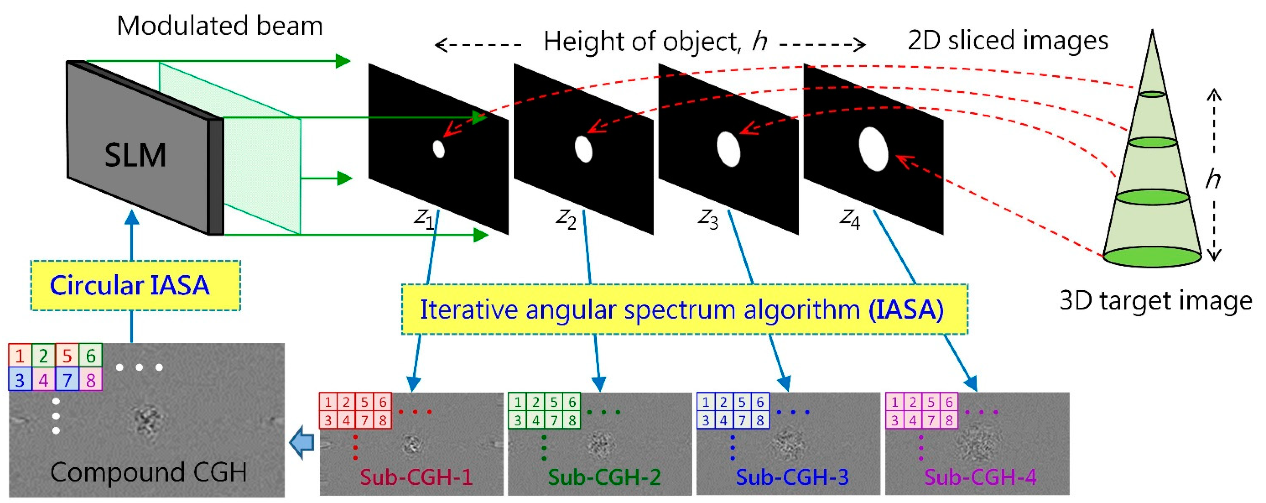
Our objective was to create a layered 3D image comprising multiple successive 2D images using a CGH combining the sub-CGHs of the corresponding 2D images. We first calculated the sub-CGHs of various zi images using an IASA program composed on MATLAB. The sub-CGHs were down-sampled and tiled to form a compound CGH.
We constructed a 3D image of height
h using four 2D images separated at distances of
z1,
z2,
z3, and
z4, where
h =
z4 −
z1. After defining the four 2D target images, we calculated four sub-CGHs using the IASA program. A compound CGH was then created by removing every other pixel from the sub-CGHs beginning at different pixels. As shown in
Figure 3, the phase information of sub-CGH is indicated by different colors (red: 1, green: 2, blue: 3, purple: 4). The index number (1–8) in a CGH indicates the corresponding location of pixels. A compound CGH is constructed by moving pixels 1, 5, … of sub-CGH-1 to pixels 1, 5, … of the compound CGH, and then moving pixels 2, 6, … from sub-CGH-2 to pixels 2, 6, … of the compound CGH, and so on. This means that at any given time, only one quarter of the phase information in the individual sub-CGH is moved to the compound CGH.
The compound CGH was then used to optimize the four 2D images by implementing a circular IASA program to equalize the diffraction efficiency of the four images. Calculations for the circular IASA involve multiple cycles of sequential optimization pertaining to the four 2D images. In each cycle, the compound CGH updates the corresponding phase values based on the optimization of its 2D target image on the zi plane. Upon convergence, other phase values in the compound CGH are updated in accordance with the next 2D target image. All of the phase values of the compound CGH are updated cyclically for the four target images. The process of optimizing the compound CGH proceeds until the requirement of equal diffraction efficiency is achieved. Note that the circular IASA approach improves the quality of the entire 3D image, despite the fact that three quarters of the phase information is discarded in each sub-CGH.
The optimized compound CGH was then uploaded to a phase-mode SLM to create a 3D layered image. Here, we selected
z1 = 125 mm with the operating wavelength
λ = 532 nm and several
h values ranging from 10 to 30 mm.
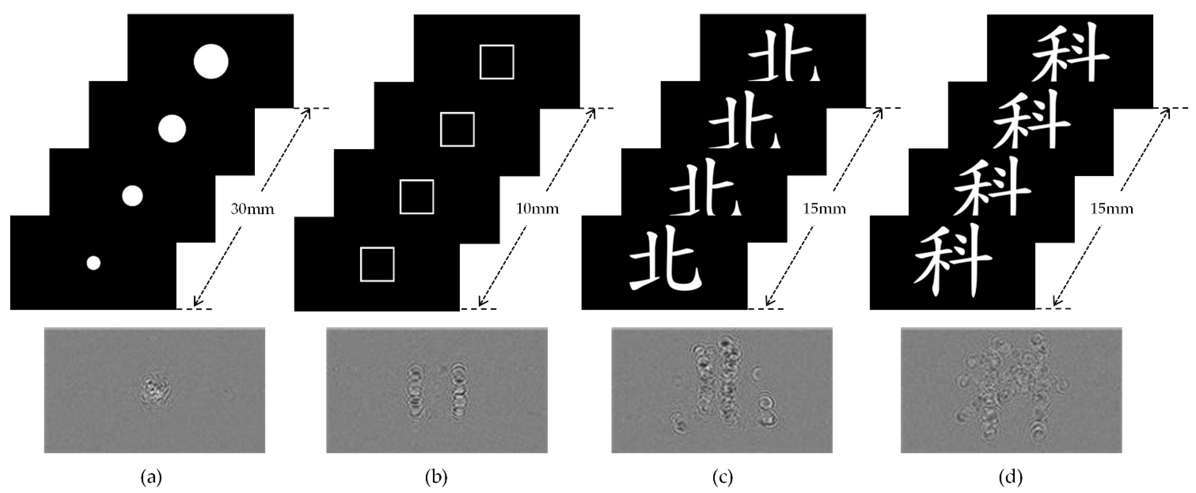
Figure 4 shows four sets of the 2D layered images and the corresponding compound CGHs (1920 × 1080 px; pixel pitch = 6.4 μm; wavelength = 0.532 μm), calculated using the proposed algorithms. When implemented on a desktop computer (i7-8700, 6 cores), the elapsed time per iteration was 3.42 s, and 20 to 30 iterations were required to calculate each sub-CGH. We conducted 7 to 15 cycles of calculations for the processing of 3D images using the circular IASA, the elapsed time of which was 20 to 60 min.
Note that in
Figure 3 and
Figure 4, the CGHs are represented in 8-bit gray scale (0 to 255), the values of which provide the corresponding electrical potentials across the pixels of the SLM with phase differences of 0 to 2π radians.
4. Experiments and Results
We devised a novel apparatus for the proposed near-field diffractive optical printing scheme. A 3D image comprising four 2D images was generated in a 3D space within a glass beaker. The gradual introduction of photopolymeric resin into the beaker meant that no mechanism stage was required to create 3D photopolymerized objects. When the resin reached a specified height (slightly exceeding the depth of the 3D image), the laser was switched off, the beaker was removed, and the object was retrieved.
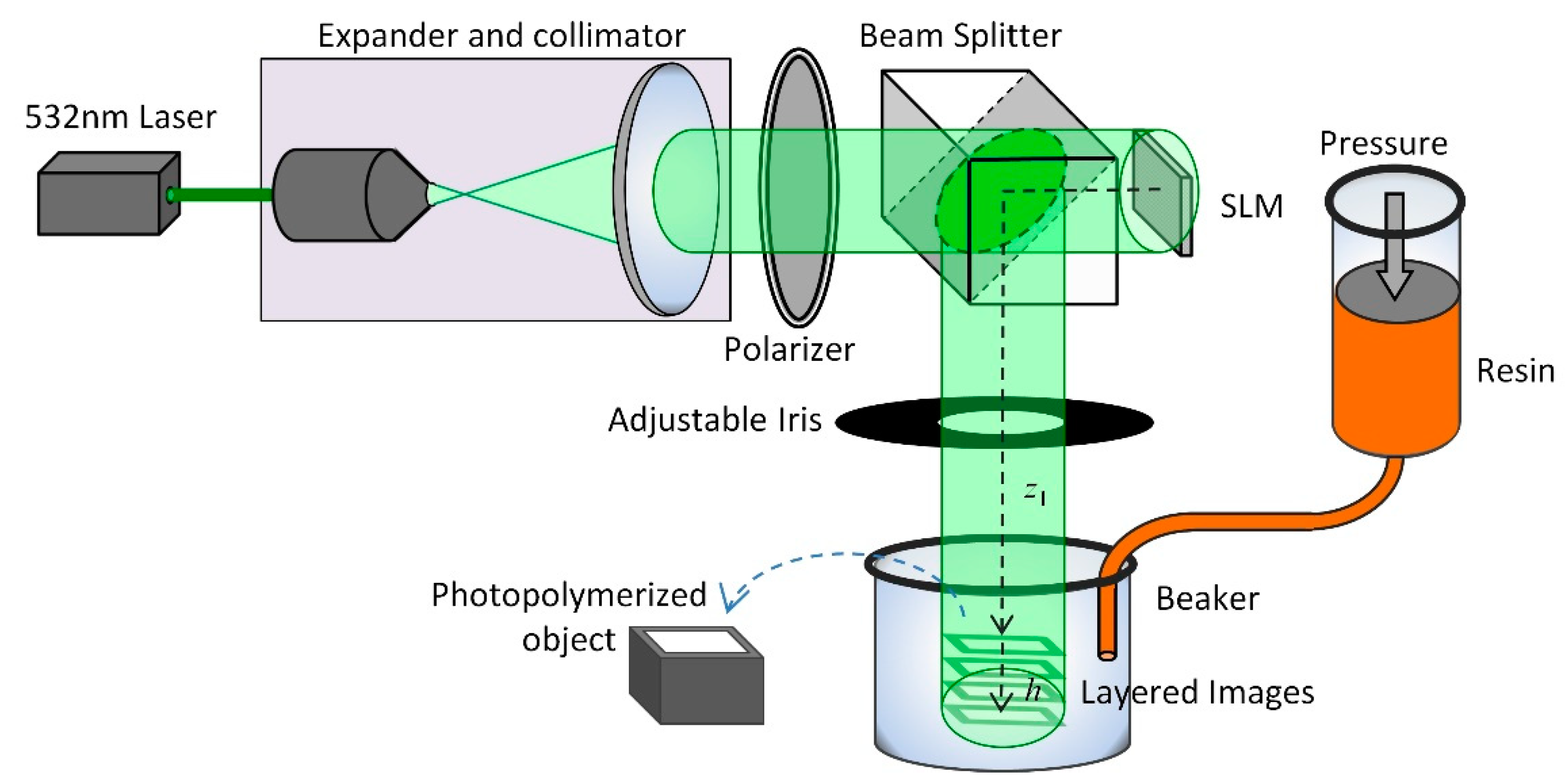
4.1. Near-Field 3D Printing Apparatus
Figure 5 presents the proposed 3DHD printing system, comprising a 532 nm laser source (25 mW), a beam expander and collimator, a polarizer, a beam splitter, an LCoS SLM (JD8554, Jasper Display Corp., Santa Clara, CA), an adjustable iris, a glass beaker, and a resin injector. The laser beam was first expanded and collimated, passed through a polarizer, and then impinged on the LCoS SLM, in which a compound CGH was displayed. Note that the propagation direction of the modulated beam (reflected from the SLM) was shifted by 90° at the beam splitter. An adjustable iris was used to suppress high-order diffraction and allow the 0th order term to arrive at the glass beaker, into which the photopolymer resin was gradually introduced using an injector at a rate of 0.06 mm/s. The 3D layered image was generated in the bottom half of the beaker.
4.2. Experiment Results
When a 3D layered image is generated in space, the intensity distribution appears continuous along the transverse plane, as well as the longitudinal direction, as long as the difference between patterns in the neighboring planes is not large. An acrylate photocurable resin containing HNu 470, 535, and 635 (intended for visible light) was used to initiate photopolymerization of the monomer [
27]. Note that this acrylate resin also contains HNu470 and HNu 635; however, the best photopolymerization performance was obtained when using a wavelength of 532 nm, and the optical power was 170 μW (measured at the location of the 3D image).
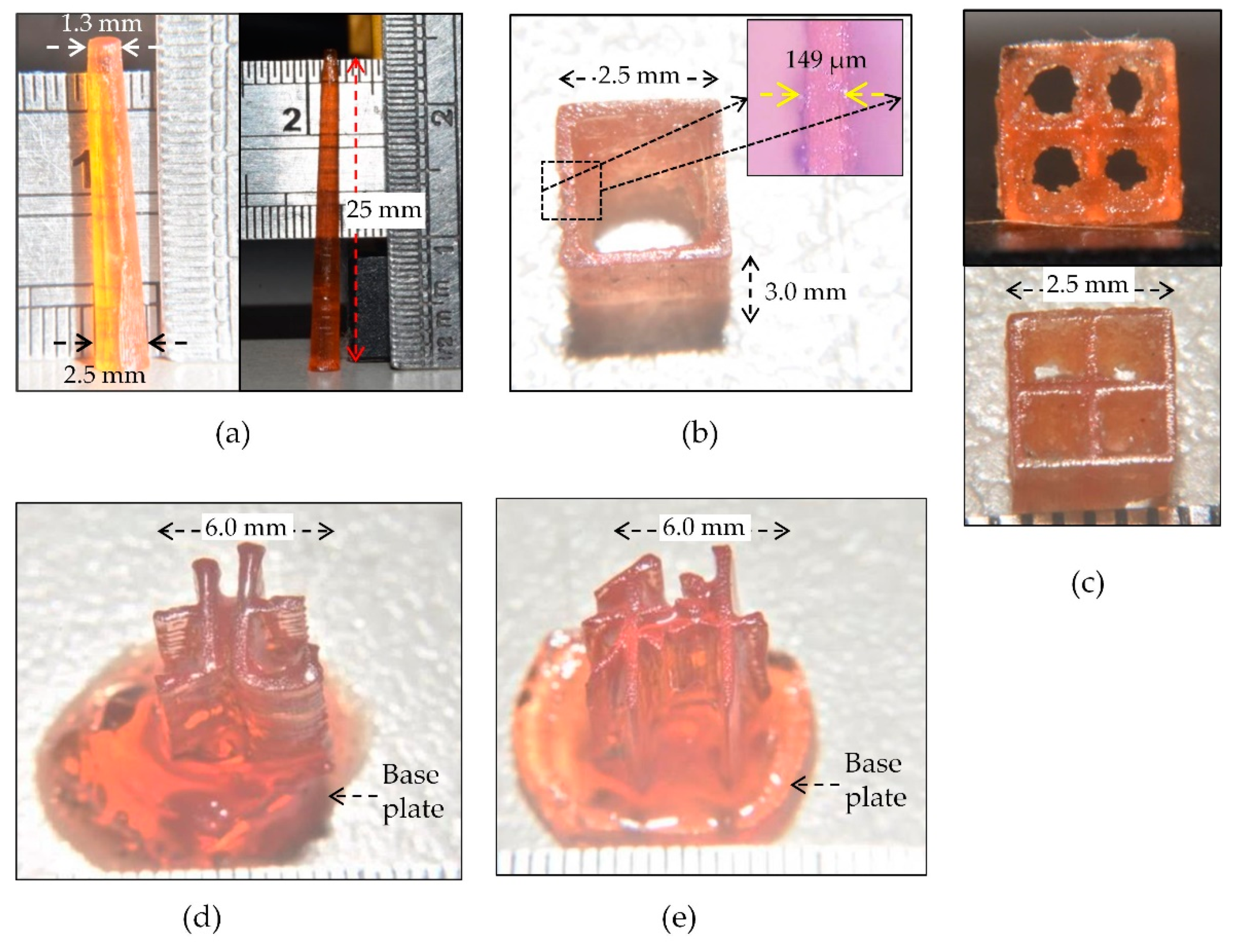
Figure 6 presents photopolymerized 3D objects fabricated in the current study.
Figure 6a shows two cones measuring 25 mm in length with a bottom width of 2.5 mm and top width of 1.3 mm, fabricated using the CGH in
Figure 4a. The intended length was 30 mm with an intended top width of 1.0 and bottom width of 2.6 mm. Unfortunately, we were unable to fulfill the length of the object, due to the limited capacity of the resin injector.
Figure 6b presents a rectangular pipe (2.5 mm × 2.5 mm × 3.0 mm) based on the CGH in
Figure 4b. The width of sidewall in the original pattern was 128 μm (6.4 μm × 20px), whereas the width of the sidewall in the resulting object was 149 μm.
Figure 6c shows an object similar to the one in
Figure 6b but with 2 × 2 rectangular pipes. The top surface of the object in
Figure 6b,c was well formed; however, the bottom of the object was degraded by leftover polymer under the effects of light reflected by the bottom glass of the beaker.
Figure 6d,e show two Chinese characters, representing “north” and “technology,” respectively, based on the CGHs in
Figure 4c,d. To prevent the characters from falling apart, we initially formed (via photo-polymerization) a base plate at the bottom of the characters. Despite the small size of the objects (6.0 mm × 6.0 mm × 7.0 mm), they both present good continuity in the transverse and axial directions.
5. Discussion
The achievable height of a 3D object depends on the number of sliced images and their spacing. The maximum number of sliced images calculated in the current study was nine; however, the number of sub-CGHs could be increased if necessary. Nevertheless, the spacing between image slices determines the optimization outcome of the compound CGH. Good axial continuity requires small spacing; however, this would increase the amount of inter-plane noise, which can degrade the lateral structure. Considering the pixel pitch, operating wavelength, and SLM window used in the study, spacing in the range of 3 to 10 mm would be ideal. Note also that the axial variation between the two patterns in adjacent planes was limited to 5° when using the apparatus in this study, due to the limitation of coherent wave propagation in a single direction.
Considering that the exposure time depends on the rate at which resin is introduced, when fabricating a 3D object with axial variation (e.g.,
Figure 4a), the introduction rate of resin must be adjusted to account for the optical power of the 2D images. In our experiments, we measured the optical power on four image planes, which revealed that the power in the largest circle was roughly one tenth of that in the smallest circle. By altering the rate at which resin was introduced into the system, we were able to fabricate the 3D cone shown in
Figure 6a. Clearly, the system requires real-time monitoring on power to control the introduction of resin during the fabrication of complex objects.
6. Conclusions
Existing additive manufacturing methods (i.e., 3D printing) are used to fabricate objects stepwise layer by layer. Photocuring methods (e.g., SLA and DLP) are frequently used when the 3D object is made of soft materials; however, the process tends to be time-consuming and introduces layering artifacts. Holographic 3D display (3DHD) reforms planar incident wavefronts into a 3D intensity distribution to create 3D images in space. In this paper, we present a novel 3DHD printing method based on near-field diffraction. The method uses a compound CGH to create a 3D image comprising multiple 2D sliced images. The compound CGH is created by individually calculating the sub-CGHs of 2D images using an iterative angular spectrum algorithm (IASA), whereupon the sub-CGHs are spatially interleaved and combined to form a compound CGH. After circular optimization of individual images, the compound CGH is displayed in an SLM to modulate the incident wavefronts in order to create a 3D layered image in the optical near field of the SLM. A 3D image comprising four 2D images was generated within a glass beaker, into which photopolymeric resin was gradually introduced, thereby eliminating the need for a mechanical stage to create 3D photopolymerized objects. In experiments, we created five photopolymerized objects with a maximum axial length of 25 mm and minimum feature width of 149 μm.
The proposed method features high efficiency, high resolution, rapid fabrication, and good continuity. The high light usage efficiency can be attributed to the fact that most of the optical power transmitted from a phase-only CGH contributes to the intensity distribution of the CGH image (i.e., negligible light loss). In addition, the laser source in the 3DHD system provides optical power at the specific wavelength required for polymerization, such that none of the transmitted light is wasted. The high resolution can be attributed to the achievable lateral resolution of CGH patterns (≈λ/2NA, where NA is the numerical aperture). The high fabrication speed can be attributed to the fact that the entire 3D optical intensity distribution is produced simultaneously, such that linear scanning is not required. Finally, the continuous nature of coherent waves in space minimizes the formation of artifacts in the resulting photopolymerized objects.
This study demonstrates the feasibility of the proposed 3DHD printing method; however, a number of issues have yet to be overcome, such as fabrication area and complexity in the axial direction. In the current study, the fabrication area was limited to the area of the SLM window, due to the angular spectrum method used in the design of CGHs. A larger fabrication area could be achieved using Fresnel or Fraunhofer diffraction; however, this would lead to a proportional increase in the axial spacing of the 2D sliced images. Axial complexity must be traded off against hardware costs. For example, complex 3D objects could be patterned using three CGH patterns directed from the x-, y-, and z-directions; however, the apparatus used to achieve this would be highly complex. Another issue pertaining to axial complexity is the spacing of 2D sliced images. Despite the axial resolution of scalar diffraction (≈2λ/NA2), the spacing of the sliced images is on the order of a few millimeters, due to the fact that these 2D patterns strongly degrade each other. Other practical challenges include optimizing resin for 532 nm laser light, fixing photopolymerized objects within the resin, and devising a systematic approach to resin injection.
Finally, inter-plane noise and speckles in 3D CGH images can seriously degrade image quality. Thus, fabricating high-quality objects with fine structures will require images with a high signal-to-noise ratio and highly uniform image intensity. Inter-plane noise could be reduced by eliminating the back propagation imposed by dc or twin image terms [
28]. We believe that optimization algorithms of greater sophistication [
29] in conjunction with speckle suppression methods [
30] could elevate the proposed method to levels of precision sufficient for the manufacture of highly intricate objects.
Author Contributions
Conceptualization, C.-F.L., W.-F.H. and R.-J.C.; methodology, W.-F.H. and C.-F.L.; software, T.-H.Y.; validation, W.-F.H. and R.-J.C.; formal analysis, W.-F.H.; investigation, W.-F.H.; resources, C.-F.L. and R.-J.C.; data curation, T.-H.Y. and W.-F.H.; writing—original draft preparation, W.-F.H.; writing—review and editing, W.-F.H.; visualization, T.-H.Y. and W.-F.H.; supervision, W.-F.H.; project administration, W.-F.H.; funding acquisition, W.-F.H. All authors have read and agreed to the published version of the manuscript.
Funding
This research was funded by the Ministry of Science and Technology, Taiwan, grant numbers 104-2221-E-027-084-MY3 and 108-2221-E-027-099-MY3.
Institutional Review Board Statement
Not applicable.
Informed Consent Statement
Not applicable.
Data Availability Statement
Not available.
Acknowledgments
The authors would like to thank Jeng-Ywan Jeng, National Taiwan University of Science and Technology, for providing the photocurable resin for 3D printing.
Conflicts of Interest
The authors declare no conflict of interest.
Appendix A. Abbreviations and Symbols
| 3DHD | holographic three-dimensional display |
| AM | additive manufacturing |
| ASM | angular spectrum method |
| CGH | computer-generated hologram |
| DOE | diffractive optical element |
| DOP | diffractive optics processing |
| DLP | digital light processing |
| IASA | iterative angular spectrum algorithm |
| SLA | stereolithographic appearance |
| SLM | spatial light modulator |
| A(fx, fy; z) | angular spectrum of U(x, y, z) |
| U(x, y, z) | complex amplitude distribution of optical field in z plane |
| k | wave number (2π/λ) |
| (α, β, γ) | direction cosines |
| λ | wavelength |
| AS{} & AS−1{} | operators of angular spectrum and inverse angular spectrum |
| & | operators of Fourier and inverse Fourier transform |
| Q[]{} | operators of multiplication of a quadratic-phase exponential |
References
- Pan, Y.; Liu, J.; Li, X.; Wang, Y. A review of dynamic holographic three-dimensional display: Algorithms, devices, and systems. IEEE Trans. Ind. Informat. 2016, 12, 1599–1610. [Google Scholar] [CrossRef]
- Zheng, X.; Deotte, J.; Alonso, M.P.; Farquar, G.R.; Weisgraber, T.R. Design and optimization of a light-emitting diode projection micro-stereolithography three-dimensional manufacturing system. Rev. Sci. Instrum. 2012, 83, 125001. [Google Scholar] [CrossRef] [PubMed]
- Truby, R.L.; Lewis, J.A. Printing soft matter in three dimensions. Nature 2016, 540, 371–378. [Google Scholar] [CrossRef] [PubMed]
- Ngo, T.D.; Kashani, A.; Imbalzano, G.; Nguyen, K.T.Q.; Hui, D. Additive manufacturing (3D printing): A review of materials, methods, applications and challenges. Compos. Part B 2018, 143, 172–196. [Google Scholar] [CrossRef]
- Flamm, D.; Grossmann, D.G.; Sailer, M.; Kaiser, M.; Zimmermann, F.; Chen, K.; Jenne, M.; Kleiner, J.; Hellstern, J.; Tillkorn, C.; et al. Structured light for ultrafast laser micro- and nanoprocessing. Opt. Engineer. 2021, 60, 025105. [Google Scholar]
- Hull, C.W. Apparatus for Productionof Three-Dimensional Objects by Stereolithography. US Patent 4,575,330, 11 March 1986. [Google Scholar]
- Manapat, J.Z.; Chen, Q.; Ye, P.; Advincula, R.C. 3D printing of polymer nanocomposites via stereolithography. Macromol. Mater. Eng. 2017, 302, 1600553. [Google Scholar] [CrossRef]
- Maruyama, T.; Hirata, H.; Furukama, T.; Maruo, S. Multi-material microstereolithography using a palette with multicolor photocurable resins. Opt. Mater. Express 2020, 10, 2522–2532. [Google Scholar] [CrossRef]
- Chen, Y.; Furukawa, T.; Ibi, T.; Noda, Y.; Maruo, S. Multi-scale micro-stereolithography using optical fibers with a photocurable ceramic slurry. Opt. Mater. Express 2021, 11, 105–114. [Google Scholar] [CrossRef]
- Ahn, D.; Stevens, L.M.; Zhou, K.; Page, Z.A. Rapid high-resolution visible light 3D printing. ACS Cent. Sci. 2020, 6, 1555–1563. [Google Scholar] [CrossRef]
- Caprioli, M.; Roppolo, I.; Chiappone, A.; Larush, L.; Pirri, C.F.; Magdassi, S. 3D-printed self-healing hydrogels via digital light processing. Nat. Commun. 2021, 12, 2462. [Google Scholar] [CrossRef]
- Sun, C.; Fang, N.; Wu, D.M.; Zhang, X. Projection micro-stereolithography using digital micro-mirror dynamic mask. Sens. Actuat. A 2005, 121, 113–120. [Google Scholar] [CrossRef]
- Tumbleston, J.R.; Shirvanyants, D.; Ermoshkin, N.; Janusziewicz, R.; Johnson, A.R.; Kelly, D.; Chen, K.; Pinschmidt, R.; Rolland, J.P.; Ermoshkin, A.; et al. Continuous liquid interface production of 3D objects. Science 2015, 347, 1349–1352. [Google Scholar] [CrossRef] [PubMed]
- Kelly, B.E.; Bhattacharya, I.; Heidari, H.; Shusteff, M.; Spadaccini, C.M.; Taylor, H.K. Volumetric additive manufacturing via tomographic reconstruction. Science 2019, 363, 1075–1079. [Google Scholar] [CrossRef] [PubMed]
- Shusteff, M.; Browar, A.E.M.; Kelly, B.E.; Henriksson, J.; Weisgraber, T.H.; Panas, R.M.; Fang, N.X.; Spadaccini, M. One-step volumetric additive manufacturing of complex polymer structures. Sci. Adv. 2017, 3, eaao5496. [Google Scholar] [CrossRef] [Green Version]
- Kim, S.-C.; Kim, E.-S. Effective generation of digital holograms of three-dimensional objects using a novel look-up table method. Appl. Opt. 2008, 47, D55–D62. [Google Scholar] [CrossRef]
- Zheng, H.; Yu, Y.; Wang, T.; Asundi, A. Computer-generated kinoforms of real-existing full-color 3D objects using pure-phase look-up-table method. Opt. Laser Technol. 2012, 50, 568–573. [Google Scholar] [CrossRef]
- Zhao, Y.; Cao, L.; Zhang, H.; Kong, D.; Jin, G. Accurate calculation of computer-generated holograms using angular-spectrum layer-oriented method. Opt. Express 2015, 23, 25440–25449. [Google Scholar] [CrossRef]
- Jia, J.; Si, J.; Chu, D. Fast two-step layer-based method for computer generated hologram using sub-sparse 2D fast Fourier transform. Opt. Express 2018, 26, 17487–17497. [Google Scholar] [CrossRef]
- Gilles, A.; Gioia, P. Real-time layer-based computer-generated hologram calculation for the Fourier transform optical system. Appl. Opt. 2018, 57, 8508–8517. [Google Scholar] [CrossRef]
- Xiao, D.; Li, X.-W.; Wang, D.; Wang, Y.; Wang, Q.-H. Three-dimensional holographic hiding and display using layer-oriented theorem. Opt. Commun. 2019, 453, 124340. [Google Scholar] [CrossRef]
- Nishi, H.; Matsushima, K.; Nakahara, S. Rendering of specular surfaces in polygon-based computer-generated holograms. Appl. Opt. 2011, 34, H245–H252. [Google Scholar] [CrossRef]
- Lu, Z.; Sakamoto, Y. Holographic display methods for volume data: Polygon-based and MIP-based methods. Appl. Opt. 2018, 57, A142–A149. [Google Scholar] [CrossRef]
- Rodrigo, J.A.; Alieva, T.; Abramochkin, E.; Castro, I. Shaping of light beams along curves in three dimensions. Opt. Express 2013, 21, 20544–20555. [Google Scholar] [CrossRef] [Green Version]
- Goodman, J.W. Introduction to Fourier Optics, 3rd ed.; Roberts & Co.: Englewood, CO, USA, 2005; pp. 55–61, 97–126. [Google Scholar]
- Mellin, S.D.; Nordin, G.P. Limits of scalar diffraction theory and an iterative angular spectrum algorithm for finite aperture diffractive optical element design. Opt. Express 2001, 8, 705–722. [Google Scholar] [CrossRef]
- Jeng, J.-Y.; Jhang, F.-T.; Shafikova, R.; Tri, S. Photocurable Resin and Three-Dimensional Printing System. US Patent 9,987,839 B2, 2018. [Google Scholar]
- Birdi, J.; Rajora, S.; Butola, M.; Khare, K. True 3D reconstruction in digital holography. J. Phys. Photonics 2020, 2, 044004. [Google Scholar] [CrossRef]
- Hsu, W.-F.; Lin, S.-T.; Lin, J.-F. Optimization of diffractive optical elements with millions of pixels using progressive error reduction algorithm (PERA). Opt. Laser Eng. 2019, 122, 49–58. [Google Scholar] [CrossRef]
- Chang, Y.-S.; Hsu, W.-F.; Hsu, K.-H.; Lin, H.Y. Full-frame projection displays using a liquid-crystal-on-silicon spatial light modulator for beam shaping and speckle suppression. Appl. Opt. 2014, 53, G214–G221. [Google Scholar] [CrossRef] [PubMed]
| Publisher’s Note: MDPI stays neutral with regard to jurisdictional claims in published maps and institutional affiliations. |
© 2021 by the authors. Licensee MDPI, Basel, Switzerland. This article is an open access article distributed under the terms and conditions of the Creative Commons Attribution (CC BY) license (https://creativecommons.org/licenses/by/4.0/).


