
Holographic Display System to Suppress Speckle Noise Based on Beam Shaping

School of Instrumentation and Optoelectronic Engineering, Beihang University, Beijing 100191, China
*
Author to whom correspondence should be addressed.
Photonics 2021, 8(6), 204; https://doi.org/10.3390/photonics8060204
Submission received: 7 May 2021
/
Revised: 2 June 2021
/
Accepted: 4 June 2021
/
Published: 6 June 2021
(This article belongs to the Special Issue Holography)
Abstract
:In this paper, a holographic system to suppress the speckle noise is proposed. Two spatial light modulators (SLMs) are used in the system, one of which is used for beam shaping, and the other is used for reproducing the image. By calculating the effective viewing angle of the reconstructed image, the effective hologram and the effective region of the SLM are calculated accordingly. Then, the size of the diffractive optical element (DOE) is calculated accordingly. The dynamic DOEs and effective hologram are loaded on the effective regions of the two SLMs, respectively, while the wasted areas of the two SLMs are performed with zero-padded operations. When the laser passes through the first SLM, the light can be modulated by the effective DOEs. When the modulated beam illuminates the second SLM which is loaded with the effective hologram, the image is reconstructed with better quality and lower speckle noise. Moreover, the calculation time of the hologram is reduced. Experiments indicate the validity of the proposed system.
1. Introduction
Recent years have witnessed a massive growth in the display industry, and three-dimensional (3D) display has gradually become the next generation display technology that attracts more and more attention [1,2,3]. Among all the display technologies, computer-generated holography (CGH) is one of the most promising ones and viewed as the ultimate goal of the 3D display, because it can reproduce an arbitrary object, whether real or virtual, with all the depth cues [4,5]. CGH technology usually records the object information by means of interference, and then reconstructs the object by the principle of diffraction [6,7]. So far, although some progress has been made in holographic display, there are still several problems that restrict its further development. For example, speckle noise caused by laser coherence will lead to poor quality and less sharpness of the reconstructed image [8,9,10]. To reduce the speckle noise, some researchers use the time multiplexing method to reconstruct the multiple holograms [11,12]. However, this method may cause blurring or flickering of the reconstructed image due to inability of the spatial light modulator (SLM) to refresh fast enough. An iterative algorithm is also proposed so as to suppress the speckle noise of the reconstructed image [13,14], while too many iterations will result in a slower calculation speed. Besides, speckle noise suppression can also be realized by using an LED light source instead of the lasers [15,16], but at the cost of limited brightness. The error diffusion method also serves as a valid way to suppress speckle noise [17]. The pixel separation method suppresses the speckle noise by eliminating the interference between the adjacent image points [18]. Due to the long calculation time of holograms, it is quite hard to realize a real-time holographic display [19]. In order to achieve fast calculation of holograms, a look-up table algorithm is proposed [20]. The wave front recording algorithm converts most of the diffraction calculation into planar propagation [21,22] and uses the fast convolution calculation to reduce the calculation time. The novel look-up table method (NLUT) making full use of the translational characteristics is also proposed in order to reduce the memory size and improve the calculation speed further [23,24,25]. By taking advantage of the translational properties of the holograms, redundant calculations between different frames of a dynamic video can be reduced. Despite all the efforts, real-time high-quality holographic display with fast calculation speed is still out of reach at the present time [26,27,28].
In this paper, a holographic system based on beam shaping by using two SLMs to suppress the speckle noise is proposed. One SLM is used in the system for the beam shaping and the other is used for reproducing the image. After analyzing and calculating the effective perspective of the reconstructed image, the size of the diffractive optical elements (DOE) can be calculated. The dynamic DOEs and effective hologram are loaded on the effective regions of the two SLMs, respectively, while the wasted areas of the SLMs are performed with zero-padded operations. When the modulated beam illuminates the effective hologram, the reconstructed image can be displayed with lower speckle noise. Moreover, the calculation speed of the hologram is improved.
2. Mechanism and Operating Principle
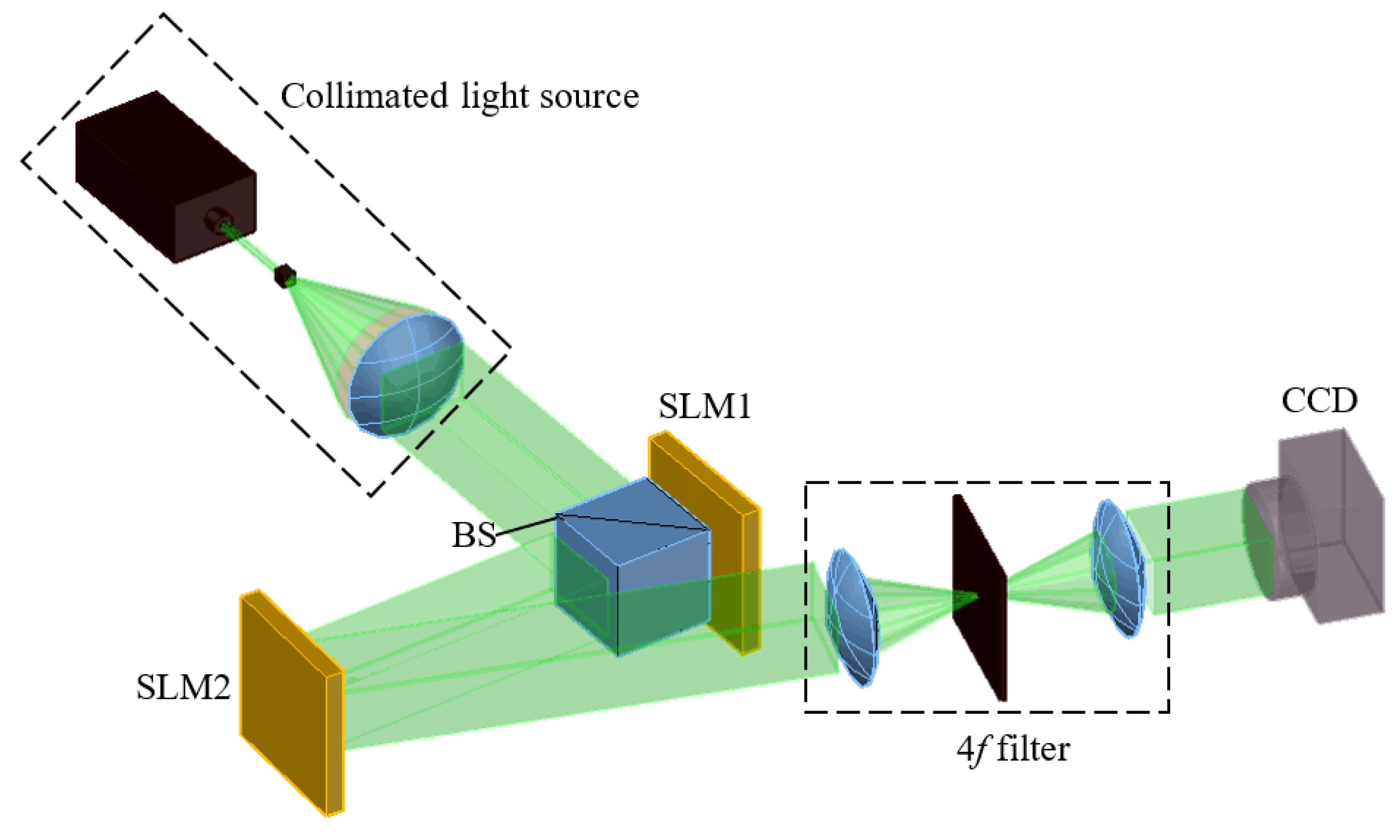
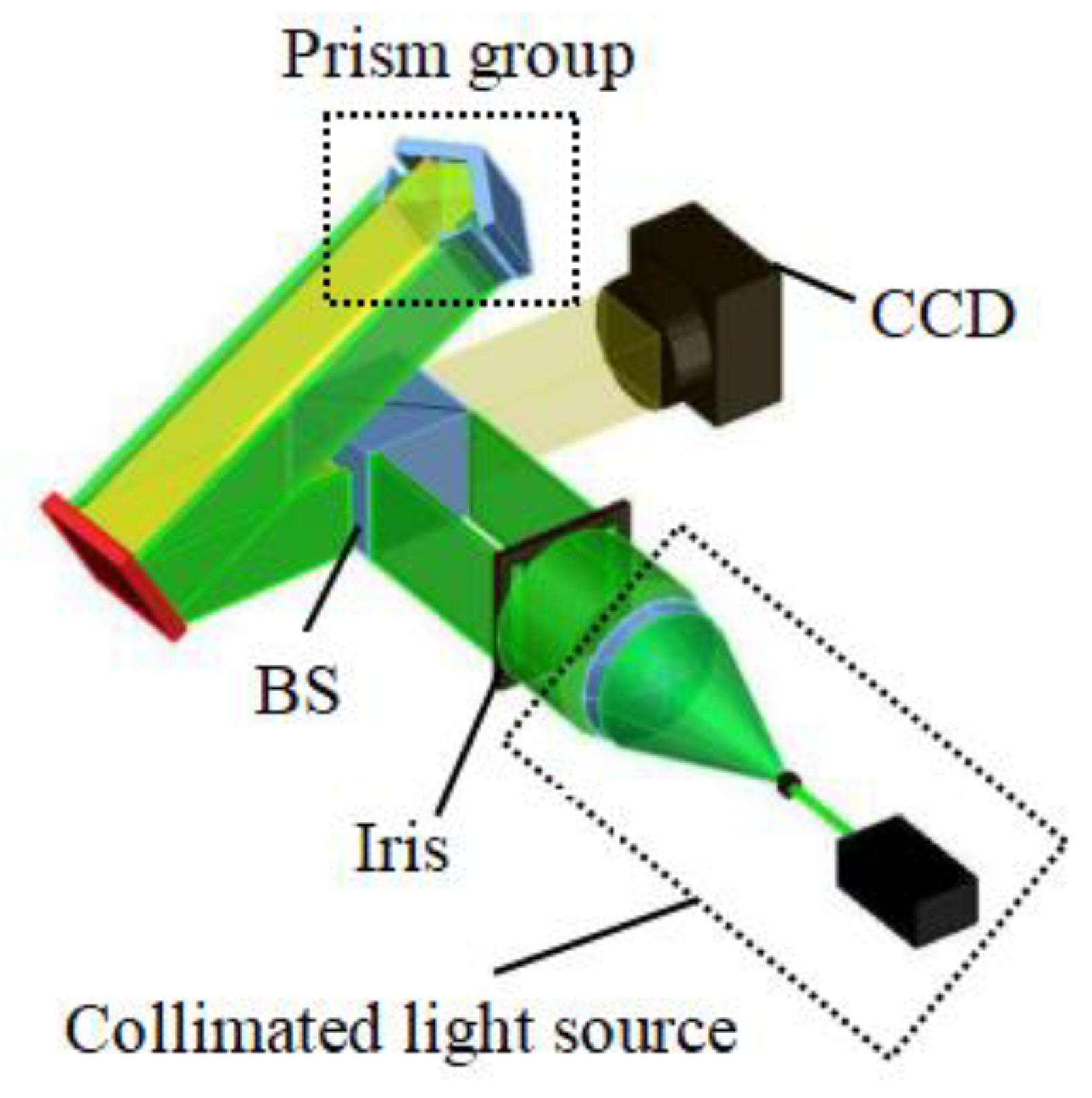
The structure of our proposed system is depicted in Figure 1. It is composed of a collimated light source, a beam splitter (BS), two SLMs, a 4f filter and a CCD. The collimated light source is used to provide a plane wave. When the collimated light propagates through the BS and SLM1, the light can be modulated by the dynamic DOEs loaded on SLM1. The positions of the two SLMs require precise alignment. Then, the modulated light can illuminate SLM2 after the reflection of SLM1. To achieve the purpose of speckle noise suppression, the effective hologram and the effective region of the SLM are calculated, respectively. The effective hologram and dynamic DOEs are added to the effective regions of the two SLMs accordingly, while the wasted areas of the SLMs are performed with zero-padded operations. Finally, the diffracted light will propagate through a 4f filter and then be detected by CCD.
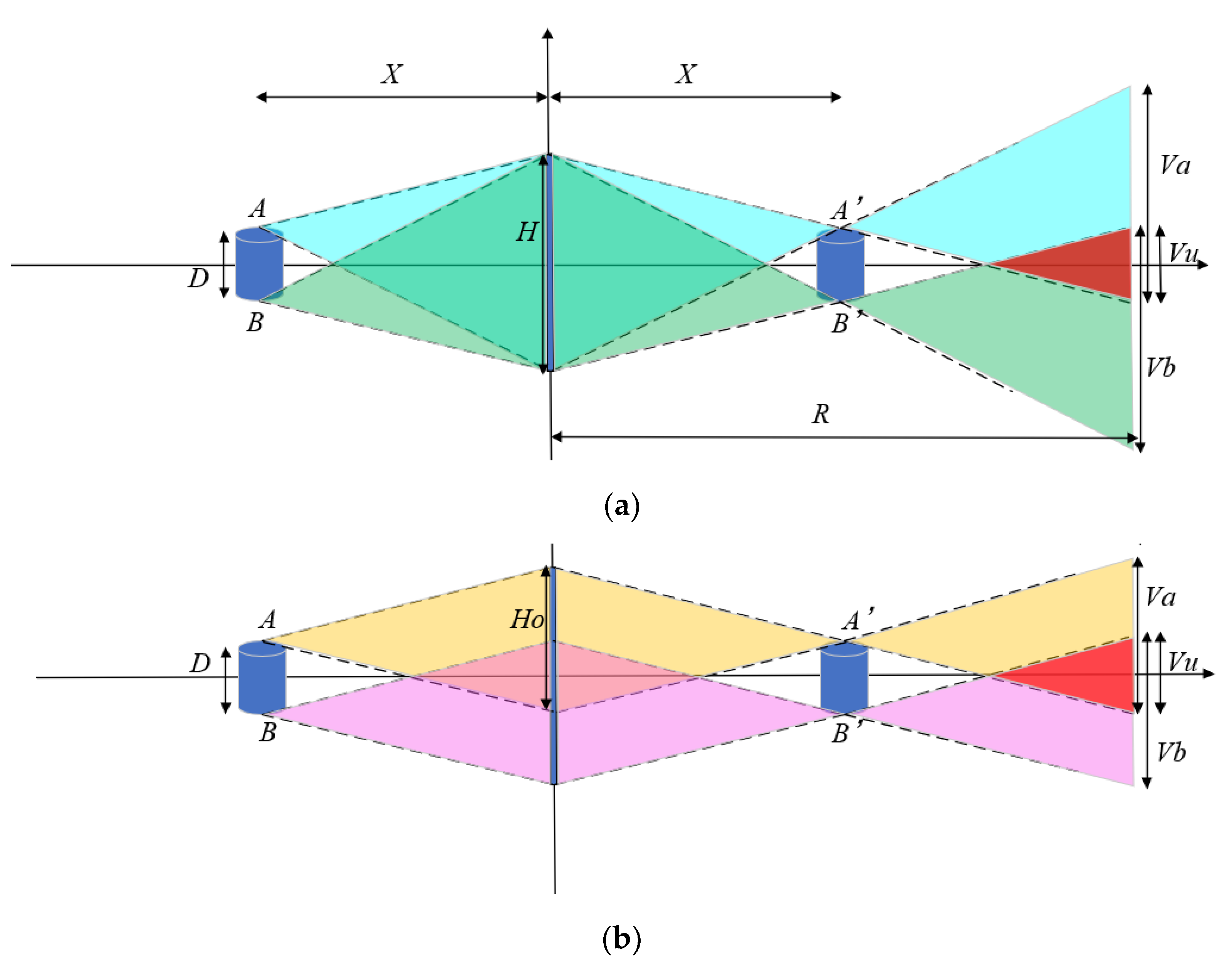
In order to calculate the effective region in SLM2, which is decisive for the reconstruction, the effective perspective during observation of the reconstructed image needs to be analyzed. The principle of the effective perspective is shown in Figure 2. According to diffraction theory, the size of the CGH is the same as the size of the SLM used in two essential holographic processes, which are recording the information of the object and reconstructing the object. A coordinate system is built by using the core of the SLM as the origin. D is the breadth of the recorded object, X equals to the diffraction range, H is the breadth of the SLM, and A and B represent the vertex and the lowest point of the recorded object, respectively. When recording the information of the object, different diffraction fringes store the information of each point and build up to the whole hologram plane. The borders of the diffracted light of point A and point B are expressed as blue and green dotted curves, respectively. During reproduction, the reproduced image will be clearly reproduced at the diffraction position of distance Z. Point A’ and point B’ are the vertex and the lowest point of the reproduced images corresponding to the point A and B, respectively.
When the viewer observes the reproduced images at the location that is R away behind the SLM, the breadth of the viewing area is recorded as V. According to the diffraction principle, Va is the blue area where a viewer can observe the reproduced image A’. The area where viewers can observe the reproduced image B’ is expressed as Vb in green. It is only in the overlapping area of Va and Vb (area Vu) that the viewer is able to observe the entire reproduced image. Outside Vu, the viewer can only observe the incomplete reproduced image, which means this part of information is useless. Therefore, the area Vu is regarded as the effective perspective and it can be expressed as follows:
Vu = Va + Vb − V
However, the useless information not only takes a lot of time during calculation but also increases the speckle noise. Then, for the point A’, the corrected diffracted area is painted in yellow, with dotted curves as the light edges. For the point B’, the area is painted in pink. According to the geometric relationship, it can be clearly seen that the area of the wasted information is reduced while the effective area remains the same. To obtain the corrected diffracted light, we reduce the size of diffraction fringe patterns of object points. In addition, the width of the diffraction fringe pattern is Ho = H − D. In the proposed system, the NLUT algorithm is used to calculate the object fringe pattern [25]. Different from the conventional NLUT method, the resolution of the pre-calculated principal fringe pattern (PFP) is smaller compared with the one of the SLM in the traditional method. Because of the property of shift-invariance, the effective hologram could then be calculated by shifting and adding PFP. The PFP is regarded as the Fresnel diffraction fringe pattern and it is precalculated and stored at the center point of the same depth plane. The PFP can be calculated as follows:
where x and y denote the coordinates of the object point on the hologram planes. k0 = 2π/λ represents the wavenumber. z represents the diffraction distance. Then, the effective hologram of all points can be calculated by the translation and addition operation of the PFPs.
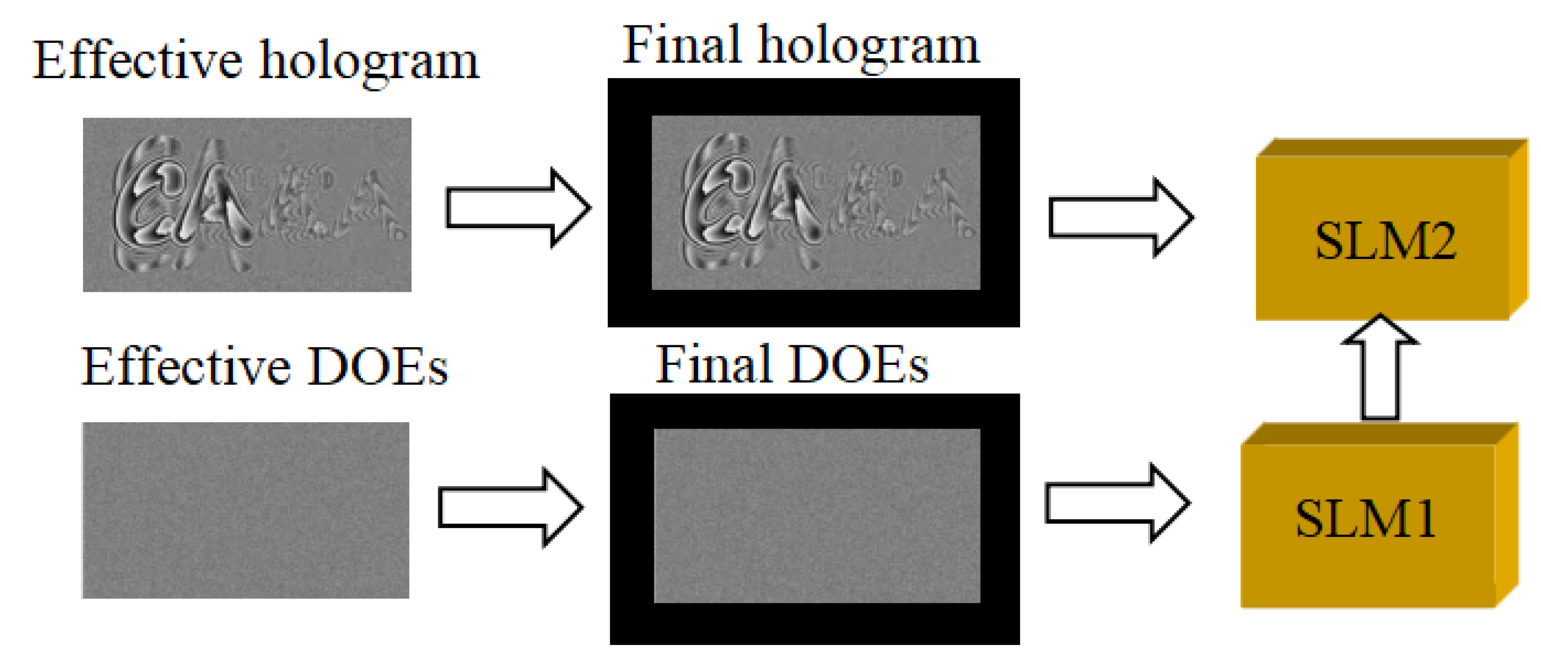
To achieve the aim of speckle noise suppression and utilize the SLM effectively, only the information which can be displayed at the area Vu is calculated to generate the hologram. Then, the effective hologram and effective region of the SLM can be obtained based on the geometric relationship, which is smaller compared with the initial hologram. For SLM1, we set the size of the DOEs to be equal to that of the effective hologram. The random phase distribution is recorded on the DOEs, so the coherence of the laser can be reduced. By using MATLAB, different random phase grayscales are generated. Then, different effective DOEs can be generated separately. For SLM2, the effective hologram is generated. Since the sizes of the effective hologram and DOEs are smaller than those of the two SLMs, in the wasted area around the effective hologram and DOEs, zero-padded operations are performed, as shown in Figure 3. The final DOEs are dynamically loaded on SLM1 and the final hologram is loaded on SLM2. So, the light is modulated by SLM1 and illuminates on SLM2. When n DOEs are loaded on SLM1, n images can be reconstructed and form the superimposed image through time multiplexing. The contrast can be expressed by the following equation:
where C and C0 represent the speckle noise contrast of the final image and the original image, respectively. In this way, the reproduced image is shown with less speckle noise and shorter calculation time.
3. Experiments and Results
In the experiments, the collimated light source has a wavelength of 532 nm. The SLM has a pixel pitch of 6.4 μm and a resolution of 1920 × 1080. The SLM with an addressable gray level of 256 (8 bit) is able to refresh at the rate of 60 Hz and modulate the phase within the range of [0, 2π]. The two SLMs have the same model. The BS, with a transmission of 80%, has a cube size of 25.4 mm × 25.4 mm × 25.4 mm. The 4f filter contains two solid lenses and an aperture. The distance between the SLM2 and the CCD is 20 cm.
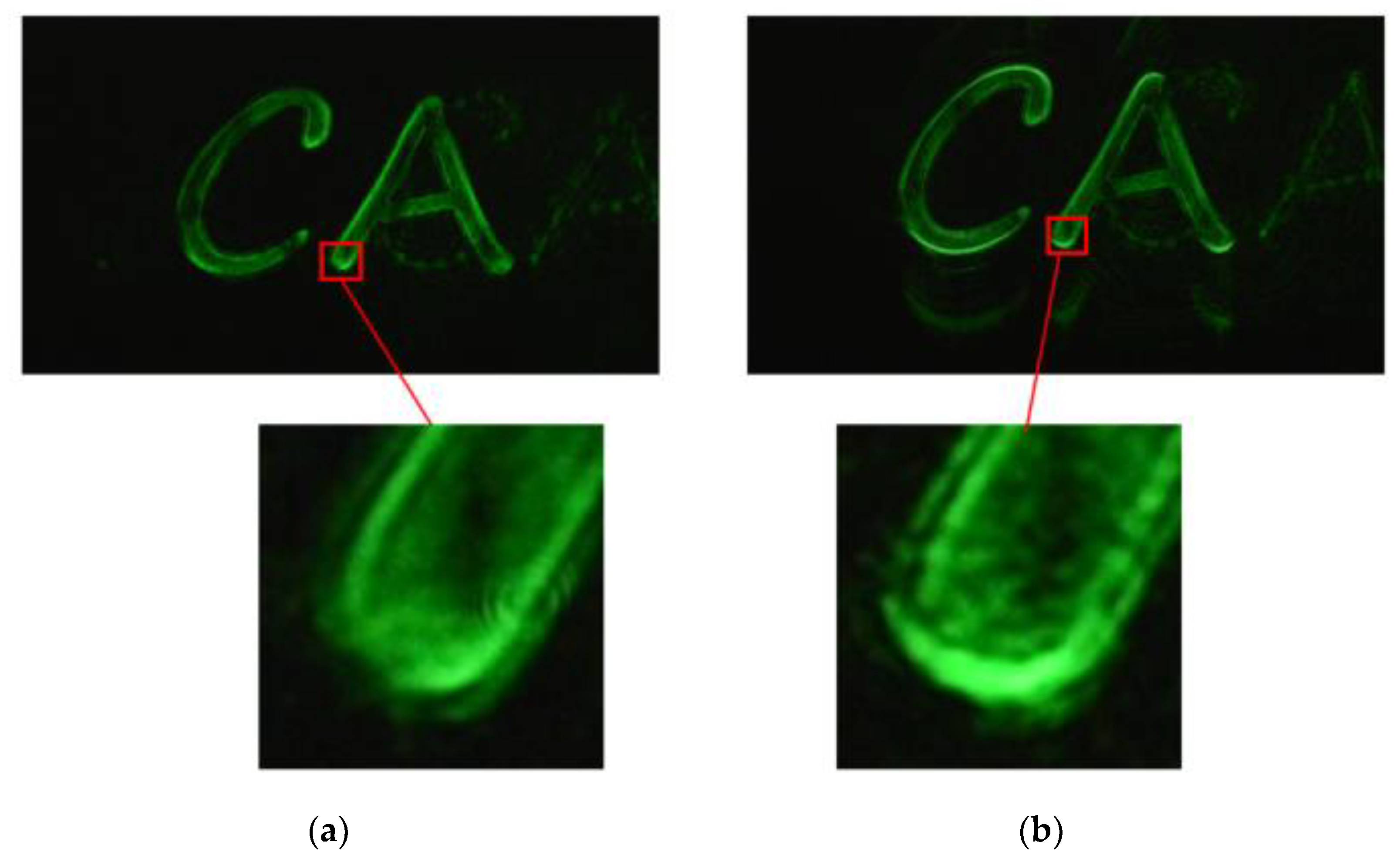
The resolution of the recorded object and the effective point number are 320 × 240 and 9119, respectively. Before calculating the PFP with a resolution of 1600 × 840, we first calculate the central point of the object. Figure 4a,b shows the results of the reproduced image making use of the traditional NLUT algorithm and the algorithm based on effective perspective computation, respectively. As can be seen from the results, compared with the traditional NLUT algorithm, the reproduced image can also be obtained with a better quality by using the algorithm based on our calculation. To better illustrate the merits of our proposed algorithm, we magnify parts of the reconstructed images to show the details. It is clear that the image quality using the effective perspective algorithm is as good as the NLUT algorithm. However, the contrast of the edge image of Figure 4b is better compared with the edge image of Figure 4a. Besides, the calculation time of the hologram based on the effective perspective calculation is reduced by 40.94%. So, the algorithm can reduce the computational time greatly under the premise of ensuring the image quality.
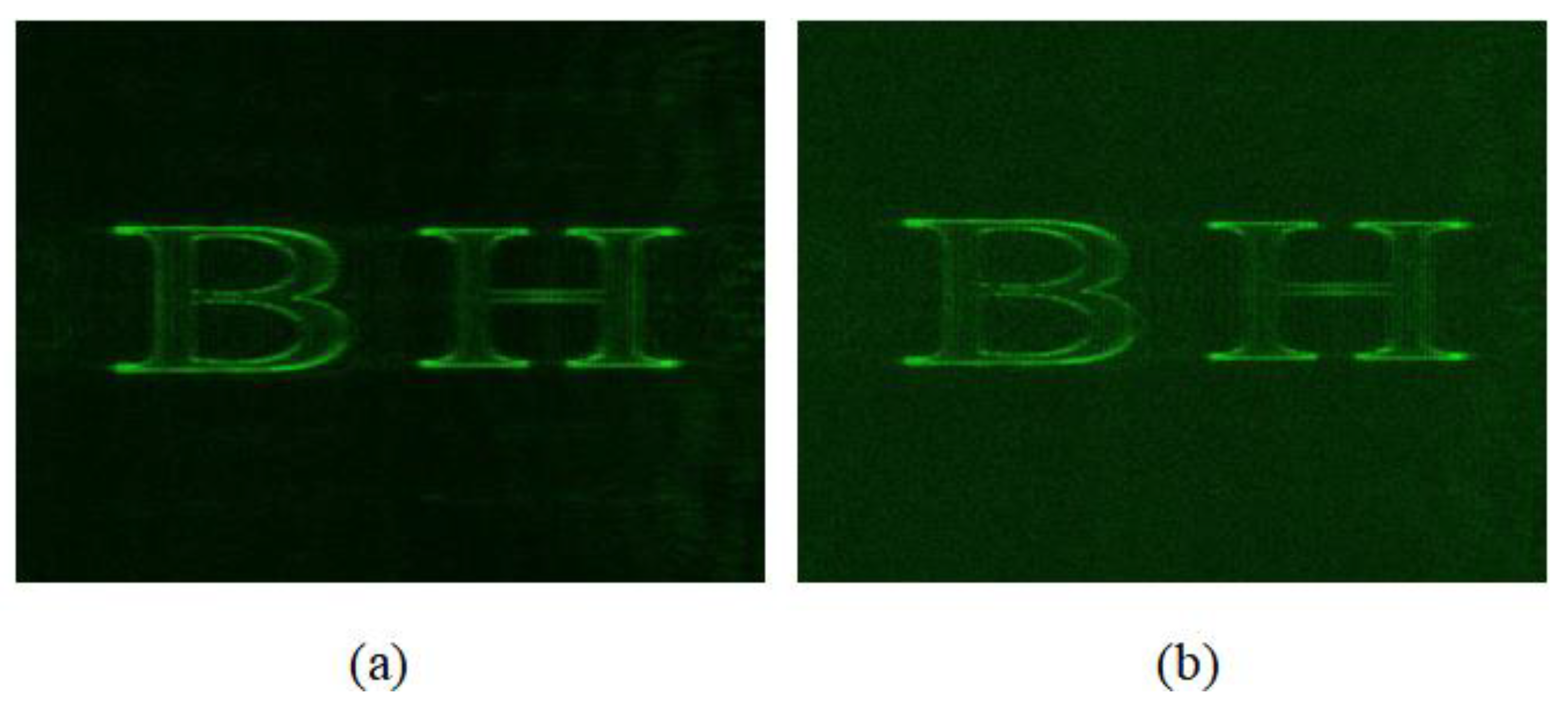
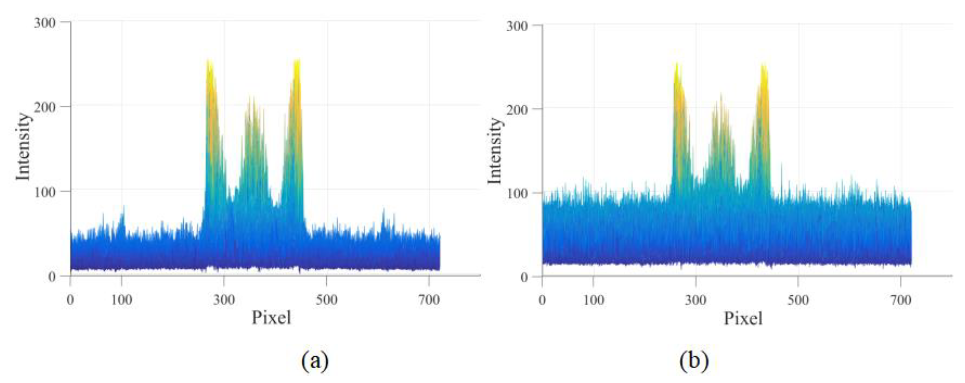
Then, the final hologram with the resolution of 1920 × 1080 is generated, where the “wasted resolution” of the hologram is 320 × 240. For the wasted area, the DOEs are generated to suppress the speckle noise. Figure 5 illustrates the simulation result of the reconstructed image, while Figure 5a corresponds to the result by utilizing the proposed system, and Figure 5b is the result without loading the DOEs. Besides, the intensities of the simulation results are given, as illustrated in Figure 6. The result indicates that the proposed system can suppress the speckle noise.
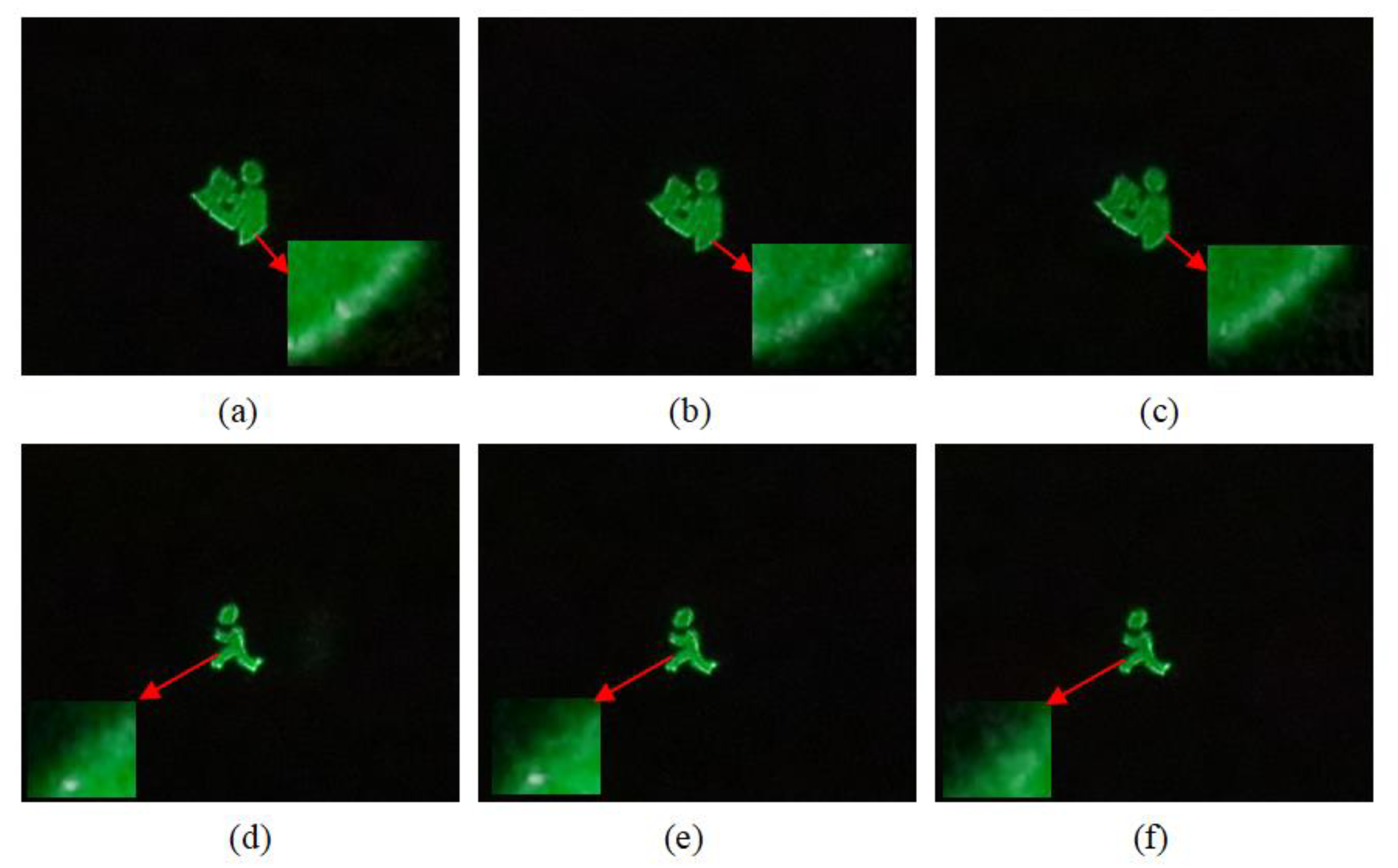
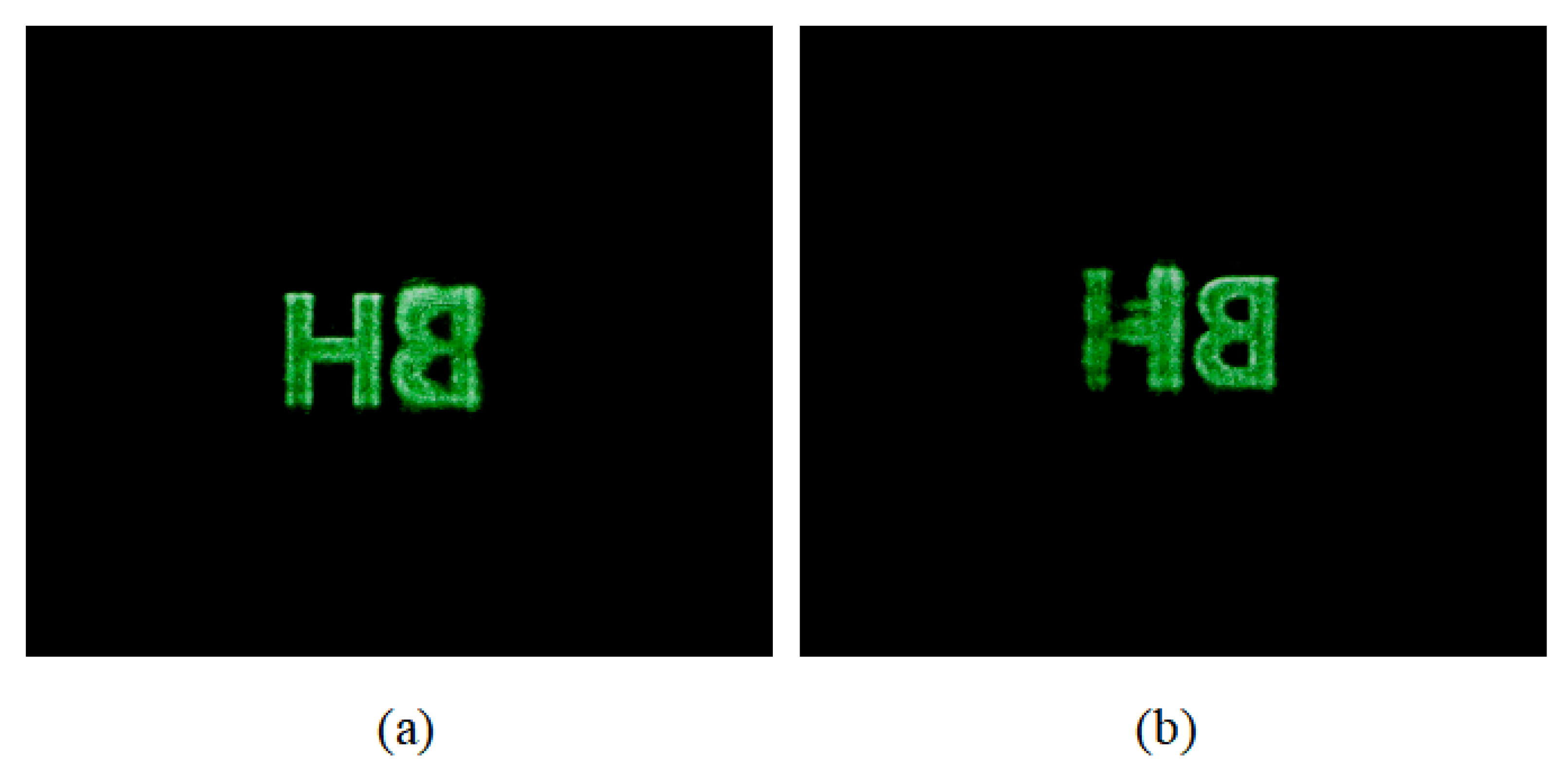
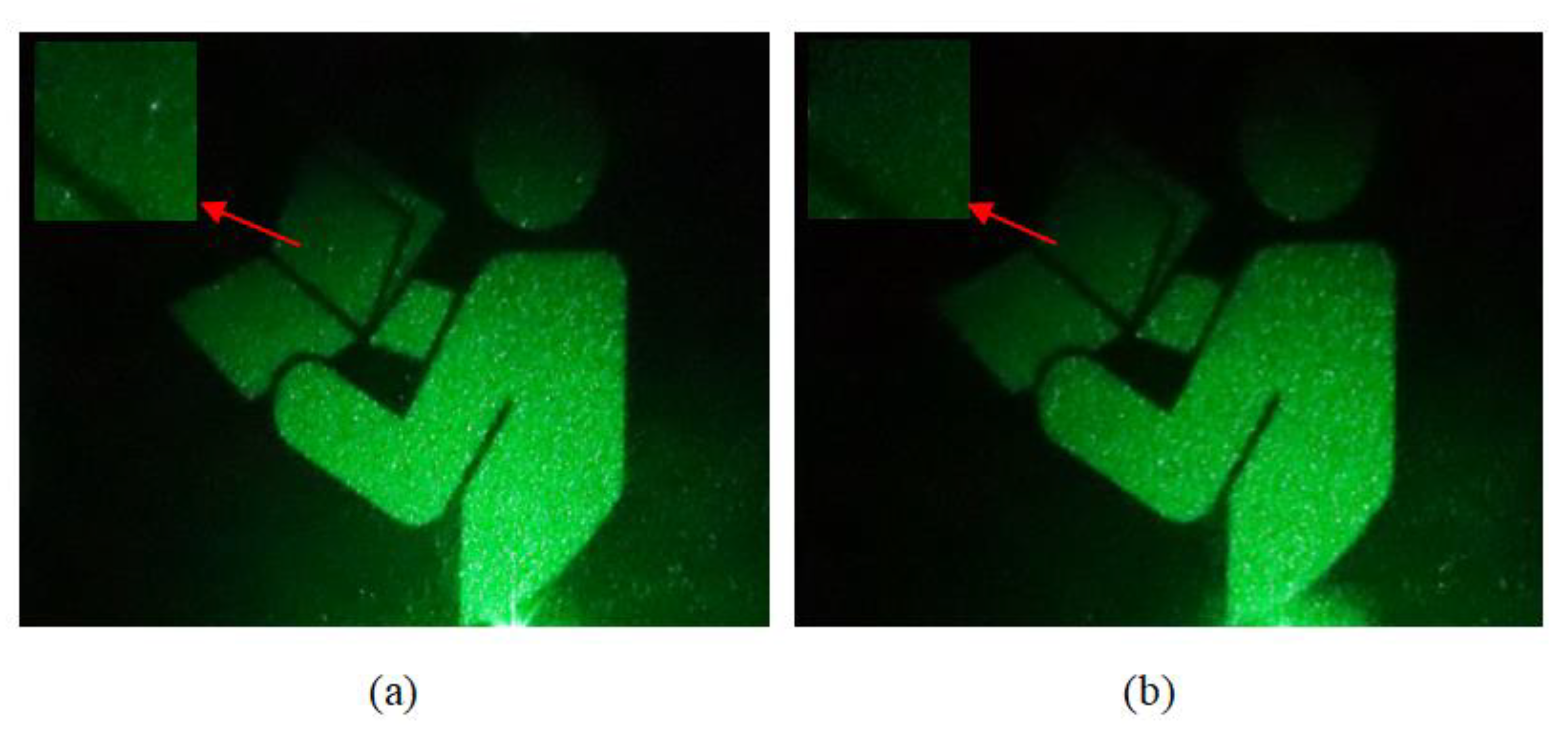
The optical experiment is also conducted, and the reconstructed image can be captured by the CCD, as illustrated in Figure 7. When DOE is not loaded, we only need to turn off SLM1 in the experiment. At this time, the light is not modulated by SLM1. The light reflected by SLM1 directly illuminates SLM2. Figure 7a,d corresponds to the results of loading the full holograms without DOEs. Figure 7b,e corresponds to the results of loading the effective hologram without DOEs. Figure 7c,f shows the results of loading the effective hologram with DOEs. For a better observation, we enlarged details of the images. As can be seen from the results, by using our proposed system, we successfully reduced the speckle noise. Besides, the 3D object is reproduced by using the proposed system and the reproduced image is able to be shown on the receiving screen. In the experiment, we choose the letters “BH” as the 3D object, where “B” and “H” are located at two different depths. The resolution is 320 × 240 and the depth is 6.4 cm. The horizontal and vertical resolution of the final hologram are 1920 and 1080, respectively. Results of the reproduced letters are shown in Figure 8, where Figure 8a is the picture captured when “H” is focused and Figure 8b is the one when “B” is focused. Since the maximum diffraction angle of the reconstructed image is limited by the SLM, when the pixel pitch of SLM is 6.4 μm and the wavelength is 532 nm, the maximum diffraction angle of the reconstructed image is ~2.38°. Then, the NA of the system is determined by the maximum diffraction angle accordingly.
In the above experiments, we use the NLUT algorithm for verification and comparison. To further illustrate the feasibility of our proposed system, the Gerchberg–Saxton (GS) algorithm is used for verification. In order to achieve near-field diffraction, a solid lens is placed behind SLM2 and the experimental results are illustrated in Figure 9. Figure 9a is the result of loading the hologram without DOEs, and Figure 9b is the result of using the proposed technology. By magnifying the details, it can be clearly seen that there is more noise in the traditional method. The reproduced image in Figure 9b is relatively uniform. In addition, the peak signal to noise ratio (PSNR) of the reproduced image is analyzed when the number of the DOEs is changed. When no DOEs are loaded on SLM1, the PSNR is ~9.9634. When the number of the DOEs is 3 and 9, the PSNR of the reproduced image is ~11.0349 and ~12.0663. So, the speckleless image could be generated by loading the DOEs on SLM1 and the effective hologram on SLM2, respectively. The proposed system also adapts to other algorithms.
4. Discussion
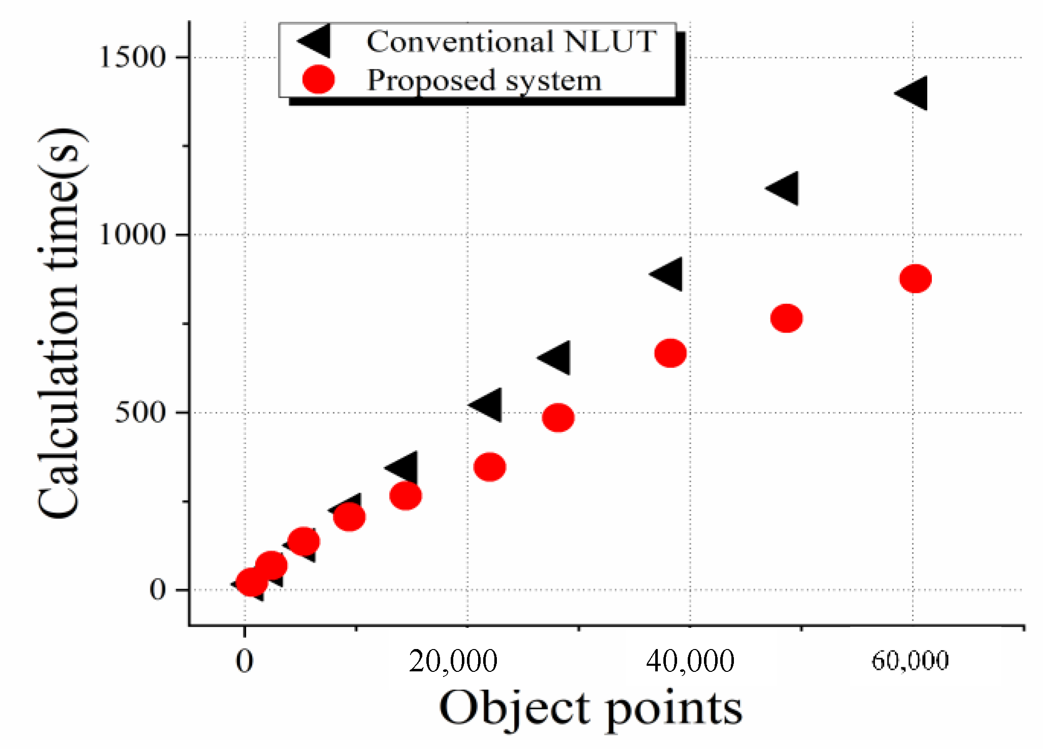
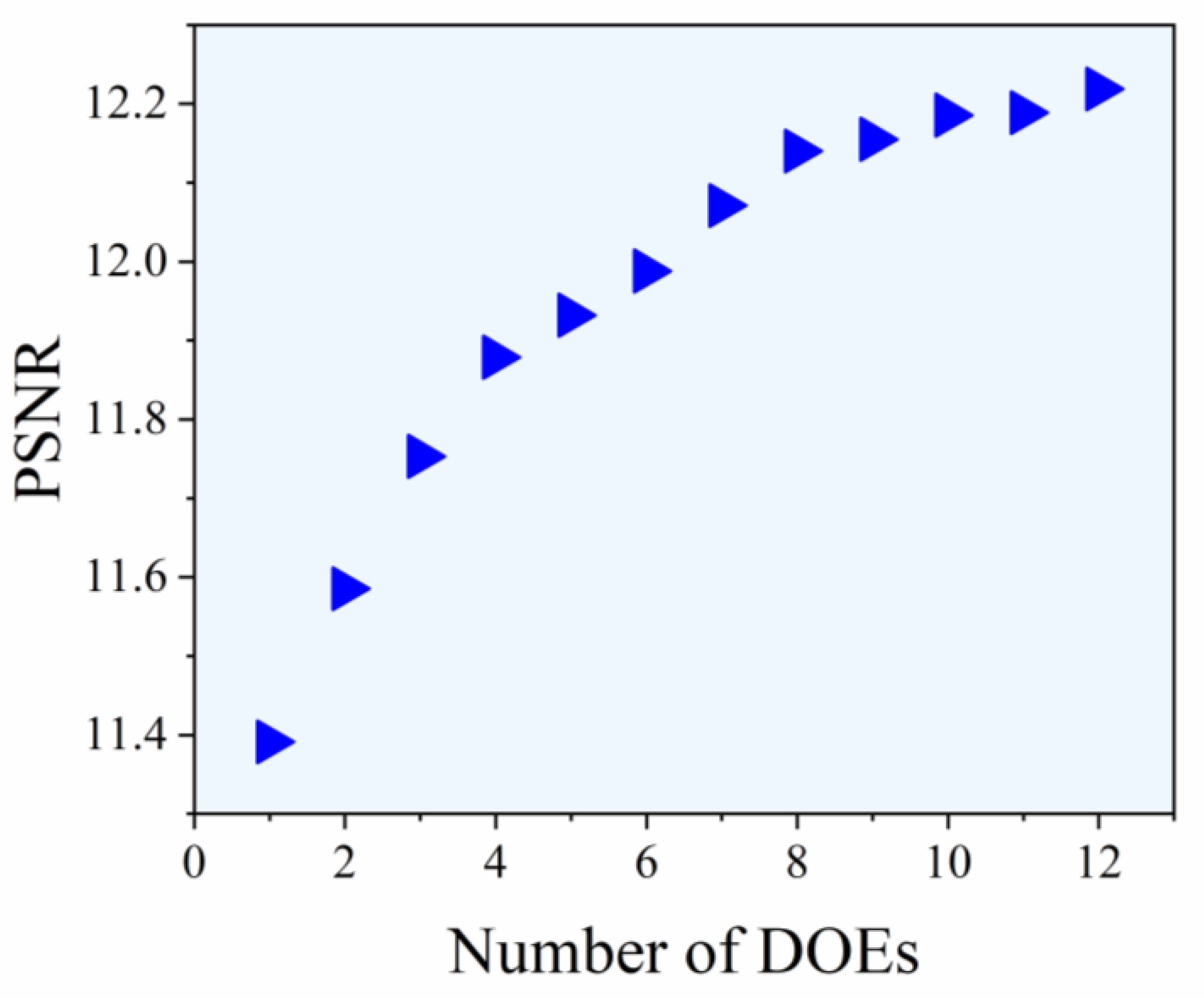
In the process of experiments, the recorded object has a rather low resolution. With the increase of the resolution of objects, the superiority of the proposed system will become more visible. Here, the relationship between the effective object points and the calculation time of the effective hologram is recorded, as shown in Figure 10, where the black triangles are the calculation time of images with different object points when using the conventional NLUT algorithm and the red circles are the ones when using the proposed system. When the number of object points is relatively small, the advantage of the proposed system is not obvious. Nevertheless, as the number of object points increases, the deviation of the calculation speed between the two algorithms becomes very obvious. It is clear that our proposed system has significant merits in the calculation of 3D objects. Speckle noise can be effectively suppressed by loading the DOEs. When we add more DOEs, we can obtain reproduced images with better quality. In Figure 11, the relationship between the number of the DOEs and PSNR is analyzed. As can be seen from the result, when the number of the DOEs increases, the PSNR increases accordingly.
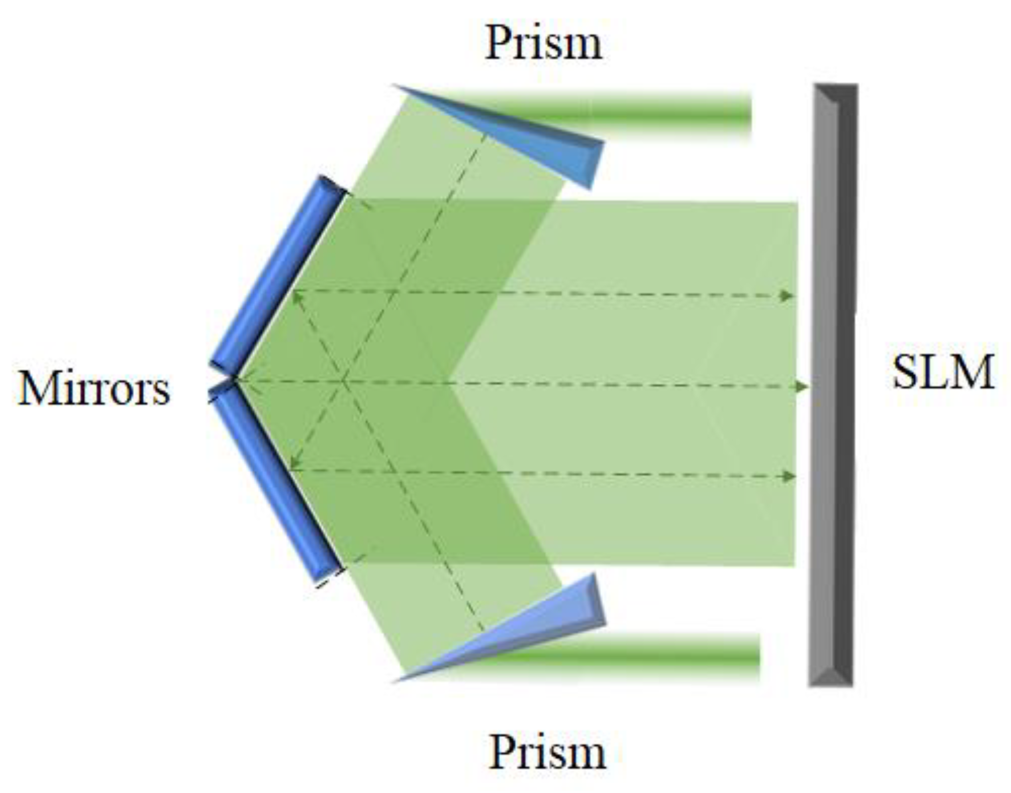
In the proposed system, two SLMs are used to suppress the speckle noise. One of the SLMs is loaded with the DOE and the other is loaded with the effective hologram. In comparison with the conventional systems, our proposed system has the advantages of fast calculation speed and reduced speckle noise. However, the system still has some problems to be solved. In the process of the hologram generation, a zero-padded operation is performed around the effective hologram. In other words, the wasted area is not being used. Ideally, we would like to utilize the wasted area and load the DOEs on it to improve the image quality. Then, only one SLM is needed to achieve the purpose of the system in this paper, as shown in Figure 12, which is the diagram of the improved system. When the collimated light travels through the iris, only a small section of the light passes through the BS and illuminates the wasted region of the SLM. DOEs are added to the wasted area of the SLM for beam shaping. Then, the “wasted light” is modulated and reflected by the SLM. After passing through the prism group, the light is expanded and re-reflected to the effective region in the SLM. The prism group in the improved system needs to have the functions of both prism expanding beam and reflection, as illustrated in Figure 13.
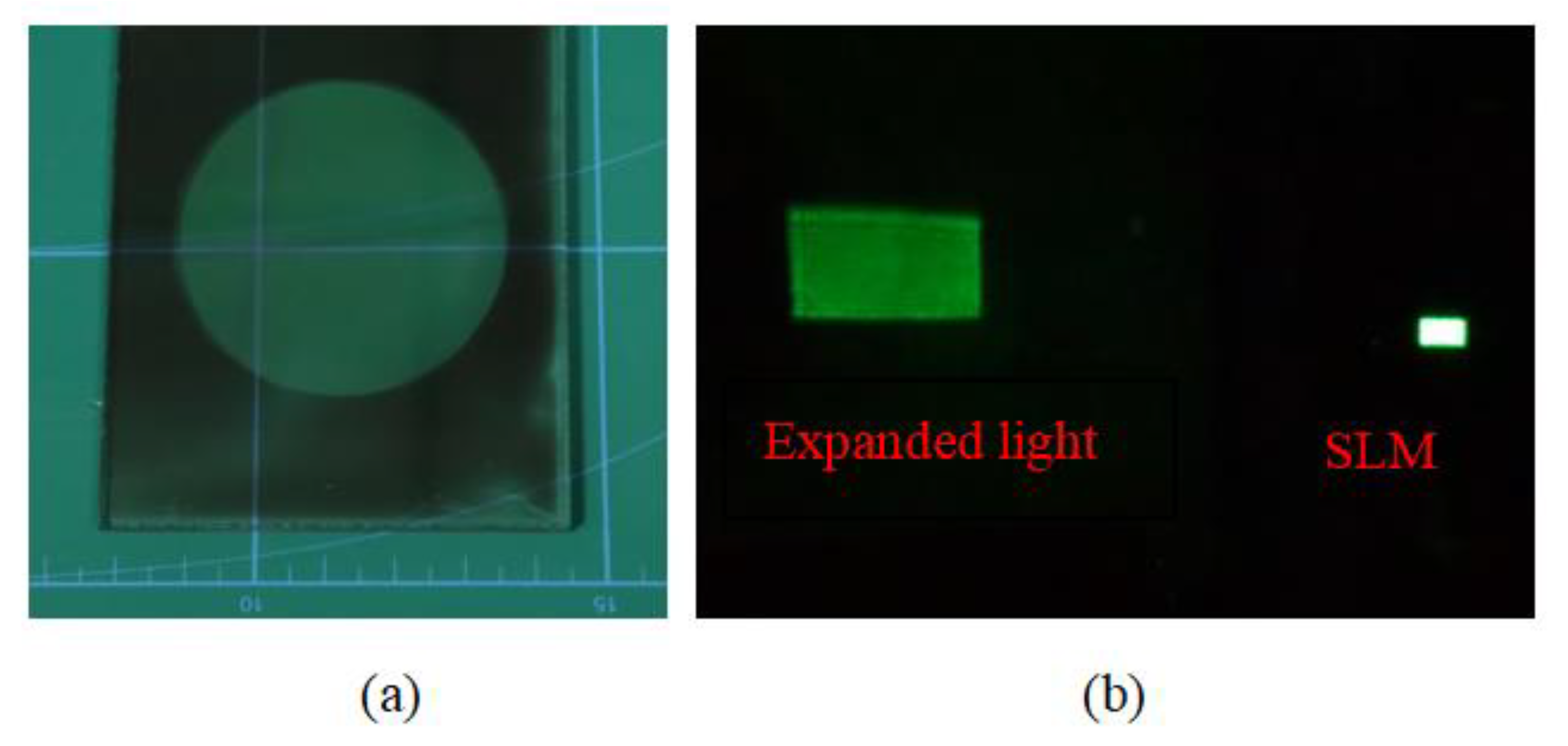
For solid prism groups, this structural design is usually complicated. If the prism group is processed into a holographic optical element (HOE), the system will be very simple. We have processed a simple prism and lens by using the HOE to achieve the beam expansion and reflection, as illustrated in Figure 14. Figure 14a shows the HOE sample, and Figure 14b shows the result of the beam expansion and reflection by using the HOE. It is clear that the zero-light of the SLM can be expanded and reflected simultaneously. Due to the limitations of our processing conditions, we have not yet been able to process more complex structures. In the future, if this process is combined with the proposed system, the system will have a larger improvement.
In the proposed system, the number of the DOE is limited by the refresh rate of the SLM, so the speckle suppression is limited. From Figure 11 we can see that the reconstructed image can have better quality when increasing the number of the DOEs. So, we can use a high-refresh SLM or other methods to increase the number of the DOEs. In the process of holographic display, the viewing position is not fixed as we imagine and it may appear in any position according to the requirement. For example, the holographic near-eye display is one of the most promising applications. If we can improve the image quality according to the position of the viewer, it will be better for the application. When further optimizing the proposed system, the results of the holographic reproduction will be better. In our next work, we will carry on advancing our research and wish to contribute to the development of holographic display.
5. Conclusions
In this paper, we propose a system to reduce the speckle noise and improve the quality of the holographic reproduced images. By calculating the effective perspective of reproduced images, the effective hologram calculated by PFP is added to the SLM. At the same time, the effective DOEs are loaded on the SLM for beam shaping. So, the system can suppress the speckle noise effectively. Besides, the calculation time is also reduced. We hope that this system can make a modest contribution to the dynamic holographic display in the future.
Author Contributions
D.W. conceived the initial idea and performed the experiments. Y.-W.Z. and N.-N.L. analyzed the data. Q.-H.W. discussed the results and supervised the project. All authors have read and approved the final manuscript.
Funding
This research was funded by National Natural Science Foundation of China under Grant No. 62020106010 and 62011540406.
Institutional Review Board Statement
Not applicable.
Informed Consent Statement
Not applicable.
Data Availability Statement
All data generated or analyzed during this study are included in this published article and its additional files.
Acknowledgments
Not applicable.
Conflicts of Interest
The authors declare no conflict of interest.
References
- Wakunami, K.; Hsieh, P.-Y.; Oi, R.; Senoh, T.; Sasaki, H.; Ichihashi, Y.; Okui, M.; Huang, Y.-P.; Yamamoto, K. Projection-type see-through holographic three-dimensional display. Nat. Commun. 2016, 7, 12954. [Google Scholar] [CrossRef] [PubMed] [Green Version]
- Yu, H.; Lee, K.; Park, J.; Park, Y. Ultrahigh-definition dynamic 3D holographic display by active control of volume speck-le fields. Nat. Photonics 2017, 11, 186–192. [Google Scholar] [CrossRef]
- Wang, D.; Liu, C.; Shen, C.; Xing, Y.; Wang, Q.-H. Holographic capture and projection system of real object based on tunable zoom lens. PhotoniX 2020, 1, 6. [Google Scholar] [CrossRef] [Green Version]
- Lee, J.S.; Kim, Y.K.; Won, Y.H. See-through display combined with holographic display and Maxwellian display using switchable holographic optical element based on liquid lens. Opt. Express 2018, 26, 19341–19355. [Google Scholar] [CrossRef]
- Deng, Z.-L.; Deng, J.; Zhuang, X.; Wang, S.; Shi, T.; Wang, G.P.; Wang, Y.; Xu, J.; Cao, Y.; Wang, X.; et al. Facile metagrating holograms with broadband and extreme angle tolerance. Light. Sci. Appl. 2018, 7, 1–8. [Google Scholar] [CrossRef] [PubMed] [Green Version]
- Sun, P.; Chang, S.Q.; Liu, S.Q.; Tao, X.; Wang, C.; Zheng, Z.R. Holographic near-eye display system based on dou-ble-convergence light Gerchberg-Saxton algorithm. Opt. Express 2018, 26, 10140–10151. [Google Scholar] [CrossRef] [PubMed]
- Wang, D.; Liu, C.; Li, L.; Zhou, X.; Wang, Q.-H. Adjustable liquid aperture to eliminate undesirable light in holographic projection. Opt. Express 2016, 24, 2098–2105. [Google Scholar] [CrossRef] [PubMed]
- Golan, L.; Shoham, S. Speckle elimination using shift-averaging in high-rate holographic display. Opt. Express 2009, 17, 1330–1339. [Google Scholar] [CrossRef] [PubMed]
- Wang, L.; Tschudi, T.; Halldórsson, T.; Pétursson, P.R. Speckle reduction in laser projection systems by diffractive optical elements. Appl. Opt. 1998, 37, 1770–1775. [Google Scholar] [CrossRef] [PubMed]
- McKechnie, T.S. Speckle reduction. In Laser Speckle and Related Phenomena; Springer: Berlin/Heidelberg, Germany, 1975; pp. 123–170. [Google Scholar]
- Amako, J.; Miura, H.; Sonehara, T. Speckle-noise reduction on kinoform reconstruction using a phase-only spatial light modulator. Appl. Opt. 1995, 34, 3165–3171. [Google Scholar] [CrossRef]
- Takaki, Y.; Yokouchi, M. Speckle-free and grayscale hologram reconstruction using time-multiplexing technique. Opt. Express 2011, 19, 7567–7579. [Google Scholar] [CrossRef]
- Yoon, Y.; Breshike, C.J.; Kendziora, C.A.; Furstenberg, R.; McGill, R.A. Reduction of speckle noise and mitigation of beam wander in tunable external cavity quantum cascade lasers using rotating diamond/KBr pellet coupled with multimode fiber. Opt. Express 2019, 27, 8011–8020. [Google Scholar] [CrossRef]
- Pang, H.; Wang, J.; Cao, A.; Deng, Q. High-accuracy method for holographic image projection with suppressed speckle noise. Opt. Express 2016, 24, 22766. [Google Scholar] [CrossRef] [PubMed]
- Ito, T.; Shimobaba, T.; Godo, H.; Horiuchi, M. Holographic reconstruction with a 10-µm pixel-pitch reflective liq-uid-crystal display by use of a light-emitting diode reference light. Opt. Lett. 2002, 27, 1406–1408. [Google Scholar] [CrossRef]
- Oikawa, M.; Shimobaba, T.; Yoda, T.; Nakayama, H.; Shiraki, A.; Masuda, N.; Ito, T. Time-division color electro holog-raphy using one-chip RGB LED and synchronizing controller. Opt. Express 2011, 19, 12008–12013. [Google Scholar] [CrossRef] [Green Version]
- Li, N.-N.; Wang, D.; Li, Y.-L.; Wang, Q.-H. Method of curved composite hologram generation with suppressed speckle noise. Opt. Express 2020, 28, 34378–34389. [Google Scholar] [CrossRef] [PubMed]
- Wang, D.; Li, N.N.; Liu, C.; Wang, Q.H. Holographic display method to suppress speckle noise based on effective utili-zation of two spatial light modulators. Opt. Express 2019, 27, 11617–11625. [Google Scholar] [CrossRef] [PubMed]
- Qi, Y.; Chang, C.; Xia, J. Speckleless holographic display by complex modulation based on double-phase method. Opt. Express 2016, 24, 30368–30378. [Google Scholar] [CrossRef] [PubMed]
- Zhao, T.; Liu, J.; Gao, Q.; He, P.; Han, Y.; Wang, Y. Accelerating computation of CGH using symmetric compressed look-up-table in color holographic display. Opt. Express 2018, 26, 16063–16073. [Google Scholar] [CrossRef]
- Shimobaba, T.; Masuda, N.; Ito, T. Simple and fast calculation algorithm for computer-generated hologram with wave-front recording plane. Opt. L. 2009, 34, 3133–3135. [Google Scholar] [CrossRef]
- Symeonidou, A.; Blinder, D.; Munteanu, A.; Schelkens, P. Computer-generated holograms by multiple wavefront record-ing plane method with occlusion culling. Opt. Express 2015, 23, 22149–22161. [Google Scholar] [CrossRef] [Green Version]
- Tsang, P.; Poon, T.-C. Fast generation of digital holograms based on warping of the wavefront recording plane. Opt. Express 2015, 23, 7667–7673. [Google Scholar] [CrossRef] [PubMed]
- Kim, S.-C.; Kim, E.-S. Effective generation of digital holograms of three-dimensional objects using a novel look-up table method. Appl. Opt. 2008, 47, D55–D62. [Google Scholar] [CrossRef]
- Kim, S.-C.; Kim, J.-M.; Kim, E.-S. Effective memory reduction of the novel look-up table with one-dimensional sub-principle fringe patterns in computer-generated holograms. Opt. Express 2012, 20, 12021–12034. [Google Scholar] [CrossRef] [PubMed]
- Kim, S.-C.; Dong, X.-B.; Kwon, M.-W.; Kim, E.-S. Fast generation of video holograms of three-dimensional moving objects using a motion compensation-based novel look-up table. Opt. Express 2013, 21, 11568–11584. [Google Scholar] [CrossRef]
- Jia, J.; Chen, J.; Yao, J.; Chu, D. A scalable diffraction-based scanning 3D colour video display as demonstrated by using tiled gratings and a vertical diffuser. Sci. Rep. 2017, 7, 44656. [Google Scholar] [CrossRef] [PubMed] [Green Version]
- Tikan, A.; Bielawski, S.; Szwaj, C.; Randoux, S.; Suret, P. Single-shot measurement of phase and amplitude by using a heterodyne time-lens system and ultrafast digital time-holography. Nat. Photon. 2018, 12, 228–234. [Google Scholar] [CrossRef]
Figure 1.
Structure of the proposed system.

Figure 2.
Principle of the effective perspective. (a) Calculation of the effective perspective; (b) calculation of the diffraction fringe pattern.
Figure 2.
Principle of the effective perspective. (a) Calculation of the effective perspective; (b) calculation of the diffraction fringe pattern.

Figure 3.
Process of the DOEs loaded on SLM1 and effective hologram loaded on SLM2.

Figure 4.
Results of the reconstructed image of “CA” without loading DOEs. (a) Result by using the traditional NLUT algorithm; (b) result by using the algorithm based on effective perspective calculation.
Figure 4.
Results of the reconstructed image of “CA” without loading DOEs. (a) Result by using the traditional NLUT algorithm; (b) result by using the algorithm based on effective perspective calculation.

Figure 5.
Simulation result of the reconstructed image. (a) Result by using the proposed system with loading DOEs; (b) result without loading the DOEs.
Figure 5.
Simulation result of the reconstructed image. (a) Result by using the proposed system with loading DOEs; (b) result without loading the DOEs.

Figure 6.
Side view of the intensities for the entire contents of Figure 5. (a) Intensity of Figure 5a; (b) intensity of Figure 5b.

Figure 7.
Optical experimental results of the reconstructed image. (a,d) Results of loading the full hologram without DOEs; (b,e) results of loading the effective hologram without DOEs; (c,f) results of loading the effective hologram with DOEs.
Figure 7.
Optical experimental results of the reconstructed image. (a,d) Results of loading the full hologram without DOEs; (b,e) results of loading the effective hologram without DOEs; (c,f) results of loading the effective hologram with DOEs.

Figure 8.
Results of the reconstructed 3D image by using the proposed system. (a) Result when “H” is focused; (b) result when “B” is focused.
Figure 8.
Results of the reconstructed 3D image by using the proposed system. (a) Result when “H” is focused; (b) result when “B” is focused.

Figure 9.
Results of the reconstructed image by using the proposed system based on the GS algorithm. (a) Result of loading the hologram without DOEs; (b) result of loading the hologram with DOEs.
Figure 9.
Results of the reconstructed image by using the proposed system based on the GS algorithm. (a) Result of loading the hologram without DOEs; (b) result of loading the hologram with DOEs.

Figure 10.
Relationship between the calculation time of the hologram and the object points by using different algorithms.
Figure 10.
Relationship between the calculation time of the hologram and the object points by using different algorithms.

Figure 11.
Relationship between the number of the DOEs and PSNR by using the proposed system.

Figure 12.
Diagram of the improved system by using one SLM.

Figure 13.
Principle and structure of the prism group.

Figure 14.
Results of the HOE. (a) HOE sample; (b) result of the beam expansion and reflection by using the HOE.
Figure 14.
Results of the HOE. (a) HOE sample; (b) result of the beam expansion and reflection by using the HOE.

Publisher’s Note: MDPI stays neutral with regard to jurisdictional claims in published maps and institutional affiliations. |
© 2021 by the authors. Licensee MDPI, Basel, Switzerland. This article is an open access article distributed under the terms and conditions of the Creative Commons Attribution (CC BY) license (https://creativecommons.org/licenses/by/4.0/).
Share and Cite
MDPI and ACS Style
Wang, D.; Zheng, Y.-W.; Li, N.-N.; Wang, Q.-H. Holographic Display System to Suppress Speckle Noise Based on Beam Shaping. Photonics 2021, 8, 204. https://doi.org/10.3390/photonics8060204
AMA Style
Wang D, Zheng Y-W, Li N-N, Wang Q-H. Holographic Display System to Suppress Speckle Noise Based on Beam Shaping. Photonics. 2021; 8(6):204. https://doi.org/10.3390/photonics8060204
Chicago/Turabian StyleWang, Di, Yi-Wei Zheng, Nan-Nan Li, and Qiong-Hua Wang. 2021. "Holographic Display System to Suppress Speckle Noise Based on Beam Shaping" Photonics 8, no. 6: 204. https://doi.org/10.3390/photonics8060204
Note that from the first issue of 2016, this journal uses article numbers instead of page numbers. See further details here.