Geometric Representation of Vector Vortex Beams: The Total Angular Momentum-Conserving Poincaré Sphere and Its Braid Clusters

1
School of Electronics & Computer Science, University of Southampton, Southampton SO17 1BJ, UK
2
School of Mathematical Sciences, University of Southampton, Southampton SO17 1BJ, UK
*
Author to whom correspondence should be addressed.
Photonics 2023, 10(11), 1276; https://doi.org/10.3390/photonics10111276
Submission received: 17 August 2023
/
Revised: 12 November 2023
/
Accepted: 13 November 2023
/
Published: 17 November 2023
(This article belongs to the Special Issue Exploring the Potential of Opto-Mechanics and Spin-Mechanics for Quantum Technologies)
Abstract
:This paper presents the total angular momentum-conserving Poincaré sphere (TAM-C PS), which offers a novel framework for efficiently characterizing a wide range of vector vortex beams. Unlike other types of Poincaré spheres, the TAM-C PS achieves a better balance between generality and validity, while also providing clearer physical interpretation. By linking the poles of different spheres, the study also introduces two distinct categories of TAM-C PS braid clusters, enabling the representation of various Poincaré spheres within a unified framework. The Poincaré spheres include classical, higher-order, hybrid-order, Poincaré sphere with orbital angular momentum, and TAM-C PS. This is the first clear and unified approach to express multiple Poincaré spheres within a single framework. The TAM-C PS and its braid cluster can be employed to guide the creation of targeted vector vortex light beams, offer a geometric description of optical field evolution, and calculate the geometric phase of optical cyclic evolution.
1. Introduction
Light is composed of many photons that are absorbed and emitted by atomic systems as electromagnetic radiation. This property classifies light as an electromagnetic wave [1]. An electromagnetic wave can be defined and described by a vector field, which contains two degrees of freedom: spatial degrees of freedom (DoF) and polarization DoF [2]. In recent years, both DoFs have garnered significant attention and have been studied and applied in various fields. For instance, polarization DoF have found applications in tight focusing of light beams [3], particle acceleration [4], vectorial Doppler metrology for detecting universal motion vectors [5], nonlinear optics [6], and classical entanglement [7]. The spatial DoF of light can be controlled manipulating the orbital angular momentum (OAM). This has led to what we now refer to as structured light [8]. Structured light has been applied in areas such as imaging and microscopy [9], optical trapping [10,11], and quantum computing [12], to name a few. By controlling these two DoFs of light, we can generate a variety of more complex optical fields. A concise method to characterize and describe these complex optical fields is highly desired. The Poincaré sphere is a powerful and practical tool, providing a descriptive framework for these intricate light fields, characterizing their physical properties, and finding broad applications in engineering.
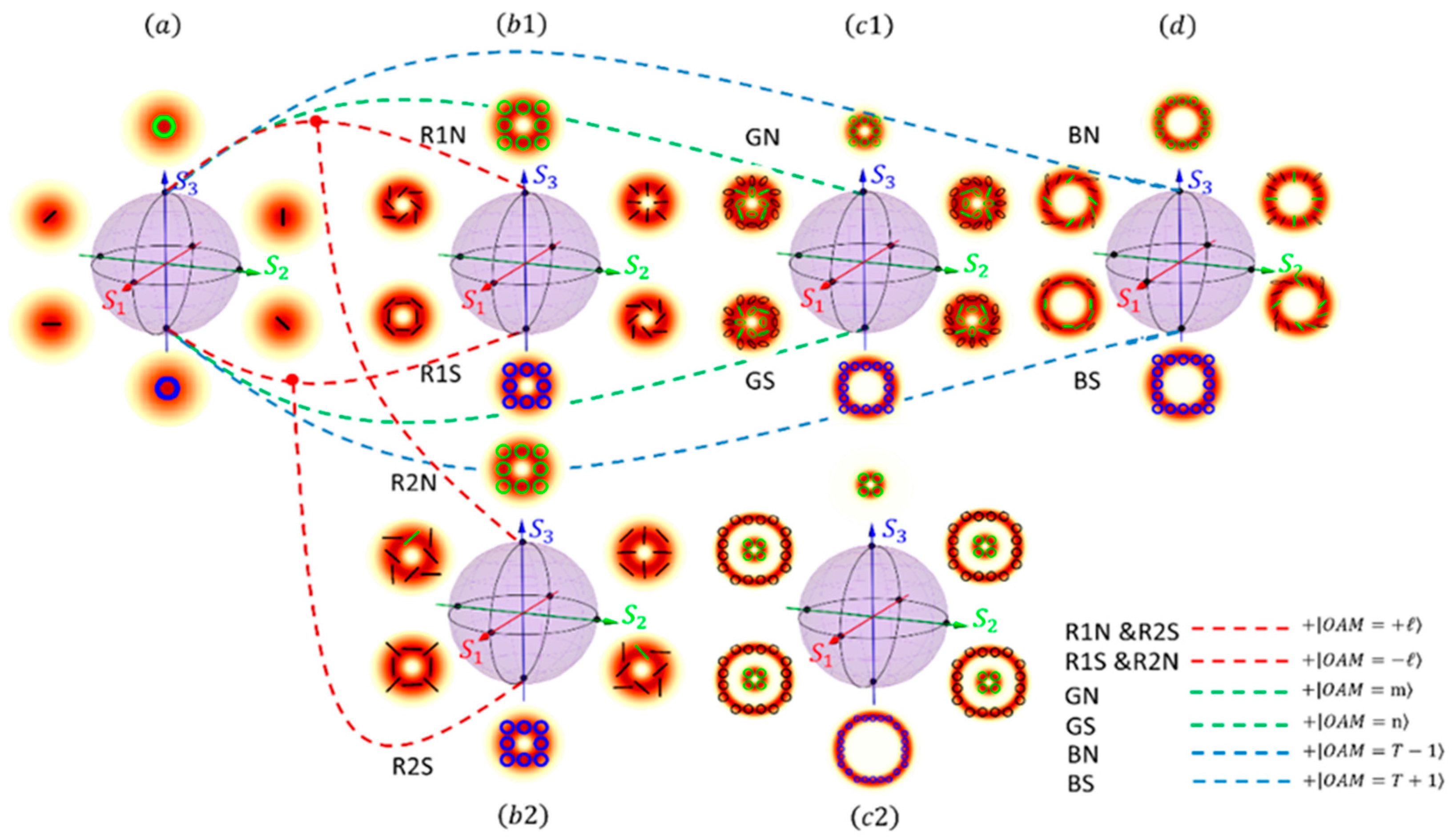
Several Poincaré spheres have been proposed and investigated. The development process of Poincaré spheres is illustrated in Figure 1, with Figure 1a–d depicting classical Poincaré sphere (Classical-PS), higher-order Poincaré sphere (HOPS), hybrid-order Poincaré sphere (HyOPS), and total angular momentum-conserving Poincaré sphere (TAM-C PS), respectively. The dashed lines connecting the spheres signify the evolutionary changes in the definitions of each generation of Poincaré spheres, relative to the Classical-PS.
The Classical-PS was introduced in 1892 as a representation within the optical context of Bloch spheres. Various polarization states of optical fields can be clearly characterized on it [13]. Its north and south poles are defined as left and right circular polarizations, which form an orthogonal basis. Any other pure state field can be constructed through complex linear combinations of these two basis vectors. This implies that four real numbers are needed to describe such a pure state field. However, only the relative phase between the two orthogonal bases has physical significance. Therefore, three real numbers are sufficient to characterize any pure state field, leading to the construction of a three-dimensional Poincaré sphere. The relative phases of the orthogonal bases are represented by two angles, and , which are mapped to the polar and azimuthal angles of the Poincaré sphere, respectively. Further mathematical details are provided in Section 2 and Section 3. Consequently, different polarization states of light beams can be mapped onto the Poincaré sphere, and it provides a geometric model that offers an intuitive and insightful representation framework for complex light field polarizations, leading to widespread applications [14].
However, the Classical-PS cannot describe higher-order solutions of Maxwell’s vector wave equation. In 2011, Giovanni et al. developed a new type of Poincaré sphere called the HOPS by extending the complex Jones vector basis of plane-wave polarization [15]; Unlike the eigenmodes corresponding to the two poles of the Classical-PS, the HOPS introduces orbital states of equal magnitude but opposite handedness in its expressions. It should be noted that different OAM states are orthogonal to each other, making OAM states a complete orthogonal basis, allowing any optical field to be decomposed on this basis. Therefore, the introduction of OAM still ensures the orthogonality of the eigenmodes. In this way, the introduction of spatial degrees of freedom is achieved, and a special type of light beam, the cylindrical vector beam, can be characterized within the framework of the Poincaré sphere. However, the HOPS does not incorporate an important type of light beam, vector vortex beams, into the Poincaré sphere framework. The Figure 1(b1,b2) illustrate the concept of the HOPS, where the red dashed lines represent the extension of the definition of HOPS eigenmodes relative to that of the Classical-PS. It is worth noting that there are two types of HOPSs. This is due to the fact that the handedness of OAM can be the same or opposite to that of circular polarization (it corresponds to spin angular momentum (SAM) ). The Figure 1(b1) represents the case where the handedness is the same, while the Figure 1(b2) represents the opposite handedness cases.
In 2015, Yi et al. introduced the HyOPS, which shares a similar construction with the HOPS [16]; Unlike the HOPS, the HyOPS allows arbitrary selection of the state value and sign of OAM. The green dashed lines in Figure 1 illustrate this modified definition. This makes the HyOPS a more generalized Poincaré sphere, capable of expressing vector vortex beams. However, it should be noted that some HyOPSs are ill-defined. This issue arises from the geometric mismatch of their eigenmodes, which leads to a contradiction: the optical fields generated based on the definition of eigenstates by HyOPSs sometimes do not satisfy the definition of Stokes parameters, as shown in the Figure 1(c2). It can be observed that the radii of the eigenmodes corresponding to the two poles of the sphere are significantly different. Because the beam radius (defined at the point of maximum intensity, relative to the beam center) is directly proportional to the magnitude of the topological charge, (corresponding to the modulus of the OAM eigenvalue), i.e., . Therefore, the geometric size of beams carrying different OAM values will differ, especially when there is a substantial difference between the topological charge values carried by the two eigenmodes. This significant size mismatch in the eigenstates results in the outcome shown in the Figure 1(c2) which is inconsistent with the definition of Stokes parameters.
Based on the research and analysis of the existing Poincaré sphere systems, this study proposes a new Poincaré sphere theoretical framework that not only inherits the characteristics of previous generations but also overcomes the limitations of the current Poincaré spheres. Building upon previous work, we introduce a condition based on the conservation of total angular momentum (TAM) and define a new Poincaré sphere, which we refer to as the TAM-C PS. The Figure 1d provides a schematic illustration of TAM-C PS. Due to its incorporation of the concept of angular momentum conservation, TAM-C PS provides a clearer physical interpretation and depiction compared to existing Poincaré spheres. Considering the complexity and limited applicability of classical and existing higher-order Poincaré spheres, as well as the issues with certain definitions, TAM-C PS emerges as a valuable addition to this field. Furthermore, based on TAM-C PS, this study introduces two TAM-C PS braid clusters, which enable the characterization of various Poincaré spheres, including the Classical-PS, HOPS, HyOPS, and Poincaré sphere with orbital angular momentum (PS-OAM), within a single framework.
A brief overview of the development process of Poincaré spheres is provided with Figure 1a–d in depicting Classical-PS, HOPS, HyOPS, and TAM-C PS, respectively. The dashed lines connecting the spheres represent the evolutionary progression of the definition of each generation of Poincaré spheres relative to the Classical-PS. Two key points should be noted:
a. The HOPS has two types, as shown in Figure 1(b1,b2). The Figure 1(b1) illustrates the case where the handedness of OAM and SAM is identical, whereas the Figure 1(b2) depicts the scenario where their handedness are opposite. Consequently, the polarizations of the optical fields represented by the spheres in Figure 1(b1,b2) are different.
2. Methods
2.1. Total Angular Momentum of Monochromatic Paraxial Beams
This study integrates the conservation conditions of total angular momentum (TAM) into the higher-order Poincaré sphere system, establishing a novel framework for representing vector vortex beams. In this section, we elucidate the concept of TAM conservation and explain how it functions within the Poincaré sphere to give rise to the new total angular momentum-conserving Poincaré sphere (TAM-C PS) introduced in this paper. It is important to note that all beams discussed in this study are considered under the assumption of monochromatic paraxial approximation. This refers to a class of well-collimated beams in which all light rays form only slight angles with the beam axis. Within this context, the quantum number for TAM can be expressed as the sum of the quantum numbers for spin angular momentum (SAM: ) and orbital angular momentum (OAM: ) [17]. However, it is important to clarify that the magnitude of the TAM cannot always be straightforwardly defined as the sum of the magnitudes of SAM and OAM [18]. Nevertheless, for monochromatic paraxial light beams, these two inherently different forms of angular momenta can be well-distinguished: SAM is defined by the dynamic rotation of electric and magnetic fields around the direction of propagation and is described by a characteristic phase factor , where is the spin quantum number, given values of or ; OAM is defined by the dynamic rotation of light rays around the central axis of the beam and is described by a characteristic phase factor , where is the topological charge number, given values of or any integer. It is worth noting that SAM and OAM are related to circular polarization of the electric field and the helical wavefront of the beam [19], respectively, in the case of paraxial beams. Furthermore, both azimuthal angles and are defined in the transverse plane orthogonal to the direction of light propagation (e.g., -direction), with their values ranging from [0, 2π). Thus, the definitions of these two azimuthal angles are equivalent, allowing the phase factor of monochromatic paraxial light beams carrying both SAM and OAM to be expressed as . Consequently, the value of TAM, under the assumption of monochromatic paraxial approximation, is given by per photon.
This conclusion can also be verified using group theory, where infinitesimal operators provide the starting point for defining the corresponding groups. SAM and OAM characterize the intrinsic polarization degrees of freedom and the orbital degrees of freedom, respectively [20]. Since these two quantities are generated in different spaces, their commutation relation can be expressed as [21]
When operators and act together on one system, the corresponding action of the infinitesimal rotation can be expressed as
Then, the TAM can be defined as
The of in Equation (3) represents a unit position operator in orbital space, and that of represents a unit operator in spin space. Equation (3) can be expressed in a more concise form as
J ≡ S + L.
In this work, all light beams are discussed under the assumption of monochromatic paraxial approximation. Consequently, the value of TAM of each TAM-C PS is equal to .
The aim of this work is to integrate the conservation conditions of TAM into the higher-order Poincaré sphere system. More specifically, each TAM-C PS represents a rotationally symmetric system. In contrast to other Poincaré spheres, our framework specifically constrains the magnitude of TAM for light beams on a TAM-C PS to a designated value. As a result, the evolution path of optical fields within the same sphere is characterized by TAM conservation, and the entire physical system displays rotational symmetry. For systems where angular momentum is not conserved, two or even multiple spheres can be employed to represent the process of TAM non-conservation. The mathematical definition of TAM-C PS will be provided subsequently, and we will elaborate in detail how this definition satisfies the condition that the TAM of a beam represented on the same sphere is of a specific value.
2.2. Total Angular Momentum-Conserving Poincaré Sphere Representation
In this part, we introduce the mathematical definition of the TAM-C PS. An arbitrary pure state can be constructed through the complex linear combination of two eigenstates, represented as the north and south poles on the Poincaré sphere. Accordingly, the mathematical expression for a monochromatic paraxial beam corresponding to a point on the TAM-C PS is formulated as follows:
We use the notation to represent a monochromatic paraxial beam corresponding to a point with TAM on the TAM-C PS. The symbols and represent a pair of eigenstates located on the north and south poles of the TAM-C PS, respectively. Specifically, these eigenstates represent right-circularly and left-circularly polarized vortex beams with OAM quantified as , , respectively. The symbols , represent the coefficients of these two eigenstates, which are defined by relative intensity (variables ) and relative phase ().
Based on the requirement of TAM conservation, the TAM (denoted as ) of light beams corresponding to points on the same spherical surface should be the same. The polarization state at the north pole is designated as right-handed circular polarization (), while the state at the south pole is established as left-handed circular polarization (). As a result, the topological charge of the OAM at the north pole is , and at the south pole, it is ; the OAM at the south pole is greater than that at the north pole by 2.
By defining the Stokes parameters, we can geometrically project arbitrary pure states, as represented by Equation (5), onto the TAM-C PS. The Stokes parameters for the TAM-C PS are specified as outlined in Equations (6)–(9) [22]:
The parameter represents the normalized optical field intensity, and it is reflected in TAM-C PS as sphere’s radius. By examining the expressions for , and (Equations (7)–(9)), we can see that these three parameters are precisely the expressions for the unit sphere coordinates. Therefore, using the parameters , and , we define three mutually orthogonal axes for TAM-C PS. Subsequently, any pure state field can be mapped onto a sphere.
3. Results
3.1. The Total Angular Momentum-Conserving Poincaré Sphere and Its Properties
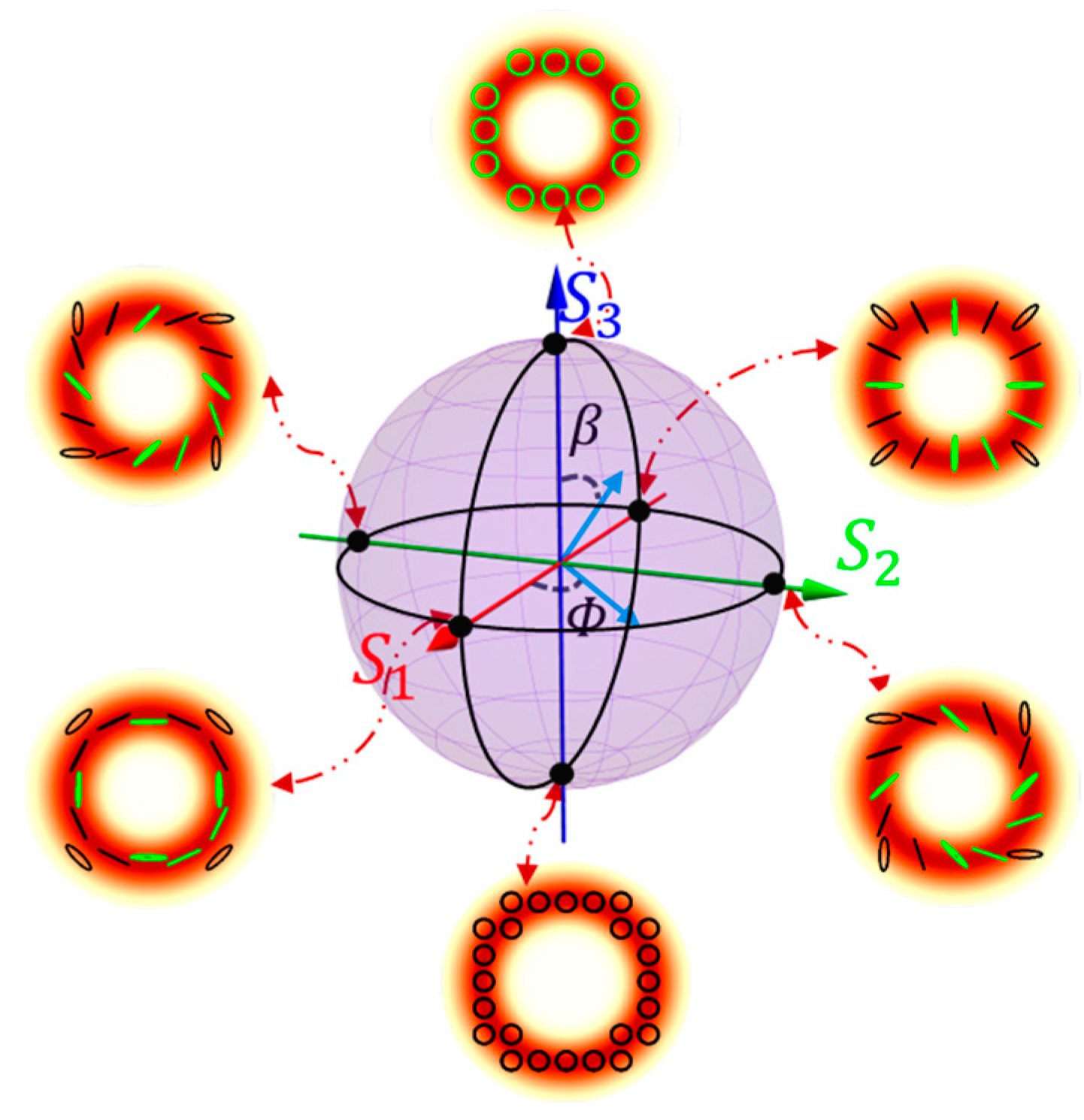
In Section 2, we defined the Stokes parameters of the TAM-C PS. With the help of S1, S2, and S3, we can establish a three-dimensional coordinate, as well as a TAM-C PS with TAM , as shown in Figure 2. The intensity and polarization distributions of pure states in all figures are the results of numerical calculations performed using MATLAB. The axes colored in red, green, and blue correspond to S1, S2, and S3, respectively; the sphere’s radius is defined by S0. Additionally, Figure 2 displays intensity and polarization distribution of four types of beams. These beams are represented by two pairs of antipodal points on the sphere’s equator. Variations in intensity are illustrated through gradations in color, while the polarization attributes of the fields are conveyed by the form and orientation of lines. Because of the conservation of TAM, for the sphere depicted in Figure 2, eigenmodes corresponding to its north pole () have SAM and OAM values of , , respectively, while those corresponding to its south pole () have SAM and OAM values of and , respectively.
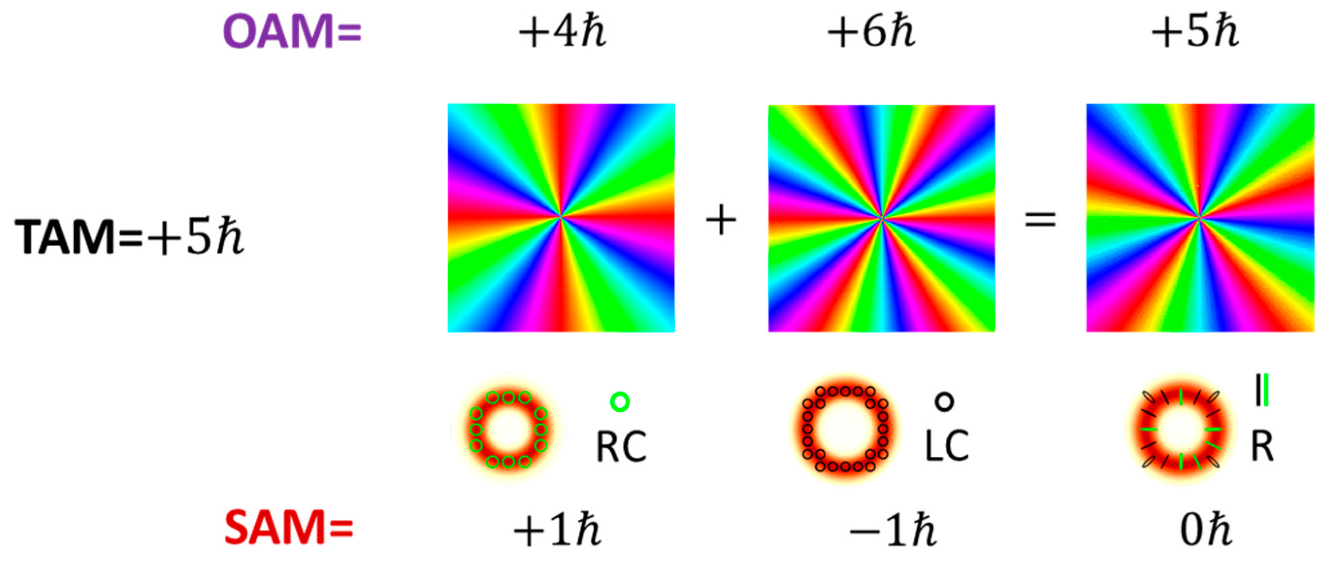
According to Equation (5), vector vortex beams represented by points on the equator () exhibit cylindrical polarization characteristics that has SAM = and OAM = . Additionally, points not on the two poles and equator correspond to elliptically polarized vortex beams with TAM = . This is a direct consequence of TAM conservation. Using MATLAB, we computed the wavefront phase, intensity, and polarization distribution of a specific equatorial light field represented by TAM-C PS through the superposition of eigenstates, as shown in Figure 3.
From Figure 3, we can observe that the wavefront phase of the resulting beam repeats five times, indicating that the beam possesses an OAM with a magnitude of . The calculated result matches the prediction of OAM = based on Equation (5). At the bottom of Figure 3, the red doughnut shape represents the intensity distribution, and the green and black lines indicate the polarization state of the resulting beam which match our expected radial polarization state.
3.2. Total Angular Momentum-Conserving Poincaré Sphere Clusters
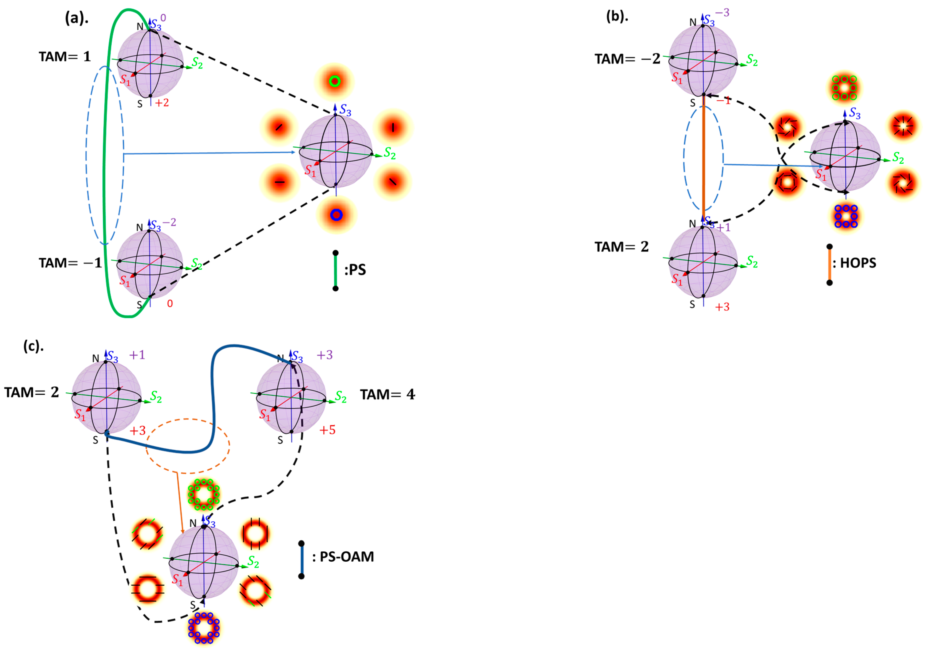
This part presents the construction and properties of TAM-C PS braid clusters. Noether’s theorem states that each conservation law corresponds to a fundamental symmetry (invariance) within the field of physics, with the conservation of angular momentum being associated with rotational symmetry in systems [23]. This implies that each TAM-C PS we construct inherently represents a rotationally symmetric system. By connecting spheres with different TAM values, we can describe the non-conservation of TAM or non-rotationally symmetric systems. This inspires the idea of using two TAM-C PSs to represent Classical-PS, HOPS, and PS-OAM spheres. Figure 4 shows how Classical-PS, HOPS, and PS-OAM can be represented by two TAM-C PSs.
Based on the definitions and properties of the existing Poincaré spheres: the Classical-PS has no OAM DoF, the HOPS requires opposite-signed OAM at its two poles, and the PS-OAM requires identical OAM at its two poles. We can redefine them by connecting the north pole of one TAM-C PS to the south pole of another, thereby establishing a new set of poles. This approach allows for the characterization of the Classical-PS, HOPS, and PS-OAM within the framework of the TAM-C PS, as illustrated in Figure 4. It is important to note that the HyOPS does not need to be reconstructed because all Poincaré spheres discussed in this paper fall under the category of the HyOPS. Based on these conclusions, we constructed a braid cluster that can contain the Poincaré spheres mentioned in this study. Figure 5a,b show two types of braid clusters. Because there are two categories of the HOPS due to their different pole definitions (as explained in the Introduction), to comprehensively cover all possible cases, we constructed these two clusters.
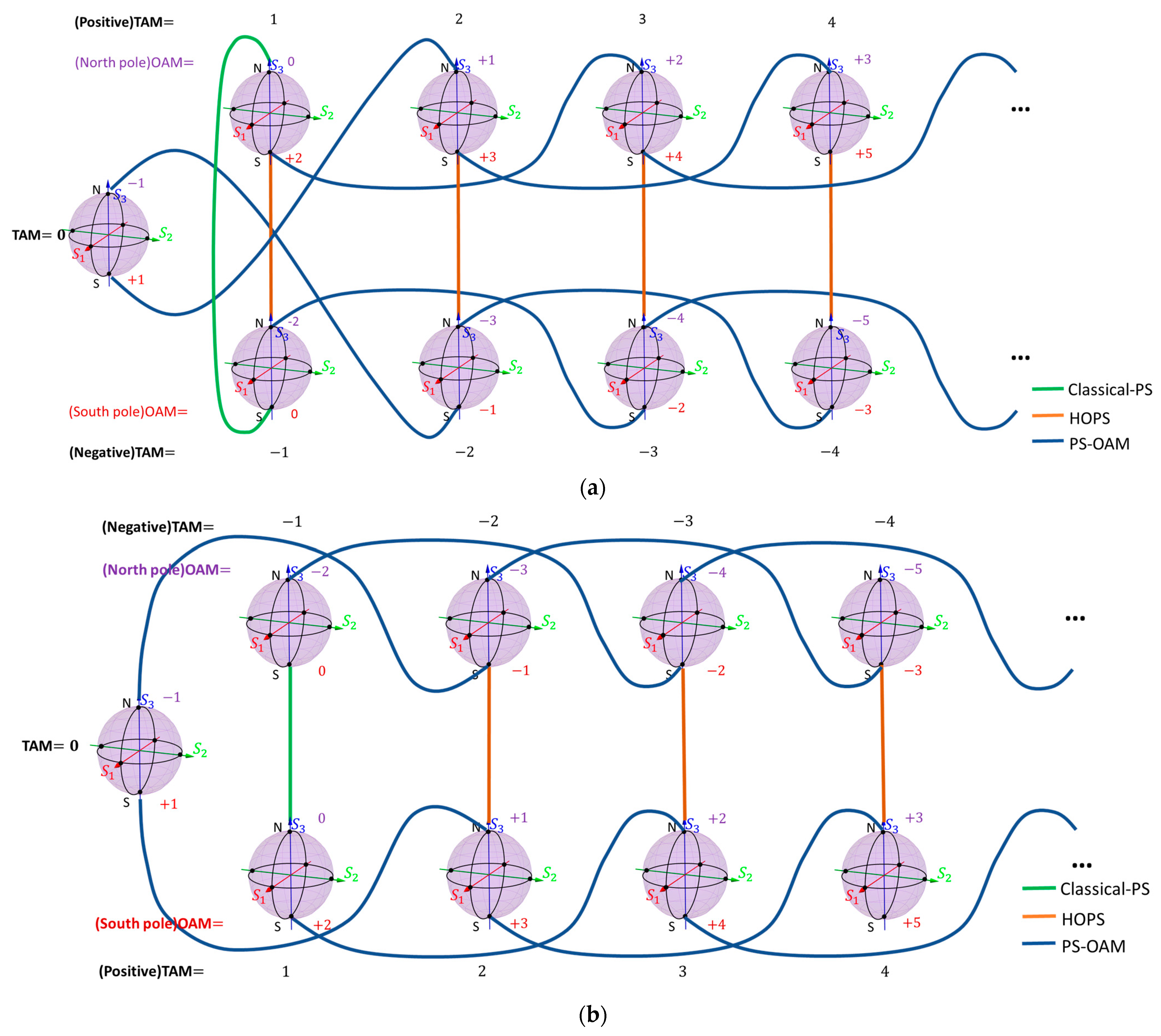
The values of the TAM can be divided into three types: TAM , and . Therefore, we classify the TAM-C PS into three types. The arrangement of these three types of spheres is shown in Figure 5.
Figure 5a,b illustrate two types of TAM-C PS braid clusters. In Figure 5a, the spheres with TAM are placed at the top of the image; spheres with TAM are positioned at the bottom, and spheres with TAM are placed slightly to the left in the middle of the two types of spheres. In contrast, in Figure 5b, the second type of cluster inverts the relative positions of spheres with TAM and TAM . The green, orange, and dark blue lines in the figure represent the Classical-PS, HOPS, and PS-OAM, respectively.
4. Discussion
In this section, we will discuss some important features of the TAM-C PS and its braid clusters.
On one TAM-C PS, the OAM of the beam represented by its north pole is always less than that of the beam represented by its south pole.
In Figure 5a, all the HOPSs belong to the second category. Notably, the TAM-C PS with TAM is equivalent to the HOPS with poles carrying OAM.
In Figure 5b, nearly all HOPSs belong to the first category, except for the TAM-C PS with TAM (which, as mentioned in the last point, is equivalent to the second category of HOPSs with poles carrying OAM).
The PS-OAM is constructed by linking the north pole of one TAM-C PS with the south pole of another sphere, both having the same OAM value. This implies that the orbital states of the two eigenmodes represented by the north and south poles of the PS-OAM are not orthogonal. Despite the non-orthogonality of the orbital states, the polarization states of the two poles remain orthogonal to each other. Therefore, the PS-OAM can be considered as a special type of Classical-PS with a specific OAM state.
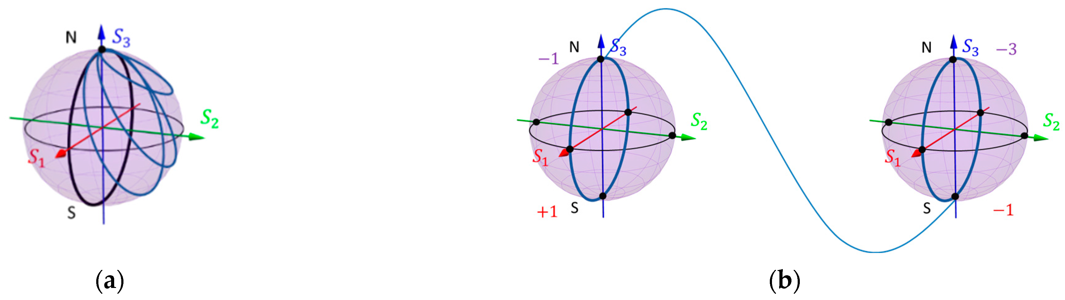
Figure 6 illustrates two types of light beam evolution paths within the braid clusters. In the Figure 6a, the black line depicts a closed path starting from the north pole, passing through the south pole, and returning to the north pole. This closed path can be further reduced to the collection of blue lines and eventually to a single point. In contrast, the solid line linking two spheres in the Figure 6b cannot be reduced to a single point like the closed curve in the Figure 6a. Inspired by this geometric property, we attempt to find its corresponding physical significance. These two types of paths represent two distinct evolution processes. The first type (shown in the Figure 6a) corresponds to the TAM conservation process of a rotationally symmetric system, as the entire optical field evolution process occurs on the same TAM-C PS. Through calculation, it can be shown that the geometric phase associated with this cyclic evolution process is always zero (details of the calculation are presented below). In contrast, the second type of optical field evolution path represents the TAM non-conservation process, corresponding to a rotationally symmetric breaking system, and the geometric phase generated by this process is generally non-zero.
When a pure state undergoes a cyclic optical evolution within the parameter space , returning to its initial state, an additional phase (geometric phase) emerges in addition to the dynamic phase. This geometric phase is described by the equation [24,25]:
is the Berry curvature, defined as:
is named the Berry connection, as given in [25]:
represents the pure state on the TAM-C PS. It is expressed as:
Notations and denote the polar and azimuthal angles of the Poincaré sphere, respectively. The Berry connection has three components in spherical coordinates, which are , , and . By substituting Equation (13) into Equation (12), the expressions of these three components can be obtained, and they are shown as follows:
Therefore, by substituting Equation (14) into Equation (11), we can get the Berry curvature
Consequently, by substituting the Berry curvature into Equation (10), the geometric phase can be got
Here, Ω represents the surface area enclosed by the circuit on the TAM-C PS. This equation illustrates that the geometric phase is directly proportional to the variation in . Because equals 0 on the same TAM-C PS (this property has been discussed in the method), both the Berry curvature and the geometric phase become null.
In terms of the breadth of the definitions, the HyOPS represents the most generalized form of Poincaré spheres. However, despite this, the HyOPS itself has some limitations: it contains some poorly defined cases (as detailed in the introduction), and due to its overly generalized nature, it combines various Poincaré spheres into a single entity, obscuring the distinct characteristics and application premises of individual Poincaré spheres, making it challenging for users to intuitively grasp their differences. Hence, the TAM-C PSs can be regarded as an effective classification method for the HyOPS family. This approach not only filters out poorly defined HyOPS but also provides a concise and intuitive way, i.e., TAM-C PS braid cluster to characterize relationships among different Poincaré spheres. And these braid clusters can help us identify the topological symmetries of a given system and determine the relationships between light fields within the system or between them and light fields in other systems. Consequently, this cluster can be used to geometrically describe the evolution of various vector vortex beams. The TAM-C PSs serve as powerful and useful tools in optical research and engineering.
5. Conclusions
This study introduces the concept of the conservation of total angular momentum within the framework of the Poincaré sphere, leading to a new type of Poincaré sphere known as the total angular momentum-conserving Poincaré sphere (TAM-C PS). By linking the poles of different TAM-C PSs, we create two categories of TAM-C PS braid clusters. Vector vortex beams have been widely applied in the field of opto-mechanics: enhancing the stability of particle trapping; simultaneously detecting the velocity and direction of particle motion; and manipulating particles beyond three-dimensional (3D) spatial manipulation. The TAM-C PS and its braid cluster offer a comprehensive framework for the representation and characterization of these beams, and they can serve as a guide to generate the targeted vector vortex light beams as well.
Compared to other types of Poincaré spheres, the TAM-C PS achieves a more balanced compromise between generality and practical application.
The TAM-C PS braid clusters include various types of Poincaré spheres, such as the classical, higher-order, hybrid-order, and Poincaré sphere with orbital angular momentum. This approach provides an intuitive and clear representation of the relationships between these different types of spheres. The braid cluster methodology holds significant practical value, including geometrically describing the evolution of optical fields, and calculating the geometric phase for cyclic evolution. The TAM-C PS and its associated braid clusters contribute valuable insights to the field of optics.
Author Contributions
Conceptualization, W.Y., H.P. and J.Y.; methodology, W.Y.; software, W.Y.; validation, W.Y., H.P., J.Y. and M.T.; formal analysis, W.Y.; investigation, W.Y. and H.P.; resources, J.Y.; data curation, W.Y.; writing—original draft preparation, W.Y.; writing—review and editing, J.Y., H.P. and M.T.; supervision, J.Y. All authors have read and agreed to the published version of the manuscript.
Funding
This research was funded by the Engineering and Physical Sciences Research Council EP/V000624/1.
Institutional Review Board Statement
The authors declare that they have NO affiliations with or involvement in any organization or entity with any financial interest in the subject matter or materials discussed in this manuscript.
Informed Consent Statement
Not applicable.
Data Availability Statement
The data that support the findings of this study are available upon reasonable request from the authors.
Conflicts of Interest
The authors declare no conflict of interest.
References
- Yoshida, S. Light as EM Wave. In Fundamentals of Optical Waves and Lasers; Springer International Publishing: Cham, Switzerland, 2023; pp. 35–66. [Google Scholar]
- Bliokh, K.Y.; Rodríguez-Fortuño, F.J.; Nori, F.; Zayats, A.V. Spin–orbit interactions of light. Na. Photonics 2015, 9, 796–808. [Google Scholar] [CrossRef]
- Liu, S.; Guo, Z.; Li, P.; Wei, B.; Zhao, J. Tightly autofocusing beams: An effective enhancement of longitudinally polarized fields. Opt. Lett. 2020, 45, 575–578. [Google Scholar] [CrossRef]
- Kimura, W.D.; Kim, G.H.; Romea, R.D.; Steinhauer, L.C.; Pogorelsky, I.V.; Kusche, K.P.; Fernow, R.C.; Wang, X.; Liu, Y. Laser acceleration of relativistic electrons using the inverse Cherenkov effect. Phys. Rev. Lett. 1995, 74, 546. [Google Scholar] [CrossRef] [PubMed]
- Fang, L.; Wan, Z.; Forbes, A.; Wang, J. Vectorial doppler metrology. Nat. Commun. 2021, 12, 4186. [Google Scholar] [CrossRef] [PubMed]
- Bouhelier, A.; Beversluis, M.; Hartschuh, A.; Novotny, L. Near-field second-harmonic generation induced by local field enhancement. Phys. Rev. Lett. 2003, 90, 013903. [Google Scholar] [CrossRef] [PubMed]
- Töppel, F.; Aiello, A.; Marquardt, C.; Giacobino, E.; Leuchs, G. Classical entanglement in polarization metrology. New J. Phys. 2014, 16, 073019. [Google Scholar] [CrossRef]
- Rubinsztein-Dunlop, H.; Forbes, A.; Berry, M.V.; Dennis, M.R.; Andrews, D.L.; Mansuripur, M.; Denz, C.; Alpmann, C.; Banzer, P.; Bauer, T.; et al. Roadmap on structured light. J. Opt. 2016, 19, 013001. [Google Scholar] [CrossRef]
- Ritsch-Marte, M. Orbital angular momentum light in microscopy. Philos. Trans. R. Soc. A Math. Phys. Eng. Sci. 2017, 375, 20150437. [Google Scholar] [CrossRef] [PubMed]
- Jesacher, A.; Fürhapter, S.; Bernet, S.; Ritsch-Marte, M. Size selective trapping with optical “cogwheel” tweezers. Opt. Express 2004, 12, 4129–4135. [Google Scholar] [CrossRef] [PubMed]
- Yang, Y.; Ren, Y.X.; Chen, M.; Arita, Y.; Rosales-Guzmán, C. Optical trapping with structured light: A review. Adv. Photonics 2021, 3, 034001. [Google Scholar] [CrossRef]
- Goyal, S.K.; Roux, F.S.; Forbes, A.; Konrad, T. Implementing quantum walks using orbital angular momentum of classical light. Phys. Rev. Lett. 2013, 110, 263602. [Google Scholar] [CrossRef] [PubMed]
- Poincaré, H. Théorie Mathématique de la Lumière II.: Nouvelles Etudes sur la Diffraction.––Théorie de la Dispersion de Helmholtz. Leçons Professées Pendant le Premier Semestre 1891–1892; G. Carré: Tucson, AZ, USA, 1889; Volume 1. [Google Scholar]
- Malykin, G.B. Use of the Poincaré sphere in polarization optics and classical and quantum mechanics. review. Radiophys. Quantum Electron. 1997, 40, 175–195. [Google Scholar] [CrossRef]
- Milione, G.; Sztul, H.I.; Nolan, D.A.; Alfano, R.R. Higher-order Poincaré sphere, Stokes parameters, and the angular momentum of light. Phys. Rev. Lett. 2011, 107, 053601. [Google Scholar] [CrossRef] [PubMed]
- Yi, X.; Liu, Y.; Ling, X.; Zhou, X.; Ke, Y.; Luo, H.; Wen, S.; Fan, D. Hybrid-order Poincaré sphere. Phys. Rev. A 2015, 91, 023801. [Google Scholar] [CrossRef]
- Allen, L.; Padgett, M.J.; Babiker, M. IV The orbital angular momentum of light. In Progress in Optics; Elsevier: Amsterdam, The Netherlands, 1999; Volume 39, pp. 291–372. [Google Scholar]
- Barnett, S.M.; Allen, L. Orbital angular momentum and nonparaxial light beams. Opt. Commun. 1994, 110, 670–678. [Google Scholar] [CrossRef]
- Alison MYao Miles, J. Padgett, Orbital angular momentum: Origins, behavior and applications. Adv. Opt. Photon. 2011, 3, 161–204. [Google Scholar]
- Shao, Z.; Zhu, J.; Chen, Y.; Zhang, Y.; Yu, S. Spin-orbit interaction of light induced by transverse spin angular momentum engineering. Nat. Commun. 2018, 9, 926. [Google Scholar] [CrossRef] [PubMed]
- Dirac, P.A. The Principles of Quantum Mechanics; Oxford University Press: Oxford, UK, 1981. [Google Scholar]
- Born, M.; Wolf, E. Principles of Optics: Electromagnetic Theory of Propagation, Interference and Diffraction of Light; Elsevier: Amsterdam, The Netherlands, 2013. [Google Scholar]
- Landau, L.D.; Lifshitz, E.M. The Classical Theory of Fields. Course of Theoretical Physics; Butterworth–Heinemann: Oxford, UK, 1995. [Google Scholar]
- Berry, M.V. Quantal phase factors accompanying adiabatic changes. Proc. R. Soc. London. A Math. Phys. Sci. 1984, 392, 45–57. [Google Scholar]
- Berry, M.V. The Adiabatic Phase and Pancharatnam’s Phase for Polarized Light. J. Mod. Opt. 1987, 34, 1401–1407. [Google Scholar] [CrossRef]
Figure 1.
This diagram serves as a schematic representation of the evolutionary development process of Poincaré spheres. It illustrates the progression of Poincaré spheres from left to right, beginning with the classical Poincaré sphere (Classical-PS); the higher-order Poincaré sphere (HOPS) for the first and second types; the hybrid-order Poincaré sphere (HyOPS), and finally the total angular momentum-conserving Poincaré sphere (TAM-C PS) proposed in this paper. The dotted line represents the changes in the eigenstate definition of the new-generation Poincaré spheres compared to Classical-PS, as elaborated upon in the introduction. In the legend, ‘R’, ‘G’ and ‘B’ represent red, green and blue respectively; ‘N’ and ‘S’ mean the north and south pole of spheres. (a) Classical-PS. (b1) HOPS for the first type, where the SAM and OAM have the same handedness. (b2) HOPS for the second type, where the SAM and OAM have opposite handedness. (c1) HyOPS. (c2) The HyOPS which is ill-defined. (d) TAM-C PS.

Figure 2.
This is a schematic of the total angular momentum-conserving Poincaré sphere (TAM-C PS) having the TAM . Beams represented by poles are circularly polarized vortex beams, and those depicted by points on the equator are cylindrically polarized vortex beams, a specific category of vector vortex beams.

Figure 3.
This figure illustrates the eigenstates superposition process on the TAM-C with TAM = based on MATLAB computational results. In this example, and . The phase distributions of the wavefront of two eigenstates and the resulting beam are placed at the top of the figure; the intensity and polarization distribution of two eigenstates and the resulting beam are placed at the bottom of the graph. Circular lines represent circular polarization states, with green indicating right-circular polarization (RC) and black indicating left-circular polarization (LC); the green and black lines indicate the radially polarized state (R) of the resulting beam.

Figure 4.
This schematic illustrates how Classical-PS, HOPS, and PS-OAM can be represented by two TAM-C PSs. In particular, (a) the Classical-PS can be constructed from two TAM-C PSs with TAM and TAM ; (b) the HOPS () can be represented by two TAM-C PSs with TAM and TAM ; (c) the PS-OAM () can be represented by two TAM-C PSs with TAM and TAM . In all cases, the south pole and north pole of the TAM-C PSs correspond to left-circularly polarization () and right-circularly polarization (), respectively. The numbers near the two poles indicate the OAM values. It is worth noting that HyOPS was not included in this cluster, as all spheres in the cluster belonged to the HyOPS family.

Figure 5.
(a) TAM-C PS braid cluster for the first type. The spheres with TAM are placed in the top row, the sphere with TAM is placed in the bottom row, and the TAM sphere is located between the two rows. The TAM values are indicated by black numbers. The north pole of the sphere, labelled N, corresponds to a circularly polarized vortex beam , and the value of the OAM is indicated by purple numbers. The south pole of the sphere, labelled S, corresponds to a circularly polarized vortex beam , and the value of the OAM is indicated by red numbers; (b) TAM-C PS braid cluster for the second type. The spheres with TAM are placed in the top row, the sphere with TAM is placed in the bottom row, and the TAM sphere is located between the two rows. The TAM values are indicated by black numbers. The north pole of the sphere, labelled N, corresponds to a circularly polarized beam , and the value of the OAM is indicated by purple numbers. The south pole of the sphere, labelled S, corresponds to a circularly polarized vortex beam , and the value of the OAM is indicated by red numbers.

Figure 6.
(a) TAM conservation process; (b) TAM non-conservation process.

Disclaimer/Publisher’s Note: The statements, opinions and data contained in all publications are solely those of the individual author(s) and contributor(s) and not of MDPI and/or the editor(s). MDPI and/or the editor(s) disclaim responsibility for any injury to people or property resulting from any ideas, methods, instructions or products referred to in the content. |
© 2023 by the authors. Licensee MDPI, Basel, Switzerland. This article is an open access article distributed under the terms and conditions of the Creative Commons Attribution (CC BY) license (https://creativecommons.org/licenses/by/4.0/).
Share and Cite
MDPI and ACS Style
Yu, W.; Pi, H.; Taylor, M.; Yan, J. Geometric Representation of Vector Vortex Beams: The Total Angular Momentum-Conserving Poincaré Sphere and Its Braid Clusters. Photonics 2023, 10, 1276. https://doi.org/10.3390/photonics10111276
AMA Style
Yu W, Pi H, Taylor M, Yan J. Geometric Representation of Vector Vortex Beams: The Total Angular Momentum-Conserving Poincaré Sphere and Its Braid Clusters. Photonics. 2023; 10(11):1276. https://doi.org/10.3390/photonics10111276
Chicago/Turabian StyleYu, Wangke, Hailong Pi, Marika Taylor, and Jize Yan. 2023. "Geometric Representation of Vector Vortex Beams: The Total Angular Momentum-Conserving Poincaré Sphere and Its Braid Clusters" Photonics 10, no. 11: 1276. https://doi.org/10.3390/photonics10111276
Note that from the first issue of 2016, this journal uses article numbers instead of page numbers. See further details here.