LiNEV: Visible Light Networking for Connected Vehicles
by
 , , , , , and
Osama Saied
1, 
Omprakash Kaiwartya
1,* ,
,
Mohammad Aljaidi
2,
Sushil Kumar
3,
Mufti Mahmud
1 ,
,
Rupak Kharel
4,
Farah Al-Sallami
5 and
Charalampos C. Tsimenidis
6 1
Department of Computer Science, Nottingham Trent University, Nottingham NG11 8NS, UK
2
Computer Science Department, Faculty of Information Technology, Zarqa University, Zarqa 13110, Jordan
3
School of Computer and Systems Sciences, Jawaharlal Nehru University, New Delhi 110067, India
4
School of Psychology and Computer Science, University of Central Lancashire, Preston PR1 2HE, UK
5
School of Future Transport Engineering, Coventry University, Coventry CV1 2TU, UK
6
Department of Engineering, Nottingham Trent University, Nottingham NG11 8NS, UK
*
Author to whom correspondence should be addressed.
Photonics 2023, 10(8), 925; https://doi.org/10.3390/photonics10080925
Submission received: 28 May 2023
/
Revised: 7 July 2023
/
Accepted: 7 August 2023
/
Published: 11 August 2023
(This article belongs to the Special Issue Advances in Visible Light Communication)
Abstract
:DC-biased optical orthogonal frequency division multiplexing (DCO-OFDM) has been introduced to visible light networking framework for connected vehicles (LiNEV) systems as a modulation and multiplexing scheme. This is to overcome the light-emitting diode (LED) bandwidth limitation, as well as to reduce the inter-symbol interference caused by the multipath road fading. Due to the implementation of the inverse fast Fourier transform, DC-OFDM suffers from its large peak-to-average power ratio (PAPR), which degrades the performance in LiNEV systems, as the LEDs used in the vehicles’ headlights have a limited optical power-current linear range. To tackle this issue, discrete Fourier transform spread-optical pulse amplitude modulation (DFTS-OPAM) has been proposed as an alternative modulation scheme for LiNEV systems instead of DCO-OFDM. In this paper, we investigate the system performance of both schemes considering the light-emitting diode linear dynamic range and LED 3 dB modulation bandwidth limitations. The simulation results indicate that DCO-OFDM has a 9 dB higher PAPR value compared with DFTS-OPAM. Additionally, it is demonstrated that DCO-OFDM requires an LED with a linear range that is twice the one required by DFTS-OPAM for the same high quadrature amplitude modulation (QAM) order. Furthermore, the findings illustrate that when the signal bandwidth of both schemes significantly exceeds the LED modulation bandwidth, DCO-OFDM outperforms DFTS-OPAM, as it requires a lower signal-to-noise ratio at a high QAM order.
1. Introduction
The constant increase in the use of the radio frequency (RF) spectrum leads to RF wavelength interference which limits the required speed of wireless communication applications [1]. To alleviate the RF spectrum crunch, the huge unlicensed visible light spectrum ranging from 380 to 780 nm (i.e., offers a bandwidth of up to 300 THz) has been extensively investigated to be used in current and next wireless communication generations (i.e., the fifth and sixth wireless communication generations) [2]. As such, VLC is now playing a significant role as a complimentary technology to most of the indoor RF applications (i.e., museums, general offices, shopping centers, railways, airports, and hospitals). In addition to its indoor applications, VLC is also now being considered in some outdoor applications, particularly in some congested outdoor environment applications such as in automated and connected vehicle network applications (i.e., vehicle to everything communication (V2X)) where RF systems face major challenges to fulfill the V2X latency, reliability, scalability, and capacity requirements in such a congested environment [3,4,5].
VLC-V2X system performance is mainly affected by being interfered with by the optical natural source’s light and the reflected vehicle’s light, where the former interference introduces a variation amount of background noise up to 20 dB at noon daytime and the latter one causes inter-symbol interference (ISI). The background noise can be reduced by implementing a diversity receiver with a selective combining technique, which results in a 5 dB signal to noise ratio (SNR) improvement, as shown in [6]. Furthermore, a 6.47 dB improvement in the SNR can also occur by implementing optical filtering at the receiver (Rx) side, as illustrated in [7].
On the other hand, the ISI issue can be addressed by letting the transmitted signal bandwidth be less than the coherence bandwidth of the VLC-V2X channel. This has been achieved by introducing the attractive orthogonal frequency division multiplexing (OFDM) signal scheme for VLC-VTX systems. In addition to reducing the ISI, OFDM can also overcome the light-emitting diode 3 dB modulation bandwidth (LED3dbBW) limitation, which is only a few MHz. This is achieved by investigating the bit and power OFDM loading feature. As such, an OFDM-based VLC system achieved a transmission data rate of 15 Gbps [8]. Furthermore, the utilization of Turbo coding in conjunction with OFDM can effectively mitigate the adverse impacts of channel impairments, thereby significantly enhancing the overall system performance [9].
However, implementing OFDM in VLC systems involves two challenges including intensity modulation (IM) constraints and the limited linear dynamic range of LEDs. According to the IM requirements, the OFDM signal must be real and positive before being passed to the LED. The real constraint was addressed by applying Hermitian Symmetry (HS) to the OFDM symbols at the cost of halving the available electrical bandwidth. The positive constraint was tackled by adding a DC bias to the OFDM signal at the cost of the power consumption, known as DC-biased optical OFDM (DCO-OFDM). Alternatively, asymmetric clipped optical OFDM (ACO-OFDM) was adopted to meet the positive signal by modulating only the odd subcarriers of the OFDM signal at the expense of halving the spectrum efficiency compared with DCO-OFDM [10]. In addition to the IM constraints challenge, OFDM-based VLC systems suffer from the OFDM high peak-to-average power ratio (PAPR) time domain signal [11]. This is because the LEDs have a limited linear dynamic range (LED-DR), where any signal beyond or above this linear range must be clipped before being passed to the LED [12]. To address the OFDM nonlinear signal distortion and clipping challenge, the complex interleaved frequency division multiple access (IFDMA) signal scheme was modified to be used in VLC systems instead of OFDM schemes [13,14,15,16,17,18,19].
1.1. Related Work and the Problem Identification
ACO-single-carrier frequency domain equalization (ACO-SCFDE) and unipolar-pulse amplitude modulation frequency division multiplexing (U-PAM-FDM) are two IFDMA-modified schemes introduced by [14,15] to address the PAPR of the ACO-OFDM signal. The only difference between ACO-OFDM and ACO-SCFDE is the addition of FFT and IFFT blocks at the transmitter (Tx) and Rx sides of the ACO-SCFDE, respectively. In U-PAM-FDM Tx, the quadrature amplitude modulation (QAM) mapping block in ACO-SCFDE Tx is replaced by the PAM block, while the interleaving mapping and HS blocks are replaced by the symmetrically conjugate (SCG) block.
Although the simulation results show that implementing ACO-SCFDE and U-PAM-FDM in VLC systems can improve the ACO-OFDM PAPR value by 2.1 dB and 3.6 dB, respectively, the PAPR values of these modified IFDMA schemes (ACO-SCFDE and U-PAM-FDM) still remain high compared with the PAPR value of the RF-IFDMA scheme. This is because the implementation of HS and SCG blocks changes the subcarrier orders of the RF-IFDMA, as was justified in [16].
In addition to ACO-SCFDE- and UPAM-FDM-modified IFDMA schemes, the optical single-carrier-interleaved frequency division multiplexing (OSC-IFDM) scheme, introduced in [17,18], aims to achieve a low PAPR for optical IFDMA comparable to that of RF-IFDMA. This is accomplished by setting the mapping factor (Q) of the RF-IFDMA scheme to two. Consequently, the IFDMA time domain vector is doubled with the first half transmitting real samples and the second half transmitting complex samples. Simulation results show that implementing the OSC-IFDM scheme in VLC systems can reduce the PAPR by 10 dB compared with DCO-OFDM. However, these results also reveal that OSC-IFDM requires an SNR of more than 3 dB compared with DCO-OFDM to achieve the same bit error rate (BER) level. This is due to the fact that the first OSC-IFDM sub-carrier (DC-subcarrier) must be a modulated subcarrier, which can be affected by the DC bias and introduce distortion noise in all time domain samples, making this scheme impractical.
In contrast to other modified RF-IFDMA schemes [13,14,15,16,17,18], ref. [19] introduced a novel scheme known as discrete Fourier transform spread-optical pulse amplitude modulation (DFTS-OPAM) to make RF-IFDMA signals suitable for VLC without increasing the SNR or the PAPR. In the DFTS-OPAM Tx, the PAM and the repeating mapping (RM) blocks were used instead of the QAM and the interleaved mapping blocks at the RF-IFDMA Tx. Since the DFTS-OPAM transmitted symbols were PAM symbols (real symbols), the output FFT subcarriers at the DFTS-OPMA Tx were symmetrically conjugated, except for the first and the middle subcarriers, therefore passing these sub-carriers through the RM block before IFFT implementation, resulting in a version copy of the transmitted PAM symbol at the even samples of the IFFT output time domain and zeros at the odd samples. Please note that in the RM block the output FFT vector of DFTS-OPAM was repeated to ensure a real time domain signal with as low a PAPR as that of RF-IFDMA.
As a result of this significant PAPR reduction, DFTS-OPAM offers a 2.5 dB improvement in power consumption compared with the traditional DCO-FDM, as demonstrated in practical experiments [19]. Furthermore, the practical results in [19] show a 33% improvement in the distance between the Tx and the Rx when DFTS-OPAM is implemented compared with DCO-OFDM, thanks to the low PAPR chrematistics of DFTS-OPAM in the time domain.
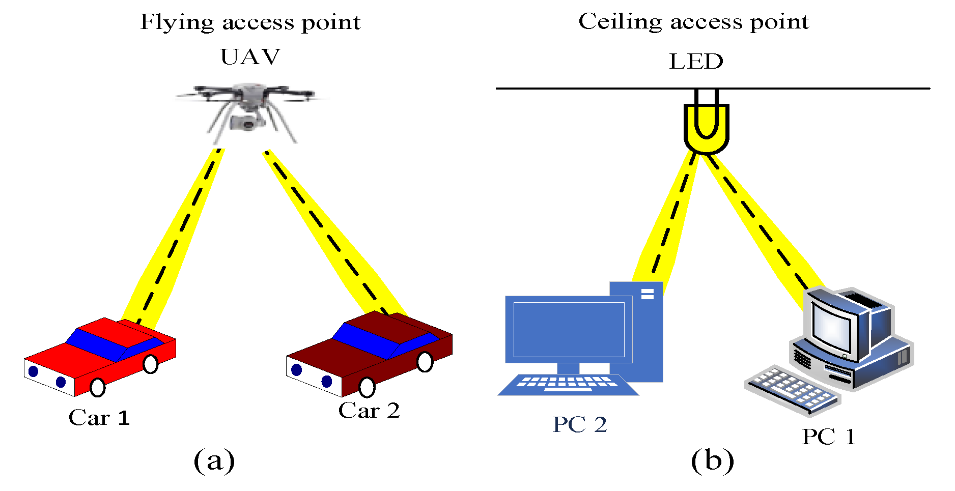
Although DFTS-OPAM using PAM symbols results in half the spectral efficiency compared with DCO-OFDM, it offers a 2.5 dB lower power consumption. However, if both schemes are considered as multiple access schemes based on time division multiple access (TDMA) techniques, as in VLC-V2X and other systems as illustrated in Figure 1 (i.e., indoor ceiling access point and outdoor flying access point applications), they would provide the same spectral efficiency. This is because the odd time domain samples in DFTS-OPAM do not carry any data. In addition, these unused samples can also be utilized for various vehicular traffic environment applications such as illumination, security, positioning, localization, and time domain equalization. Furthermore, due to the RM process, any affected DFTS-OPAM subcarrier can be easily compensated [19].
1.2. Contributions of this Paper
In the context of using VLC for V2X communications under dense vehicular environments, a visible Light Networking framework for Connected Vehicles (LiNEV) is presented in this paper. The major contributions of this paper are as follows:
- A system model for a novel multiple access scheme to enable VLC-V2X traffic use cases is developed.
- The workflow of the model is mathematically derived for highlighting the scientific novelty of the model.
- An extensive performance evaluation of the proposed framework is carried out under the influence of different QAM orders with a range of LED-DR values and limited LED bandwidth.
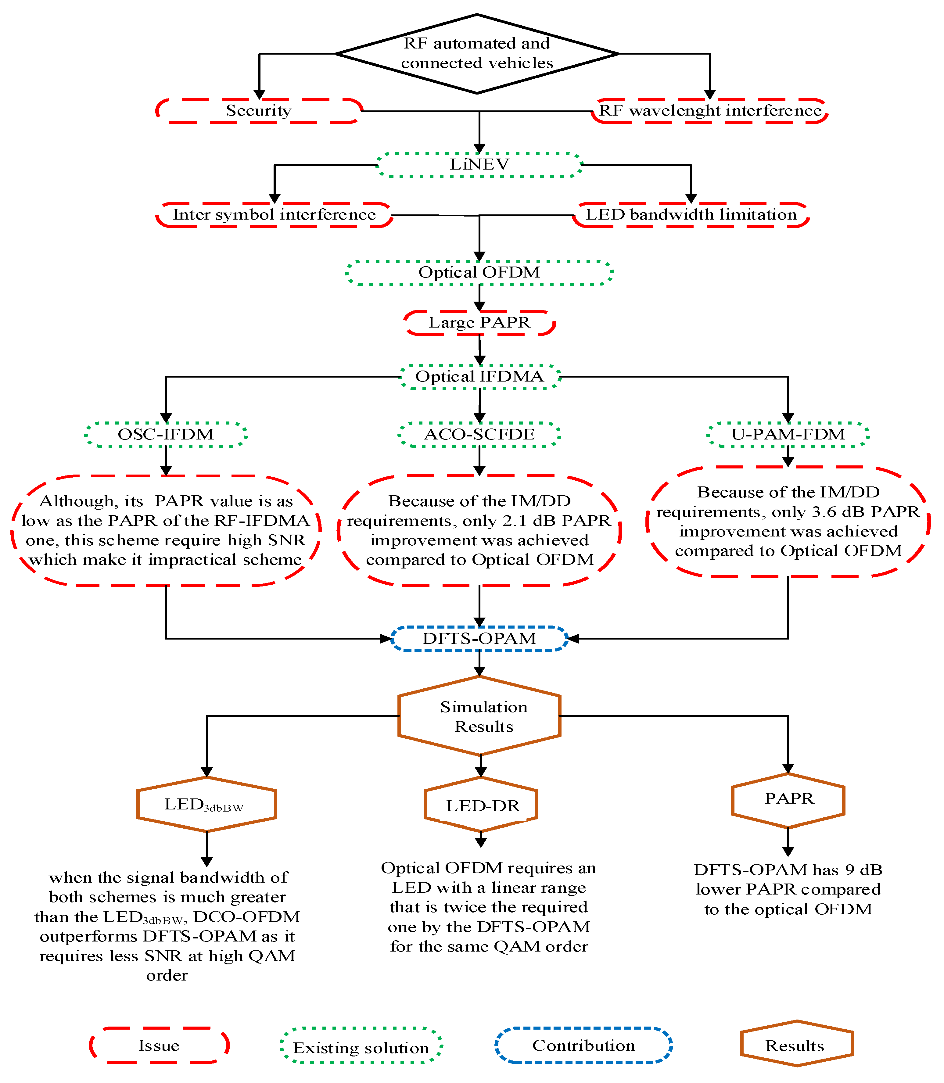
However, to visually illustrate these contributions, we have included Figure 2, which presents a detailed contribution map of our paper.
2. LiNEV: DFTS-OPAM for Connected Vehicles
2.1. System Model
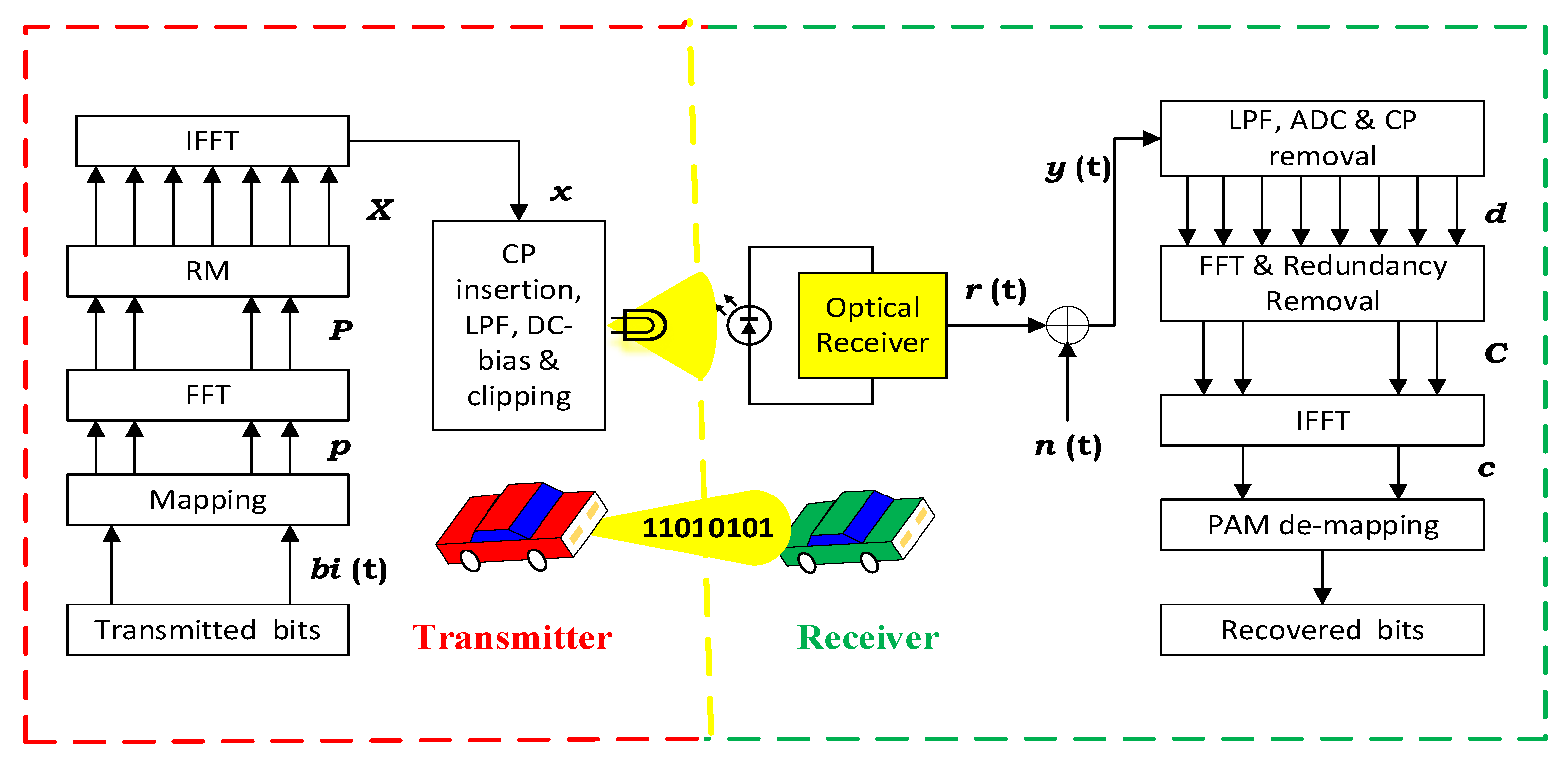
Figure 3 illustrates a block diagram of the DFTS-OPAM transceiver. The only difference between the DFTS-OPAM Tx and the traditional DCO-OFDM Tx is that the HS block at the DCO-OFDM is replaced by FFT, and RM blocks. Also, the PAM is used in DFTS-OPAM as a transmitted symbol instead of QAM. In [19], we mathematically and practically proved that the output of the DFTS-OPAM IFFT x is a real signal with similar DCO-OFDM features (i.e., reducing the ISI and bit and power loading features) and with as low a PAPR as the single-carrier modulation. Information and/or security data (i.e., text, image, or video message) are firstly converted to a stream of binary bits (i.e., A converted to 01000001) and input to the transmitter side of Figure 3 to be processed before being intensity-modulated and transmitted to the Rx by the LED headlight. In order to increase the transmitted data rate, these binary bits are converted to parallel bits and mapped to PAM symbols, where the order of PAM depends on the SNR level (i.e., a low SNR requires a low PAM order, and vice versa). For example, [0, 1, 0, 0, 0, 0, 0, 0, 1] is mapped to [−1, 1, −1, −1, −1, −1, −1, 1] or [−1, −3, −3, −1] for 2- and 4-PAM mapping symbols, respectively. To reduce the ISI as well as to transmit symbols even beyond the 3 dB LED modulation bandwidth, these PAM symbols pass to the IFFT operation. As such, the symbol time duration is now greater than the maximum time delay spread duration of the VLC-V2X channel (i.e., the signal bandwidth is divided into several sub-bands, where each sub-band is less than the VLC-V2X channel coherence bandwidth).
However, implementing IFFT operation to a number of PAM symbols results in a complex and high PAPR time domain signal, while the LEDs used in cars’ headlights have a limited linear dynamic range and only modulate the real time domain signals. To make the IFFT output time domain signal real with low a PAPR value, we inserted FFT and RM blooks before the implementation of the IFFT operation, as will be explained in more detail in the following subsection. As such, we introduced a real time domain signal with a low PAPR value that can overcome the ISI issue and transmit data even beyond the LED 3 dB modulation bandwidth. Finally, this sampled signal was converted to an analog signal before being intensity-modulated and transmitted as a light signal by the LED.
2.2. Workflow of DFTS-OPAM
The signal processing steps at the Tx are described as follows. First, the serial binary bits are converted into parallel data streams and mapped onto a group of real PAM symbols P as given by , where M is the number of data symbols. The real symbols are then transformed to the frequency domain by being passed to the FFT implementation, as given by:
where is the data frequency domain at the subcarrier, , and is the number of used subcarriers. Because the FFT inputs are PAM symbols, the output FFT data subcarriers are symmetrically conjugated around , except the as was mathematically proved in [19] and is illustrated in Figure 4.
P is passed to the RM block, where the output vector X is a double of P, as illustrated in (2) and shown in Figure 5.
Then, X is converted back to the time domain vector x by being implemented in the IFFT operation. However, as was mathematically proved in [19], because of the FFT and RM processes, the even samples of x are a version of p, and the odd ones are zeros, as illustrated in (3). Indeed, x has the characteristics of a single carrier with a low PAPR.
From Equation (3a), the following equation can be deduced:
Therefore, the odd and even samples of x can be, respectively, defined as:
where is the sample of x, l is the subcarrier of X, and is the number of OFDM samples after the RM process.
It is important to note that in DFTS-OPAM, the FFT operation initially spreads the symbols across the subcarriers, and if the IFFT operation is directly applied without reordering any subcarriers, it would effectively undo the spreading, leading to a signal similar to conventional single-carrier modulation. To address this issue while ensuring a consistent PAPR and preserving the real-time requirements of VLC systems, the RM block was implemented between the FFT and IFFT blocks at the DFTS-OPAM Tx (please see Equation (3) and Figure 3).
Finally, x is passed through parallel to serial (P/S) converter, cyclic prefix (CP) insertion, digital to analog converter (DAC), low-pass filter (LPF), DC bias, and clipping processes before being intensity-modulated and transmitted by the LED.
Following optical detection, the received electrical signal is , where , R is the photodiode responsivity, is the transmitted optical signal, the symbol denotes the linear convolution operation, is the impulse response of the system, and is the additive white Gaussian noise (AWGN). Note that, for the purpose of simplicity and without the loss of generality, we assume that . Then, is passed to LPF, analog to digital converter (ADC), CP removal, and serial to parallel (S/P) converter processes before being converted to the frequency domain by the FFT process. Finally, redundant subcarriers are removed and the result signal is passed to the IFFT and PAM de-mapping blocks to recover the transmitted bits.
3. Simulation Results
In this study, we have focused on evaluating the performance of the proposed system using well-established simulation models. While we acknowledge that additional experimental results could provide more specific insights into the system’s performance under different conditions, we believe that the simulation-based approach provides valuable and representative findings.
In these simulations, there were 256 IFFT points and 4-, 16-, 64- and 256-QAM constellation points for both DCO-OFDM and DFTS-OPAM. Note that for DFTS-OPAM, the PAM symbols were created by separating the real and the imaginary parts of QAM symbols (i.e., the QAM symbol was separated into ‘a’ and ‘b’ PAM symbols, where these symbols were recovered and combined at the Rx to reconstruct the QAM). The LED3dbBW was 10 MHz, the channel was considered as AWGN, and, to avoid the ISI, the CP duration () as well as the subcarrier bandwidth () of both schemes were chosen, as defined in (4) [20].
where is the root mean square time delay spread for the VLC-V2X multipath channel at an 18 m Inter-vehicular distance [21]. Finally, regarding the third generation partnership project (3GPP) standards, the EVM of 4-, 16-, 64- and 256-QAM should be less or equal to 17.5%, 12.5%, 8%, and 3.5%, respectively [22,23]. In this study, we defined these threshold values as EVMopt.
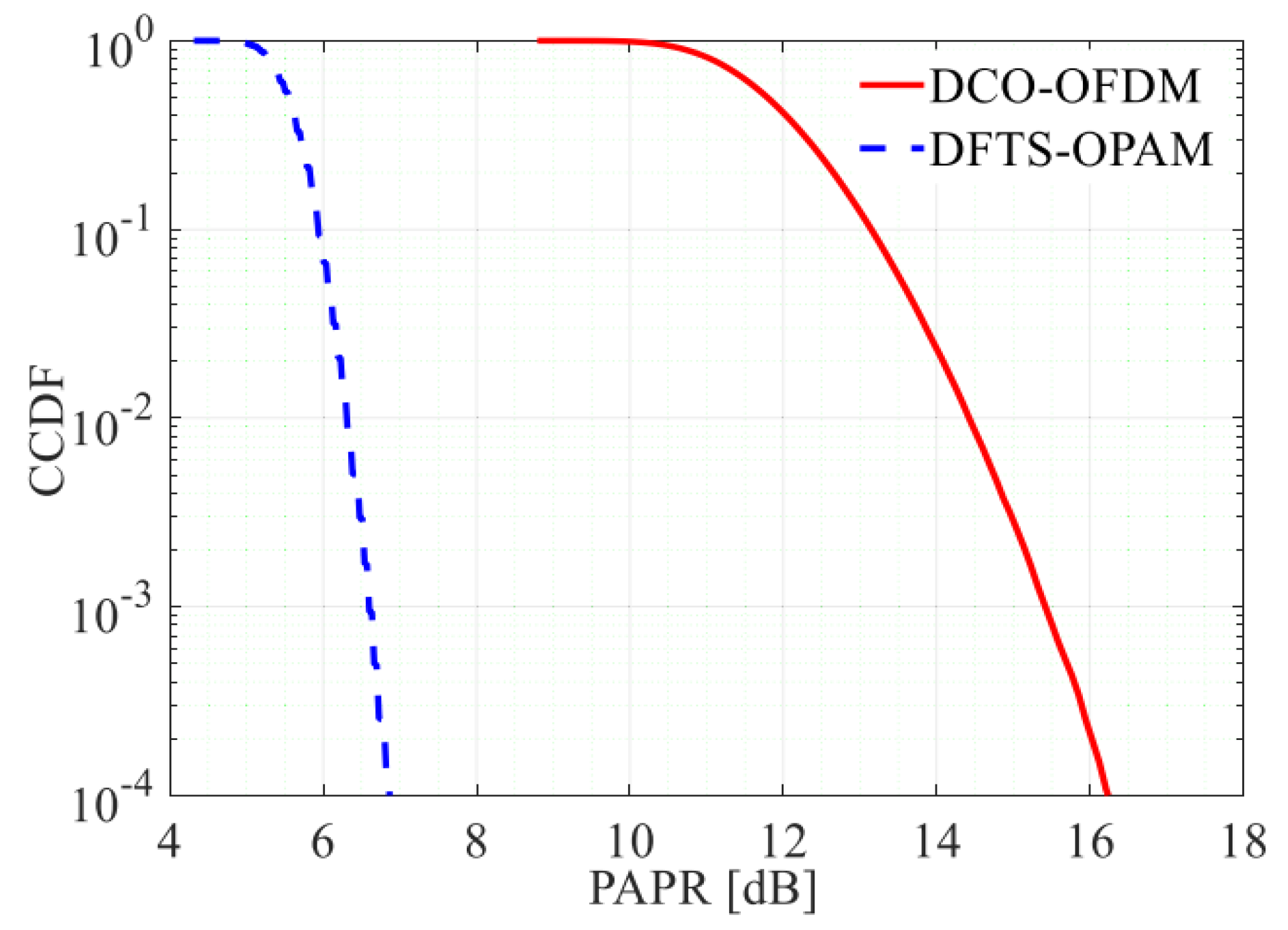
Figure 6 shows that the probability of the PAPR values of both schemes is higher than a certain threshold level (i.e., PAPR0), for which a complementary cumulative distribution function (CCDF) value of 10−4, i.e., pr {PAPR > PAPR0} = 0.0001, is considered [24,25]. In this figure, it is illustrated that DCO-OFDM has a 9 dB higher PAPR value compared with DFTS-OPAM. This PAPR improvement of the DFTS-OPAM scheme is due to the insertion of the FFT and the RM blocks prior to IFFT at the OFDM Tx.
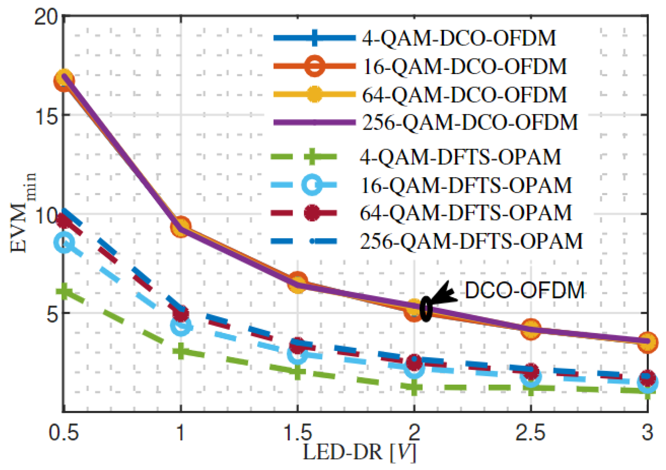
The minimum achievable EVM% (EVMmin) of DCO-OFDM and DFTS-OPAM at different values of the LED-DR and QAM orders is investigated in Figure 7. As in [15], the average power of the AWGN () was set to −10 dBm and the average transmitted power () of both schemes varied from 0 dBm to 30 dBm (i.e., 10 dB ≤ SNR ≤ 40 dB), where the EVMmin was achieved when the reached the maximum linear range of the LED, as the clipping noise occurred just after this value and, consequently, the EVM% started increasing again. The figure illustrates that implementing 256-, 64-, 16- and 4-QAM for DCO-OFDM or DFTS-OPAM requires an LDE with a linear dynamic range greater or equal to 3, 1.3, 0.8, and 0.5 V for the former and 1.5, 0.65, 0.5, and 0.3 V for the later.
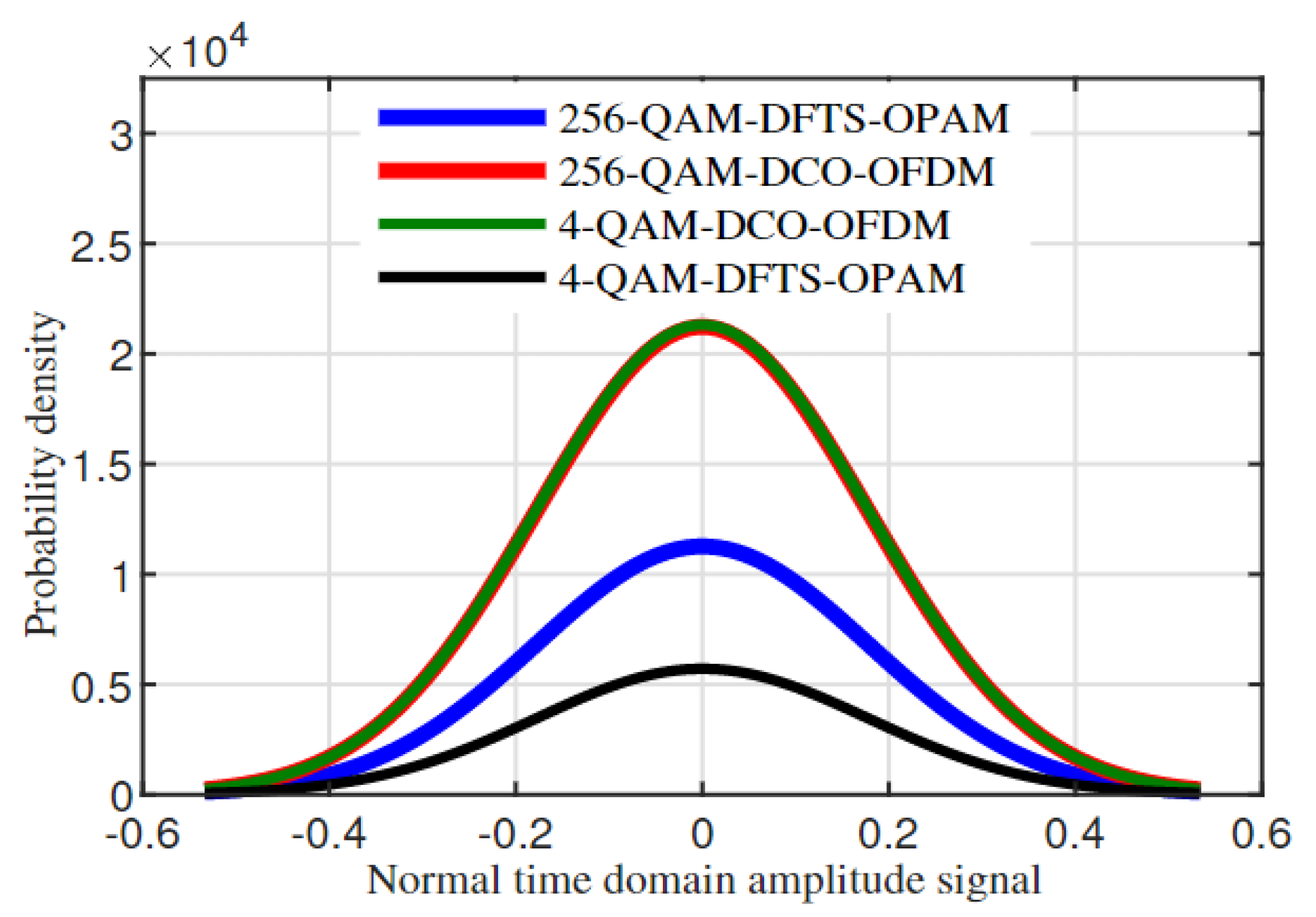
The figure also depicts that changing the QAM orders of the DCO-OFDM scheme has an unnoticeable impact on the EVMmin, while it causes variations in EVMmin values in DFTS-OPAM. This can be justified in Figure 8, which illustrates the probability density function of the normal time domain signal amplitude for both techniques at modulation orders of 4 and 256. The figure shows that changing the QAM orders of DFTS-OPAM varies the standard deviation of distribution, while it remains constant regardless of the QAM orders in DCO-OFDM.
As the main purpose of the headlight LED is to provide illumination, the diming control parameter should be considered in VLC systems. Diming control can be achieved by adjusting the DC bias above and beyond the middle point of the LED-DR, which is limited by the maximum and minimum values of the (). Values of and for different QAM orders of both schemes are provided in Table 1. As such, the DC bias of both schemes can only be varied from to , as increasing above or below these values will introduce upper or below clipping noise, respectively.
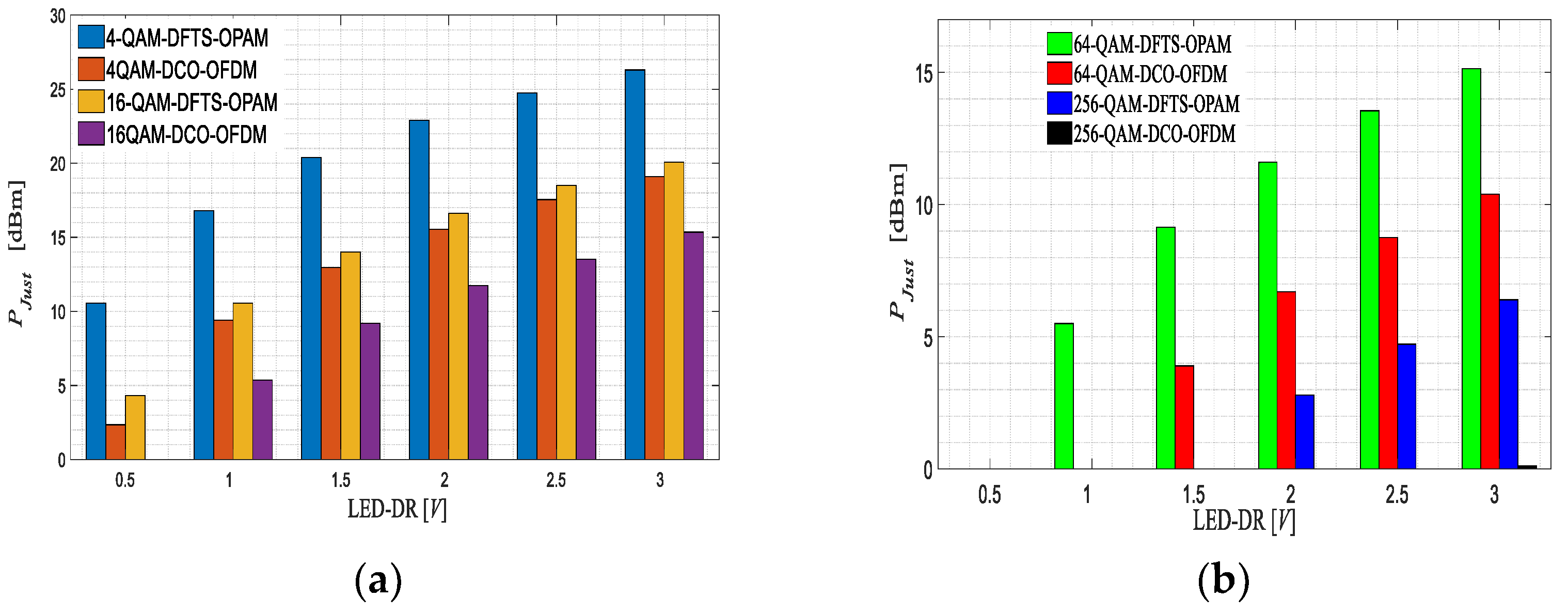
The adjusted available power values () of both schemes are illustrated in Figure 9. From the figure, it can be clearly noticed that increasing the LED-DR value as well as decreasing the QAM order of both schemes provides wider diming control. However, from the same figure, it can also be recognized that DFTS-OPAM outperforms DCO-OFDM in terms of supporting diming control. For example, the average power of DFTS-OPAM can be justified by 10 dBm around the LED-DR middle point without causing a clipping error when the 4-QAM order and the 0.5 V LED-DR are considered, while the average power of the DCO-OFDM can only be justified by 2 dBm around the LED-DR middle points for the same given assumptions, resulting in DFTS-OPAM providing wider dimming control compared with DCO-OFDM.
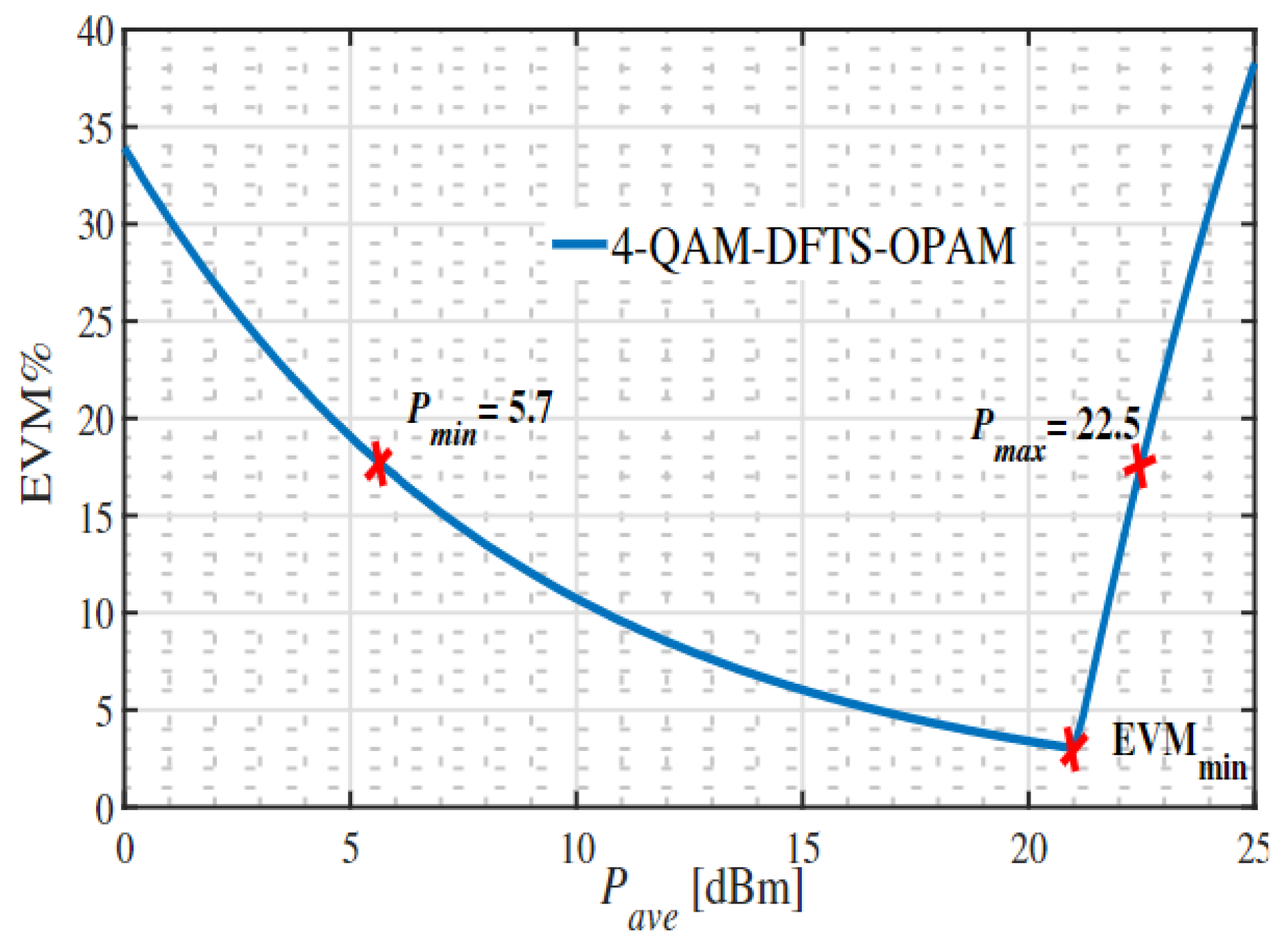
Figure 10 provides an example of how , and EVMmin were measured in this paper. The figure illustrates EVM% against for 4 QAM DFTS-OPAM, where LED-DR = 1 V, = −10 dBm, and varied from 0 dBm to 30 dBm. The figure shows that the EVM decays with increasing until it reaches EVMmin. After this turning point, EVM increases again as reaches the maximum value of the LED-DR, and hence, clipping noise occurs. and were achieved when EVM = EVMopt = 17.5% before and after EVMmin, respectively.
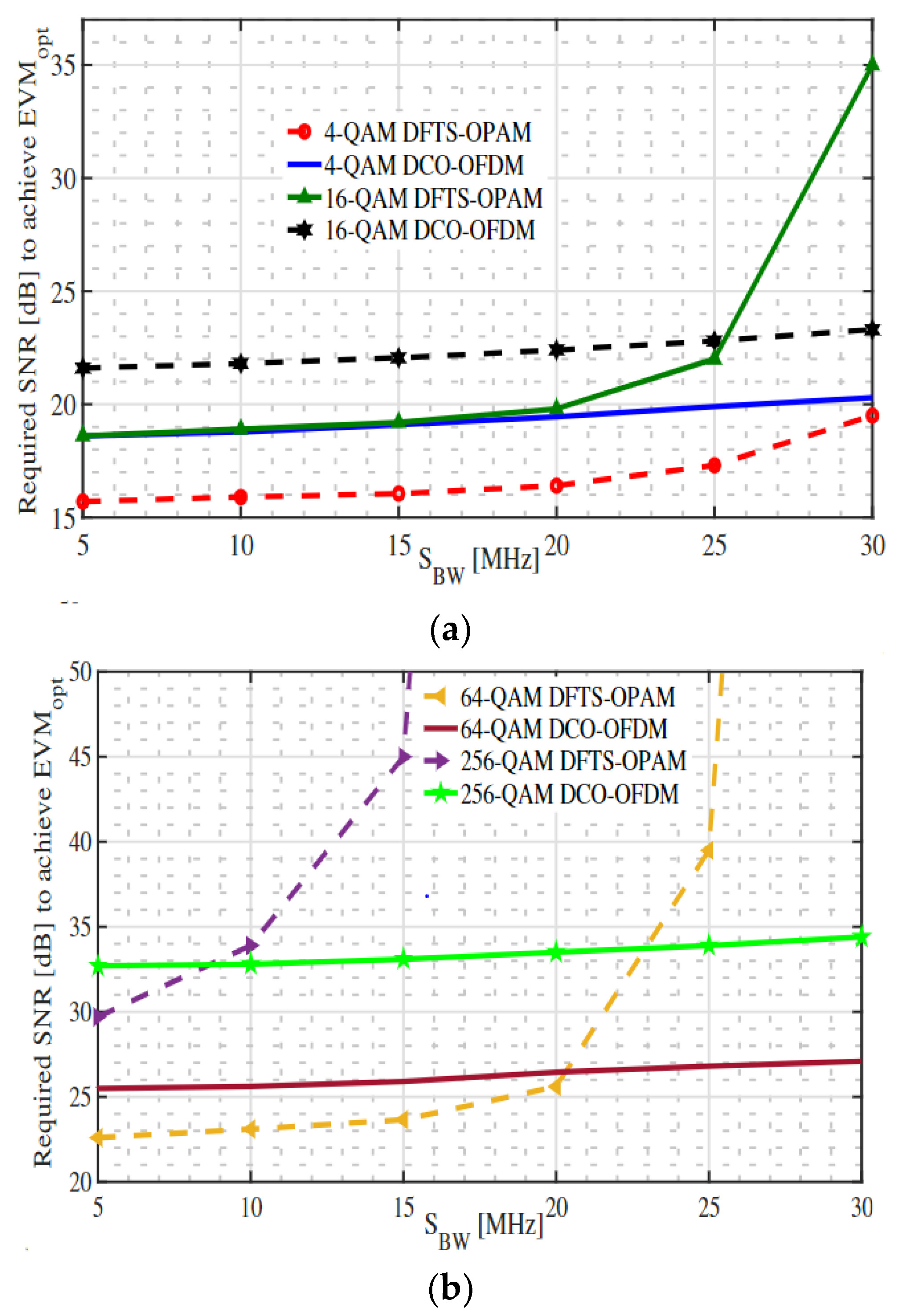
Finally, Figure 11 illustrates the minimum required SNR to achieve EVMopt versus signal bandwidth (SBW) for different QAM orders of DCO-OFDM and DFTS-OPAM schemes where an LED3dbBW of 10 MHz is considered, while the signal bandwidth of both schemes varied from 5 MHz to 30 MHz and the minimum required SNR to obtain EVMopt for both schemes was measured at 5, 10, 15, 20, 25 and 30 MHz. The figure shows that when SBW ≤ LED3dbBW (i.e., SBW ≤ 10 MHz), DFTS-OPAM outperforms DCO-OFDM for all QAM orders, as it requires less SNR to achieve EVMopt and that is because DFTS-OPAM has a lower PAPR.
However, transmitting data beyond LED3dbBW (i.e., SBW ≥ 10 MHz) more severely impacted the performance of DFTS-OPAM than DCO-OFDM, particularly at high QAM orders and high SBW values. This is due to the FFT implementation at the DFTS-OPAM, as the errors that occurred from the subcarriers located beyond the LED3dbBW will spread across all transmitted symbols in DFTS-OPAM, while they will only affect these subcarriers in DCO-OFDM. For instance, the 16-, 64- and 256-QAM DCO-OFDM outperformed the 16-, 64- and 256-QAM DFTS-OPAM when SBW was greater or equal to 2.5 LED3dbBW, 2 LED3dbBW, and LED3dbBW, respectively. However, as already illustrated, the (i.e., the SNR) of both schemes is limited by the limited LED-DR. For example, to obtain a 30 dB SNR value for = −10 dBm, an LED with a 3 V and 1.5 V linear dynamic range is required for the DCO-OFDM and DFTS-OPAM schemes, respectively.
4. Conclusions and Future Work
In this paper, we introduced the DFTS-OPAM scheme as a multiple access scheme for visible light networking in connected vehicle systems, replacing the traditional DCO-OFDM. The decision to adopt DFTS-OPAM was motivated by its significant lower PAPR value in the time domain compared with that of DCO-OFDM. The system performance of the DCO-OFDM and DFTS-OPAM schemes under the influence of limitations such as the LED dynamic range and the 3 dB LED bandwidth were compared.
Simulation results demonstrated that DFTS-OPAM outperforms DCO-OFDM when considering a narrow LED-DR. Specifically, DFTS-OPAM requires an LED with a linear range that is half of what is needed for DCO-OFDM. Additionally, DFTS-OPAM showed superior performance in terms of supporting dimming control compared with DCO-OFDM, which struggled to support dimming control, especially with a narrow LED-DR or a high order of QAM. Furthermore, we observed that when both schemes transmitted signals below the 3 dB LED modulation bandwidth, DCO-OFDM outperformed DFTS-OPAM at high QAM orders, while DFTS-OPAM surpassed DCO-OFDM at low QAM orders.
In future research, the bit and power loading feature of both schemes will be investigated using artificial intelligence techniques. By leveraging the achieved diversity of this feature, we aim to enhance the physical layer security of the LiNEV framework systems. The utilization of artificial intelligence will enable us to optimize the allocation of bits and power across the system, thereby improving the overall security performance. This research will contribute to the development of more robust and secure LiNEV communication systems.
Author Contributions
Conceptualization O.S.; Formal analysis O.S.; Investigation, O.S.; Methodology, O.S.; Resources, O.K.; Supervision, O.K. and S.K.; Validation, O.K.; Writing, O.S.; Review and Editing, O.K., M.A., M.M., R.K., F.A.-S. and C.C.T.; All authors have read and agreed to the published version of the manuscript.
Funding
This research is funded by the QR-Fund of the B11 Unit of Assessment, Computing and Informatics Research Center, Department of Computer Science, Nottingham Trent University, UK.
Data Availability Statement
Research data will be available on individual requests to the corresponding author considering collaboration possibilities with the researcher or research team and with restrictions that the data will be used only for further research in the related literature progress.
Conflicts of Interest
The authors declare no conflict of interest.
References
- Matheus, L.E.M.; Vieira, A.B.; Vieira, L.F.M.; Vieira, M.A.M.; Gnawali, O. Visible Light Communication: Concepts, Applications and Challenges. IEEE Commun. Surv. Tutor. 2019, 21, 3204–3237. [Google Scholar] [CrossRef]
- Chi, N.; Wei, Y.; Hu, F. Visible Light Communication in 6G: Advances, Challenges, and Prospects. IEEE Veh. Technol. Mag. 2020, 15, 93–102. [Google Scholar] [CrossRef]
- Cervinka, D.; Ahmad, O.S.; Rajbhandari, S. A Study of Yearly Sunlight Variance Effect on Vehicular Visible Light Communication for Emergency Service Vehicles. In Proceedings of the IEEE 12th International Symposium on Communication Systems, Networks and Digital Signal Processing (CSNDSP), Porto, Portugal, 20–22 July 2020. [Google Scholar]
- Kaiwartya, O.; Kumar, S. Guaranteed geocast routing protocol for vehicular adhoc networks in highway traffic environment. Wirel. Pers. Commun. 2015, 83, 2657–2682. [Google Scholar] [CrossRef]
- Khasawneh, A.M.; Helou, M.A.; Khatri, A.; Aggarwal, G.; Kaiwartya, O.; Altalhi, M.; Abu-Ulbeh, W.; AlShboul, R. Service-centric heterogeneous vehicular network modeling for connected traffic environments. Sensors 2022, 22, 1247. [Google Scholar] [CrossRef] [PubMed]
- Lee, I.E.; Sim, M.L.; Kung, F.W.L. Performance enhancement of outdoor visible-light communication system using selective combining receiver. IET Optoelectron. 2009, 3, 30–39. [Google Scholar] [CrossRef]
- Islim, M.S.; Videv, S.; Safari, M.; Xie, E.; McKendry, J.J.D.; Gu, E.; Dawson, M.D.; Haas, H. The impact of solar irradiance on visible light communications. J. Light. Technol. 2018, 36, 2376–2386. [Google Scholar] [CrossRef] [Green Version]
- Bian, R.; Tavakkolnia, I.; Haas, H. 15.73 Gb/s Visible Light Communication with Off-the-Shelf LEDs. J. Light. Technol. 2019, 37, 2418–2424. [Google Scholar] [CrossRef] [Green Version]
- Chronopoulos, S.K.; Vasilis, C.; Giorgos, T.; Tatsis, G. Performance of turbo coded OFDM under the presence of various noise types. J. Wirel. Pers. Commun. 2016, 87, 1319–1336. [Google Scholar] [CrossRef] [Green Version]
- Dissanayake, S.D.; Armstrong, J. Comparison of ACO-OFDM, DCO-OFDM and ADO-OFDM in IM/DD Systems. J. Light. Technol. 2013, 31, 1063–1072. [Google Scholar] [CrossRef]
- Chronopoulos, S.K.; Tatsis, G.; Vasilis, R.; Kostarakis, P. Enhanced PAPR in OFDM without deteriorating BER performance. J. Wirel. Pers. Commun. 2011, 4, 164. [Google Scholar] [CrossRef] [Green Version]
- Zhang, X.; Han, L.; Wang, J.; Ling, X.; Gao, X. PAPR Reduction under EVM Constraint in DCO-OFDM Systems. In Proceedings of the IEEE 21st International Conference on Communication Technology (ICCT), Tianjin, China, 13–16 October 2021. [Google Scholar]
- Lin, B.; Tang, X.; Yang, H.; Ghassemlooy, Z.; Zhang, S.; Li, Y.; Lin, C. Experimental Demonstration of IFDMA for Uplink Visible Light Communication. EEE Photonics Technol. Lett. 2016, 28, 2218–2220. [Google Scholar] [CrossRef]
- Mesleh, R.; Elgala, H.; Haas, H. LED nonlinearity mitigation techniques in optical wireless OFDM communication systems. IEEE OSA J. Opt. Commun. Netw. 2012, 4, 865–875. [Google Scholar] [CrossRef]
- Saied, O.; Ghassemlooy, Z.; Zvanovec, S.; Kizilirmak, R.C.; Lin, B. Unipolar-pulse amplitude modulation frequency division multiplexing for visible light communication systems. Opt. Eng. 2020, 59, 096108. [Google Scholar] [CrossRef]
- Wu, C.; Zhang, H.; Xu, W. On visible light communication using LED array with DFT-Spread OFDM. In Proceedings of the IEEE International Conference on Communications (ICC), Sydney, NSW, Australia, 10–14 June 2014. [Google Scholar]
- Saied, O.; Ghassemlooy, Z.; Kizilirmak, R.C.; Dai, X.; Ribeiro, C.; Zhang, M.; Rajbhandari, S. Single carrier optical FDM in visible light communication. In Proceedings of the IEEE 10th International Symposium on Communication Systems, Networks and Digital Signal Processing (CSNDSP), Prague, Czech Republic, 20–22 July 2016. [Google Scholar]
- Saied, O.; Ghassemlooy, Z.; Rajbhandari, S.; Burton, A. Optical single carrier-interleaved frequency division multiplexing for visible light communication systems. Optik 2019, 194, 162910. [Google Scholar] [CrossRef]
- Saied, O.; Li, X.; Rabie, K.M. DFT Spread-Optical Pulse Amplitude Modulation for Visible Light Communication Systems. IEEE Access 2022, 10, 15956–15967. [Google Scholar] [CrossRef]
- Turan, B.; Narmanlioglu, O.; Koc, O.N.; Kar, E.; Coleri, S.; Uysal, M. Measurement Based Non-Line-of-Sight Vehicular Visible Light Communication Channel Characterization. IEEE Trans. Veh. Technol. 2022, 71, 10110–10114. [Google Scholar] [CrossRef]
- Turan, B.; Gurbilek, G.; Uyrus, A.; Ergen, S.C. Vehicular VLC Frequency Domain Channel Sounding and Characterization. In Proceedings of the IEEE Vehicular Networking Conference (VNC), Taipei, Taiwan, 5–7 December 2018. [Google Scholar]
- Li, H.; Hu, R.; Yang, Q.; Luo, M.; He, Z.; Jiang, P.; Liu, Y.; Li, X.; Yu, S. Improving performance of mobile fronthaul architecture employing high order delta-sigma modulator with PAM-4 format. Opt. Exp. 2017, 25, 1–9. [Google Scholar] [CrossRef] [PubMed]
- ETSI TS 136 104; Evolved Universal Terrestrial Radio Access (E-UTRA). Base Station (BS) Radio Transmission and Reception (3GPP TS 36.104 Version 8.6. 0 Release 8). ETSI: Sophia Antipolis, France, 2009. Available online: https://www.etsi.org/deliver/etsi_ts/136100_136199/136104/14.03.00_60/ts_136104v140300p.pdf (accessed on 1 May 2023).
- Wang, M.; Jiang, Y.; Zhu, X.; Li, H.; Wang, T. Multi-Layer Superimposed PAPR Reduction for ACO-OFDM VLC Systems. In Proceedings of the IEEE International Conference on Communications (ICC), Seoul, Republic of Korea, 16–20 May 2022. [Google Scholar]
- Zhang, T.; Ji, H.; Ghassemlooy, Z.; Tang, X.; Lin, B.; Qiao, S. Spectrum-Efficient Triple-Layer Hybrid Optical OFDM for IM/DD-Based Optical Wireless Communications. IEEE Access 2020, 8, 10352–10362. [Google Scholar] [CrossRef]
Figure 1.
TDMA-VLC applications where (a) uses UAV as flying access point to assist vehicular communication while an LED is used in (b) as a ceiling access point to provide indoor multiple access.
Figure 1.
TDMA-VLC applications where (a) uses UAV as flying access point to assist vehicular communication while an LED is used in (b) as a ceiling access point to provide indoor multiple access.

Figure 2.
Paper contribution map.

Figure 3.
DFTS-OPAM transceiver block diagram.

Figure 4.
The subcarriers for eight real input samples at the output of the FFT module.

Figure 5.
The subcarriers for eight real input samples at the RM module.

Figure 6.
CCDF vs. PAPR for DCO-OFDM and DFTS-OPAM, where 256 IFFT points were considered.

Figure 7.
EVMmin versus LED-DR for DCO-OFDM and DFTS-OPAM.

Figure 8.
Probability density function of the normal time domain signal amplitude for DCO-OFDM and DFTS-OPAM at QAM modulation orders of 4 and 256.
Figure 8.
Probability density function of the normal time domain signal amplitude for DCO-OFDM and DFTS-OPAM at QAM modulation orders of 4 and 256.

Figure 9.
for DCO-OFDM and DFTS-OPAM, where different QAM orders and different LED-DR values are considered, (a) 4–16 QAM, (b) 64–256 QAM.
Figure 9.
for DCO-OFDM and DFTS-OPAM, where different QAM orders and different LED-DR values are considered, (a) 4–16 QAM, (b) 64–256 QAM.

Figure 10.
EVM versus for 4-QAM DFTS-OPAM, where 1 V LED-DR is considered.

Figure 11.
Required SNR to achieve EVMOpt versus SBW for different QAM orders of DCO-OFDM and DFTS-OPAM schemes where LED3dbBW of 10 MHz is considered, (a) 4-16 QAM, (b) 64-256 QAM.
Figure 11.
Required SNR to achieve EVMOpt versus SBW for different QAM orders of DCO-OFDM and DFTS-OPAM schemes where LED3dbBW of 10 MHz is considered, (a) 4-16 QAM, (b) 64-256 QAM.


Table 1.
and of DCO-OFDM and DFTS-OPAM schemes.
| DCO-OFDM QAM Orders | DFTS-OPAM QAM Orders | ||||||||
|---|---|---|---|---|---|---|---|---|---|
| 4 | 16 | 64 | 256 | 4 | 16 | 64 | 256 | ||
| LED-DR = 0.5 | 11.1 | 0 | 0 | 0 | 16.25 | 13 | 0 | 0 | |
| 8.75 | 0 | 0 | 0 | 5.7 | 8.68 | 0 | 0 | ||
| LED-DR = 1 | 18.15 | 17 | 0 | 0 | 22.5 | 19.25 | 17.75 | 0 | |
| 8.75 | 11.65 | 0 | 0 | 5.7 | 8.68 | 12.25 | 0 | ||
| LED-DR = 1.5 | 21.7 | 20.85 | 19.5 | 0 | 26.1 | 22.7 | 21.4 | 20.05 | |
| 8.75 | 11.65 | 15.6 | 0 | 5.7 | 8.68 | 12.25 | 20 | ||
| LED-DR = 2 | 24.3 | 23.4 | 22.3 | 0 | 28.6 | 25.3 | 23.85 | 22.8 | |
| 8.75 | 11.65 | 15.6 | 0 | 5.7 | 8.68 | 12.25 | 20 | ||
| LED-DR = 2.5 | 26.3 | 25.18 | 24.36 | 0 | 30.45 | 27.2 | 25.8 | 24.72 | |
| 8.75 | 11.65 | 15.6 | 0 | 5.7 | 8.68 | 12.25 | 20 | ||
| LED-DR = 3 | 27.84 | 27 | 26 | 23.21 | 32 | 28.75 | 27.4 | 26.4 | |
| 8.75 | 11.65 | 15.6 | 23.2 | 5.7 | 8.68 | 12.25 | 20 | ||
Disclaimer/Publisher’s Note: The statements, opinions and data contained in all publications are solely those of the individual author(s) and contributor(s) and not of MDPI and/or the editor(s). MDPI and/or the editor(s) disclaim responsibility for any injury to people or property resulting from any ideas, methods, instructions or products referred to in the content. |
© 2023 by the authors. Licensee MDPI, Basel, Switzerland. This article is an open access article distributed under the terms and conditions of the Creative Commons Attribution (CC BY) license (https://creativecommons.org/licenses/by/4.0/).
Share and Cite
MDPI and ACS Style
Saied, O.; Kaiwartya, O.; Aljaidi, M.; Kumar, S.; Mahmud, M.; Kharel, R.; Al-Sallami, F.; Tsimenidis, C.C. LiNEV: Visible Light Networking for Connected Vehicles. Photonics 2023, 10, 925. https://doi.org/10.3390/photonics10080925
AMA Style
Saied O, Kaiwartya O, Aljaidi M, Kumar S, Mahmud M, Kharel R, Al-Sallami F, Tsimenidis CC. LiNEV: Visible Light Networking for Connected Vehicles. Photonics. 2023; 10(8):925. https://doi.org/10.3390/photonics10080925
Chicago/Turabian StyleSaied, Osama, Omprakash Kaiwartya, Mohammad Aljaidi, Sushil Kumar, Mufti Mahmud, Rupak Kharel, Farah Al-Sallami, and Charalampos C. Tsimenidis. 2023. "LiNEV: Visible Light Networking for Connected Vehicles" Photonics 10, no. 8: 925. https://doi.org/10.3390/photonics10080925
Note that from the first issue of 2016, this journal uses article numbers instead of page numbers. See further details here.