
Investigating Laser-Induced Periodic Surface Structures (LIPSS) Formation in Silicon and Their Impact on Surface-Enhanced Raman Spectroscopy (SERS)

1
Martin Luther University Halle-Wittenberg, ZIK Sili-Nano, Halle, Germany
2
Fraunhofer Center for Silicon Photovoltaics CSP, Halle, Germany
*
Author to whom correspondence should be addressed.
Optics 2023, 4(4), 538-550; https://doi.org/10.3390/opt4040039
Submission received: 1 September 2023
/
Revised: 11 October 2023
/
Accepted: 12 October 2023
/
Published: 19 October 2023
(This article belongs to the Special Issue Laser-Assisted Micro- and Nano-Fabrications)
Abstract
:Laser-induced periodic surface structures (LIPSS) have gained significant attention due to their ability to modify the surface morphology of materials at the micro-nanoscale and show great promise for surface functionalization applications. In this study, we specifically investigate the formation of LIPSS in silicon substrates and explore their impact on surface-enhanced Raman spectroscopy (SERS) applications. This study reveals a stepwise progression of LIPSS formation in silicon, involving three distinct stages of LIPSS: (1) integrated low-spatial-frequency LIPSS (LSFL) and high-spatial-frequency LIPSS (HSFL), (2) principally LSFL and, (3) LSFL at the edge of the irradiated spot, elucidating the complex interplay between laser fluence, pulse number, and resulting surface morphology. Furthermore, from an application standpoint, these high-quality multi-scale periodic patterns lead to the next step of texturing the entire silicon surface with homogeneous LIPSS for SERS application. The potential of LIPSS-fabricated silicon substrates for enhancing SERS performance is investigated using thiophenol as a test molecule. The results indicate that the Au-coated combination of LSFL and HSFL substrates showcased the highest enhancement factor (EF) of . This pronounced enhancement is attributed to the synergistic effects of localized surface plasmon resonance (LSPR) and surface plasmon polaritons (SPPs), intricately linked to HSFL and LSFL characteristics. These findings contribute to our understanding of LIPSS formation in silicon and their applications in surface functionalization and SERS, paving the way for sensing platforms.
Keywords:
laser-induced periodic surface structures (LIPSS); surface-enhanced Raman spectroscopy (SERS); femtosecond laser; ultrashort laser; low-spatial-frequency LIPSS (LSFL); high-spatial-frequency LIPSS (HSFL); localized surface plasmon resonance (LSPR); surface plasmon polaritons (SPPs); nanostructuring1. Introduction
Recently, laser-induced periodic surface structures (LIPSS) have gained remarkable attention because of their micro-nanoscale resolution. Laser-induced periodic surface structures (LIPSS) can be generated on various classes of materials, including metals, semiconductors, dielectrics, and polymers, by utilizing linearly polarized ultrashort laser pulses [1]. Because of its unique properties, LIPSS can be used in a wide range of applications in fields such as medicine, optics, tribology, biology, and many more [1,2,3]. The emergence of laser-induced periodic surface structures (LIPSS) on various materials opens up new possibilities for enhancing surface properties, modifying surface topography, improving light–matter interactions, and promoting specific functionalities [4]. Generally, laser-induced periodic surface structures (LIPSS) are categorized based on their spatial period. They are divided into two main types: low-spatial frequency LIPSS (LSFL) and high-spatial frequency LIPSS (HSFL). Low-spatial frequency LIPSS (LSFL) are characterized by periods larger than half of the laser irradiation wavelength, whereas high spatial frequency LIPSS (HSFL) exhibit periods smaller than half of the incident wavelength [5]. Generally, under low fluence conditions, HSFLs are observed, aligned parallel to the polarization of the laser beam. However, as the fluence is increased to a higher regime, LSFL becomes more prominent and exhibits a perpendicular orientation to the laser beam polarization. This transition from HSFL to LSFL occurs as the fluence increases and the number of laser pulses decreases [6]. The formation mechanism of LIPSS in silicon is attributed to the surface plasmon polaritons (SPPs) [7]. When a laser beam interacts with a metal or semiconducting substrate, it can excite collective oscillations of electrons known as surface plasmons. These surface plasmons are coupled to the incident light and propagate along the surface, forming LIPSS [8]. There are many theories regarding the formation of LIPSS, such as the Sipe theory [9], Drude model [10] for transient optical properties, second-harmonic generation [11], self-organization model [12] for high fluence regime, and many more. Several experimental and theoretical studies have extensively investigated the formation of LIPSS on silicon by varying laser and process parameters [7,13,14]. Based on the knowledge gained, research has increasingly shifted toward developing tailored LIPSS for surface functionalization applications.
SERS has become one of the most versatile and powerful analytical techniques in molecule sensing due to its ultrahigh sensitivity up to a single molecule [15,16]. Surface-enhanced Raman scattering can be enhanced through two main methods: chemical and electromagnetic. However, it is considered that the electromagnetic effect is predominantly responsible for the amplification of the SERS signal [17,18]. SERS primarily employs plasmonics, which investigate the interaction between incident light and metallic nanostructures, leveraging the electromagnetic effect to enhance the Raman signal through specially designed nanostructures [16,19]. Their nanostructures are random-morphology metallic SERS substrates or periodic or ordered metallic SERS substrates. However, the morphology and shape of random metallic SERS substrates are arbitrary and non-reproducible, resulting in varying SERS efficiency [20]. Several alternative patterning strategies, including electron beam lithography, nano-imprint lithography, and soft lithography, have been proposed as alternative approaches that offer sufficient spatial resolution, uniformity, and reproducibility for biomedical applications [21,22,23]. However, these processes require complex multiple-step clean-room procedures with continuous high-precision chemical and thermal processes that are time-consuming and expensive. Alongside sophisticated fabrication techniques, cost-effective approaches such as self-assembly, colloid lithography, or laser structuring have emerged [24,25,26]. Laser structuring is often favored for SERS due to its precise laser-controlled structuring, which ensures superior uniformity and repeatability compared to self-assembly and colloid lithography methods. Due to the simpler fabrication process, cost-effectiveness, and greater design flexibility, LIPSS structures are preferred as SERS substrates [4]. Ag or Au nanoparticle deposition on laser-textured substrates is common for SERS applications. These substrates include glass [27], silicon [28], polymer [29], and metals [30]. A recent study shows the around Raman enhancement of Methylene Blue (MB) molecules using a laser-structured gold-coated silicon substrate [31]. Erkizan et al. demonstrated that using LIPSS on silicon with a subsequent thin noble metal (Ag) layer deposition led to SERS substrates achieving Raman enhancement factors up to [32]. In addition to 1D LIPSS, 3D LIPSS structures are also employed as SERS platforms [33]. In addition to LIPSS on silicon, porous silicon can also substantially enhance SERS sensitivity due to its increased surface area, amplifying the electromagnetic fields within its microstructures [34]. Three-dimensional multilayered SERS substrates introduce additional plasmonic hot spots along the z-axis. This substrate detects even lower molecular concentrations, offering significant advancements for SERS-based applications [35,36].
This study focuses on investigating the formation of HSFL and LSFL on silicon by femtosecond laser irradiation. The experimental analysis in this study is performed by systematically varying the fluence (F) from 0.70 cm to 2 cm and pulse number (N) from 0 to 3000. This investigation provides insights into the interplay between these parameters and their effects on the formation of HSFL and LSFL. Furthermore, we have developed three distinct substrates by employing different pulse and line overlapping techniques: LSFL + HSFL, LSFL, and LSFL surrounding the nanohole. Subsequently, a thin layer of gold was deposited onto the substrate to make a SERS platform. This work demonstrates the effectiveness of the LSFL and HSFL approach for SERS applications, showcasing the significant enhancement achieved in the Raman signal.
2. Experimental Work and Methodology
2.1. Fabrication of LIPSS on Silicon Substrates
An industrial ultrashort pulse laser carried out surface irradiation (Yb: KGW laser, Pharos from Light Conversion Ltd.) with a pulse duration of 180 fs emitting in the near-infrared ( nm) with an average power of 6W and operating at repetition rates up to 600 kHz. The laser ablation experiments were performed on polished crystalline silicon (orientation <100>) with a thickness of 500 m at a fixed repetition rate of 100 kHz. The femtosecond laser pulses were focused to a spot radius of 20 m () at normal incidence to the substrate surface. The sample was placed on a motorized linear XYZ stage. A half-wave plate was positioned before the Galvo scanner cyan(intelliSCAN from Scanlab, Puchheim, Germany ) to change the polarization state of the pulses before focusing. To obtain the homogeneous LIPSS on silicon, we varied the fluence, pulse overlapping, line overlapping, and pulse number. After femtosecond laser processing, all samples were ultrasonically cleaned in isopropanol. The surface morphologies of the LIPSS structure have been characterized by scanning electron microscopy (SEM).
2.2. Deposition of Gold Nanoparticles onto Silicon Substrates
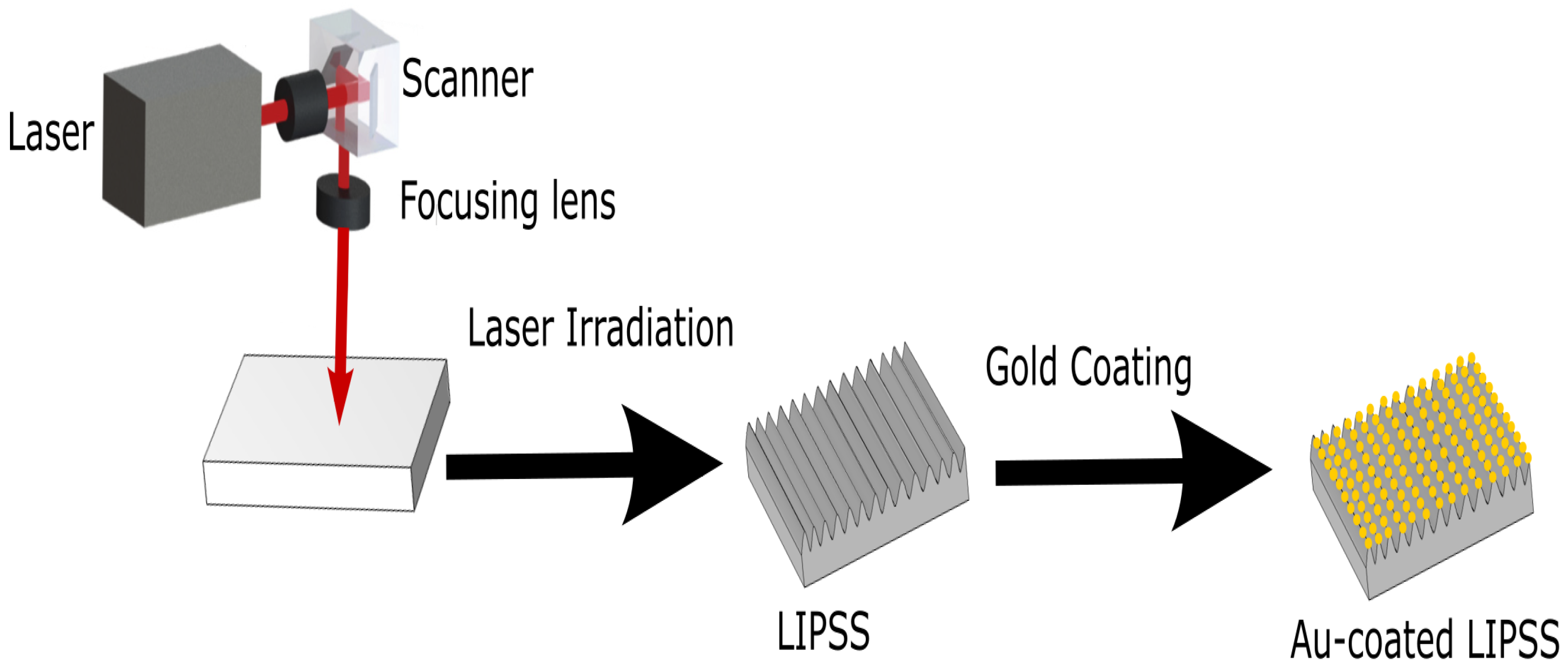
Gold (Au) thin film was deposited onto laser-fabricated nanostructures using 10 kV electron beam (e-beam) evaporation (Malz & Schmidt GbR, Meissen, Germany) with a base pressure lower than Torr. The primary objective of this fabrication process was to achieve surface amplification of the Raman signal. By integrating the gold nanoparticles onto the LIPSS substrate generated through laser processing, we aimed to create additional “hotspots” that could support strongly localized surface plasmons. These hotspots, in turn, contribute to a higher enhancement in the Raman signal [37]. The morphology and homogeneity of the deposited nanoparticle were examined by scanning electron microscopy. Depositing Au film on LIPSS structures causes it to fragment into nanoparticles due to the LIPSS topography and the specific LIPSS pattern influences the resulting nanoparticle distribution and behavior [38]. The LIPSS experimental procedure and the fabrication of the Au nanoparticles are shown in Figure 1.
2.3. SERS Experiments
A solution of thiophenol (99.8% purity, sourced from Sigma-Aldrich, Louis, MO, USA) was prepared at a concentration of 1 mM in ethanol (sourced from Sigma-Aldrich, Louis, MO, USA). For subsequent SERS experiments, droplets of this thiophenol solution were carefully placed onto the Au-coated LIPSS substrates. These droplets were then left to dry under atmospheric conditions. Raman spectra were obtained using Raman Spectrometer LabRAM HR Evolution from Horiba and a 785 nm wavelength laser light was used as the excitation source. The Raman spectra were acquired by collecting scattered light in backscattering geometry, using a magnification objective of 100×. The Raman data were obtained with an acquisition time of 5 s and five accumulations. Moreover, laser polarization was fixed throughout the Raman measurements.
3. Results and Discussion
3.1. Evolution of LIPSS on Silicon
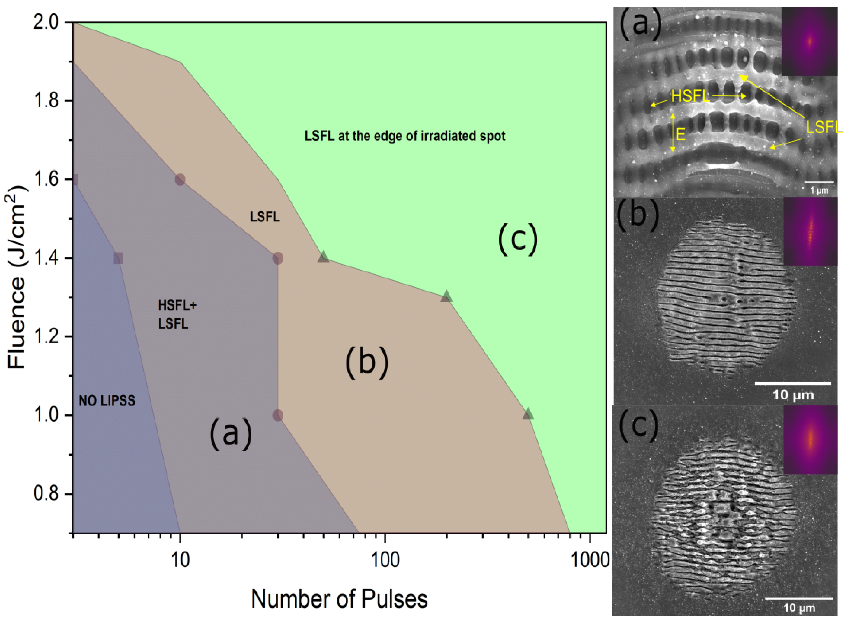
In this study, we investigated the influence of laser fluence and the number of pulses on the formation of LIPSS in silicon through femtosecond laser irradiation. Figure 2 illustrates the parameter regimes, plotting the fluence against the number of laser pulses that lead to the formation of LIPSS on silicon. By systematically varying these two parameters, we gained valuable insights into the underlying mechanisms governing LIPSS formation and explored the optimal conditions for their generation.
The experimental results demonstrated three distinct stages in the evolution of the LIPSS formation: HSFL + LSFL, LSFL, and LSFL at the edge of the irradiated spot. In the initial stages of laser irradiation, characterized by low fluence and a small number of pulses, the formation of LIPSS is not observed. However, LIPSS to the complete ablation became evident with the increased fluence and the number of pulses. This marked the transition to the first regime (stage I) of HSFL and LSFL, where the number of pulses and fluence were progressively increased. The orientation of the LSFL is perpendicular to the electric field, while the orientation of HSFL is parallel to the electric field. Figure 2a depicts the definitive crossed structure with mixed HSFL and LSFL. LSFL is superposed to the underlying HSFL, revealing a cross-structure that combines both types at the impact. The formation of LSFL and HSFL is attributed to surface plasmon polaritons (SPPs). Two types of SPPs, one at the plasma–air interface and the other at the plasma–substrate interface generate distinct ripple structures during the femtosecond laser irradiation of silicon [39]. In metals, two periodic surface structures, LSFL and HSFL, are formed by forward and backwards-propagating SPPs, as discussed by Fuentes et al. [40]. As the number of incident pulses increases, the HSFL structures begin to diminish, giving rise to the dominance of LSFL structures. This marks the transition to the second stage (stage II) of LIPSS formation. With further pulse accumulation, the central parts of the LIPSS are destroyed due to the Gaussian shape of the laser, leading to the formation of LSFL at the edge of the irradiated spot (stage III). Importantly, these three stages of LIPSS formation have been observed across a wide range of pulse fluences. However, it should be noted that a specific number of pulses is required to advance from one stage to the next. This stepwise progression in LIPSS formation has been visually demonstrated in Figure 2, showcasing scanning electron micrograph sequences at different stages in the silicon. The obtained results shed light on the complex interplay between laser fluence, pulse number, and the resulting surface morphology, paving the way for precise control of LIPSS formation in silicon.
3.2. Periodicity Dependence on Fluence and Number of Pulses
LIPSS formation, with a specific periodicity, occurs within a certain laser fluence range close to the material damage threshold and a particular number of pulses. Still, when the laser fluence is above that range and the number of pulses exceeds a certain limit, the stronger ablative regime completely cancels out the formation of LIPSS.
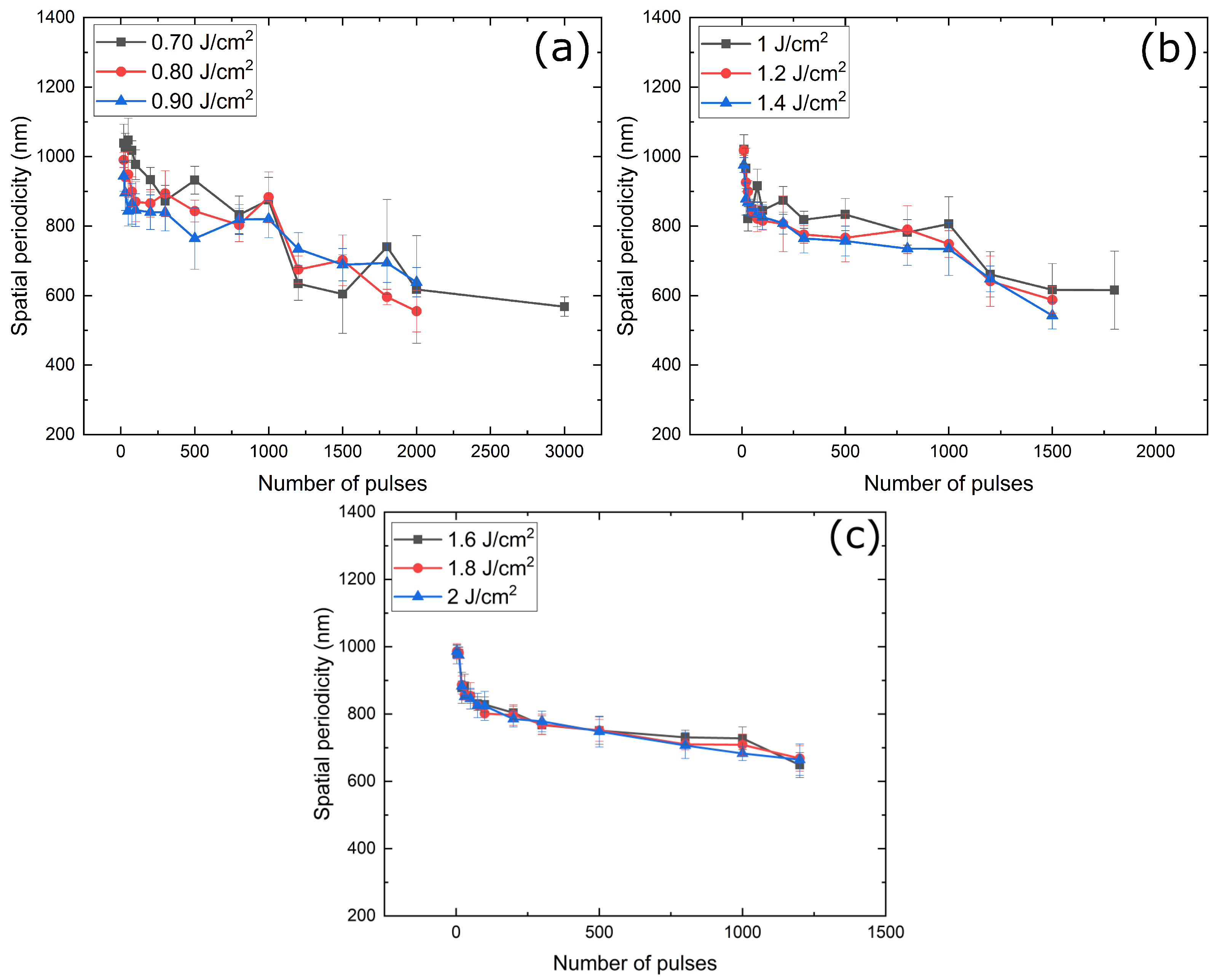
Figure 3 illustrates the spatial periodicity of the LIPSS structure as a function of laser fluence and the number of pulses at a wavelength of 1030 nm with a pulse duration of 180 fs. In the low fluence regime (<1 J/cm), we found that the average spatial periodicity of LIPSS decreased with increasing fluence for up to 1000 pulses. Moreover, the decrease in the LIPSS period with fluence is also consistent within the range of 150 nm. This behaviour is consistent with previous studies showing a correlation between fluence and LIPSS periodicity [13]. This decrease is attributed to the coupling between grating-like LSFL surface relief, formed during the initial laser pulses, and surface plasmon polaritons (SPPs) [41].However, beyond 1000 pulses, this trend is not consistently followed. A potential reason for this deviation might be due to the cumulative thermal effects or surface modifications that become more pronounced with a higher number of pulses. Increasing the laser fluence in silicon generates more carriers in the conduction band, altering the behaviour of SPPs. In the medium fluence regime (/cm/cm), our experimental findings revealed a fascinating trend: the dependency of the LIPSS period on fluence exhibited a significant reduction. As the fluence increases within the medium range, the interaction between the incident laser light and the silicon surface becomes stronger. This intensified interaction gives rise to a higher density of excited SPPs on the surface, which in turn influences the formation of LIPSS. The increased density of SPPs facilitates a more efficient redistribution of energy, leading to the emergence of LIPSS structures with a shorter period, and the influence of fluence on LIPSS periods becomes less pronounced [13,41,42]. As fluences rise, the energy deposition becomes more intense, leading to increased melting and re-solidification processes (without material removal), resulting in a more stable periodicity until the ablation occurs [7]. Our findings demonstrate a distinct behaviour compared to metals. In metal, it was found that the periodicity increased with increasing fluence in contrast to semiconductors [43,44,45]. The dependence of the larger periodicity of LIPSS on higher fluence levels in metals can be attributed to the induction of surface plasma waves through the parametric decay of laser light [43,45].
As shown in Figure 3, the LSFL period decreases from around 1030 nm to around 600 nm as the number of laser pulses increases from 10 to 3000 while impinging on the same spot at different fluence. The decrement of the LSFL period is particularly significant up to 1500 pulses, after which there is a slight variation in the periodicity. This observation indicates that the formation of LIPSS exhibits a pronounced decrease in period initially but reaches a point of stabilization beyond a certain number of pulses. The behaviour of the reduction in the LIPSS periodicity with increasing fluence or the number of pulses can be understood using the surface plasmon polaritons (SPPs) theory [7] or Grating-assisted surface plasmon-laser coupling [41]
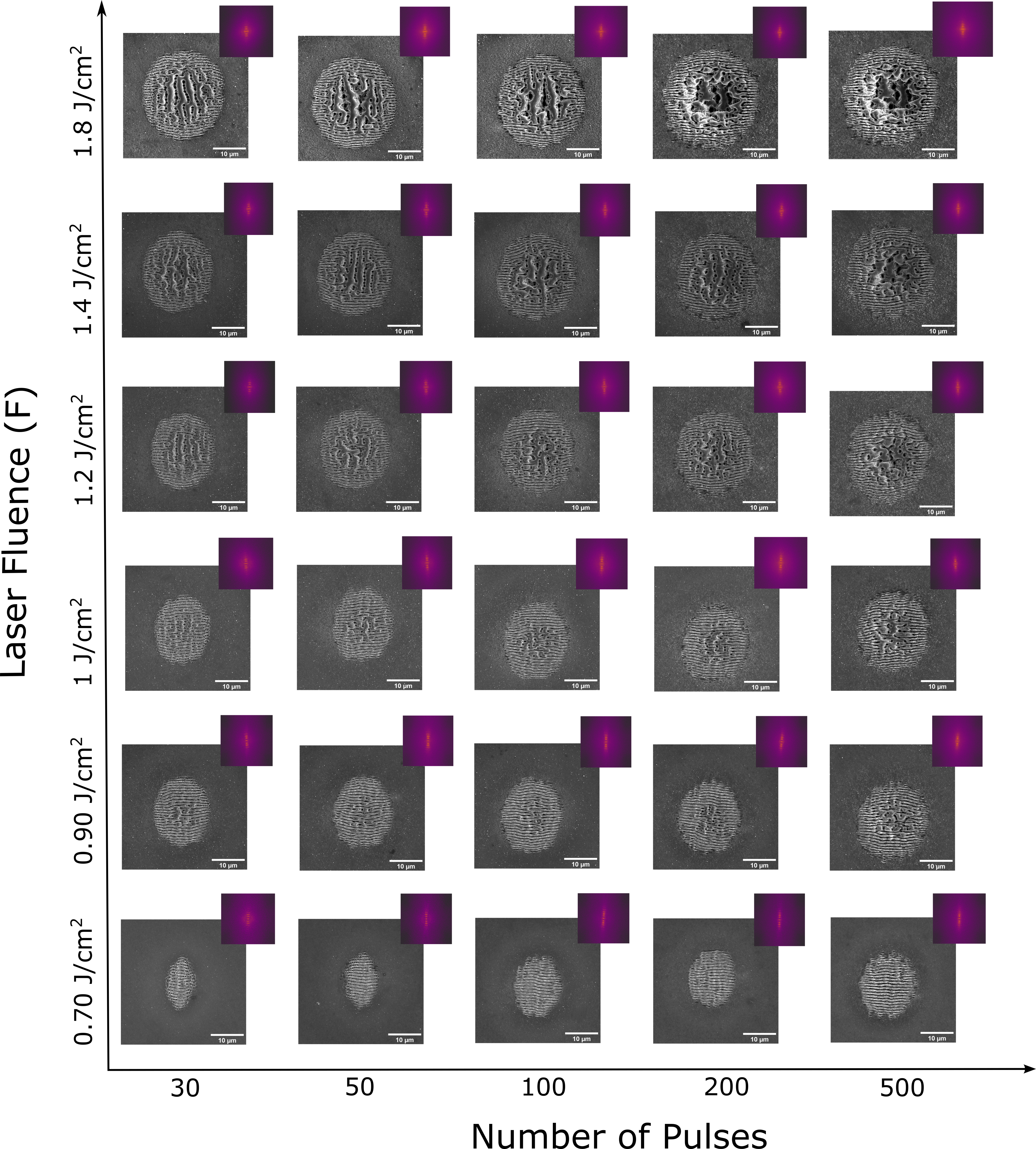
Figure 4 shows the dynamic evolution of the LIPSS in silicon by varying the fluence and number of pulses. It provides valuable insights into the relationship between these parameters and the resulting surface morphology. Near the ablation threshold of silicon, at a fluence of approximately 0.70 cm, the laser-induced surface modification exhibits intriguing multi-stage behaviour as the pulse number increases. The localized incident light within the subwavelength ripples causes their elongation, forming elliptically shaped LIPSS. These show different dimensions along the major and minor axes, contributing to their elliptical nature. However, as shown in Figure 4, as the pulse number increases from 30 to 200 at a fluence of 0.70 cm, an unexpected transition takes place. The initially formed elliptical LIPSS gradually evolved into more circular LIPSS. This transformation can be attributed to the complex interplay between various factors, including the redistribution of the electric field induced by the ripples, the interplay of interference effects, and surface plasmon polarization [42,46]. With the increase in pulse number, the anisotropic features of the LIPSS become less pronounced, resulting in a more circular morphology. By systematically increasing the pulse number and fluence, we notice a progressive transformation in the surface morphology, with a well-defined LIPSS structure emerging to the nanohole arrays within the LIPSS structure. Nanoplasmonic coupling is the underlying mechanism responsible for forming nanoholes within the LIPSS structure. This coupling refers to the interaction between incident light and localized surface plasmons. When incident laser light interacts with a LIPSS structure, the light is confined to the nano-surface area generated during the early stage of LIPSS formation. This confinement of light enhances the electric field distribution within the nano-surface area. The enhanced electric field can cause the ejection of material from the surface, leading to the formation of nanoholes [47]. As the pulse number and fluence further increase, the ablation process becomes more prominent. The enhanced electric field within the nanoholes leads to preferential ablation in those regions. Consequently, the material surrounding the nanoholes is gradually removed, forming an ablation carter. Surrounding the ablation crater is the LIPSS structure, which consists of the remaining surface morphology with nanohole arrays, as shown in Figure 4, at a fluence of 1.4 J/cm and a number of 500 pulses.
3.3. Fabrication of Large Area Si LIPSS and Damage Studies
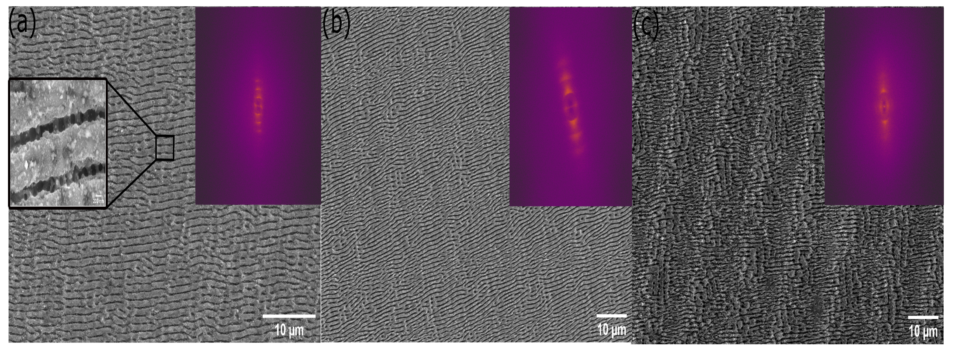
Building upon the understanding of SERS and LIPSS, recent investigations have focused on achieving homogeneously structured large areas on silicon substrates based on the fluence ranges and the number of pulses evaluated in the previous experiments. Figure 5 illustrates three different LIPSS substrates and their characteristics. The first substrate involved the coexistence of LSFL and HSFL. LSFL in this region was evaluated to be approximately 912 nm, while HSFL exhibited a period of approximately 246 nm. The second substrate concentrated solely on LSFL to examine its impact. In this area, the period of LSFL was found to be around 795 nm. The third substrate featured LSFL surrounding a centrally positioned ablation crater or nanohole. The period of the LIPSS in this section was measured to be 565 nm.
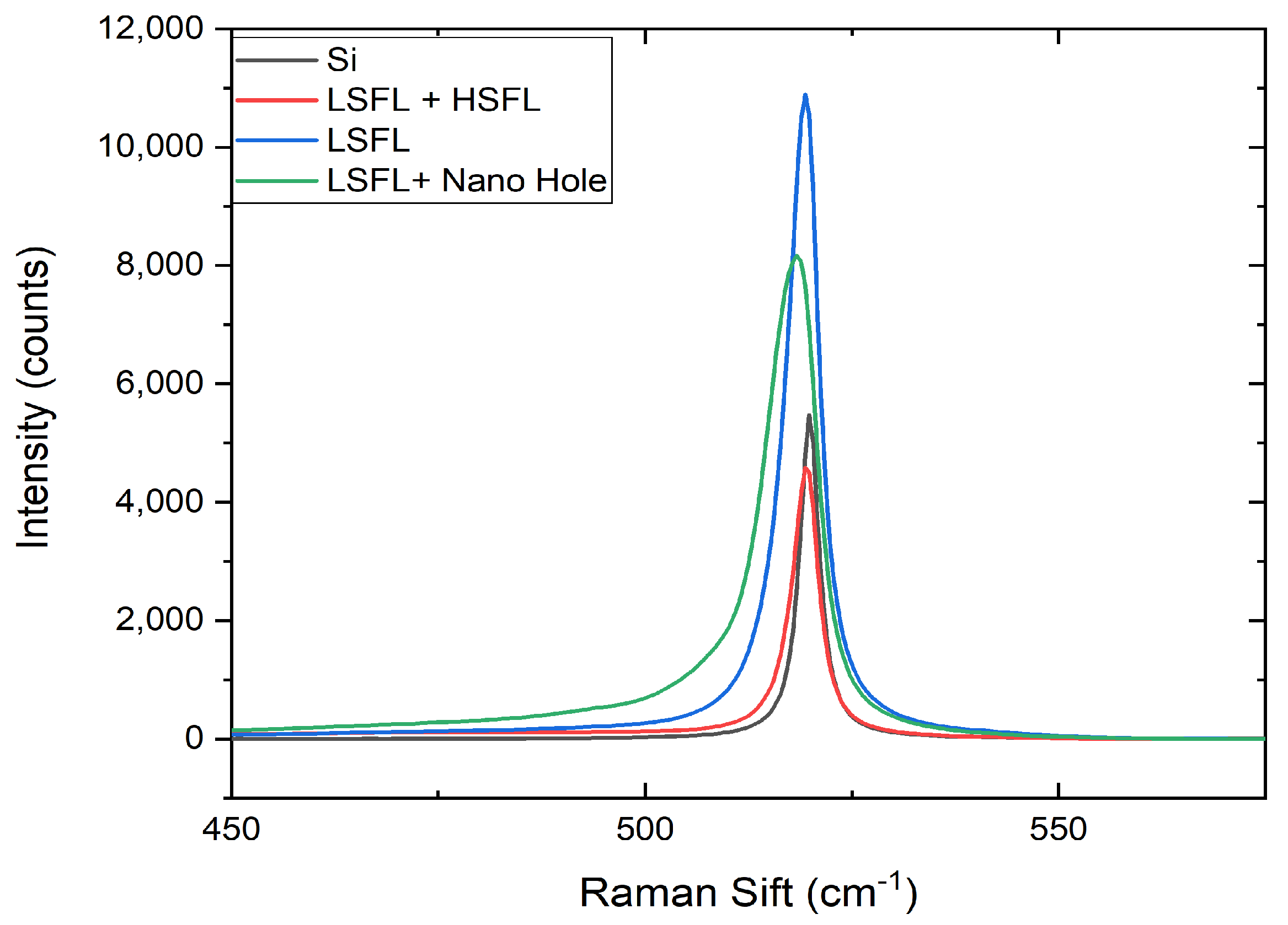
Prior to their use as substrates for SERS, the irradiated silicon samples were characterized by Raman measurements in order to get a deeper understanding of the modifications and stress induced by the laser. Through the Raman spectra analysis (Figure 6), notable observations were made across these stages. In the initial stage, where both LSFL and HSFL were present, no significant changes in the Raman spectra compared to crystalline silicon were observed. Progressing to the subsequent stages, namely LSFL dominance and LSFL with nanohole, Raman spectra analysis revealed a broadening of the silicon peaks. This broadening indicated alterations in the phonon dispersion and an increase in disorder within the silicon structure. While a complete conversion to amorphous silicon was not observed, the broadened spectra suggested the presence of an amorphous layer on the surface, signifying the formation of defects during the LIPSS generation process. LIPSS formation on silicon transforms a portion of monocrystalline Si (c-Si) to microcrystalline Si (mc-Si), shifting the Raman signal from 521 cm to 514 cm. This shift depends on the volume of mc-Si produced by the LIPSS fabrication process. The broadening shown in Figure 6 is the superimposition of the mc-Si and c-Si Raman lines. Because the Raman system has not been intensity-corrected at this stage, it is unclear how much mc-Si is produced by the LIPSS. A 50 nm gold thin film is deposited on the respective silicon substrates to create SERS substrates in these regions. This choice aligns with previous studies that consistently show that nano-particles with a diameter of 50 nm produce the maximum SERS enhancement [48]. The deposition of gold thin films on the structured silicon surfaces allows for generating localized surface plasmons, which can enhance the Raman signals of molecules. Detailed SEM and Raman analyses were performed after gold deposition on different LIPSS substrates. The deposition of the gold layer on LIPSS does not change the periodicity of the LIPSS substrate. Additionally, the Raman analysis indicated a flat response attributed to the gold layer’s mirror effect, resulting in no Raman peaks.
3.4. Sers Outcomes across LIPSS Stages
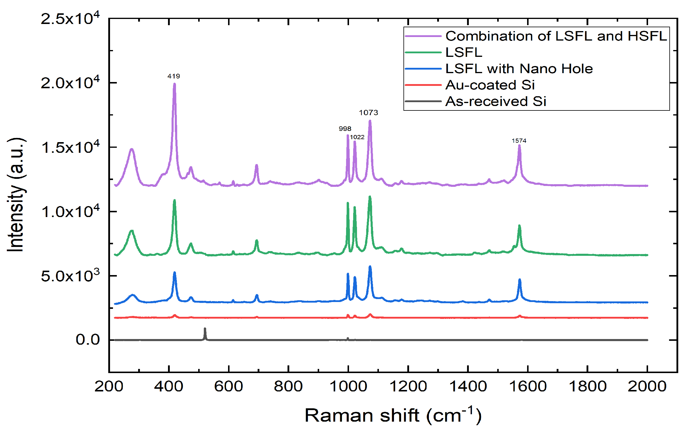
The aim of this study is to develop laser material processing-based techniques by exploiting the complex interaction between molecular resonances and LIPSS to achieve heightened SERS outcomes. The SERS characteristics were investigated using the thiophenol solution to assess the sensitivity of the Raman signal. The experimental setup involved dropping 1 mM thiophenol solution in ethanol onto different gold-coated substrates: untreated, LSFL coexisting with HSFL, LSFL substrate, and LSFL surrounding a central ablation crater or nanohole. Observing a Raman signal for the untreated silicon in its as-received state is very hard. Figure 7 illustrates the Raman spectrum obtained from these varied surfaces. The recorded Raman spectra for the range between 220 to 2000 cm distinctly exhibited the characteristic peaks of thiophenol. These peaks were observed at 419, 998, 1022, 1073, and 1574 cm, aligning with previous research findings [49,50,51]. The results showed that the intensity of the Raman signal was significantly increased using different LIPSS. Most notably, the combined LSFL and HSFL (Stage 1) induced a significantly higher Raman intensity, revealing a double-periodic profile highlighting the collaborative enhancement from these interlaced structures. Moreover, as we transitioned through the stages, a noticeable decrement in Raman intensities has been observed. In contrast to the first stage, the isolated LSFL substrate (second stage) showed diminished intensities. The intensities further decreased by the time we reached the third step, where LSFL was combined with a nanohole, underscoring the variances introduced by each LIPSS substrate.
Table 1 represents the Raman signal enhancement factor (EF) associated with the different substrates, focusing on 419, 998, 1022, 1073, and 1574 cm bands. At 419 cm, the Au-coated LSFL and HSFL substrate exhibited the highest enhancement factor (EF) of . In contrast, the LSFL substrate alone had an EF of , while the LSFL with a nanohole structure registered . Moreover, the periodicity of the LIPSS closely matches the wavelength of the incident Raman laser, which likely contributes to the slightly higher enhancement factor observed in Stage II compared to Stage I at the 998 peak. According to the SERS spectra (Figure 7) and EF (Table 1), the Raman enhancement factor (EF) order for the structures with three morphologies is Stage III < Stage II < Stage I.
EF of Raman predominantly increase from the amplification of the local electromagnetic (EM) field, initiated by mechanisms such as LSPR and surface plasmon polaritons [52]. SPPs represent propagating charge oscillations excited by the periodicity of LIPSS so that it effectively enhances SERS, especially when the periodicity aligns with the excitation wavelength [52]. LSPR is observed when metal nanoparticles have dimensions smaller than the incident wavelength. This causes a collective oscillation of the valence electrons within the metal nanoparticle, leading to an enhanced EM field around these particles [33]. Stage 2 (LSFL) and Stage 3 (LSFL with nanohole) excite surface plasmon polaritons (SPPs) due to their unidimensional periodicity. In contrast, with its intricate multi-directional structures, Stage I (LSFL and HSFL) supports the excitation of both SPPs and LSPR. This combined resonance effect in Stage I (LSFL and HSFL) substrate leads to a more pronounced concentration of electromagnetic fields, resulting in higher enhancement factor (EF) of the Raman signal compared to standard LIPSS structure.
4. Conclusions
In this work, the evolution of LIPSS formation on silicon has been systematically investigated by varying the laser fluence and number of pulses. Distinct stages in the evolution of LIPSS formation are identified, including: (1) integrated low-spatial-frequency LIPSS (LSFL) and high-spatial-frequency LIPSS (HSFL), (2) predominantly low-spatial-frequency LIPSS (LSFL), and (3) low-spatial-frequency LIPSS (LSFL) at the edge of the irradiated spot, presenting a systematic progression influenced by both fluence and pulse numbers. Importantly, this study revealed a notable interplay between laser fluence and LIPSS periodicity, wherein an increase in fluence within a given number of pulses led to a reduction in the spatial periodicity of the LIPSS. This behaviour was underpinned by the mechanism of surface plasmon polaritons (SPPs), where an increase in fluence correlates with a higher density of excited SPPs. Moreover, experimental results show that the LSFL period sharply decreases when increasing the number of pulses on the same spot before stabilizing, suggesting a threshold beyond which LIPSS periodicity remains largely consistent. The SERS characteristics of each stage were investigated using the thiophenol solution to access the sensitivity of the Raman signal. Among the observed structures, the Au-coated combined architecture of LSFL and HSFL in Stage I showcases a remarkable SERS enhancement of . This pronounced enhancement is due to the combined resonance effect of localized surface plasmon resonance (LSPR) and surface plasmon polaritons (SPPs). Contrastingly, the LSFL substrate registers a modest EF of . However, when LSFL is integrated with a nanohole structure, the peak EF slightly decreases to . This research pioneered the development of SERS-sensing platforms through three distinct structuring regimes of LIPSS by femtosecond laser. Moreover, experimental enhancement factors (EF) revealed that dual periodic structures are particularly advantageous for these sensing platforms due to their inherent double resonance.
Author Contributions
Conceptualization, H.V. and P.-T.M.; Methodology, H.V.; Formal analysis, H.V.; Investigation, H.V.; Writing − original draft, H.V.; Writing − review and editing, H.V. and P.-T.M.; Supervision, P.-T.M. All authors have read and agreed to the published version of the manuscript.
Funding
This work received financial support from the project “The German Federal Environmental Foundation” (Project No. DBU-AZ37730-01).
Data Availability Statement
The data that support the findings of this study are available upon reasonable request from the authors.
Acknowledgments
The authors thank Bodo Fuhrmann and Sven Schlenker for their valuable work in the deposition of gold particles on LIPSS.
Conflicts of Interest
The authors declare no conflict of interest.
References
- Gräf, S. Formation of laser-induced periodic surface structures on different materials: Fundamentals, properties and applications. Adv. Opt. Technol. 2020, 9, 11–39. [Google Scholar] [CrossRef]
- Vorobyev, A.Y.; Guo, C. Direct femtosecond laser surface nano/microstructuring and its applications. Laser Photonics Rev. 2013, 7, 385–407. [Google Scholar] [CrossRef]
- Florian, C.; Kirner, S.V.; Krüger, J.; Bonse, J. Surface functionalization by laser-induced periodic surface structures. J. Laser Appl. 2020, 32, 022063. [Google Scholar] [CrossRef]
- Bonse, J.; Kirner, S.V.; Krüger, J. Laser-induced periodic surface structures (LIPSS). In Handbook of Laser Micro-and Nano-Engineering; Springer: Cham, Switzerland, 2020; pp. 1–59. [Google Scholar]
- Bonse, J. Quo vadis LIPSS?—Recent and future trends on laser-induced periodic surface structures. Nanomaterials 2020, 10, 1950. [Google Scholar] [CrossRef]
- Shi, X.; Xu, X. Laser fluence dependence of ripple formation on fused silica by femtosecond laser irradiation. Appl. Phys. A 2019, 125, 256. [Google Scholar] [CrossRef]
- Bonse, J.; Rosenfeld, A.; Krüger, J. On the role of surface plasmon polaritons in the formation of laser-induced periodic surface structures upon irradiation of silicon by femtosecond-laser pulses. J. Appl. Phys. 2009, 106, 104910. [Google Scholar] [CrossRef]
- Bonse, J. Laser-Induced Periodic Surface Structures: When Maxwell meets Marangoni. In Proceedings of the 16th International Conference on Laser Ablation (COLA 2021/22), Matsue, Japan, 24–29 May 2022. [Google Scholar]
- Sipe, J.; Young, J.F.; Preston, J.; Van Driel, H. Laser-induced periodic surface structure. I. Theory. Phys. Rev. B 1983, 27, 1141. [Google Scholar] [CrossRef]
- Dufft, D.; Rosenfeld, A.; Das, S.; Grunwald, R.; Bonse, J. Femtosecond laser-induced periodic surface structures revisited: A comparative study on ZnO. J. Appl. Phys. 2009, 105, 034908. [Google Scholar] [CrossRef]
- Borowiec, A.; Haugen, H. Subwavelength ripple formation on the surfaces of compound semiconductors irradiated with femtosecond laser pulses. Appl. Phys. Lett. 2003, 82, 4462–4464. [Google Scholar] [CrossRef]
- Varlamova, O.; Reif, J.; Varlamov, S.; Bestehorn, M. Self-organized surface patterns originating from laser-induced instability. In Progress in Nonlinear Nano-Optics; Springer: Cham, Switzerland, 2015; pp. 3–29. [Google Scholar]
- Bonse, J.; Krüger, J. Pulse number dependence of laser-induced periodic surface structures for femtosecond laser irradiation of silicon. J. Appl. Phys. 2010, 108, 034903. [Google Scholar] [CrossRef]
- Chen, Y.; Peng, W.; Hu, X.; Zhang, C. Functional performance of Silicon with periodic surface structures induced by femtosecond pulsed laser. Coatings 2022, 12, 716. [Google Scholar] [CrossRef]
- Nie, S.; Emory, S.R. Probing single molecules and single nanoparticles by surface-enhanced Raman scattering. Science 1997, 275, 1102–1106. [Google Scholar] [CrossRef] [PubMed]
- Uskoković-Marković, S.; Kuntić, V.; Bajuk-Bogdanović, D.; Holclajtner Antunović, I. Surface-enhanced raman scattering (SERS) biochemical applications. In Encyclopedia of Spectroscopy and Spectrometry; Elsevier: Amsterdam, The Netherlands, 2017. [Google Scholar]
- Kosuda, K.; Bingham, J.; Wustholz, K.; Van Duyne, R.; Groarke, R. 4.06—Nanostructures and surface-enhanced Raman Spectroscopy. In Comprehensive Nanoscience and Nanotechnology; Elsevier: Amsterdam, The Netherlands, 2016; pp. 117–152. [Google Scholar]
- Kahraman, M.; Mullen, E.R.; Korkmaz, A.; Wachsmann-Hogiu, S. Fundamentals and applications of SERS-based bioanalytical sensing. Nanophotonics 2017, 6, 831–852. [Google Scholar] [CrossRef]
- Choi, J.; Lee, H.W.; Kim, B.S.; Choi, S.; Choi, J.; Song, J.; Cho, S. Mn-doped V 2 VI 3 semiconductors: Single crystal growth and magnetic properties. J. Appl. Phys. 2005, 97, 10D324. [Google Scholar] [CrossRef]
- Jing, Y.; Wang, R.; Wang, Q.; Xiang, Z.; Li, Z.; Gu, H.; Wang, X. An overview of surface-enhanced Raman scattering substrates by pulsed laser deposition technique: Fundamentals and applications. Adv. Compos. Hybrid Mater. 2021, 4, 885–905. [Google Scholar] [CrossRef] [PubMed]
- Ahn, H.J.; Thiyagarajan, P.; Jia, L.; Kim, S.I.; Yoon, J.C.; Thomas, E.L.; Jang, J.H. An optimal substrate design for SERS: Dual-scale diamond-shaped gold nano-structures fabricated via interference lithography. Nanoscale 2013, 5, 1836–1842. [Google Scholar] [CrossRef]
- Das, G.; Chirumamilla, M.; Toma, A.; Gopalakrishnan, A.; Zaccaria, R.P.; Alabastri, A.; Leoncini, M.; Di Fabrizio, E. Plasmon based biosensor for distinguishing different peptides mutation states. Sci. Rep. 2013, 3, 1792. [Google Scholar] [CrossRef]
- Lin, Y.Y.; Liao, J.D.; Ju, Y.H.; Chang, C.W.; Shiau, A.L. Focused ion beam-fabricated Au micro/nanostructures used as a surface enhanced Raman scattering-active substrate for trace detection of molecules and influenza virus. Nanotechnology 2011, 22, 185308. [Google Scholar] [CrossRef]
- van Dommelen, R.; Fanzio, P.; Sasso, L. Surface self-assembly of colloidal crystals for micro-and nano-patterning. Adv. Colloid Interface Sci. 2018, 251, 97–114. [Google Scholar] [CrossRef]
- Song, C.; Ye, B.; Xu, J.; Chen, J.; Shi, W.; Yu, C.; An, C.; Zhu, J.; Zhang, W. Large-Area Nanosphere Self-Assembly Monolayers for Periodic Surface Nanostructures with Ultrasensitive and Spatially Uniform SERS Sensing. Small 2022, 18, 2104202. [Google Scholar] [CrossRef]
- Shiohara, A.; Wang, Y.; Liz-Marzán, L.M. Recent approaches toward creation of hot spots for SERS detection. In Colloidal Synthesis of Plasmonic Nanometals; Elsevier: Amsterdam, The Netherlands, 2020; pp. 563–622. [Google Scholar]
- Lao, Z.; Zheng, Y.; Dai, Y.; Hu, Y.; Ni, J.; Ji, S.; Cai, Z.; Smith, Z.J.; Li, J.; Zhang, L.; et al. Nanogap plasmonic structures fabricated by switchable capillary-force driven self-assembly for localized sensing of anticancer medicines with microfluidic SERS. Adv. Funct. Mater. 2020, 30, 1909467. [Google Scholar] [CrossRef]
- Parmar, V.; Kanaujia, P.K.; Bommali, R.K.; Prakash, G.V. Efficient Surface Enhanced Raman Scattering substrates from femtosecond laser based fabrication. Opt. Mater. 2017, 72, 86–90. [Google Scholar] [CrossRef]
- Rebollar, E.; Sanz, M.; Perez, S.; Hernandez, M.; Martín-Fabiani, I.; Rueda, D.R.; Ezquerra, T.A.; Domingo, C.; Castillejo, M. Gold coatings on polymer laser induced periodic surface structures: Assessment as substrates for surface-enhanced Raman scattering. Phys. Chem. Chem. Phys. 2012, 14, 15699–15705. [Google Scholar] [CrossRef] [PubMed]
- Fu, P.; Shi, X.; Jiang, F.; Xu, X. Superhydrophobic nanostructured copper substrate as sensitive SERS platform prepared by femtosecond laser pulses. Appl. Surf. Sci. 2020, 501, 144269. [Google Scholar] [CrossRef]
- Hamad, S.; Bharati Moram, S.S.; Yendeti, B.; Podagatlapalli, G.K.; Nageswara Rao, S.; Pathak, A.P.; Mohiddon, M.A.; Soma, V.R. Femtosecond laser-induced, nanoparticle-embedded periodic surface structures on crystalline silicon for reproducible and multi-utility SERS platforms. Acs Omega 2018, 3, 18420–18432. [Google Scholar] [CrossRef] [PubMed]
- Erkızan, S.N.; İdikut, F.; Demirtaş, Ö.; Goodarzi, A.; Demir, A.K.; Borra, M.; Pavlov, I.; Bek, A. LIPSS for SERS: Metal Coated Direct Laser Written Periodic Nanostructures for Surface Enhanced Raman Spectroscopy. Adv. Opt. Mater. 2022, 10, 2200233. [Google Scholar] [CrossRef]
- Hu, G.; Guan, K.; Lu, L.; Zhang, J.; Lu, N.; Guan, Y. Engineered functional surfaces by laser microprocessing for biomedical applications. Engineering 2018, 4, 822–830. [Google Scholar] [CrossRef]
- Zavatski, S.; Popov, A.I.; Chemenev, A.; Dauletbekova, A.; Bandarenka, H. Wet Chemical Synthesis and Characterization of Au Coatings on Meso-and Macroporous Si for Molecular Analysis by SERS Spectroscopy. Crystals 2022, 12, 1656. [Google Scholar] [CrossRef]
- Colnită, A.; Toma, V.A.; Brezestean, I.A.; Tahir, M.A.; Dina, N.E. A Review on Integrated ZnO-Based SERS Biosensors and Their Potential in Detecting Biomarkers of Neurodegenerative Diseases. Biosensors 2023, 13, 499. [Google Scholar] [CrossRef]
- Bandarenka, H.; Burko, A.; Girel, K.; Laputsko, D.; Orel, E.; Mizgailo, A.; Sharopov, U.; Podelinska, A.; Shapel, U.; Pankratov, V.; et al. Improvement of Heat Dissipation in Ag/Ni Substrates for Testing Cu-TiO2/TiO2-Modified Filters Using SERS Spectroscopy. Crystals 2023, 13, 749. [Google Scholar] [CrossRef]
- Villa, J.E.; Santos, D.P.D.; Poppi, R.J. Fabrication of gold nanoparticle-coated paper and its use as a sensitive substrate for quantitative SERS analysis. Microchim. Acta 2016, 183, 2745–2752. [Google Scholar] [CrossRef]
- Diebold, E.D.; Mack, N.H.; Doorn, S.K.; Mazur, E. Femtosecond laser-nanostructured substrates for surface-enhanced Raman scattering. Langmuir 2009, 25, 1790–1794. [Google Scholar] [CrossRef] [PubMed]
- Wang, L.; Xu, B.B.; Cao, X.W.; Li, Q.K.; Tian, W.J.; Chen, Q.D.; Juodkazis, S.; Sun, H.B. Competition between subwavelength and deep-subwavelength structures ablated by ultrashort laser pulses. Optica 2017, 4, 637–642. [Google Scholar] [CrossRef]
- Fuentes-Edfuf, Y.; Sánchez-Gil, J.A.; Garcia-Pardo, M.; Serna, R.; Tsibidis, G.D.; Giannini, V.; Solis, J.; Siegel, J. Tuning the period of femtosecond laser induced surface structures in steel: From angled incidence to quill writing. Appl. Surf. Sci. 2019, 493, 948–955. [Google Scholar] [CrossRef]
- Origin of Laser-Induced Near-Subwavelength Ripples: Interference between Surface Plasmons and Incident Laser. ACS Nano 2009, 3, 4062–4070. [CrossRef]
- Han, W.; Jiang, L.; Li, X.; Liu, P.; Xu, L.; Lu, Y. Continuous modulations of femtosecond laser-induced periodic surface structures and scanned line-widths on silicon by polarization changes. Opt. Express 2013, 21, 15505–15513. [Google Scholar] [CrossRef] [PubMed]
- Okamuro, K.; Hashida, M.; Miyasaka, Y.; Ikuta, Y.; Tokita, S.; Sakabe, S. Laser fluence dependence of periodic grating structures formed on metal surfaces under femtosecond laser pulse irradiation. Phys. Rev. B 2010, 82, 165417. [Google Scholar] [CrossRef]
- Bonse, J.; Höhm, S.; Rosenfeld, A.; Krüger, J. Sub-100-nm laser-induced periodic surface structures upon irradiation of titanium by Ti: Sapphire femtosecond laser pulses in air. Appl. Phys. A 2013, 110, 547–551. [Google Scholar] [CrossRef]
- Sakabe, S.; Hashida, M.; Tokita, S.; Namba, S.; Okamuro, K. Mechanism for self-formation of periodic grating structures on a metal surface by a femtosecond laser pulse. Phys. Rev. B 2009, 79, 033409. [Google Scholar] [CrossRef]
- Han, W.; Jiang, L.; Li, X.; Wang, Q.; Li, H.; Lu, Y. Anisotropy modulations of femtosecond laser pulse induced periodic surface structures on silicon by adjusting double pulse delay. OpEx 2014, 22, 15820–15828. [Google Scholar] [CrossRef]
- Zhang, C.Y.; Yao, J.W.; Liu, H.Y.; Dai, Q.F.; Wu, L.J.; Lan, S.; Trofimov, V.A.; Lysak, T.M. Colorizing silicon surface with regular nanohole arrays induced by femtosecond laser pulses. Opt. Lett. 2012, 37, 1106–1108. [Google Scholar] [CrossRef] [PubMed]
- Hong, S.; Li, X. Optimal size of gold nanoparticles for surface-enhanced Raman spectroscopy under different conditions. J. Nanomater. 2013, 2013, 790323. [Google Scholar] [CrossRef]
- Merlen, A.; Berthomieu, D.; Edely, M.; Rérat, M. Raman spectra and DFT calculations of thiophenol molecules adsorbed on a gold surface. Phys. Chem. Chem. Phys. 2022, 24, 29505–29511. [Google Scholar] [CrossRef] [PubMed]
- Aggarwal, R.L.; Farrar, L.W.; Greeneltch, N.G.; Van Duyne, R.P.; Polla, D.L. Measurement of the Raman line widths of neat benzenethiol and a self-assembled monolayer (SAM) of benzenethiol on a silver-coated surface-enhanced Raman scattering (SERS) substrate. Appl. Spectrosc. 2012, 66, 740–743. [Google Scholar] [CrossRef]
- Buividas, R.; Stoddart, P.R.; Juodkazis, S. Laser fabricated ripple substrates for surface-enhanced Raman scattering. Ann. Der Phys. 2012, 524, L5–L10. [Google Scholar] [CrossRef]
- Sauer, G.; Brehm, G.; Schneider, S.; Graener, H.; Seifert, G.; Nielsch, K.; Choi, J.; Göring, P.; Gösele, U.; Miclea, P.; et al. Surface-enhanced Raman spectroscopy employing monodisperse nickel nanowire arrays. Appl. Phys. Lett. 2006, 88, 023106. [Google Scholar] [CrossRef]
Figure 1.
Schematic of the experimental process followed for the fabrication of the gold nanoparticles on a silicon substrate.
Figure 1.
Schematic of the experimental process followed for the fabrication of the gold nanoparticles on a silicon substrate.

Figure 2.
cyanParameter map illustrating distinct processing regimes for LIPSS on silicon, accompanied by SEM images and their corresponding 2D-FFT analyses in the top right corner: (a) integrated HSFL and LSFL at a fluence of 0.90 J/cm and 20 pulses, (b) predominantly LSFL at a fluence of 0.80 J/cm and 100 pulses, and (c) LSFL at the edge of the irradiated spot at a fluence of 0.80 J/cm and 800 pulses.

Figure 3.
LIPSS spatial period as a function of the laser fluence and number of pulses irradiated by fs-laser pulses on silicon at a wavelength of 1030 nm: (a) low fluence regime (0.70 to 1 J/cm), (b) medium fluence regime (1 to 1.4 J/cm ), and (c) high fluence regime (1.6 to 2 J/cm ).
Figure 3.
LIPSS spatial period as a function of the laser fluence and number of pulses irradiated by fs-laser pulses on silicon at a wavelength of 1030 nm: (a) low fluence regime (0.70 to 1 J/cm), (b) medium fluence regime (1 to 1.4 J/cm ), and (c) high fluence regime (1.6 to 2 J/cm ).

Figure 4.
SEM images with 2D FFT inset at the top right corner, illustrating LIPSS evolution on silicon under varied fluences and number of pulses.
Figure 4.
SEM images with 2D FFT inset at the top right corner, illustrating LIPSS evolution on silicon under varied fluences and number of pulses.

Figure 5.
Scanning electron microscopy (SEM) image of homogeneous large-scale LIPSS structures and their corresponding 2D-FFT analyses in the top right corner: (a) combination of LSFL and HSFL (b) LSFL only, and (c) LSFL with nanohole.
Figure 5.
Scanning electron microscopy (SEM) image of homogeneous large-scale LIPSS structures and their corresponding 2D-FFT analyses in the top right corner: (a) combination of LSFL and HSFL (b) LSFL only, and (c) LSFL with nanohole.

Figure 6.
Raman spectra analysis of crystalline silicon and different LIPSS structures.

Figure 7.
The SERS spectra of thiophenol molecules in ethanol adsorbed on the as-received Si surface, Au-coated as-received Si surface, Au-coated combination of LSFL and HSFL surface, Au-coated LSFL surface, and Au-coated LSFL with nanohole surface.
Figure 7.
The SERS spectra of thiophenol molecules in ethanol adsorbed on the as-received Si surface, Au-coated as-received Si surface, Au-coated combination of LSFL and HSFL surface, Au-coated LSFL surface, and Au-coated LSFL with nanohole surface.


Table 1.
Raman shifts and corresponding efficiency factors of thiophenol molecule on different surfaces.
Table 1.
Raman shifts and corresponding efficiency factors of thiophenol molecule on different surfaces.
| Peak (cm) | 419 | 998 | 1022 | 1073 | 1574 |
|---|---|---|---|---|---|
| Combination of LSFL and HSFL | |||||
| LSFL Structures | |||||
| LSFL with nanohole structures |
Disclaimer/Publisher’s Note: The statements, opinions and data contained in all publications are solely those of the individual author(s) and contributor(s) and not of MDPI and/or the editor(s). MDPI and/or the editor(s) disclaim responsibility for any injury to people or property resulting from any ideas, methods, instructions or products referred to in the content. |
© 2023 by the authors. Licensee MDPI, Basel, Switzerland. This article is an open access article distributed under the terms and conditions of the Creative Commons Attribution (CC BY) license (https://creativecommons.org/licenses/by/4.0/).
Share and Cite
MDPI and ACS Style
Vaghasiya, H.; Miclea, P.-T. Investigating Laser-Induced Periodic Surface Structures (LIPSS) Formation in Silicon and Their Impact on Surface-Enhanced Raman Spectroscopy (SERS). Optics 2023, 4, 538-550. https://doi.org/10.3390/opt4040039
AMA Style
Vaghasiya H, Miclea P-T. Investigating Laser-Induced Periodic Surface Structures (LIPSS) Formation in Silicon and Their Impact on Surface-Enhanced Raman Spectroscopy (SERS). Optics. 2023; 4(4):538-550. https://doi.org/10.3390/opt4040039
Chicago/Turabian StyleVaghasiya, Hardik, and Paul-Tiberiu Miclea. 2023. "Investigating Laser-Induced Periodic Surface Structures (LIPSS) Formation in Silicon and Their Impact on Surface-Enhanced Raman Spectroscopy (SERS)" Optics 4, no. 4: 538-550. https://doi.org/10.3390/opt4040039